digital circuits course outline
TRANSCRIPT

1
1
Digital Circuits
CS 217
2
Course Outline• First four weeks
� C programming
• Second four weeks� Machine architecture
• Third four weeks� Unix operating system
2
3
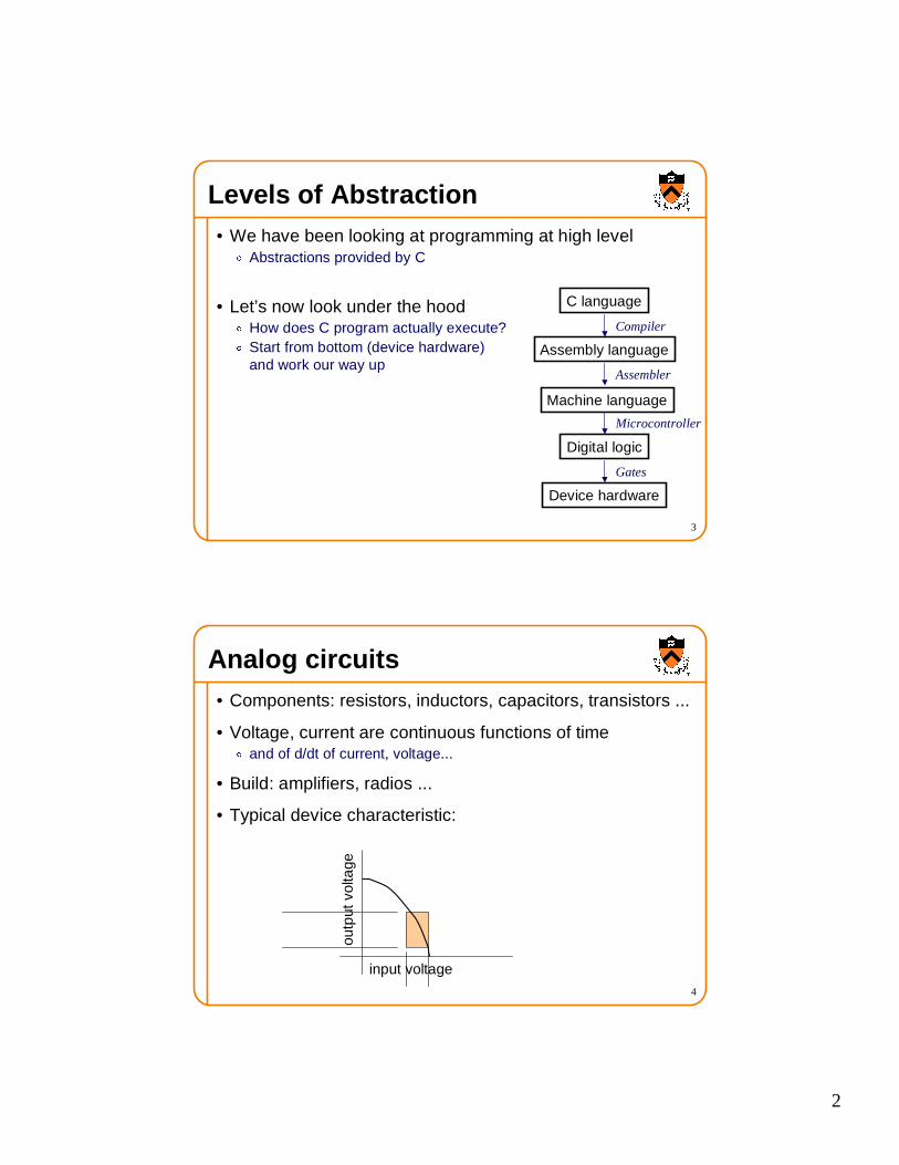
Levels of Abstraction• We have been looking at programming at high level
� Abstractions provided by C
• Let’s now look under the hood� How does C program actually execute?� Start from bottom (device hardware)
and work our way up
C language
Assembly language
Machine language
Digital logic
Device hardware
Compiler
Assembler
Microcontroller
Gates
4
Analog circuits• Components: resistors, inductors, capacitors, transistors ...
• Voltage, current are continuous functions of time� and of d/dt of current, voltage...
• Build: amplifiers, radios ...
• Typical device characteristic:
input voltage
outp
ut v
olta
ge

3
5
Digital circuits• Components: transistors, transistors, transistors ...
� (and the occasional capacitor)
• Pick two voltages of interest: “VCC” and “Ground”
• Build: clocks, adders, computers, computers, computers...� “computers” includes: cell phone, Nintendo, cash register, ...
• Typical device characteristic:
input voltage
outp
ut v
olta
ge device “saturated” ---
we care only about these two points on the graph
Ground
VCC
6
Digital Circuits• Wires, voltage, resistors, ground, etc.
Ground
Vin
Vout
+Vcc
Transistor (electrical switch)
Electricity flows through iffVin exceeds critical value (VC)
Vin Vout
0
Vcc
Vcc
0
This is an NOT gate!
(an inverter)
4
7
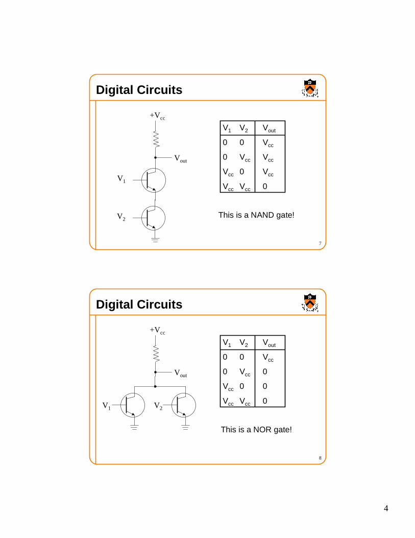
Digital Circuits
V1
Vout
+Vcc
This is a NAND gate!V2
V1 V2 Vout
0 0 Vcc
0 Vcc Vcc
Vcc 0 Vcc
Vcc Vcc 0
8
Digital Circuits
V1
Vout
+Vcc
This is a NOR gate!
V2
V1 V2 Vout
0 0 Vcc
0 Vcc 0
Vcc 0 0
Vcc Vcc 0

5
9
Gates
NAND gate x y x & y also written: xy0 0 10 1 11 0 11 1 0
NOR gate x y x | y also written: x+y0 0 10 1 01 0 01 1 0
NOT gate x ~x also written: x, ¬¬¬¬x
0 11 0
xy
xy
x
10
Gates
AND gate x y x & y also written: xy0 0 00 1 01 0 01 1 1
OR gate x y x | y also written: x+y0 0 00 1 11 0 11 1 1
xy
xy
xy
xy
6
11
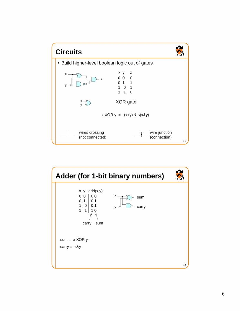
Circuits• Build higher-level boolean logic out of gates
x
y
x y z 0 0 00 1 11 0 11 1 0
z
wires crossing wire junction(not connected) (connection)
XOR gatexy
x XOR y = (x+y) & ¬(x&y)
12
Adder (for 1-bit binary numbers)
x y add(x,y) 0 0 0 00 1 0 11 0 0 11 1 1 0
x
y
carry sum
carry
sum
sum = x XOR y
carry = x&y
7
13
N-bit binary adder
x3 x2 x1 x0 sumi = xi XOR yi XOR carryi-1
+ y3 y2 y1 y0 carryi = (xi & yi ) + ((xi XOR yi )& carryi-1 )
z4 z3 z2 z1 z0
x1 y1
z1
x0 y0
z0
x3 y3
z3
x2 y2
z2
0z4
14
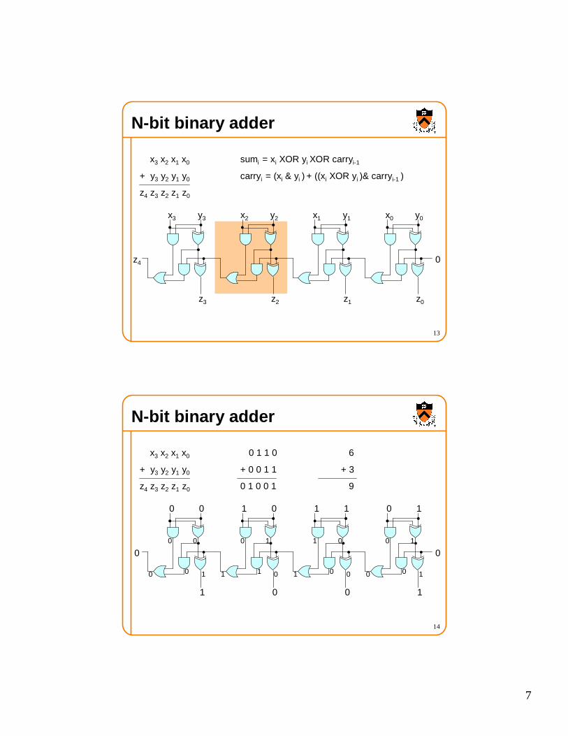
N-bit binary adder
x3 x2 x1 x0 0 1 1 0 6
+ y3 y2 y1 y0 + 0 0 1 1 + 3
z4 z3 z2 z1 z0 0 1 0 0 1 9
1 1
0
0 1
1
0 0
1
1 0
0
0010
0 10
01
0 01
10
1 01
00
0 10

8
15
“ Seat of the pants” design• You just saw it!
• Can be inefficient:
x2 y2
z2
=x2 y2
z2
=
longest path goes through 6 gates; that’s slow
16
Systematic design1. State purpose of circuit in words
2. Make truth tables
3. Identify “true” rows
4. Construct sum-of-products expression
5. Construct circuit

9
17
Systematic design of adder1. State purpose of circuit in words
• Inputs: carry-in, x, y• Outputs: z (if odd number of inputs are 1),
carry-out (if at least two inputs are 1)
2. Make truth tables
Inputs Outputsci n x y z cout
0 0 0 0 00 0 1 1 00 1 0 1 00 1 1 0 11 0 0 1 01 0 1 0 11 1 0 0 11 1 1 1 1
18
3. Identify “true” rows
4. Construct sum-of-products expression (for each output)
z = cin x y + cin x y + cin x y + cin x y
cout = cin x y + cin x y + cin x y + cin x y
Systematic design of adder
ci n x y z
0 0 0 0 0 0 1 1 0 1 0 1 0 1 1 0 1 0 0 1 1 0 1 0 1 1 0 0 1 1 1 1
ci n x y cout
0 0 0 0 0 0 1 0 0 1 0 0 0 1 1 1 1 0 0 0 1 0 1 1 1 1 0 1 1 1 1 1

10
19
z = cin x y + cin x y + cin x y + cin x y
Systematic design of adder
ci n x y z
0 0 0 0 0 0 1 1 0 1 0 1 0 1 1 0 1 0 0 1 1 0 1 0 1 1 0 0 1 1 1 1
5. Construct circuit
cinxy
cinxy
cinxy
cinxy
20
z = cin x y + cin x y + cin x y + cin x y
Sum-of-products circuit
ci n x y z
0 0 0 0 0 0 1 1 0 1 0 1 0 1 1 0 1 0 0 1 1 0 1 0 1 1 0 0 1 1 1 1
cinxy
cinxy
cinxy
cinxy
One AND-gate for each 1-output in table
Each AND-gate has as many inputs as truth table
One OR-gate
Constant-depth: 2 (or 3, counting NOTs)
11
21
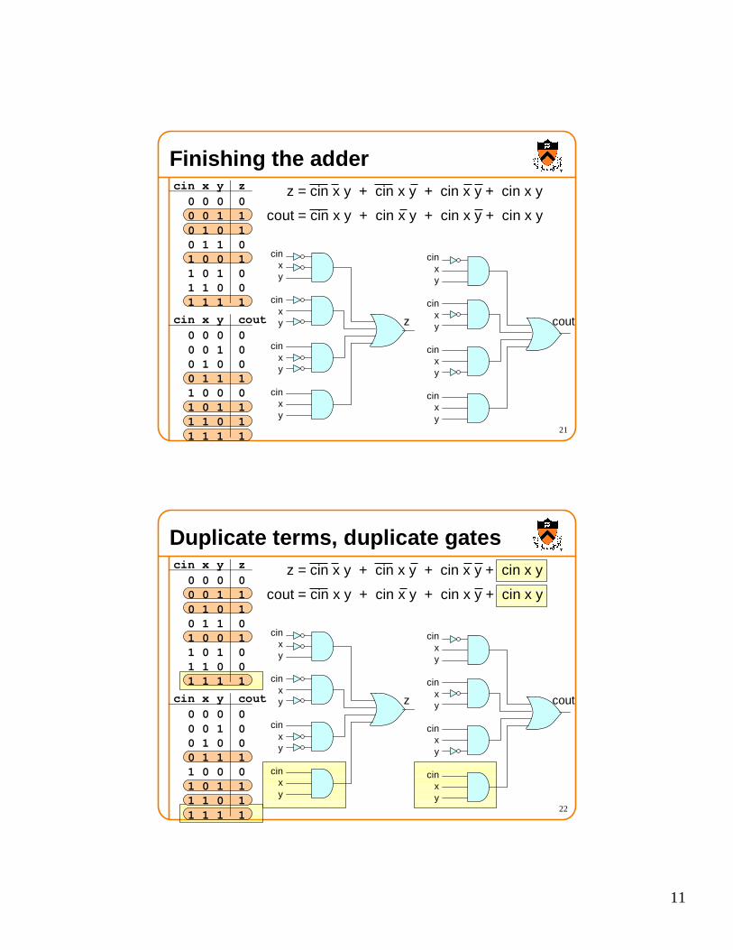
Finishing the adderci n x y z
0 0 0 0 0 0 1 1 0 1 0 1 0 1 1 0 1 0 0 1 1 0 1 0 1 1 0 0 1 1 1 1
cinxy
cinxy
cinxy
cinxy
z = cin x y + cin x y + cin x y + cin x y
cout = cin x y + cin x y + cin x y + cin x y
ci n x y cout
0 0 0 0 0 0 1 0 0 1 0 0 0 1 1 1 1 0 0 0 1 0 1 1 1 1 0 1 1 1 1 1
cinxy
cinxy
cinxy
cinxy
z cout
22
z = cin x y + cin x y + cin x y + cin x y
cout = cin x y + cin x y + cin x y + cin x y
Duplicate terms, duplicate gatesci n x y z
0 0 0 0 0 0 1 1 0 1 0 1 0 1 1 0 1 0 0 1 1 0 1 0 1 1 0 0 1 1 1 1
cinxy
cinxy
cinxy
cinxy
ci n x y cout
0 0 0 0 0 0 1 0 0 1 0 0 0 1 1 1 1 0 0 0 1 0 1 1 1 1 0 1 1 1 1 1
cinxy
cinxy
cinxy
cinxy
z cout
12
23
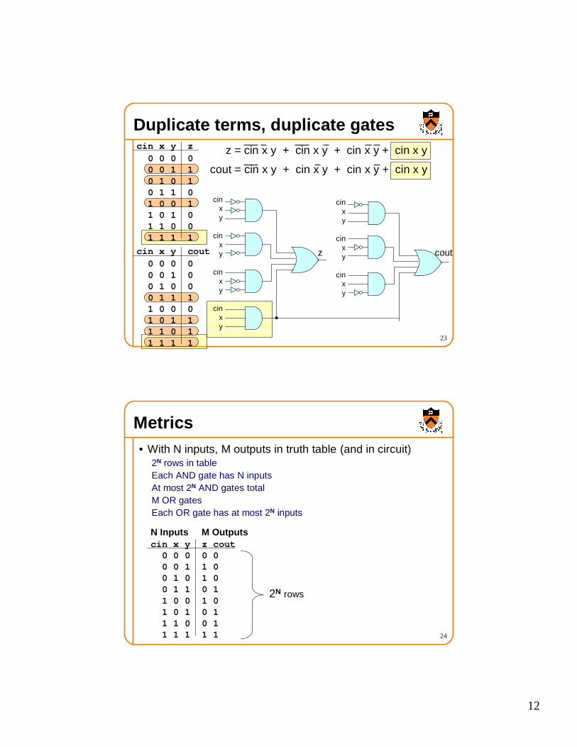
z = cin x y + cin x y + cin x y + cin x y
cout = cin x y + cin x y + cin x y + cin x y
Duplicate terms, duplicate gatesci n x y z
0 0 0 0 0 0 1 1 0 1 0 1 0 1 1 0 1 0 0 1 1 0 1 0 1 1 0 0 1 1 1 1
cinxy
cinxy
cinxy
cinxy
ci n x y cout
0 0 0 0 0 0 1 0 0 1 0 0 0 1 1 1 1 0 0 0 1 0 1 1 1 1 0 1 1 1 1 1
cinxy
cinxy
cinxy
z cout
24
Metrics• With N inputs, M outputs in truth table (and in circuit)
2N rows in tableEach AND gate has N inputsAt most 2N AND gates totalM OR gatesEach OR gate has at most 2N inputs
N Inputs M Outputsci n x y z cout
0 0 0 0 00 0 1 1 00 1 0 1 00 1 1 0 11 0 0 1 01 0 1 0 11 1 0 0 11 1 1 1 1
2N rows

13
25
Advanced stuffcout = cin x y + cin x y + cin x y + cin x y
cout = x y + cin y + cin xci n x y cout
0 0 0 0 0 0 1 0 0 1 0 0 0 1 1 1 1 0 0 0 1 0 1 1 1 1 0 1 1 1 1 1
xy
ciny
cinx
cout
cinxy
cinxy
cinxy
cinxy
cout
Sometimes you can get by with fewer AND gates
To learn how, take ELE 206!
26
Circuit analysis• What does this circuit do?
(pretend you haven’t seen it already)
x2 y2
z2
c1c2
14
27
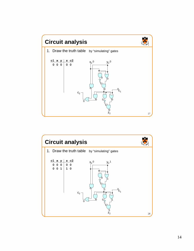
Circuit analysis1. Draw the truth table by “simulating” gates
x2 y2
z2
c1c2
c1 x y z c2
0 0 0 0 0 0 0
00
1
0 0
00
1
0
00
0
28
Circuit analysis1. Draw the truth table by “simulating” gates
x2 y2
z2
c1c2
c1 x y z c2
0 0 0 0 00 0 1 1 0
0 1
10
1
1 0
10
1
1
00
0

15
29
Circuit analysis1. Draw the truth table by “simulating” gates
x2 y2
z2
c1c2
c1 x y z c2
0 0 0 0 00 0 1 1 00 1 0 1 0
1 0
10
1
1 0
10
1
1
00
0
30
Circuit analysis1. Draw the truth table by “simulating” gates
x2 y2
z2
c1c2
c1 x y z c2
0 0 0 0 00 0 1 1 00 1 0 1 00 1 1 0 1
1 1
11
0
0 0
00
1
0
10
1

16
31
Circuit analysis1. Draw the truth table
x2 y2
z2
c1c2
c1 x y z c2
0 0 0 0 0 0 0 1 1 0 0 1 0 1 0 0 1 1 0 1 1 0 0 1 0 1 0 1 0 1 1 1 0 0 1 1 1 1 1 1
32
Circuit analysis2. Say in words what the truth table does
c1 x y z c2
0 0 0 0 0 0 0 1 1 0 0 1 0 1 0 0 1 1 0 1 1 0 0 1 0 1 0 1 0 1 1 1 0 0 1 1 1 1 1 1
z is 1 if an odd number of inputs are 1
c2 is 1 if at least two inputs are 1

17
33
Circuit analysis3. Apply a flash of insight
c1 x y z c2
0 0 0 0 0 0 0 1 1 0 0 1 0 1 0 0 1 1 0 1 1 0 0 1 0 1 0 1 0 1 1 1 0 0 1 1 1 1 1 1
z is 1 if an odd number of inputs are 1
c2 is 1 if at least two inputs are 1
Aha! It’s one bit-slice of an adder!
34
Summary• Digital Circuits
� Boolean logic� Combinatorial circuits
• Next lectures� Sequential circuits� Building a computer
D
Clock
Q
X