digital circuit engineering - carleton...
TRANSCRIPT

© John Knight
Seq3ProdFSM_C.fmI p. 1 Revised; April 8, 2009
Digital Circuit Engineering
Carleton University 2008
DIGITAL
VLSI
D GN
Product State Graphs
ESI
Slide i
Carleton University © John Knight Seq3ProdFSM_C.fm p. 2, Revised; April 8, 2009
Comment on Slide i
Special State GraphsChecking for Dual Sequences
1101 or 1011 Mealy Detection Product Graph
010001 or 0101 Moore Detector Product GraphOne-Pulse-Per-Push Circuit Mealy Moore
Coupled State Machines
© John Knight
Seq3ProdFSM_C.fm p. 3 Revised; April 8, 2009
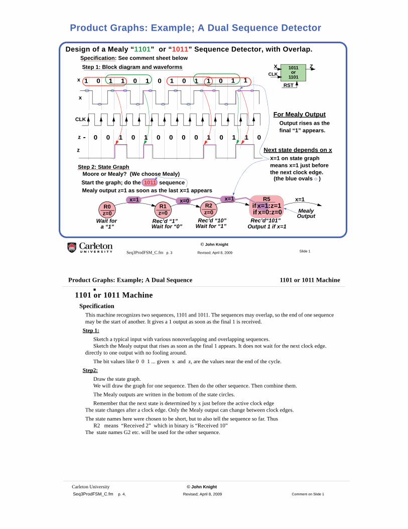
Design of a Mealy “1101” or “1011” Sequence Detector, with Overlap.
Step 2: State Graph
Start the graph; do the 1011 sequenceMoore or Mealy? (We choose Mealy)
R0z=0 Mealy
Wait fora “1”
R1z=0
Wait for “0”
OutputRec’d “1”
Output 1 if x=1 Rec’d “10”
x=1 x=0 x=1Mealy output z=1 as soon as the last x=1 appears
1 0 1 1 0 1 0 1 10 1 10 1x
x
CLKFor Mealy Output
Output rises as the
- 0 0 1 0 1 0 0 00 1 10 1 0z
Step 1: Block diagram and waveforms
R2z=0
x=1
Rec’d“101”Wait for “1”
1011XCLK
RST
Zor
1101
z
final “1” appears.
Next state depends on xx=1 on state graph
the next clock edge.means x=1 just before
(the blue ovals )
Specification: See comment sheet below
R5if x=1:z=1if x=0:z=0
Slide 1
Product Graphs: Example; A Dual Sequence Detector
Carleton University © John Knight Seq3ProdFSM_C.fm p. 4, Revised; April 8, 2009
Product Graphs: Example; A Dual Sequence 1101 or 1011 Machine
1101 or 1011 MachineSpecification
This machine recognizes two sequences, 1101 and 1011. The sequences may overlap, so the end of one sequence may be the start of another. It gives a 1 output as soon as the final 1 is received.
Step 1:Sketch a typical input with various nonoverlapping and overlapping sequences.
Sketch the Mealy output that rises as soon as the final 1 appears. It does not wait for the next clock edge. directly to one output with no fooling around.
The bit values like 0 0 1 ... given x and z, are the values near the end of the cycle.Step2:
Draw the state graph. We will draw the graph for one sequence. Then do the other sequence. Then combine them.The Mealy outputs are written in the bottom of the state circles.Remember that the next state is determined by x just before the active clock edge
The state changes after a clock edge. Only the Mealy output can change between clock edges.The state names here were chosen to be short, but to also tell the sequence so far. Thus R2 means “Received 2” which in binary is “Received 10”The state names G2 etc. will be used for the other sequence.
Comment on Slide 1
© John Knight
Seq3ProdFSM_C.fm p. 5 Revised; April 8, 2009
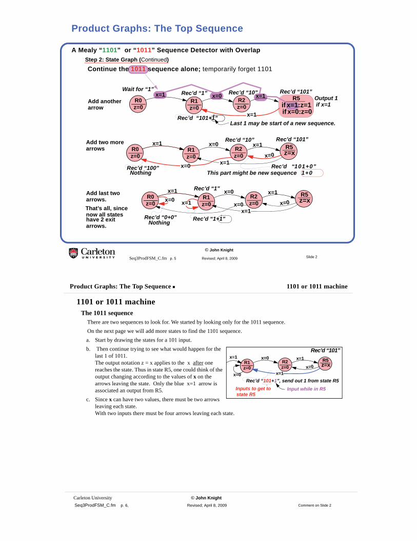
A Mealy “1101” or “1011” Sequence Detector with Overlap
Continue the 1011 sequence alone; temporarily forget 1101Step 2: State Graph (Continued)
R0z=0
Wait for “1”Output 1
Rec’d “10”R5
if x=1:z=1R2z=0
x=1Rec’d “101”
R1z=0
Rec’d “1”x=1
x=1
if x=1
R0z=0
R5z=xR2
z=0
x=1R1z=0
x=1 x=0
x=0
Rec’d “101+1”Last 1 may be start of a new sequence.
Rec’d “101+0” x=1
x=0
x=0Rec’d “100”Nothing
Add anotherarrow
Add two morearrows
R0z=0
R5z=xR2
z=0
x=1R1z=0
x=1 x=0
x=0x=0
x=1x=0x=1
NothingRec’d “0+0” Rec’d “1+1”
Add last twoarrows.That’s all, since
have 2 exitarrows.
now all states
if x=0:z=0
Rec’d “101”Rec’d “10”
Rec’d “1”
This part might be new sequence 1+0
Slide 2
Product Graphs: The Top Sequence
Carleton University © John Knight Seq3ProdFSM_C.fm p. 6, Revised; April 8, 2009
Product Graphs: The Top Sequence 1101 or 1011 machine
1101 or 1011 machineThe 1011 sequence
There are two sequences to look for. We started by looking only for the 1011 sequence.On the next page we will add more states to find the 1101 sequence.a. Start by drawing the states for a 101 input.b. Then continue trying to see what would happen for the
last 1 of 1011.The output notation z = x applies to the x after one reaches the state. Thus in state R5, one could think of the output changing according to the values of x on the arrows leaving the state. Only the blue x=1 arrow is associated an output from R5.
c. Since x can have two values, there must be two arrows leaving each state.With two inputs there must be four arrows leaving each state.
R5z=xR2
z=0
x=1R1z=0
x=0
x=0x=1x=0
x=1
Rec’d “101+1”, send out 1 from state R5
Rec’d “101”
Inputs to get to Input while in R5state R5
Comment on Slide 2
© John Knight
Seq3ProdFSM_C.fm p. 7 Revised; April 8, 2009
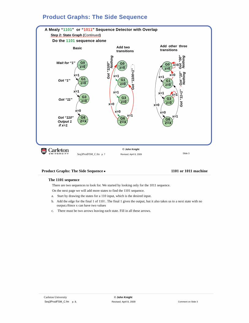
A Mealy “1101” or “1011” Sequence Detector with Overlap
Do the 1101 sequence aloneStep 2: State Graph (Continued)
G1z=0
Got “1”
G3z=0Got “11”
Output 1G6z=x
Got “110”
G0z=0
Wait for “1”
x=1
x=1
x=0
G1z=0
G3z=0
G6z=x
G0z=0
x=0
x=0x=1
x=1
x=0
x=0
x=1
x=1
G1z=0
G3z=0
G6z=x
G0z=0
x=1
x=1
x=0
x=0
x=1
if x=1
Basic
Got
“11
00+1
”
Got
“11
00”
Not
hing
Got
“00
”N
othi
ngG
ot “
10”
Not
hing
Got
“11
+1”
Add two Add other threetransitions transitions
Slide 3
Product Graphs: The Side Sequence
Carleton University © John Knight Seq3ProdFSM_C.fm p. 8, Revised; April 8, 2009
Product Graphs: The Side Sequence 1101 or 1011 machine
The 1101 sequence There are two sequences to look for. We started by looking only for the 1011 sequence.On the next page we will add more states to find the 1101 sequence.a. Start by drawing the states for a 110 input, which is the desired input.b. Add the edge for the final 1 of 1101. The final 1 gives the output, but it also takes us to a next state with no
ourput.rSince x can have two valuesc. There must be two arrows leaving each state. Fill in all these arrows.
Comment on Slide 3

© John Knight
Seq3ProdFSM_C.fm p. 9 Revised; April 8, 2009
The Product State Graph for the Mealy “1101” or “1011” Sequence Detector
The two state graphs define the machineStep 2: State Graph (Combining the two graphs))
G1z=0
G3z=0
G6z=x
G0z=0
10
0
1
10
0
1
R0z=0
R5z=x
R2z=0
R1z=0 0
0101
11
0
x
z
You can make a a working machine as shown.It will be larger than needed.
The two graphs can be combined into a product graph (next slide)• This has a large number of states.
• This product graph canbe reduced to less than the
• The reduced product graph usually gives a smaller circuit.
two individual graphs.
START OF A “PRODUCT” GRAPH
Make two separate machines,and OR the outputs.
1011 machine
1101
mac
hine
Slide 4
Product State Graphs: Combining Outputs
Carleton University © John Knight Seq3ProdFSM_C.fm p. 10, Revised; April 8, 2009
Product State Graphs: Combining Outputs 1101 or 1011 machine
The Machine Made From Two Submachines.
1DC1R
1DC1R
Z
F
FG
GG
X F
G
G
F
1DC1R
1DC1R
PQ
P
Q
X
X
One way to build the machine.It can be made smaller!
1011 machine
1101 machine
Comment on Slide 4

© John Knight
Seq3ProdFSM_C.fm p. 11 Revised; April 8, 2009
The product states
R0z=0
Wait for “1”
G1z=0
Got 1
Output 1
Rec 10R5z=xR2
z=0
x=1Rec 101
G3z=0
Got 11
Output 1 if x=1
G6z=x
Got 110
1011 is wanted
R1z=0
Rec 1x=1 x=0
x=0x=1
x=1x=0x=0
if x=1
G0z=0
Wait for “1”
x=0
x=0x=1
x=1
x=0
x=0
x=1
x=1
G0R0z=0
G1R0z=0
G3R0z=0
G6R0z=x
G0R1z=0
G1R1z=0
G3R1z=0
G6R1z=x
G0R2z=0
G1R2z=0
G3R2z=0
G6R2z=x
G0R5z=x
G1R5z=x
G3R5z=x
G6R5z=x1101 is
wanted
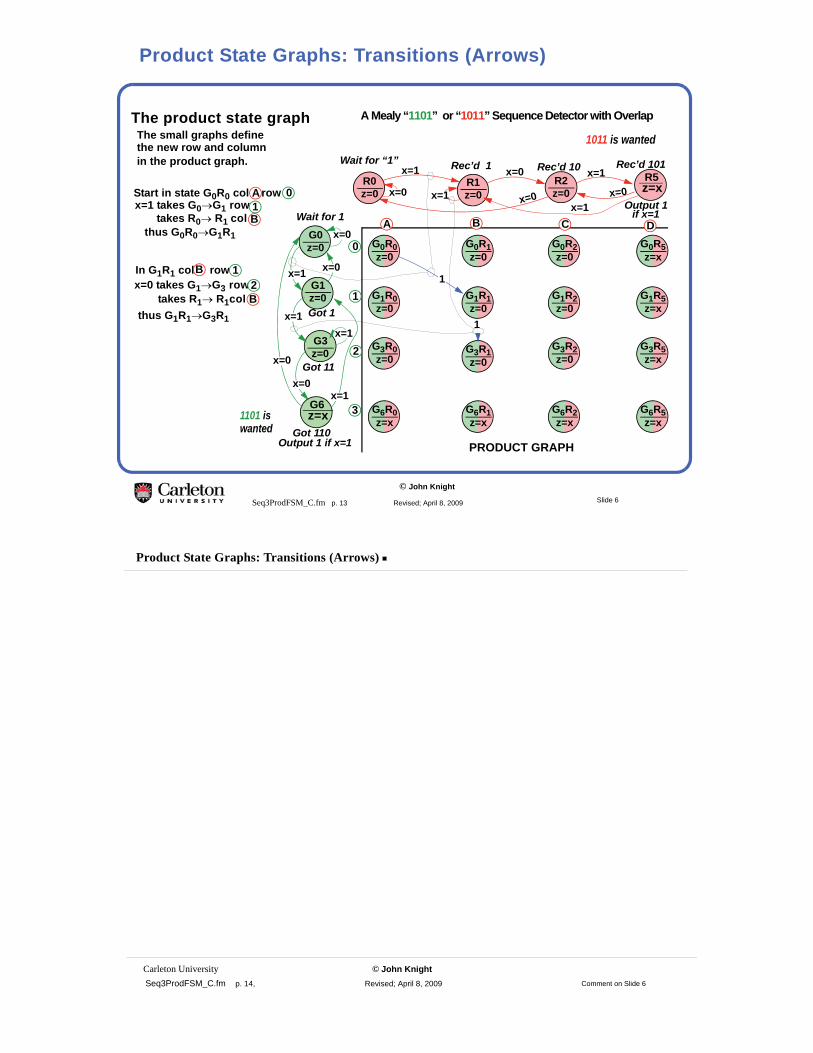
A new combined state graphThe product graphMerge the G and R statesto get a new GR state for each row and column.
Most of the new stateswill be unused.
The final product graph should be smaller than the side and top graphs together
A Mealy “1101” or “1011” Sequence Detector with Overlap
Slide 5
Product State Graphs: Combining States
Carleton University © John Knight Seq3ProdFSM_C.fm p. 12, Revised; April 8, 2009
Product State Graphs: Combining States 1101 or 1011 machine
One Way to Combine the GraphsThe combined graph will be done on the slides using a product graph. NamesThe original names like G5 means we got 101 (binary 5). Here we give the state two names, thus G3R2 means we got 3 (binary 11) along the G (green) sequence, and 2 (binary 10) along the R (red) sequence, both simultaneously.
Comment on Slide 5
© John Knight
Seq3ProdFSM_C.fm p. 13 Revised; April 8, 2009
The product state graph
R0z=0
Wait for “1”
G1z=0Got 1
Output 1
Rec’d 10R5z=xR2
z=0
x=1Rec’d 101
G3z=0
Got 11
Output 1 if x=1
G6z=x
Got 110
1011 is wanted
R1z=0
Rec’d 1x=1 x=0
x=0x=1
x=1x=0x=0
if x=1
G0z=0
Wait for 1x=0
x=0x=1
x=1
x=0
x=0
x=1
x=1
G0R0z=0
G1R0z=0
G3R0z=0
G6R0z=x
G0R1z=0
G1R1z=0
G3R1z=0
G6R1z=x
G0R2z=0
G1R2z=0
G3R2z=0
G6R2z=x
G0R5z=x
G1R5z=x
G3R5z=x
G6R5z=x
1
1
1101 is wanted
In G1R1 col row
x=1 takes G0→G1 row BBA DC
0
1
2
3
0A
takes R0→ R1 colthus G0R0→G1R1
Start in state G0R0 col row
1BBx=0 takes G1→G3 row
takes R1→ R1colthus G1R1→G3R1
the new row and columnin the product graph.
The small graphs define
1BB
BB2
A Mealy “1101” or “1011” Sequence Detector with Overlap
PRODUCT GRAPH
Slide 6
Product State Graphs: Transitions (Arrows)
Carleton University © John Knight Seq3ProdFSM_C.fm p. 14, Revised; April 8, 2009
Product State Graphs: Transitions (Arrows)
Comment on Slide 6
© John Knight
Seq3ProdFSM_C.fm p. 15 Revised; April 8, 2009
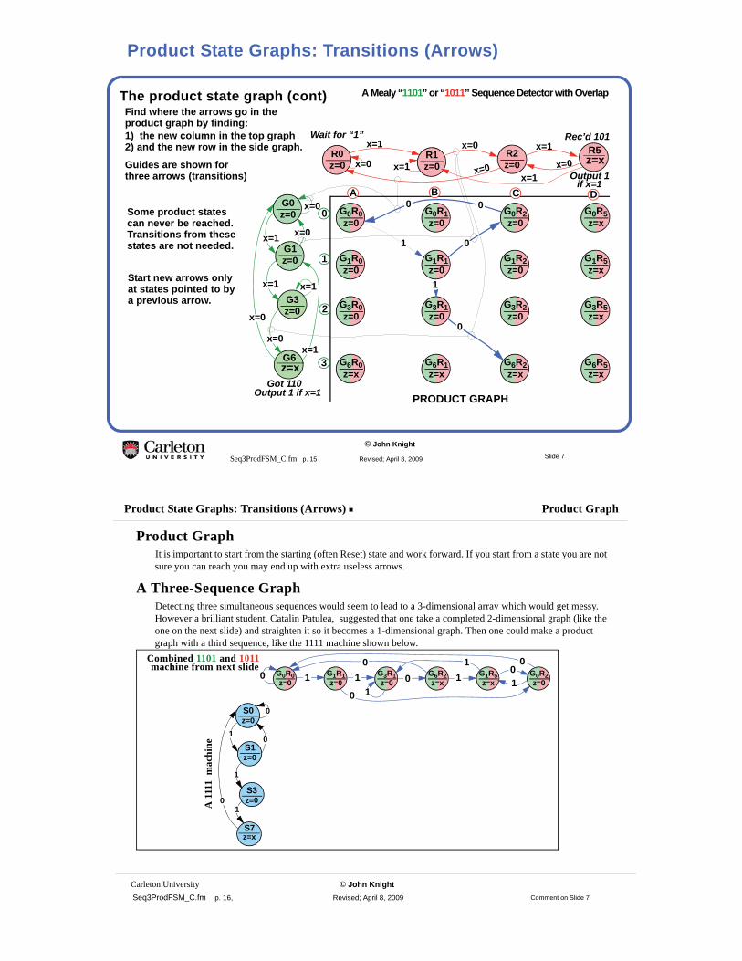
The product state graph (cont)
R0z=0
Wait for “1”
G1z=0
Output 1
R5z=xR2
z=0
x=1
G3z=0
Output 1 if x=1
G6z=x
Got 110
R1z=0
x=1 x=0
x=0x=1
x=1x=0x=0
if x=1
G0z=0
x=0
x=0x=1
x=1
x=0
x=0
x=1
x=1
G0R0z=0
G1R0z=0
G3R0z=0
G6R0z=x
G0R1z=0
G1R1z=0
G3R1z=0
G6R1z=x
G0R2z=0
G1R2z=0
G3R2z=0
G6R2z=x
G0R5z=x
G1R5z=x
G3R5z=x
G6R5z=x
1 0
1
0
0
BBA DC
0
1
2
3
product graph by finding:1) the new column in the top graph
Find where the arrows go in the
0
2) and the new row in the side graph.
Guides are shown for three arrows (transitions)
Some product statescan never be reached.Transitions from thesestates are not needed.
Start new arrows onlyat states pointed to bya previous arrow.
A Mealy “1101” or “1011” Sequence Detector with Overlap
Rec’d 101
PRODUCT GRAPH
Slide 7
Product State Graphs: Transitions (Arrows)
Carleton University © John Knight Seq3ProdFSM_C.fm p. 16, Revised; April 8, 2009
Product State Graphs: Transitions (Arrows) Product Graph
Product GraphIt is important to start from the starting (often Reset) state and work forward. If you start from a state you are not sure you can reach you may end up with extra useless arrows.
A Three-Sequence GraphDetecting three simultaneous sequences would seem to lead to a 3-dimensional array which would get messy. However a brilliant student, Catalin Patulea, suggested that one take a completed 2-dimensional graph (like the one on the next slide) and straighten it so it becomes a 1-dimensional graph. Then one could make a product graph with a third sequence, like the 1111 machine shown below.
0 G0R0z=0
G1R1z=0
G3R1z=0
G6R2z=x
G1R5z=x
G0R2z=01 1 0 1
10
0 1 001
S1z=0
S3z=0
S7z=x
S0z=0
10
0
01
1
A 1
111
mac
hine
Combined 1101 and 1011machine from next slide
Comment on Slide 7
© John Knight
Seq3ProdFSM_C.fm p. 17 Revised; April 8, 2009
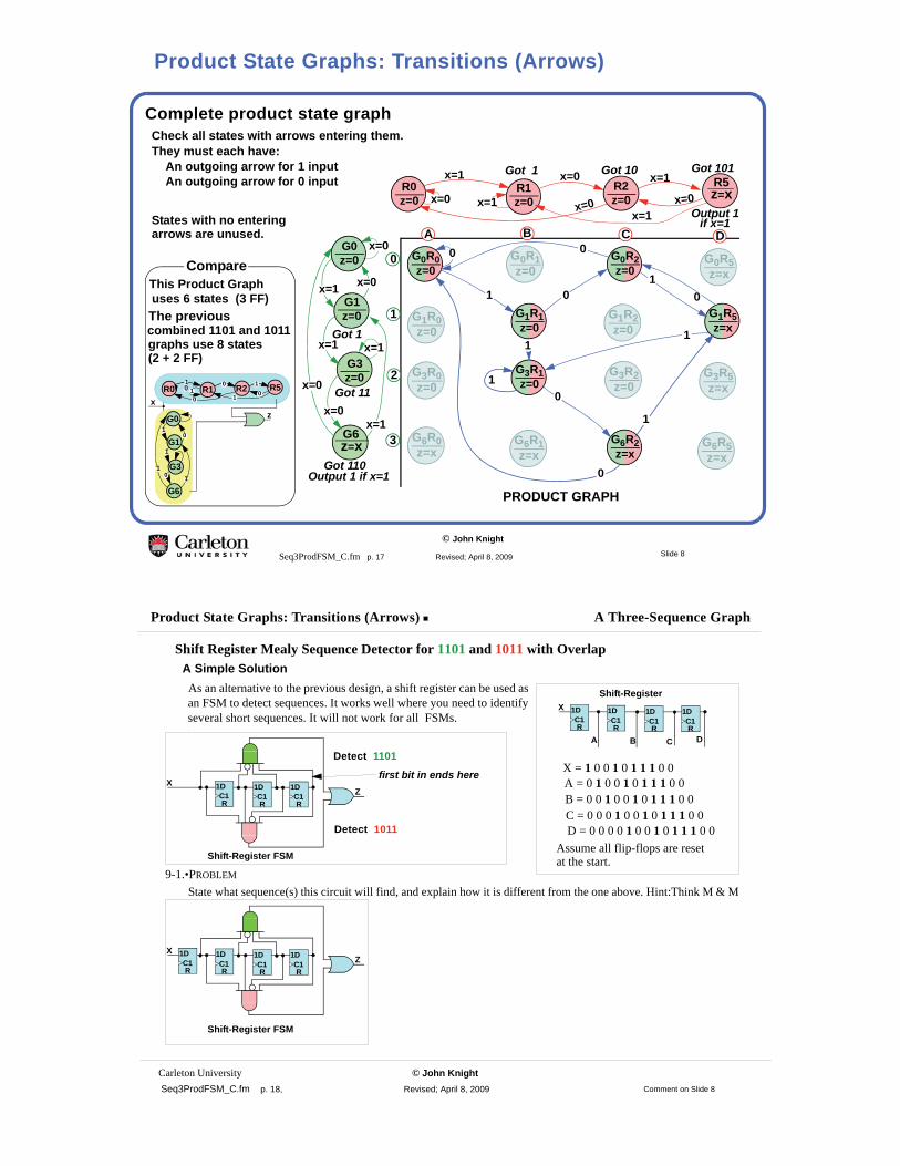
Complete product state graph
R0z=0
G1z=0
Got 1
Output 1
Got 10R5z=xR2
z=0
x=1Got 101
G3z=0
Got 11
Output 1 if x=1
G6z=x
Got 110
R1z=0
Got 1x=1 x=0
x=0x=1
x=1x=0x=0
if x=1
G0z=0
x=0
x=0x=1
x=1
x=0
x=0
x=1
x=1
G0R0z=0
G1R1z=0
G3R1z=0
G0R2z=0
G6R2z=x
G1R5z=x
1 0
1
0
1
10
0
0
BBA DC
0
1
2
3
They must each have:
States with no entering
Check all states with arrows entering them.
0
1
1
An outgoing arrow for 1 inputAn outgoing arrow for 0 input
arrows are unused.
G1R2z=0
G1R0z=0
G6R0z=x
G3R0z=0
G6R1z=x
G3R2z=0
G0R5z=x
G6R5z=x
G3R5z=x
G0R1z=0
This Product Graph
G1
G3
G6
G0
R0 R5R2R1 00 101
110x
z1
0
0 11
1
uses 6 states (3 FF)
combined 1101 and 1011graphs use 8 states
Compare
PRODUCT GRAPH
The previous
(2 + 2 FF)
Slide 8
Product State Graphs: Transitions (Arrows)
Carleton University © John Knight Seq3ProdFSM_C.fm p. 18, Revised; April 8, 2009
Product State Graphs: Transitions (Arrows) A Three-Sequence Graph
Comment on Slide 8
Shift Register Mealy Sequence Detector for 1101 and 1011 with OverlapA Simple SolutionAs an alternative to the previous design, a shift register can be used as an FSM to detect sequences. It works well where you need to identify several short sequences. It will not work for all FSMs..
9-1.•PROBLEM
State what sequence(s) this circuit will find, and explain how it is different from the one above. Hint:Think M & M
1DC1R
1DC1R
1DC1R
1DC1R
XShift-Register
A B C D
X = 1 0 0 1 0 1 1 1 0 0 A = 0 1 0 0 1 0 1 1 1 0 0 B = 0 0 1 0 0 1 0 1 1 1 0 0 C = 0 0 0 1 0 0 1 0 1 1 1 0 0 D = 0 0 0 0 1 0 0 1 0 1 1 1 0 0
Assume all flip-flops are resetat the start.
1DC1R
1DC1R
1DC1R
ZX
Shift-Register FSM
Detect 1101
Detect 1011
first bit in ends here
1DC1R
1DC1R
1DC1R
1DC1R
ZX
Shift-Register FSM

© John Knight
Seq3ProdFSM_C.fm p. 19 Revised; April 8, 2009
Synchronous State Graph 010001 or 0101 Detector
Moore Output: Output rises in clock period
Step 1: Block diagram and waveforms010001X
CLK
RST
Zor
0101
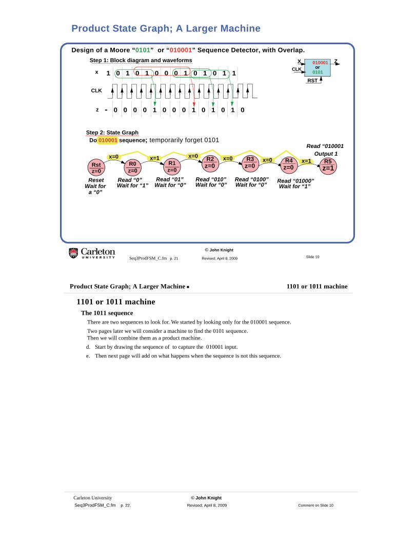
Design a state graph for a machine with:One input X, one output Z. Z=1 after receiving the complete sequence 010001 or 0101 Overlapped sequences are detected.
Solution:
Z=0 except for the single clock period after the sequence is received.
after sequence is received
1 0 1 0 1 0 0 0 01 1 10 1x
CLK
- 0 0 0 0 1 0 0 10 0 01 1 0z
Slide 9
Another Product State Graph Example
Carleton University © John Knight Seq3ProdFSM_C.fm p. 20, Revised; April 8, 2009
Another Product State Graph Example 010001 or 0101 Machine
Comment on Slide 9
010001 or 0101 Machine
This machine recognizes two sequences. The sequences may overlap, so the end of one sequence may be the start of another.
Step 1:By now, you should be able to write the input sequence as 1s and 0s, knowing that these are the final values
of the input as they appear just before the next active clock edge. These sequences should illustrate various overlapping sequences. The output here is a Moore output, so it rises after the clock cycle in which the final 1 appears.
Step2:Draw the state graph. We will draw the graph for one sequence. Then do the other sequence. Then combine them.The Moore outputs are written in the bottom of the state circles.Remember that the next state is determined by x just before the active clock edge
The state changes after a clock edge. Also Moore output only change just after the active clock edge.
9-2.•PROBLEM
Design the state graph for a Mealy machine with overlap, which detects the seqence
© John Knight
Seq3ProdFSM_C.fm p. 21 Revised; April 8, 2009
Design of a Moore “0101” or “010001” Sequence Detector, with Overlap.
Step 2: State GraphDo 010001 sequence; temporarily forget 0101
Rstz=0
Wait fora “0”
R0z=0
Wait for “1”Read “0”
Output 1
Read “01”
x=0 x=1 R2z=0
Step 1: Block diagram and waveforms
R1z=0
x=0
Read “010”Wait for “0”
010001XCLK
RST
Zor
01011 0 1 0 1 0 0 0 01 1 10 1x
CLK
- 0 0 0 0 1 0 0 10 0 01 1 0z
ResetWait for “0”
x=0 R3z=0
Read “0100”Wait for “0”
x=0 R4z=0
Read “01000”Wait for “1”
x=1 R5z=1
Read “010001
Slide 10
Product State Graph; A Larger Machine
Carleton University © John Knight Seq3ProdFSM_C.fm p. 22, Revised; April 8, 2009
Product State Graph; A Larger Machine 1101 or 1011 machine
1101 or 1011 machineThe 1011 sequence
There are two sequences to look for. We started by looking only for the 010001 sequence.Two pages later we will consider a machine to find the 0101 sequence.Then we will combine them as a product machine.d. Start by drawing the sequence of to capture the 010001 input.e. Then next page will add on what happens when the sequence is not this sequence.
Comment on Slide 10
© John Knight
Seq3ProdFSM_C.fm p. 23 Revised; April 8, 2009
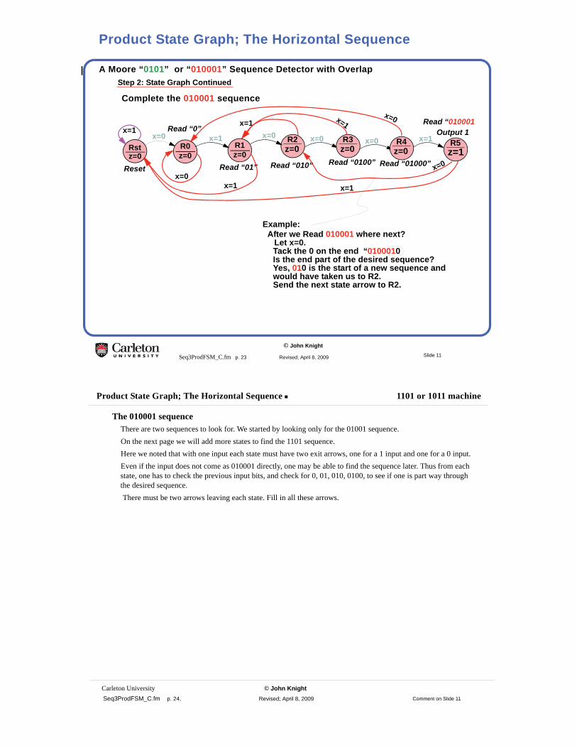
A Moore “0101” or “010001” Sequence Detector with Overlap
Complete the 010001 sequence
Step 2: State Graph Continued
Rstz=0
R0z=0
Read “0” Output 1
Read “01”
x=0 x=1 R2z=0R1
z=0
x=0
Read “010”Reset
x=0 R3z=0
Read “0100”
x=0 R4z=0
Read “01000”
x=1 R5z=1
x=0x=1
x=1 x=1x=0
x=1
Read “010001”
x=0
x=1
Example:After we Read 010001 where next?
Let x=0.Tack the 0 on the end “0100010Is the end part of the desired sequence?Yes, 010 is the start of a new sequence andwould have taken us to R2.Send the next state arrow to R2.
Slide 11
Product State Graph; The Horizontal Sequence
Carleton University © John Knight Seq3ProdFSM_C.fm p. 24, Revised; April 8, 2009
Product State Graph; The Horizontal Sequence 1101 or 1011 machine
The 010001 sequence There are two sequences to look for. We started by looking only for the 01001 sequence.On the next page we will add more states to find the 1101 sequence.Here we noted that with one input each state must have two exit arrows, one for a 1 input and one for a 0 input.Even if the input does not come as 010001 directly, one may be able to find the sequence later. Thus from each state, one has to check the previous input bits, and check for 0, 01, 010, 0100, to see if one is part way through the desired sequence. There must be two arrows leaving each state. Fill in all these arrows.
Comment on Slide 11

© John Knight
Seq3ProdFSM_C.fm p. 25 Revised; April 8, 2009
A Moore “0101” or “010001” Sequence Detector with Overlap
Do the 0101 sequence alone; temporarily forget 010001Step 2: State Graph (Continued)
Rstz=0
Wait for “0” Output 1Got “01”G2z=0
G1z=0
x=0Got “010”
G0z=0
Got “0”x=0 x=1 G3z=1
x=1Got “0101”
Rstz=0
Wait for “0” Output 1Got “01”G2z=0
G1z=0
x=0Got “010”
G0z=0
Got “0”
x=0 x=1 G3z=1
x=1Got “0101”
x=1x=0 x=1
x=0
x=0
x=1
Draw in the arrows for the sequence we want
Draw in the side arrows to give to arrows out of each state
Slide 12
Product State Graph; The Vertical Sequence
Carleton University © John Knight Seq3ProdFSM_C.fm p. 26, Revised; April 8, 2009
Product State Graph; The Vertical Sequence 1101 or 1011 machine
The 0101 SubmachineWe now have two machines, one two detect each sequence. The next step is to consider both machines operating at once.
Comment on Slide 12
© John Knight
Seq3ProdFSM_C.fm p. 27 Revised; April 8, 2009
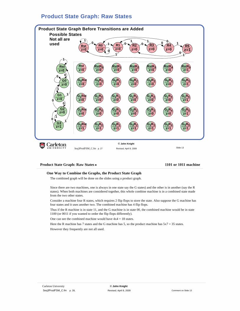
Product State Graph Before Transitions are Added
0
Possible States
Rstz=0
G0Rstz=0
G2Rstz=0
G3Rstz=1
Rstz=0
R0z=0
R2z=0
R1z=0
R3z=0
0R4
z=01
R5z=1
10
1 10
0 01 1 0
Rstz=0
G2z=0
G1z=0
G0z=0
G3z=1
0
0
1
11
1
0
1
0
0
G1Rstz=0
RstR0z=0
G0R0z=0
G2R0z=0
G3R0z=1
G1R0z=0
G0R1z=0
G2R1z=0
G3R1z=1
G1R1z=0
G0R2z=0
G2R2z=0
G3R2z=1
G1R2z=0
G0R3z=0
G2R3z=0
G3R3z=1
G1R3z=0
G0R4z=0
G2R4z=0
G3R4z=1
G1R4z=0
G0R5z=1
G2R5z=1
G3R5z=1
G1R5z=1
RstR1z=0
RstR2z=0
RstR3z=0
RstR4z=0
RstR5z=1
Not all areused
1
Slide 13
Product State Graph: Raw States
Carleton University © John Knight Seq3ProdFSM_C.fm p. 28, Revised; April 8, 2009
Product State Graph: Raw States 1101 or 1011 machine
One Way to Combine the Graphs, the Product State GraphThe combined graph will be done on the slides using a product graph.
Since there are two machines, one is always in one state say the G states) and the other is in another (say the R states). When both machines are considered together, this whole combine machine is in a combined state made from the two other states. Consider a machine four R states, which requires 2 flip flops to store the state. Also suppose the G machine has four states and it uses another two. The combined machine has 4 flip flops. Thus if the R machine is in state 11, and the G machine is in state 00, the combined machine would be in state 1100 (or 0011 if you wanted to order the flip flops differently).One can see the combined machine would have 4x4 = 18 states.Here the R machine has 7 states and the G machine has 5, so the product machine has 5x7 = 35 states.However they frequently are not all used.
Comment on Slide 13

© John Knight
Seq3ProdFSM_C.fm p. 29 Revised; April 8, 2009
Product State Graph; Main Transitions are Added
0
0
0
Add the transitions for the desired sequences 010001 and 0101
Rstz=0
G0Rstz=0
G2Rstz=0
G3Rstz=1
Rstz=0
R0z=0
R2z=0
R1z=0
R3z=0
0R4
z=01
R5z=1
1
1 10
0 01 1 0
Rstz=0
G2z=0
G1z=0
G0z=0
G3z=1
1
11
1
0
1
0
0
G1Rstz=0
RstR0z=0
G0R0z=0
G2R0z=0
G3R0z=1
G1R0z=0
G0R1z=0
G2R1z=0
G3R1z=1
G1R1z=0
G0R2z=0
G2R2z=0
G3R2z=1
G1R2z=0
G0R3z=0
G2R3z=0
G3R3z=1
G1R3z=0
G0R4z=0
G2R4z=0
G3R4z=1
G1R4z=0
G0R5z=1
G2R5z=1
G3R5z=1
G1R5z=1
RstR1z=0
RstR2z=0
RstR3z=0
RstR4z=0
RstR5z=1
1
0
0
1
0
1
0
0
1
Slide 14
Product State Graph; The Main Sequences
Carleton University © John Knight Seq3ProdFSM_C.fm p. 30, Revised; April 8, 2009
Product State Graph; The Main Sequences 1101 or 1011 machine
The Product State-TableHaving named the stages, and plotted them on an x-y grid, the next step is to add transitions.Start by adding the transitions that would happen if the machine received exactly the right sequence.First 0101 and then 010001.
Starting at RstA 0 is received:Look at the green machine, and one sees a 0 takes one to G0. i.e. row 2.Look at the red machine, and one sees a 0 takes one to R0, i.e. column 2.Hence the next product state is G0R0 in row 2 and column 2.Now let a 1 be received.For the green machine, starting in state G0, a 1 takes one to state G1For the red machine, starting in state R0, a 1 takes one to state R1.Hence for the product machine, starting in state G0R0, a 1 takes one to state G1R1.Continue adding the transitions (that’s jargon for the arrows) for the 0101 sequence.Then repeat for the 010001 sequence starting from Rst.
The Product State-TableOne could, instead of adding the transitions to the graph, make a state table directly. In this case it turns out to be more work. In some cases, particularly where the graph is large and messy, the state table is easier.
Comment on Slide 14

© John Knight
Seq3ProdFSM_C.fm p. 31 Revised; April 8, 2009
Product State Graph; Add the transitions leaving states reached before.
0
Each state has two exits
Rstz=0
G0Rstz=0
G2Rstz=0
G3Rstz=1
Rstz=0
R0z=0
R2z=0
R1z=0
R3z=0
0R4
z=01
R5z=1
1
1 10
0 01 1 0
Rstz=0
G2z=0
G1z=0
G0z=0
G3z=1
0
0
1
11
1
0
1
0
0
G1Rstz=0
RstR0z=0
G0R0z=0
G2R0z=0
G3R0z=1
G1R0z=0
G0R1z=0
G2R1z=0
G3R1z=1
G1R1z=0
G0R2z=0
G2R2z=0
G3R2z=1
G1R2z=0
G0R3z=0
G2R3z=0
G3R3z=1
G1R3z=0
G0R4z=0
G2R4z=0
G3R4z=1
G1R4z=0
G0R5z=1
G2R5z=1
G3R5z=1
G1R5z=1
RstR1z=0
RstR2z=0
RstR3z=0
RstR4z=0
RstR5z=1
1
0
0
1
1
0
0
0
1
1
1
1
0
0
0
1
Slide 15
Product State Graph; Other Sequences
Carleton University © John Knight Seq3ProdFSM_C.fm p. 32, Revised; April 8, 2009
Product State Graph; Other Sequences Transitions in the Product State Table
Transitions in the Product State TableFilling in Transitions not done beforeSeveral of the states that were reached on the last slide, have only one, or perhaps zero, exit arrows.Each state needs two exit arrows, so fill those in now.Note that one state G1R2 now has an arrow going into it, whereas previously it did not.We will add the exit arrow from G1R2 on the next page.
Comment on Slide 15
© John Knight
Seq3ProdFSM_C.fm p. 33 Revised; April 8, 2009
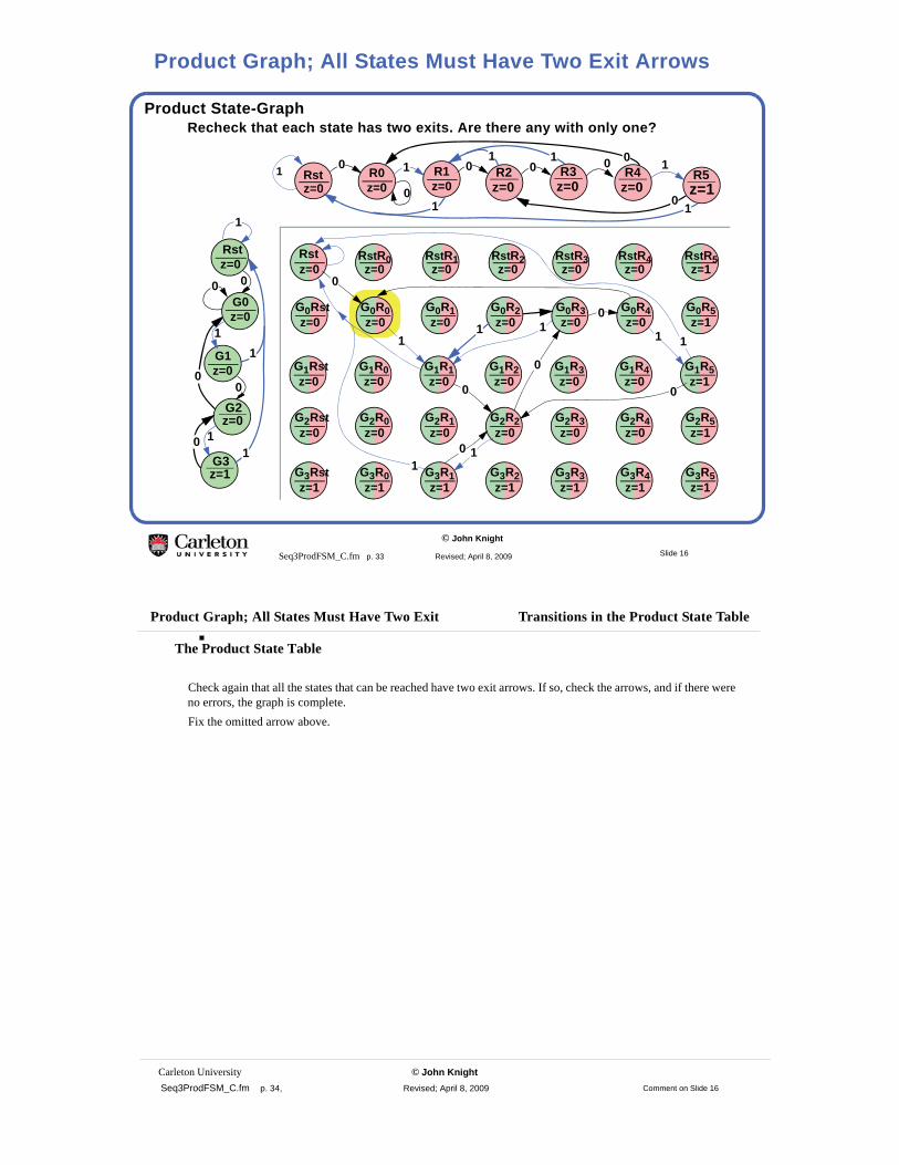
Product State-Graph
0
Recheck that each state has two exits. Are there any with only one?
Rstz=0
G0Rstz=0
G2Rstz=0
G3Rstz=1
Rstz=0
R0z=0
R2z=0
R1z=0
R3z=0
0R4
z=01
R5z=1
1
1 10
0 01 1 0
G1Rstz=0
RstR0z=0
G0R0z=0
G2R0z=0
G3R0z=1
G1R0z=0
G0R1z=0
G2R1z=0
G3R1z=1
G1R1z=0
G0R2z=0
G2R2z=0
G3R2z=1
G1R2z=0
G0R3z=0
G2R3z=0
G3R3z=1
G1R3z=0
G0R4z=0
G2R4z=0
G3R4z=1
G1R4z=0
G0R5z=1
G2R5z=1
G3R5z=1
G1R5z=1
RstR1z=0
RstR2z=0
RstR3z=0
RstR4z=0
RstR5z=1
1
0
0
1
1
0
0
0
1
0
0
1
1
11
Rstz=0
G2z=0
G1z=0
G0z=0
G3z=1
0
0
1
11
1
0
1
0
0
Slide 16
Product Graph; All States Must Have Two Exit Arrows
Carleton University © John Knight Seq3ProdFSM_C.fm p. 34, Revised; April 8, 2009
Product Graph; All States Must Have Two Exit Transitions in the Product State Table
The Product State Table
Check again that all the states that can be reached have two exit arrows. If so, check the arrows, and if there were no errors, the graph is complete.Fix the omitted arrow above.
Comment on Slide 16

© John Knight
Seq3ProdFSM_C.fm p. 35 Revised; April 8, 2009
A Moore “010001” or “0101” Sequence Detector with Overlap
0
0
The final state graph
Rstz=0
G0Rstz=0
G2Rstz=0
G3Rstz=1
Rstz=0
R0z=0
R2z=0
R1z=0
R3z=0
0R4
z=01
R5z=1
1
1 10
0 01 1 0
Rstz=0
G2z=0
G1z=0
G0z=0
G3z=1
0
0
1
11
1
0
1
0
0
G1Rstz=0
RstR0z=0
G0R0z=0
G2R0z=0
G3R0z=1
G1R0z=0
G0R1z=0
G2R1z=0
G3R1z=1
G1R1z=0
G0R2z=0
G2R2z=0
G3R2z=1
G1R2z=0
G0R3z=0
G2R3z=0
G3R3z=1
G1R3z=0
G0R4z=0
G2R4z=0
G3R4z=1
G1R4z=0
G0R5z=1
G2R5z=1
G3R5z=1
G1R5z=1
RstR1z=0
RstR2z=0
RstR3z=0
RstR4z=0
RstR5z=1
1
0
0
1
0
1
11
1
1
0
0
0
0
1
1
Slide 17
The Final Product State Graph
Carleton University © John Knight Seq3ProdFSM_C.fm p. 36, Revised; April 8, 2009
The Final Product State Graph The Final Product State Graph.
The Final Product State Graph.CommentsHere the final state graph has eight states requiring 3 flip-flopsIf one had used two separate machines and ORed their outputs, this would have worked, but it would have required 3 flip flops for the five state machine, and 3 more for the seven state machine for a total of 6 flip-flops.Also, if a shift register machine had been used, it would have had to have a flip-flop for each bit of the longest input sequence, or 6 flip-flops.
Comment on Slide 17

© John Knight
Seq3ProdFSM_C.fm p. 37 Revised; April 8, 2009
Design of FSM from Word Description
Wpsh
A One Pulse-Per-Push Circuit (OPP)
- may last many clock cycles.
A pulse which:
Specification
Step 1
Input X
- always overlaps at least one clock edge
OutputMealy output A
An output which:
- finishes at the next clock edge.
An output which:Moore output B
- starts when the input starts
- starts at the next clock edge- finishes one clock cycle later.
OPPX A(Mealy)
CLK
RST
B(Moore)
A(Mealy)
Block diagram, waveforms. Step 2
State graph x=1
WrlsA=0x=0
x=1x=0
Wait for X Wait for X
WrlsWpsh WrlsState
- Add state to waveforms- State changes only at clock edge- Mealy output may change when x changes
Machine With Mealy Output
B(Moore)
X
CLK
+V
pushbutton
WpshA=x
if x; A=1if x; A=0
(Moore)Wrls Wpsh
(wait for push) (wait for release)
Slide 18
A One Pulse Per Push Circuit; Mealy Design
Carleton University © John Knight Seq3ProdFSM_C.fm p. 38, Revised; April 8, 2009
A One Pulse Per Push Circuit; Mealy Design The Final Product State Graph.
Design of OPP1 MachineAt the Start of the Design, Choose Whether You Want Mealy or Moore Outputs
This was discussed near the end of the last section. One important reason for this circuit is given below.Duration of outputThe Moore output always lasts a full clock cycle.The Mealy output can be much less than a clock cycle. Its length depends on how far along in the cycle the input X changed. If the input comes late, the Mealy output can be very short, maybe too short.2
Input Push ButtonsThe push button is connected so pushing it sends out a “1” signal. Here we assume the signal does not bounce. This might be true if a capacitor is connected to hold the last voltage value when for the short time the button is in between the contacts.A more reliable debounce circuit was give in the Section on Latches and Flip Flops. and is repeated on the right.
1. In Ontario Canada, OPP stands for Ontario Provincial Police. There is no connection between them and this circuit.2. In real circuits inputs are sent through a single flip-flop before being allowed to enter the OPP circuit. This is discussed in the next course, ELEC 3500, under the topic “Asynchronous Inputs to Synchronous Circuits.”
+V
R
S
PUSH
SET
RESET
+V
PUSH
Comment on Slide 18
© John Knight
Seq3ProdFSM_C.fm p. 39 Revised; April 8, 2009
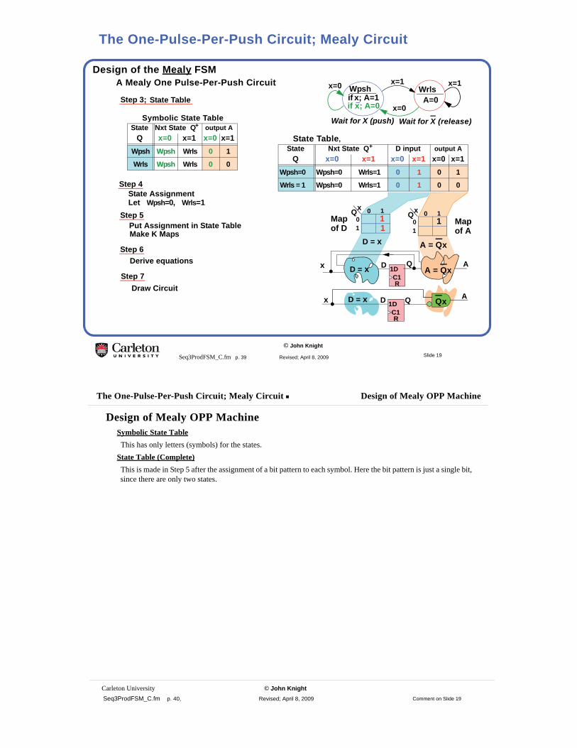
Design of the Mealy FSMA Mealy One Pulse-Per-Push Circuit
Step 4State Assignment
Step 5
State Table, State Nxt State Q+ D input output A
Q x=0 x=1 x=0 x=1 x=0 x=1Wpsh=0 Wpsh=0 Wrls=1 0 1 0 1
Wrls = 1 Wpsh=0 Wrls=1 0 1 0 0
Q1
x0
0 1
1Map
D = x
1DC1R
x Q AD
of D
A = Qx
Symbolic State Table State Nxt State Q+ output A
Q x=0 x=1 x=0 x=1Wpsh Wpsh Wrls 0 1
Wrls Wpsh Wrls 0 0
Step 3; State Table
x=1WrlsWpsh
if x; A=0if x; A=1 A=0
x=0
x=1x=0
Wait for X (push) Wait for X (release)
Q1
x0
0 1
1Map of A1
Let Wpsh=0, Wrls=1
Put Assignment in State TableMake K Maps
Derive equationsStep 6
Step 7Draw Circuit
D = x Qx
1DC1R
x QD AD = x A = Qx
Slide 19
The One-Pulse-Per-Push Circuit; Mealy Circuit
Carleton University © John Knight Seq3ProdFSM_C.fm p. 40, Revised; April 8, 2009
The One-Pulse-Per-Push Circuit; Mealy Circuit Design of Mealy OPP Machine
Design of Mealy OPP MachineSymbolic State TableThis has only letters (symbols) for the states.
State Table (Complete)This is made in Step 5 after the assignment of a bit pattern to each symbol. Here the bit pattern is just a single bit, since there are only two states.
Comment on Slide 19

© John Knight
Seq3ProdFSM_C.fm p. 41 Revised; April 8, 2009
Design Moore FSM from Word Description
SpB=1
Sp
A Moore One Pulse-Per-Push Circuit
Step 1X
B(Moore)
Block diagram.
Step 2State graph
SwB=0
x=0
x=0Wait for X
SpSw Snx SwState- Add state to waveforms- State changes only after clock edge
SnxP=0
wait forgot X
x=1
Sw
x=1
x=0
x=1
Symbolic State Table State Nxt State Q+ output
Q x=0 x=1 BSw Sw Sp 0
Sp Sw Snx 1
Snx Sw Snx 0
Step 3; State Table
Step 4State Assignment
Step 5Let Sw=00, Sp=11, Snx=01
Put Assignment in State TableMake K Maps
State Table State Nxt State Q+ output
Q x=0 x=1 BSw=00 Sw=00 Sp=11 0
Sp=11 Sw=00 Snx=01 1
Snx=01 Sw=00 Snx=01 0
Must change to K-map order
Draw Moore waveforms.
OPPX
CLK
RST
B
send Pulse Not X
pulse pulse
Slide 20
The One-Pulse-Per-Push Circuit; Moore Design
Carleton University © John Knight Seq3ProdFSM_C.fm p. 42, Revised; April 8, 2009
The One-Pulse-Per-Push Circuit; Moore Design Moore OPP
Moore OPP
Compare Moore With Mealy• Moore has an extra state• The extra state usually means slightly more hardware.
Going from two states to three requires another flip-flop.• Moore output is delayed till the next clock period after the Mealy output.• Moore outputs are close to a full clock cycle wide.1
1. If there is a lot of logic in the output circuitry, this may be reduced, but it will be wider than a similar Mealy output.
Comment on Slide 20

© John Knight
Seq3ProdFSM_C.fm p. 43 Revised; April 8, 2009
A Moore One Pulse-Per-Push Circuit
Step 5Put state table in K-map order
Make K Maps
Derive equationsStep 6
Step 7Draw circuit
State Table State Nxt St Q+P+=DQDP output Q,P x=0 x=1 B
Sw=00 Sw=00 Sp=01 0
Sp=01 Sw=00 Sn=11 0
Sn=11 Sw=00 Sn=11 1
d
00011110
0 1X
QP
dQP
100d
000
DQ = x·P
0
0
0 1
01
0
1
1
1d d
0
0
0
00011110
0 1X
QP
dQP
111d
000
DP = x
00011110
QP
dQP1
00
B = Q
d d
1DC1R
x P
B1DC1R
Q xP
DP
DQ
Slide 21
The One-Pulse-Per-Push Circuit; Moore Circuit
Carleton University © John Knight Seq3ProdFSM_C.fm p. 44, Revised; April 8, 2009
The One-Pulse-Per-Push Circuit; Moore Circuit Moore OPP
Moore OPPNotice we used an extra flip-flop. Going from one to two looks like a large increase. However when a machine has 8 flip-flops, going from Mealy to Moore would at most increase the number of flip-flops by one.
Comment on Slide 21

© John Knight
Seq3ProdFSM_C.fm p. 45 Revised; April 8, 2009
Making Product Graphs1. Check that each state has two outputs (for a one input machine).
2. The most mistakes are made when calculating where to go when off the main sequence.
3. Don’t look at states that cannot be reached from RESET.
R0z=0
Wait for “1”
Output 1
Rec 10R5z=xR2
z=0
x=1Rec 101
R1z=0
Rec 1x=1 x=0
x=0x=1
x=1x=0x=0
if x=1
The red lines are the hardest
Slide 22
Summary and Common Errors
Carleton University © John Knight Seq3ProdFSM_C.fm p. 46, Revised; April 8, 2009
Summary and Common Errors Moore OPP
When constructing a state graph, one should check for extra states.This is done in the next chapter.This example for the 1011 1101 machine done here close to the design of the machine.
Comment on Slide 22

© John Knight
Seq3ProdFSM_C.fm p. 47 Revised; April 8, 2009
Checking the 1011 1101 State Graph tor Unneeded States
S0G1G2G5S4G6
S0G2S0G2G6S0
G1G3G5G3G3G5
0 000
0 00 10 00 1
G1
G2
G5
G3
G6
G2
S0
G2
G6
S0
G3
G5
G3
G3
G5
G1G0R0 G2 G5 G3S0 G1
S0 G1
S0 G1
S0 G1
S0 G1
G2G3
G2G3
G2G3
G2G3S0 G5
G2 G3
G6 G3G6 G3G6 G3
G2 G3
S0 G5
S0 G5
S0 G5
G2 G3
G2 G3S0 G5 S0 G5S0 G5 S0 G5
G6 G3
No Mergers Possible
State NextState Outputs
Checking for possible state mergers.
Don’t read this until you read the chapter on state merging.
Some states may be redundantNormally done for a FSM design.
G0R0z=0
Wait fora “1”
G1R1z=0
Got “1”Output 1 if x=1
Got “10”
x=1
x=0
x=1
G1R5z = x
G0R2z=0
x=1
Got “101”
G3R1z=0
Got “11”
x=0
x=1
Output 1 if x=1
G0R0z = x
Got “110”
x=1
x=0
x=0
x=1
x=0
x=0
Slide 23
Check for Extra States in Circuit of Slide 8
Carleton University © John Knight Seq3ProdFSM_C.fm p. 48, Revised; April 8, 2009
Check for Extra States in Circuit of Slide 8 Moore OPP
Comment on Slide 23
© John Knight
Seq3ProdFSM_C.fm p. 49 Revised; April 8, 2009
G0R0z=0
Wait fora “1”
G1R1z=0
Got “1”Output 1 if x=1
Got “10”
x=1
x=0
x=1
G1R5z = x
G0R2z=0
x=1
Got “101”
G3R1z=0
Got “11”
x=0
x=1
Output 1 if x=1
G6R2z = x
Got “110”
x=1
x=0
x=0
x=1
x=0
x=0
G0R0z=0
G1R1z=0
G3R1z=0
G0R2z=0
G6R2z=x
G1R5z=x
1 0
1
0
1
10
0
0
0
1
1
G1R2z=0
G1R0z=0
G6R0z=x
G3R0z=0
G6R1z=x
G3R2z=0
G0R5z=x
G6R5z=x
G3R5z=x
G0R1z=0
Slide 24
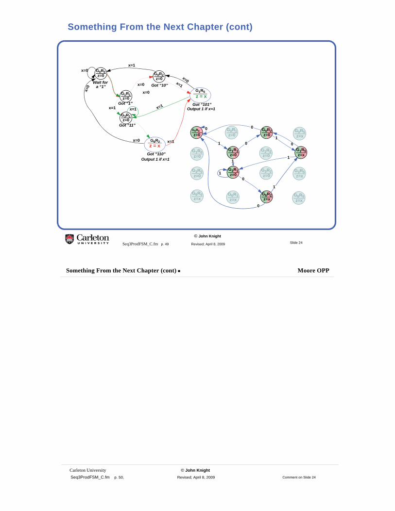
Something From the Next Chapter (cont)
Carleton University © John Knight Seq3ProdFSM_C.fm p. 50, Revised; April 8, 2009
Something From the Next Chapter (cont) Moore OPP
Comment on Slide 24

© John Knight
Seq3ProdFSM_C.fm p. 51 Revised; April 8, 2009
Carleton University © John Knight Seq3ProdFSM_C.fm p. 52, Revised; April 8, 2009
Something From the Next Chapter (cont) Moore OPP
Comment on Slide 25