digital amplifier ultrasonic sensor e4c-uda
TRANSCRIPT
CSM_E4C-UDA_DS_E_12_3
1
Digital Amplifier Ultrasonic Sensor
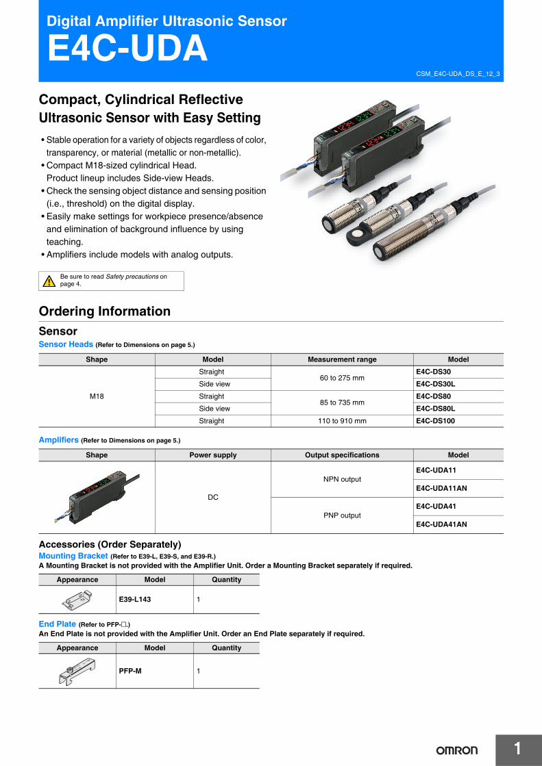
E4C-UDACompact, Cylindrical Reflective Ultrasonic Sensor with Easy Setting• Stable operation for a variety of objects regardless of color,
transparency, or material (metallic or non-metallic). • Compact M18-sized cylindrical Head.
Product lineup includes Side-view Heads. • Check the sensing object distance and sensing position
(i.e., threshold) on the digital display.• Easily make settings for workpiece presence/absence
and elimination of background influence by using teaching.
• Amplifiers include models with analog outputs.
Ordering InformationSensorSensor Heads (Refer to Dimensions on page 5.)
Amplifiers (Refer to Dimensions on page 5.)
Accessories (Order Separately)Mounting Bracket (Refer to E39-L, E39-S, and E39-R.) A Mounting Bracket is not provided with the Amplifier Unit. Order a Mounting Bracket separately if required.
End Plate (Refer to PFP-@.)An End Plate is not provided with the Amplifier Unit. Order an End Plate separately if required.
Shape Model Measurement range Model
M18
Straight60 to 275 mm
E4C-DS30
Side view E4C-DS30L
Straight85 to 735 mm
E4C-DS80
Side view E4C-DS80L
Straight 110 to 910 mm E4C-DS100
Shape Power supply Output specifications Model
DC
NPN outputE4C-UDA11
E4C-UDA11AN
PNP outputE4C-UDA41
E4C-UDA41AN
Appearance Model Quantity
E39-L143 1
Appearance Model Quantity
PFP-M 1
Be sure to read Safety precautions on page 4.

E4C-UDA
2
Ratings and SpecificationsSensor Heads
* This value is the average number of operations set to 256.
Amplifiers
* Value one hour after the product is turned ON. External disturbances, however, sometimes cause minute outputs.
Item Model E4C-DS30 E4C-DS30L E4C-DS80 E4C-DS80L E4C-DS100Measurement range 60 to 275 mm 85 to 735 mm 110 to 910 mm
Standard sensing object 100 ✕ 100 mm SUS flat plate
Near distance dead band 0 to 50 mm 0 to 70 mm 0 to 90 mm
Ultrasonic oscillation frequency Approx. 390 kHz Approx. 255 kHz
Response speed * 30 ms 100 ms 125 ms
Ambient temperature range Operating: −25 to +70°C, Storage: −40 to +85°C (with no icing or condensation)
Ambient humidity range Operating and storage: 35% to 85% (with no condensation)
Insulation resistance 50 MΩ min. (at 500 VDC)
Dielectric strength 1,000 VAC, 50/60 Hz for 1 min
Vibration resistance 10 to 55 Hz, 1.5-mm double amplitude, 2 hours each in X, Y, and Z directions
Shock resistance 500 m/s2, 3 times each in X, Y and Z directions
Enclosure rating IP65
Indicator (Yellow) Lit: Sensor within sensing range(Green) Lit: Power indicator
(Yellow) Lit: Sensor within sensing range
Weight Approx. 150 g Approx. 170 g
Materials Case: Nickel-plated brass, Oscillator surface: Glass epoxy resin and polyurethane
Accessories Instruction Manual, XS2F-D523-D80-A (Cable length: 2 m), XN2A-1430
Model E4C-UDA11 E4C-UDA41 E4C-UDA11AN E4C-UDA41AN
Item Type Twin Output Models Analog Output ModelsOutput configuration NPN output PNP output NPN output PNP output
Connection method Pre-wired
Supply voltage 12 to 24 VDC ±10%, ripple 10% max.
Current consumption 80 mA max.
Control output NPN open collector (26.4 VDC max.),Load current: 50 mA max., Residual voltage: 1 V max.
Timer OFF/OFF-delay/ON-delay/one-shot
Timer time 1 ms to 5 s
Analog output
Connected load --- Voltage output (1 to 5 VDC)
Output form --- 10 kΩ min.
Resolution --- 1.0% F.S.
Temperature characteristics --- 0.3% F.S./°C
Repeat accuracy --- 2.0% F.S. *Linearity --- Within ±2% F.S.
Protective circuit Power supply reverse polarity protection, output short-circuit protection
Ambient temperature range Operating: −25 to +55°C, Storage: −30 to +70°C (with no icing or condensation)
Ambient humidity range Operating and storage: 35% to 85% (with no condensation)
Insulation resistance 20 MΩ min. (at 500 VDC)
Dielectric strength 1,000 VAC, 50/60 Hz for 1 min
Vibration resistance 10 to 55 Hz, 1.5-mm double amplitude, 2 hours each in X, Y, and Z directions
Shock resistance 500 m/s2, 3 times each in X, Y and Z directions
Enclosure rating IP 50
Materials Case: PBT (polybutylene terephthalate), Cover: Polycarbonate
Weight (packed state) Approx. 100 g
Accessories Instruction Manual
3
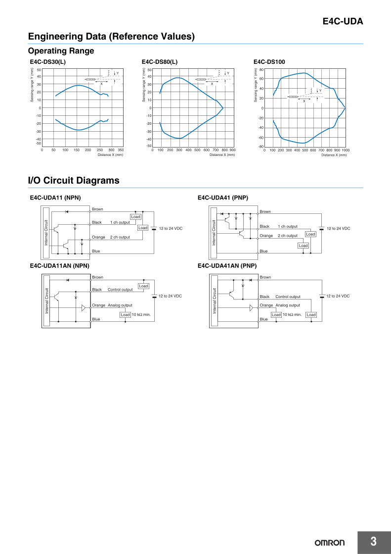
E4C-UDAEngineering Data (Reference Values)Operating Range
I/O Circuit Diagrams
E4C-DS30(L) E4C-DS80(L) E4C-DS100
E4C-UDA11 (NPN) E4C-UDA41 (PNP)
E4C-UDA11AN (NPN) E4C-UDA41AN (PNP)
50 100 150 200 250 300 3500
-50
50
40
30
20
10
0
-10
-20
-30
-40
Y
X
Distance X (mm)
Sen
sing
ran
ge Y
(m
m)
100 200 300 400 500 600 700 9008000-50
50
40
30
20
10
0
-10
-20
-30
-40
Y
X
Distance X (mm)
Sen
sing
ran
ge Y
(m
m)
100 200 300 400 500 600 700 10009008000-80
-60
-40
-20
80
60
40
20
0
Y
X
Distance X (mm)
Sen
sing
ran
ge Y
(m
m)
Inte
rnal
Circ
uit
Brown
Black
Orange
Blue
1 ch output
2 ch output
12 to 24 VDC
Load
Load
Inte
rnal
Circ
uit
Brown
Black
Orange
Blue
1 ch output
2 ch output
12 to 24 VDC
Load
Load
Inte
rnal
Circ
uit
Brown
Black
Orange
Blue
Control output
Analog output
12 to 24 VDC
Load
Load 10 kΩ min. Inte
rnal
Circ
uit
Brown
Black
Orange
Blue
Control output
Analog output
12 to 24 VDC
LoadLoad 10 kΩ min.

4
E4C-UDASafety precautionsRefer to Warranty and Limitations of Liability.
This product is not designed or rated for ensuring safety of persons either directly or indirectly.Do not use it for such purposes.
Do not use the product in atmospheres or environmets that exceed product ratings.
• Separate the Sensor wiring from power supply and high-voltage lines. If Sensor wiring is placed together with or in the same duct as power supply or high-voltage lines, inductance may cause malfunction or damage to the Sensor.
• The extended cable length must be no more than 10 m. To extend the cable length, use 0.3 mm2 cable.
• Detection will be possible 200 ms or longer after the power supply is turned ON. If separate power supplies are used for the load and the Sensor, turn ON the power supply to the Sensor first.
• Make sure that the cover to the Amplifier is in place before using the Sensor.
• If a writing error occurs (ERR/EEP will flash on the display) due to noise resulting from turning OFF the power supply, static electricity, or other cause, initialize the settings using the SET switch on the Amplifier.
• Depending on the application environment, some time may be required for the displayed distance to stabilize after turning ON the power supply.
• Output pulses may be generated when the power supply to the Amplifier is turned OFF. Turn OFF the load or the power supply to the load before turning OFF the Sensor.
• Do not use thinners, benzine, acetone, kerosene, or any other petroleum solvents to clean the Sensor or Amplifier.
• Turn OFF the power supply before connecting or disconnecting the Sensor Head. Use only an E4C Sensor Head. The product may be damaged if any other Sensor Head is connected.
• The distance displayed on the Amplifier may be different from values obtained with tape measures or other devices. To adjust the displayed distance, use the scaling function.
Mutual InterferenceWhen installing two or more Sensor Heads side by side, ensure that the minimum distances given in the following table are maintained.
WARNING
Precautions for Correct Use
Y
Model YE4C-DS30/-DS30L 300 mm min.E4C-DS80/-DS80L 800 mm min.E4C-DS100 1,000 mm min.
* These distances are the separations at the maximum measurement distances. The degree of effect depends on the equipment and surrounding conditions. Check the degree of effect after you install the Sensor Heads in your operating environment.

5
E4C-UDADimensionsSensor Heads
Amplifiers
(Unit: mm)Tolerance class IT16 applies to dimensions in this data sheet unless otherwise specified.
Indicator *
Two clamping nuts
24.5
39.210
50.2
M18 × 1 M12 × 1
24
4
(83)40.7
14.9 dia.
(R24)
4-mm diameter vinyl-insulated round cable with 4 conductors(cross-sectional of conductors: 0.2 mm2,insulation system: 1.1-mm diameter), Standard length: 2 m
E4C-DS30E4C-DS80
* Sensor within sensing range (yellow), Power indicator (green)
Indicator *
Two clamping nuts
24
24.5
39.210
67.7
4
M12 × 1M18 × 1
40.7
(100)
14.9 dia.
4-mm diameter vinyl-insulated round cable with 4 conductors(cross-sectional of conductors: 0.2 mm2,insulation system: 1.1-mm diameter), Standard length: 2 m
(R24)
E4C-DS30LE4C-DS80L
* Sensor within sensing range (yellow), Power indicator (green)
4 Indicator *Two clamping nuts
24
48
7410
85
40.7
(117)
M12 × 1
14.9 dia.
4-mm diameter vinyl-insulated round cable with 4 conductors(cross-sectional of conductors: 0.2 mm2,insulation system: 1.1-mm diameter), Standard length: 2 m
(R24)
M18 × 1
E4C-DS100
* Sensor within sensing range (yellow)
(2)
(1)
M12
14.9
dia
.
40.7
2000
54 di
a.
Sensor-Amplifier connection cable (included with Sensor)
Products Name Model(1) Standard Cable (2m) XS2F-D523-D80-A
(2) Connector XN2A-1430
2.5 50.3
768.1
24.7
9.9
3.4
32
36.7
32
12.5013.8
10
38.8
18.15
21.1
35.8
3.9×3=11.7
3.9×3=11.7
4-mm diameter vinyl-insulated round cable with 4 conductors(cross-sectional of conductors: 0.2 mm2,insulation system: 1.1-mm diameter), Standard length: 2 m
E4C-UDA11E4C-UDA41
2.5 50.3
768.1
24.7
9.9
3.4
32
36.7
32
12.5013.8
10
38.8
18.15
21.13.9×3=11.7
3.9×3=11.7
4-mm diameter vinyl-insulated round cable with 4 conductors(cross-sectional of conductors: 0.2 mm2,insulation system: 1.1-mm diameter), Standard length: 2 m
E4C-UDA11ANE4C-UDA41AN

Terms and Conditions Agreement Read and understand this catalog. Please read and understand this catalog before purchasing the products. Please consult your OMRON representative if you have any questions or comments. Warranties. (a) Exclusive Warranty. Omron’s exclusive warranty is that the Products will be free from defects in materials and workmanship for a period of twelve months from the date of sale by Omron (or such other period expressed in writing by Omron). Omron disclaims all other warranties, express or implied. (b) Limitations. OMRON MAKES NO WARRANTY OR REPRESENTATION, EXPRESS OR IMPLIED, ABOUT NON-INFRINGEMENT, MERCHANTABILITY OR FITNESS FOR A PARTICULAR PURPOSE OF THE PRODUCTS. BUYER ACKNOWLEDGES THAT IT ALONE HAS DETERMINED THAT THE PRODUCTS WILL SUITABLY MEET THE REQUIREMENTS OF THEIR INTENDED USE. Omron further disclaims all warranties and responsibility of any type for claims or expenses based on infringement by the Products or otherwise of any intellectual property right. (c) Buyer Remedy. Omron’s sole obligation hereunder shall be, at Omron’s election, to (i) replace (in the form originally shipped with Buyer responsible for labor charges for removal or replacement thereof) the non-complying Product, (ii) repair the non-complying Product, or (iii) repay or credit Buyer an amount equal to the purchase price of the non-complying Product; provided that in no event shall Omron be responsible for warranty, repair, indemnity or any other claims or expenses regarding the Products unless Omron’s analysis confirms that the Products were properly handled, stored, installed and maintained and not subject to contamination, abuse, misuse or inappropriate modification. Return of any Products by Buyer must be approved in writing by Omron before shipment. Omron Companies shall not be liable for the suitability or unsuitability or the results from the use of Products in combination with any electrical or electronic components, circuits, system assemblies or any other materials or substances or environments. Any advice, recommendations or information given orally or in writing, are not to be construed as an amendment or addition to the above warranty. See http://www.omron.com/global/ or contact your Omron representative for published information. Limitation on Liability; Etc. OMRON COMPANIES SHALL NOT BE LIABLE FOR SPECIAL, INDIRECT, INCIDENTAL, OR CONSEQUENTIAL DAMAGES, LOSS OF PROFITS OR PRODUCTION OR COMMERCIAL LOSS IN ANY WAY CONNECTED WITH THE PRODUCTS, WHETHER SUCH CLAIM IS BASED IN CONTRACT, WARRANTY, NEGLIGENCE OR STRICT LIABILITY. Further, in no event shall liability of Omron Companies exceed the individual price of the Product on which liability is asserted. Suitability of Use. Omron Companies shall not be responsible for conformity with any standards, codes or regulations which apply to the combination of the Product in the Buyer’s application or use of the Product. At Buyer’s request, Omron will provide applicable third party certification documents identifying ratings and limitations of use which apply to the Product. This information by itself is not sufficient for a complete determination of the suitability of the Product in combination with the end product, machine, system, or other application or use. Buyer shall be solely responsible for determining appropriateness of the particular Product with respect to Buyer’s application, product or system. Buyer shall take application responsibility in all cases. NEVER USE THE PRODUCT FOR AN APPLICATION INVOLVING SERIOUS RISK TO LIFE OR PROPERTY OR IN LARGE QUANTITIES WITHOUT ENSURING THAT THE SYSTEM AS A WHOLE HAS BEEN DESIGNED TO ADDRESS THE RISKS, AND THAT THE OMRON PRODUCT(S) IS PROPERLY RATED AND INSTALLED FOR THE INTENDED USE WITHIN THE OVERALL EQUIPMENT OR SYSTEM. Programmable Products. Omron Companies shall not be responsible for the user’s programming of a programmable Product, or any consequence thereof. Performance Data. Data presented in Omron Company websites, catalogs and other materials is provided as a guide for the user in determining suitability and does not constitute a warranty. It may represent the result of Omron’s test conditions, and the user must correlate it to actual application requirements. Actual performance is subject to the Omron’s Warranty and Limitations of Liability. Change in Specifications. Product specifications and accessories may be changed at any time based on improvements and other reasons. It is our practice to change part numbers when published ratings or features are changed, or when significant construction changes are made. However, some specifications of the Product may be changed without any notice. When in doubt, special part numbers may be assigned to fix or establish key specifications for your application. Please consult with your Omron’s representative at any time to confirm actual specifications of purchased Product. Errors and Omissions. Information presented by Omron Companies has been checked and is believed to be accurate; however, no responsibility is assumed for clerical, typographical or proofreading errors or omissions.
2020.7
In the interest of product improvement, specifications are subject to change without notice.
OMRON Corporation Industrial Automation Company http://www.ia.omron.com/
(c)Copyright OMRON Corporation 2020 All Right Reserved.

Mouser Electronics
Authorized Distributor
Click to View Pricing, Inventory, Delivery & Lifecycle Information: Omron:
E4C-UDA11 E4C-UDA11AN E4C-UDA41 E4C-UDA41AN