digi fox manual eng v3.2
TRANSCRIPT
Version 1


I English
II Deutsch


Version 3.2 – eng - 2013/01
Please note:
New Spreading Feature!


Table of Contents
1 Receiver ..............................................................................................................................9
1.1 Operation / Optical Signals ...........................................................................................9
1.2 Receiver Connections .................................................................................................11
2 Transmitter .......................................................................................................................12
2.1 Operation / Optical Signals .........................................................................................12
2.2 Spreading the Lens Scales at Chrosziels Lens Control Systems ................................13
3 Technical Information .......................................................................................................15
3.1 Weight and Dimensions ..............................................................................................15
3.2 Electrical Features .....................................................................................................15
3.3 Pin Assignments.........................................................................................................16
3.4 Electronic calibration of the transmitter’s hand wheel - factory setup.......................18
4 Declarations of conformity ................................................................................................19


Details 9
1 Receiver Figure 1 - Front Side of Receiver
1.1 Operation / Optical Signals
1.1.1 Connector „MOTOR“ (Lemo 8 pin)
This socket connects external so-called digital servo motors with incremental encoder,
such as motors from the manufacturers Hedén (M26/21VE), Scorpio, Preston & Betz Tools.
1.1.2 Connector „LENS FOCUS, CAM ON/OFF“ (Hirose 12 pin)
For the connection of internal focus servo motors of ENG-lenses like Fujinon or Canon by
means of special adaptor a cable. Also connects to the "Focus Control" socket of Panasonic
camcorders DVX / HVX – types. This connector also controls the start/stop-function of video
and film cameras. If ENG-lenses are connected to the receiver it will be powered through
this connector and the lens outlet (10-17V).
1.1.3 Connector „POWER IN, CAM ON/OFF“ (Hirose 4 pin)
Used for the connection of an external power supply (voltage 10-35V). It is needed for the
operation of external motors or if the receiver controls Panasonic camcorders. It also
controls the start/stop-function of film- and video cameras.
1.1.4 Connector „ANTENNA“
Used for the connection of the receiver’s antenna, 50 Ohm, for 400 MHz band. In case of
extremely bad reception due to i.e. broadband interferences, the connection between the
transmitter and the receiver may be made of a standard BNC cable.
1.1.5 Button „ADJUST END STOPS“
When an external motor is connected, this button starts the adjust mode for the end stops
of the lens. If calibration of an external motor shall be performed please proceed as
follows: press the button once – the LED “FN” starts flashing fast. The motor starts the
10 Details
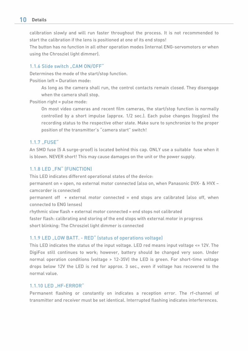
calibration slowly and will run faster throughout the process. It is not recommended to
start the calibration if the lens is positioned at one of its end stops!
The button has no function in all other operation modes (internal ENG-servomotors or when
using the Chrosziel light dimmer).
1.1.6 Slide switch „CAM ON/OFF“
Determines the mode of the start/stop function.
Position left = Duration mode:
As long as the camera shall run, the control contacts remain closed. They disengage
when the camera shall stop.
Position right = pulse mode:
On most video cameras and recent film cameras, the start/stop function is normally
controlled by a short impulse (approx. 1/2 sec.). Each pulse changes (toggles) the
recording status to the respective other state. Make sure to synchronize to the proper
position of the transmitter’s “camera start” switch!
1.1.7 „FUSE“
An SMD fuse (5 A surge-proof) is located behind this cap. ONLY use a suitable fuse when it
is blown. NEVER short! This may cause damages on the unit or the power supply.
1.1.8 LED „FN“ (FUNCTION)
This LED indicates different operational states of the device:
permanent on = open, no external motor connected (also on, when Panasonic DVX- & HVX –
camcorder is connected)
permanent off + external motor connected = end stops are calibrated (also off, when
connected to ENG lenses)
rhythmic slow flash + external motor connected = end stops not calibrated
faster flash: calibrating and storing of the end stops with external motor in progress
short blinking: The Chrosziel light dimmer is connected
1.1.9 LED „LOW BATT. - RED“ (status of operations voltage)
This LED indicates the status of the input voltage. LED red means input voltage <= 12V. The
DigiFox still continues to work; however, battery should be changed very soon. Under
normal operation conditions (voltage > 12-35V) the LED is green. For short-time voltage
drops below 12V the LED is red for approx. 3 sec., even if voltage has recovered to the
normal value.
1.1.10 LED „HF-ERROR“
Permanent flashing or constantly on indicates a reception error. The rf-channel of
transmitter and receiver must be set identical. Interrupted flashing indicates interferences.
Details 11
1.1.11 Cover on housing bottom
Under the cover the dip switches are located for selecting the receiver channels. Four
switch positions allow for setting of 16 different transmission channels.
1.1.12 Switch „Motor Power – Low High“
This switch is placed behind the cover on the back of the housing. It allows to adjust the
maximal power for external digital motors. In position “low” the force and thus power for
the motor driver is reduced to approx. 60 %. This selection is recommended for smooth-
running ENG lenses or in case of an insufficient power source for the receiver. In position
“high”, the motor driver provides maximal power to the external motor. This mode is
recommended for heavier film lenses and/or good power supplies. The motor then reacts
very dynamically due to the power reserves.
1.2 Receiver Connections
1.2.1 External Digital Motors
External digital motors (Hedén M26VE, Scorpio SB92, Preston (DM2) or Betz Tools BTM7)
are connected through the „AMOTD“-cable to the connector “MOTOR”. Power (10-35V) is
applied through the 4-Pin Hirose connector. Use power cables as listed in price list for
DigiFox. Do not use 24V power cables made for Genio and MagFox as the wiring is different!
For the CAM start/stop function the respective cables are connected to the 12pin Hirose
connector „LENS FOCUS - CAM ON/OFF“. It is possible to use a combined Power &
Start/Stop cable on the „POWER IN“ connector for appropriate cameras like Panavision
„PAN-A-P/CAM“.
1.2.2 Internal Servomotors of ENG-, EFP-, DV- and HDV- Lenses
To control ENG-lenses (without external motor) the existence of a focus motor in the servo
unit is required. DigiFox will be powered and does control the lens through the cables
„DFPMCD” (Canon digital), „DFPMCA“(Canon analog) or „DFPMF“(Fujinon) to the connector
“LENS FOCUS”. For the camera START/STOP function the respective cables are connected
to the 4Pin Hirose-connector „POWER IN- CAM ON/OFF“. No additional power supply is
required, as the receiver is powered through the lens. The connection of the Panasonic
DVX/HVX Camcorder is an exception. Power supply has to be made separately at connector
„POWER IN“(e.g. XLR4-AL). Focus control and Start/Stop function are done through the
connector „LENS FOCUS“ by using the cable „DFPMPVX“.
1.2.3 Chrosziel Light Dimmer for Standard Camera Light
The Chrosziel Light Dimmer for camera lights is connected through the connector
„MOTOR“. Power supply has to be feed through „POWER IN“.
Only operate the Light Dimmer at 12 – 15V.
12 Details
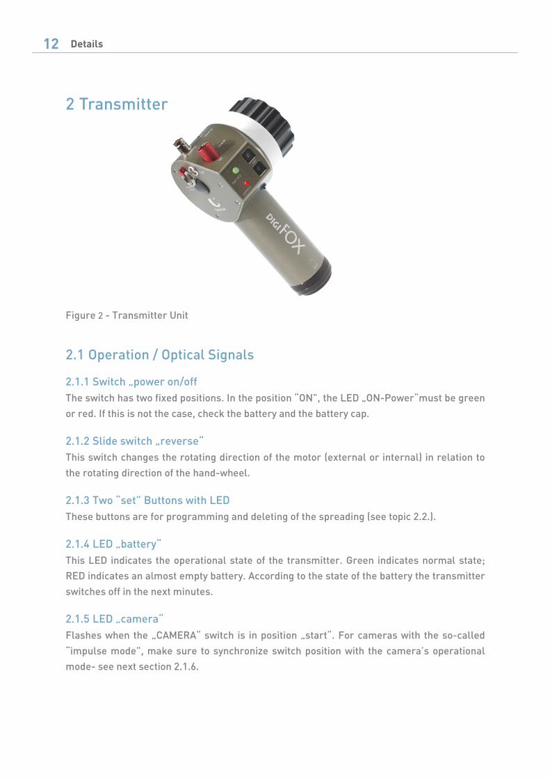
2 Transmitter Figure 2 - Transmitter Unit
2.1 Operation / Optical Signals
2.1.1 Switch „power on/off
The switch has two fixed positions. In the position “ON”, the LED „ON-Power“must be green
or red. If this is not the case, check the battery and the battery cap.
2.1.2 Slide switch „reverse“
This switch changes the rotating direction of the motor (external or internal) in relation to
the rotating direction of the hand-wheel.
2.1.3 Two “set” Buttons with LED
These buttons are for programming and deleting of the spreading (see topic 2.2.).
2.1.4 LED „battery“
This LED indicates the operational state of the transmitter. Green indicates normal state;
RED indicates an almost empty battery. According to the state of the battery the transmitter
switches off in the next minutes.
2.1.5 LED „camera“
Flashes when the „CAMERA“ switch is in position „start“. For cameras with the so-called
“impulse mode”, make sure to synchronize switch position with the camera’s operational
mode- see next section 2.1.6.

Details 13
2.1.6 Switch „camera start“:
Controls the Start/Stop function of the camera (see also topic 1.1.6 “Slide switch „CAM
ON/OFF“ at page 10)
2.1.7 Connector „light“
Connection for the Chrosziel LED- scale illumination (please use original accessories only!)
2.1.8 Cover “channel select”
The dip switches for selecting the transmitter channels are located under the cover. Four
switch positions result in 16 different transmission channels. Selection must be identical to
the receiver.
2.2 Spreading the Lens Scales at Chrosziels Lens Control Systems Before the procedure is described, one needs to understand the meaning of spreading and
how it works.
Please note, that the procedure explained below is a new feature existing on units delivered
since January 2013 only. Units delivered before Jan. 2013 can be updated with the current
software release at Chrosziel if required.
In normal modenormal modenormal modenormal mode (Spreading is off) (Spreading is off) (Spreading is off) (Spreading is off) the full rotation/movement of the hand wheel/slider
corresponds to 100% of the lens scale range between the two mechanical end stops.
In spreadspreadspreadspread m m m mode ode ode ode only a part of the lens scale corresponds to the full range of the hand
wheel/slider. This mode is useful if you want to adjust the lens very accurately in a specified
range. For example, the scale of the lens ranges from 0,3m to infinity, but you want to work
only from 20m to 30m and want to be very precise in this range. In this case, you would
spread this range to the full scale of the hand controller. The one end stop then
corresponds to 20m and the other to 30m.
Chrosziel Lens Control Systems allow the storing of two independenttwo independenttwo independenttwo independent spread settings
which can be switched off if not needed and recalled later on by simply pressing a button.
Two set buttons (A & B) are assigned to the hand wheel & slider.
Store a spreading:
- Hold one of the set buttons down (i.e. A), wait until the opposite LED (B) is flashing -
this will happen after 1 second.
- Keep button A pressed and move the hand wheel / slider in the desired range and
release button A. Button A will light permanently indicating that spreading A is
active now. Button B is off.
- In order to switch off spreading A, simply press button A shortly (less then 1 sec) No
LED is on.
- In order to recall spreading A, press button A shortly (less then 1 s) - LED A switches
on again

14 Details
- In order to store a second spreading, repeat the procedure with button B as
described for button A. Switch off and recall a spreading in the same manner by
pressing button B shortly.
Please also see following graphics.
Figure 1
Hint:
If applying a “zero” spreading (the hand wheel was not moved during the spreading
procedure), the recall of this spreading setup can be used as a kind of preset control for a
desired position.
Example: Drive lens ring to 30m and press button A for more than 1 second. Release button
A. Drive the lens ring to 20 m and hold down button B for more than 1 second. Release
button B. Do not turn the hand wheel.
Now the scale values 30m and 20m can be recalled instantly by pressing on Button A or B
once.
Full lens travel
Full lens travel
Scale travel on hand unit
Scale travel on hand unit
20m 30m
Chrosziel Aladin/DigiFox Electronic Spreading
Normal (1:1) Mode
0,3m Infinite
0% approx. 300° 100%
Spread Mode:
0,3m Infinte
0% approx. 300° 100%
Technical 15
3 Technical Information
3.1 Weight and Dimensions
3.2 Electrical Features
3.2.1 Transmitter
3.2.2 Receiver
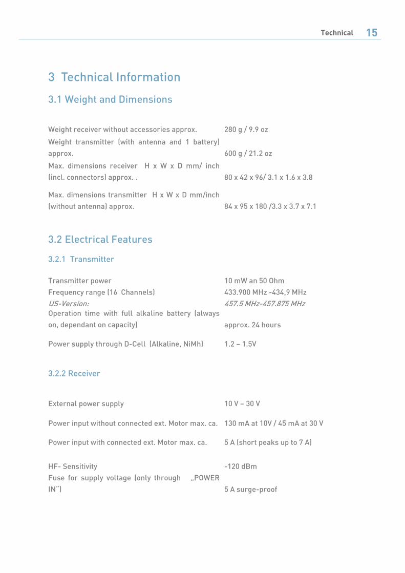
Weight receiver without accessories approx. 280 g / 9.9 oz
Weight transmitter (with antenna and 1 battery)
approx. 600 g / 21.2 oz
Max. dimensions receiver H x W x D mm/ inch
(incl. connectors) approx. . 80 x 42 x 96/ 3.1 x 1.6 x 3.8
Max. dimensions transmitter H x W x D mm/inch
(without antenna) approx. 84 x 95 x 180 /3.3 x 3.7 x 7.1
Transmitter power 10 mW an 50 Ohm
Frequency range (16 Channels)
US-Version:
433.900 MHz -434,9 MHz
457.5 MHz-457.875 MHz Operation time with full alkaline battery (always
on, dependant on capacity) approx. 24 hours
Power supply through D-Cell (Alkaline, NiMh) 1.2 – 1.5V
External power supply 10 V – 30 V
Power input without connected ext. Motor max. ca. 130 mA at 10V / 45 mA at 30 V
Power input with connected ext. Motor max. ca. 5 A (short peaks up to 7 A)
HF- Sensitivity -120 dBm
Fuse for supply voltage (only through „POWER
IN“) 5 A surge-proof

16 Technical
3.2.3 Table of used Frequencies
3.3 Pin Assignments
3.3.1 Connector “MOTOR“
Front View to connector
Type: Lemo EGG. 1B. 307
Pin 1: Motor –
Pin 2: Motor +
Pin 3: Encoder channel A
Pin 4: +5V
Pin 5: earth/ground
Pin 6: Encoder channel B
Pin 7: earth/ground
1
7
6
Frequencies
EU-Version US-Version
433.900 457.500
433.950 457.525
434.000 457.550
434.050 457.575
434.100 457.600
434.150 457.625
434.200 457.650
434.250 457.675
434.300 457.700
434.350 457.725
434.400 457.750
434.450 457.775
434.500 457.800
434.550 457.825
434.600 457.850
434.650 457.875
Positions of the code switches
on the rf-modules
Technical 17
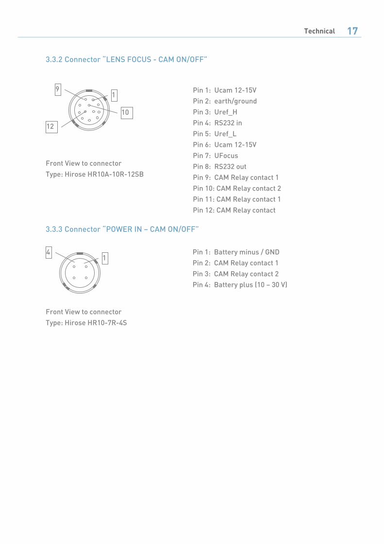
3.3.2 Connector “LENS FOCUS - CAM ON/OFF”
3.3.3 Connector “POWER IN – CAM ON/OFF”
Front View to connector
Type: Hirose HR10A-10R-12SB
Pin 1: Ucam 12-15V
Pin 2: earth/ground
Pin 3: Uref_H
Pin 4: RS232 in
Pin 5: Uref_L
Pin 6: Ucam 12-15V
Pin 7: UFocus
Pin 8: RS232 out
Pin 9: CAM Relay contact 1
Pin 10: CAM Relay contact 2
Pin 11: CAM Relay contact 1
Pin 12: CAM Relay contact
Front View to connector
Type: Hirose HR10-7R-4S
Pin 1: Battery minus / GND
Pin 2: CAM Relay contact 1
Pin 3: CAM Relay contact 2
Pin 4: Battery plus (10 – 30 V)
1 9
10
12
1 4

18 Technical
3.4 Electronic calibration of the transmitter’s hand wheel - factory
setup A highly precise control of lenses regarding their end stops requires a factory setup of the
transmitters hand wheel. This setup is normally made during the assembly at Chrosziel. If,
for whatever reason the calibration has to be made, please proceed as follows:
1) Press both set-buttons simultaneously during the whole procedure and operate the
slide switch “reverse” in both directions (toggle it). Both LEDs should flash now
slowly.
2) Move the hand wheel gently in both directions up to the end stops while still
pressing both set buttons
3) Toggle the slide switch “reverse” again, the flashing set buttons should go off.
4) Make a lens end stop calibration (see 1.1.5) and check the success of the calibration
as follows: move the hand wheel from one end stop to the other; the motor should
reach the corresponding end stops on the lens at the same time. If positioned at an
end stop the motor should respond to the slightest movements of the hand wheel.
5) If the result is not sufficient, repeat the procedure from step 1.)
Restore calibration on hand wheelRestore calibration on hand wheelRestore calibration on hand wheelRestore calibration on hand wheel
Push the two buttons simultaneously and hold both.
Operate reverse switch in both directions.
LEDs are flashing; keep holding the buttons and turn hand
wheel from one limit to the other.
Keep holding the buttons, operate reverse switch in both
directions again, LEDs will stop flashing.
Release set-buttons

Documentation 19
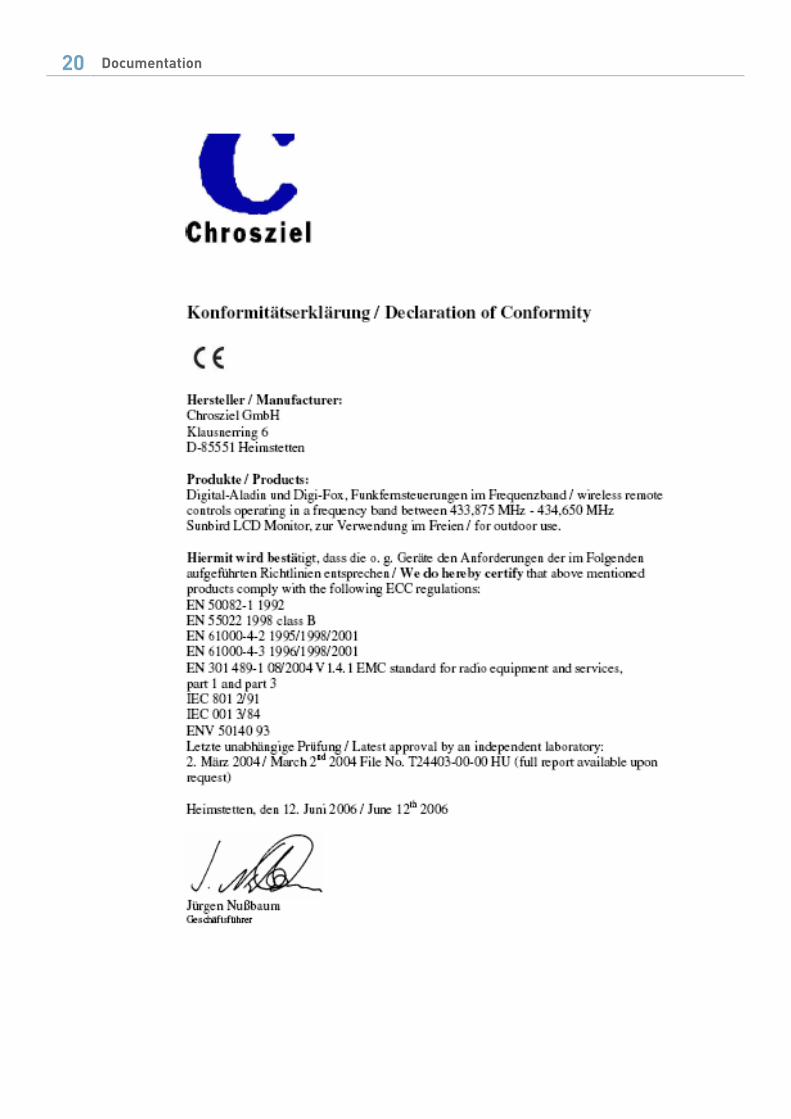
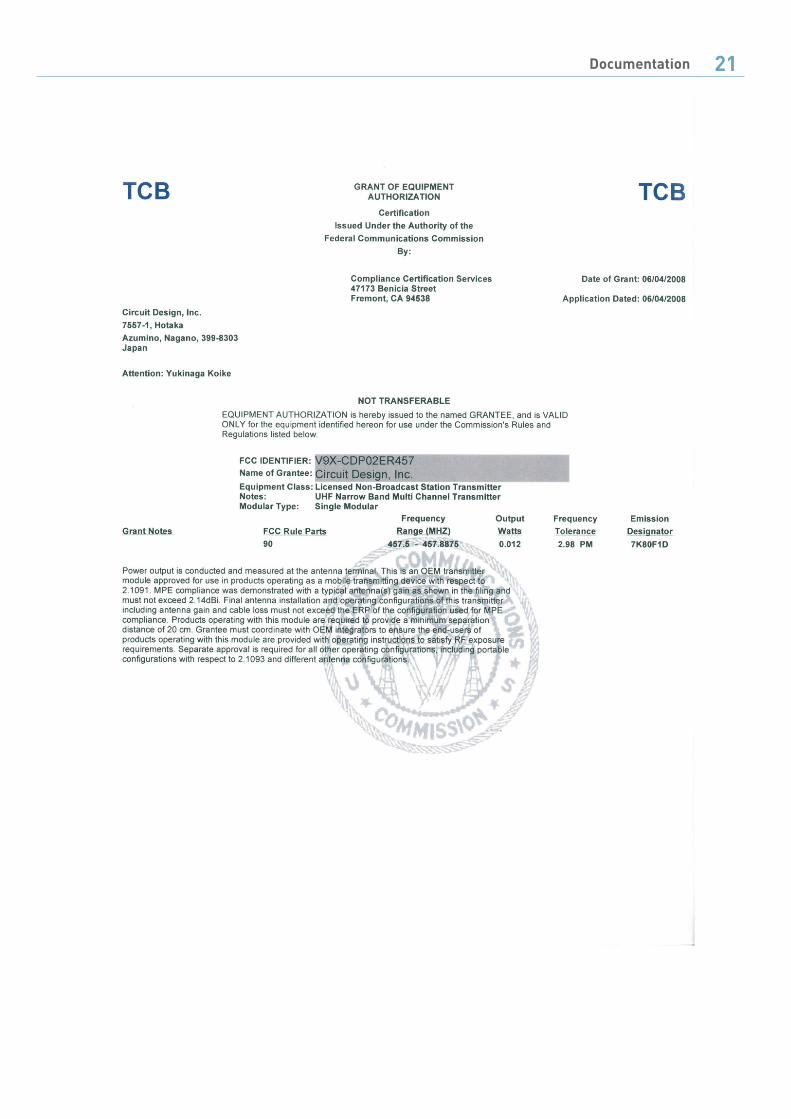
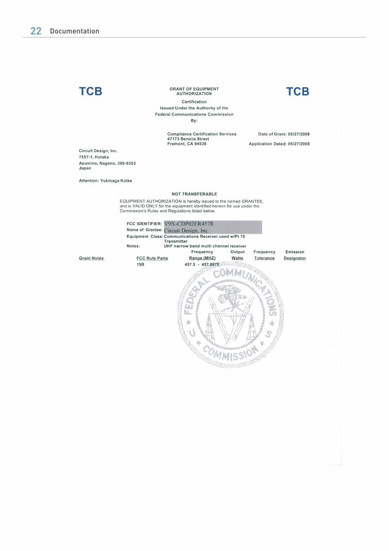
4 Declarations of conformity
20 Documentation
Documentation 21
22 Documentation


24 Documentation