diffraction-limited fundamental mode operation of core-pumped very-large-mode-area er fiber...
TRANSCRIPT

IEEE JOURNAL OF SELECTED TOPICS IN QUANTUM ELECTRONICS, VOL. 15, NO. 1, JANUARY/FEBRUARY 2009 3
Diffraction-Limited Fundamental Mode Operationof Core-Pumped Very-Large-Mode-Area
Er Fiber AmplifiersJayesh C. Jasapara, Matt J. Andrejco, Anthony DeSantolo, Andrew D. Yablon, Zoltan Varallyay,
Jeffrey W. Nicholson, Member, IEEE, John M. Fini, Member, IEEE, David J. DiGiovanni,Clifford Headley, Eric Monberg, and Frank V. DiMarcello
Abstract—Diffraction-limited fundamental mode amplificationis demonstrated in Er-doped fibers with mode areas ranging from900 to 1800 µm2 . The amplifiers are core-pumped with Ramanfiber lasers with both signal and pump selectively launched intothe fundamental mode. This scheme results in differential gainfor the fundamental mode and stabilizes it against mode mixingcaused by perturbations in the core. Gains that are greater than30 dB are demonstrated from a single stage without significantamplified spontaneous emission. The low nonlinearity of the largemode areas enables amplification to high peak powers withoutresorting to unconventional microstructured or higher order modefibers.
Index Terms—Core pumping, differential gain, Er fiber ampli-fier, large-mode-area fiber, picosecond pulse amplification, Ramanlaser.
I. INTRODUCTION
THE DISTRIBUTED gain geometry of fiber amplifiers, inwhich both signal and pump are guided and interact over
long lengths, overcomes several thermal and efficiency prob-lems associated with solid-state amplifiers. However, the limitedeffective area (Aeff ) of the guided mode imposes limitations dueto nonlinearities. Current research in fiber amplifiers has focusedon fiber designs that enable diffraction-limited operation withmode areas of multiple 1000 µm2 .
Increasing Aeff in a single-mode fiber by increasing core sizewhile reducing its numerical aperture to keep it single-moded isultimately limited by bend loss [1]. Microstructured fibers withdesigns in the so-called “endlessly single mode” regime encasedin a rigid glass rod have been used to minimize the bend loss—diffraction-limited amplifiers with Aeff exceeding 2000 µm2
having been demonstrated with this scheme [2]. However, theirgain length is limited by the rigid fiber geometry.
Manuscript received September 5, 2008; revised October 13, 2008 andNovember 4, 2008; accepted November 4, 2008. Current version publishedFebruary 4, 2009.
J. C. Jasapara, M. J. Andrejco, A. DeSantolo, A. D. Yablon, J. W. Nicholson,J. M. Fini, D. J. DiGiovanni, C. Headley, E. Monberg, and F. V. DiMarcelloare with OFS Laboratories, Somerset, NJ 08873 USA (e-mail: [email protected]; [email protected]; [email protected]; [email protected]; [email protected]; [email protected]; [email protected]; [email protected]; [email protected]; [email protected]).
Z. Varallyay is with Furukawa Electric Institute of Technology (FETI) Ltd.,Budapest H-1158, Hungary (e-mail: [email protected]).
Color versions of one or more of the figures in this paper are available onlineat http://ieeexplore.ieee.org.
Digital Object Identifier 10.1109/JSTQE.2008.2010262
Multimode fiber amplifiers can be operated in the funda-mental mode [3]. However, they are susceptible to microbend-induced coupling of the fundamental mode to higher ordermodes [4], [5]. The interference between the modes makes theoutput beam unstable and nondiffraction-limited [6], [7]. Dif-ferential loss or gain mechanisms between modes can be usedto stabilize the fundamental mode operation of the multimodeamplifier [4], [5]. Fundamental mode operation using bend-induced mode filtering [8] and fibers with index and dopantprofiles engineered for differential loss/gain [9]–[12] have beendemonstrated successfully. As an extreme example, microstruc-tured fiber amplifiers have recently been designed with largedifferential loss for higher order modes, which has alloweddiffraction-limited amplification with Aeff ∼ 1500 µm2 andstable fundamental mode propagation in undoped fibers withAeff ∼ 14 000 µm2 [13], [14].
Propagation and amplification in higher order modes of multi-mode fibers is also being explored to scale up the mode effectivearea [15].
All amplifier schemes described earlier employ the double-clad fiber geometry consisting of a doped central core, inwhich the signal propagates, surrounded by an undoped high-numerical-aperture region (called the inner cladding) into whichhundreds of watts of highly divergent (low brightness) pumplight from diodes can be coupled efficiently. The entire dopedregion is equally inverted across the core cross section, andtherefore, all core modes are supported. The cladding pumpscheme has the disadvantage that the pump absorption per unitlength is reduced by a factor proportional to the ratio of thecore to inner clad area. Therefore, higher concentrations ofcore dopants are required for efficient pump absorption overshort fiber lengths desirable to minimize nonlinear effects, am-plified spontaneous emission (ASE), and signal reabsorption.However, the dopant concentration is limited by effects such aspair-induced quenching (as with Er [16]) and photodarkening(as with Yb [17]).
Most research on large-mode-area fiber amplifiers has con-centrated on Yb-doped fibers operating at wavelengths in the1 µm region. However, several applications require operationat eye-safe wavelengths around 1.5 µm. Since Er concentra-tion in silica is limited by pair-induced quenching, double-cladEr–Yb-codoped fibers are typically used in this eye-safe re-gion [18]—the pump energy is absorbed by Yb and transferredto the Er. To increase the energy transfer efficiency, the fibers are
1077-260X/$25.00 © 2009 IEEE
4 IEEE JOURNAL OF SELECTED TOPICS IN QUANTUM ELECTRONICS, VOL. 15, NO. 1, JANUARY/FEBRUARY 2009
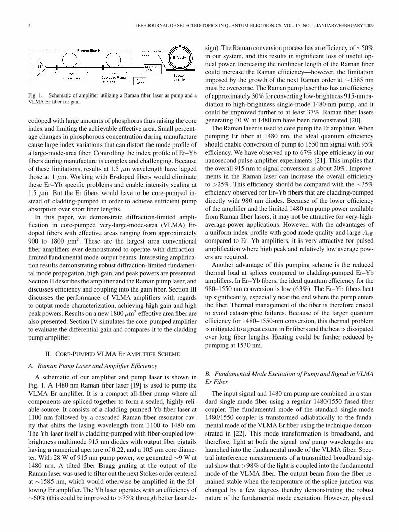
Fig. 1. Schematic of amplifier utilizing a Raman fiber laser as pump and aVLMA Er fiber for gain.
codoped with large amounts of phosphorus thus raising the coreindex and limiting the achievable effective area. Small percent-age changes in phosphorous concentration during manufacturecause large index variations that can distort the mode profile ofa large-mode-area fiber. Controlling the index profile of Er–Ybfibers during manufacture is complex and challenging. Becauseof these limitations, results at 1.5 µm wavelength have laggedthose at 1 µm. Working with Er-doped fibers would eliminatethese Er–Yb specific problems and enable intensity scaling at1.5 µm. But the Er fibers would have to be core-pumped in-stead of cladding-pumped in order to achieve sufficient pumpabsorption over short fiber lengths.
In this paper, we demonstrate diffraction-limited ampli-fication in core-pumped very-large-mode-area (VLMA) Er-doped fibers with effective areas ranging from approximately900 to 1800 µm2 . These are the largest area conventionalfiber amplifiers ever demonstrated to operate with diffraction-limited fundamental mode output beams. Interesting amplifica-tion results demonstrating robust diffraction-limited fundamen-tal mode propagation, high gain, and peak powers are presented.Section II describes the amplifier and the Raman pump laser, anddiscusses efficiency and coupling into the gain fiber. Section IIIdiscusses the performance of VLMA amplifiers with regardsto output mode characterization, achieving high gain and highpeak powers. Results on a new 1800 µm2 effective area fiber arealso presented. Section IV simulates the core-pumped amplifierto evaluate the differential gain and compares it to the claddingpump amplifier.
II. CORE-PUMPED VLMA Er AMPLIFIER SCHEME
A. Raman Pump Laser and Amplifier Efficiency
A schematic of our amplifier and pump laser is shown inFig. 1. A 1480 nm Raman fiber laser [19] is used to pump theVLMA Er amplifier. It is a compact all-fiber pump where allcomponents are spliced together to form a sealed, highly reli-able source. It consists of a cladding-pumped Yb fiber laser at1100 nm followed by a cascaded Raman fiber resonator cav-ity that shifts the lasing wavelength from 1100 to 1480 nm.The Yb laser itself is cladding-pumped with fiber-coupled low-brightness multimode 915 nm diodes with output fiber pigtailshaving a numerical aperture of 0.22, and a 105 µm core diame-ter. With 28 W of 915 nm pump power, we generated ∼9 W at1480 nm. A tilted fiber Bragg grating at the output of theRaman laser was used to filter out the next Stokes order centeredat ∼1585 nm, which would otherwise be amplified in the fol-lowing Er amplifier. The Yb laser operates with an efficiency of∼60% (this could be improved to >75% through better laser de-
sign). The Raman conversion process has an efficiency of∼50%in our system, and this results in significant loss of useful op-tical power. Increasing the nonlinear length of the Raman fibercould increase the Raman efficiency—however, the limitationimposed by the growth of the next Raman order at ∼1585 nmmust be overcome. The Raman pump laser thus has an efficiencyof approximately 30% for converting low-brightness 915-nm ra-diation to high-brightness single-mode 1480-nm pump, and itcould be improved further to at least 37%. Raman fiber lasersgenerating 40 W at 1480 nm have been demonstrated [20].
The Raman laser is used to core pump the Er amplifier. Whenpumping Er fiber at 1480 nm, the ideal quantum efficiencyshould enable conversion of pump to 1550 nm signal with 95%efficiency. We have observed up to 67% slope efficiency in ournanosecond pulse amplifier experiments [21]. This implies thatthe overall 915 nm to signal conversion is about 20%. Improve-ments in the Raman laser can increase the overall efficiencyto >25%. This efficiency should be compared with the ∼35%efficiency observed for Er–Yb fibers that are cladding-pumpeddirectly with 980 nm diodes. Because of the lower efficiencyof the amplifier and the limited 1480 nm pump power availablefrom Raman fiber lasers, it may not be attractive for very-high-average-power applications. However, with the advantages ofa uniform index profile with good mode quality and large Aeffcompared to Er–Yb amplifiers, it is very attractive for pulsedamplification where high peak and relatively low average pow-ers are required.
Another advantage of this pumping scheme is the reducedthermal load at splices compared to cladding-pumped Er–Ybamplifiers. In Er–Yb fibers, the ideal quantum efficiency for the980–1550 nm conversion is low (63%). The Er–Yb fibers heatup significantly, especially near the end where the pump entersthe fiber. Thermal management of the fiber is therefore crucialto avoid catastrophic failures. Because of the larger quantumefficiency for 1480–1550-nm conversion, this thermal problemis mitigated to a great extent in Er fibers and the heat is dissipatedover long fiber lengths. Heating could be further reduced bypumping at 1530 nm.
B. Fundamental Mode Excitation of Pump and Signal in VLMAEr Fiber
The input signal and 1480 nm pump are combined in a stan-dard single-mode fiber using a regular 1480/1550 fused fibercoupler. The fundamental mode of the standard single-mode1480/1550 coupler is transformed adiabatically to the funda-mental mode of the VLMA Er fiber using the technique demon-strated in [22]. This mode transformation is broadband, andtherefore, light at both the signal and pump wavelengths arelaunched into the fundamental mode of the VLMA fiber. Spec-tral interference measurements of a transmitted broadband sig-nal show that >98% of the light is coupled into the fundamentalmode of the VLMA fiber. The output beam from the fiber re-mained stable when the temperature of the splice junction waschanged by a few degrees thereby demonstrating the robustnature of the fundamental mode excitation. However, physical

JASAPARA et al.: DIFFRACTION-LIMITED FUNDAMENTAL MODE OPERATION OF CORE-PUMPED VLMA Er FIBER AMPLIFIERS 5
Fig. 2. (a) Change in core index due to bending the fiber. Solid line is the coreindex, dotted line is the mode effective index, and dashed line is the modifiedcore index due to bending. (b) Graph shows the change in effective area of thefundamental modes for the Aeff ∼ 1200 µm2 (solid line) and Aeff ∼ 1800 µm2
(dashed line) fibers as a function of bend radius.
stress on the splice resulted in coupling light to higher ordermodes.
The perfect overlap of the signal with the pump has severalpositive implications. First, the core pump absorption is high,and therefore, only short gain lengths are needed, which mini-mizes nonlinearities. Second, the Er concentration can be keptto a relatively low level at which efficiency degradation due topair-induced quenching is small [16]. Third, since the overlapof the higher order modes with the inverted ions is small, theASE in the higher order modes is not supported. This meansthat large gain can be extracted from a single stage before beinglimited by ASE. Fourth, the fundamental mode sees differentialgain (see simulations in Section IV) with respect to higher ordermodes, which stabilizes it against transfer of power to higherorder modes due to microbend-induced coupling [4], [5]. Notethat whereas the pump light also suffers similar coupling tohigher order modes, this small fraction of scattered pump en-ergy is not significant enough to alter the ion inversion profile.Fifth, since both pump and signal are in the fundamental coremode, they see the same bend-induced distortion (described inSection II-C next) that leaves the signal and gain overlap al-most unchanged on bending the fiber. This is an advantage overamplifier schemes where the dopant profile is engineered to pro-vide the differential gain. Our amplifier scheme thus facilitatesscaling up the fiber Aeff while maintaining robust fundamentalmode propagation and amplification.
C. Bend-Induced Mode Distortion
When mode areas exceed a few hundred square microns, thechange in index profile due to coiling the fiber [see Fig. 2(a)]has a significant impact on the mode shape. This can reduce itseffective area [23] thereby increasing nonlinear signal impair-ment [24], and impacting the gain overlap and mode compe-tition in an amplifier [25]. The core index is perturbed by thebend to an equivalent tilted index according to the well-knownconformal mapping in [26]. Mode distortion occurs if the per-turbation is large enough so that the equivalent index (dashedcurve) drops below the effective mode index (dotted line) in partof the core, as shown in Fig. 2(a). This part of the core (shaded)essentially acts as a cladding, excluding the mode and compress-
Fig. 3. Fundamental mode profiles calculated from tomographically measuredindex profiles of three different VLMA fibers.
ing it into the remainder of the core. The degree of distortioncan be directly related to the ratio ∆nbend/∆neff [27]. A full2-D finite-difference method was used to calculate the changein effective area with bend radius for two fibers used in stud-ies (presented in later sections) with ideal Aeff ∼ 1200 µm2 andAeff ∼ 1800 µm2 [see Fig. 2(b)]. They show that even large coildiameters around 40 cm result in significant distortion and areareduction. Keeping these results in mind, during experiments,the VLMA fibers were loosely coiled with diameters exceeding40 cm, with the last half meter (where the signal is most intense)held almost straight.
III. VLMA Er AMPLIFIER PERFORMANCE
This section provides details on the performance of theVLMA fibers and highlights some of the amplifier results ob-tained with them.
A. Characterization of Output Mode
In the past, fibers with Aeff ∼ 800 µm2 were considered to beat the edge of the limits of robust fundamental mode propaga-tion. Beyond this, the output mode was expected to be unstabledue to microbend-induced coupling between the fundamentaland higher order modes. We have studied and demonstratedrobust single-mode propagation and amplification in three dif-ferent Er fibers with effective areas of 875 µm2 , 1170 µm2 , and1760 µm2 . The fibers have a nominally step-index design. Thefundamental mode distribution of these fibers, calculated (usingthe beam propagation method) from their tomographically mea-sured index profiles, is shown in Fig. 3. These along with themeasured near-field images (see insets of Figs. 4 and 9) showthat the output beam is near-circular, which points to the highdegree of radial and azimuthal symmetry in the index of thefibers.
The VLMA output mode was characterized in detail by theso-called M 2- and S2 techniques. A detailed investigation ofthe Aeff = 1170 µm2 Er fiber is presented as a case in point.This fiber had a 54-µm-diameter step-index core and a 200 µmcladding diameter. A ∼2 m gain length, optimal for amplifyingpicosecond pulses (described in Section III-C), was used in these
6 IEEE JOURNAL OF SELECTED TOPICS IN QUANTUM ELECTRONICS, VOL. 15, NO. 1, JANUARY/FEBRUARY 2009
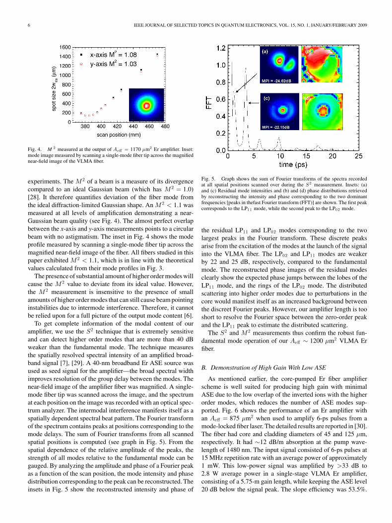
Fig. 4. M 2 measured at the output of Aeff = 1170 µm2 Er amplifier. Inset:mode image measured by scanning a single-mode fiber tip across the magnifiednear-field image of the VLMA fiber.
experiments. The M 2 of a beam is a measure of its divergencecompared to an ideal Gaussian beam (which has M 2 = 1.0)[28]. It therefore quantifies deviation of the fiber mode fromthe ideal diffraction-limited Gaussian shape. An M 2 < 1.1 wasmeasured at all levels of amplification demonstrating a near-Gaussian beam quality (see Fig. 4). The almost perfect overlapbetween the x-axis and y-axis measurements points to a circularbeam with no astigmatism. The inset in Fig. 4 shows the modeprofile measured by scanning a single-mode fiber tip across themagnified near-field image of the fiber. All fibers studied in thispaper exhibited M 2 < 1.1, which is in line with the theoreticalvalues calculated from their mode profiles in Fig. 3.
The presence of substantial amount of higher order modes willcause the M 2 value to deviate from its ideal value. However,the M 2 measurement is insensitive to the presence of smallamounts of higher order modes that can still cause beam pointinginstabilities due to intermode interference. Therefore, it cannotbe relied upon for a full picture of the output mode content [6].
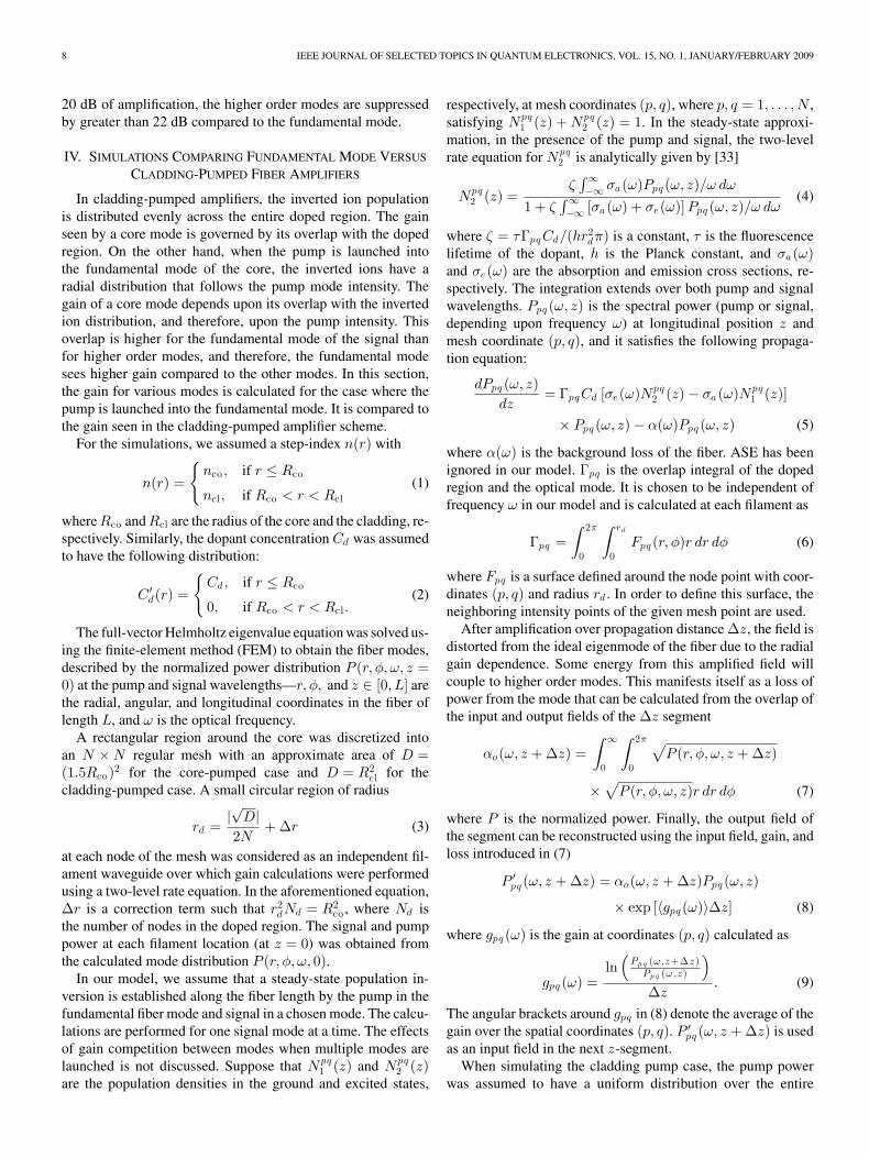
To get complete information of the modal content of ouramplifier, we use the S2 technique that is extremely sensitiveand can detect higher order modes that are more than 40 dBweaker than the fundamental mode. The technique measuresthe spatially resolved spectral intensity of an amplified broad-band signal [7], [29]. A 40-nm broadband Er ASE source wasused as seed signal for the amplifier—the broad spectral widthimproves resolution of the group delay between the modes. Thenear-field image of the amplifier fiber was magnified. A single-mode fiber tip was scanned across the image, and the spectrumat each position on the image was recorded with an optical spec-trum analyzer. The intermodal interference manifests itself as aspatially dependent spectral beat pattern. The Fourier transformof the spectrum contains peaks at positions corresponding to themode delays. The sum of Fourier transforms from all scannedspatial positions is computed (see graph in Fig. 5). From thespatial dependence of the relative amplitude of the peaks, thestrength of all modes relative to the fundamental mode can begauged. By analyzing the amplitude and phase of a Fourier peakas a function of the scan position, the mode intensity and phasedistribution corresponding to the peak can be reconstructed. Theinsets in Fig. 5 show the reconstructed intensity and phase of
Fig. 5. Graph shows the sum of Fourier transforms of the spectra recordedat all spatial positions scanned over during the S2 measurement. Insets: (a)and (c) Residual mode intensities and (b) and (d) phase distributions retrievedby reconstructing the intensity and phase corresponding to the two dominantfrequencies [peaks in thefast Fourier transform (FFT)] are shown. The first peakcorresponds to the LP11 mode, while the second peak to the LP02 mode.
the residual LP11 and LP02 modes corresponding to the twolargest peaks in the Fourier transform. These discrete peaksarise from the excitation of the modes at the launch of the signalinto the VLMA fiber. The LP02 and LP11 modes are weakerby 22 and 25 dB, respectively, compared to the fundamentalmode. The reconstructed phase images of the residual modesclearly show the expected phase jumps between the lobes of theLP11 mode, and the rings of the LP02 mode. The distributedscattering into higher order modes due to perturbations in thecore would manifest itself as an increased background betweenthe discreet Fourier peaks. However, our amplifier length is tooshort to resolve the Fourier space between the zero-order peakand the LP11 peak to estimate the distributed scattering.
The S2 and M 2 measurements thus confirm the robust fun-damental mode operation of our Aeff ∼ 1200 µm2 VLMA Erfiber.
B. Demonstration of High Gain With Low ASE
As mentioned earlier, the core-pumped Er fiber amplifierscheme is well suited for producing high gain with minimalASE due to the low overlap of the inverted ions with the higherorder modes, which reduces the number of ASE modes sup-ported. Fig. 6 shows the performance of an Er amplifier withan Aeff = 875 µm2 when used to amplify 6-ps pulses from amode-locked fiber laser. The detailed results are reported in [30].The fiber had core and cladding diameters of 45 and 125 µm,respectively. It had ∼12 dB/m absorption at the pump wave-length of 1480 nm. The input signal consisted of 6-ps pulses at15 MHz repetition rate with an average power of approximately1 mW. This low-power signal was amplified by >33 dB to2.8 W average power in a single-stage VLMA Er amplifier,consisting of a 5.75-m gain length, while keeping the ASE level20 dB below the signal peak. The slope efficiency was 53.5%.

JASAPARA et al.: DIFFRACTION-LIMITED FUNDAMENTAL MODE OPERATION OF CORE-PUMPED VLMA Er FIBER AMPLIFIERS 7
Fig. 6. (a) Average signal output power versus 1480 nm pump power.(b) Spectrum measured at highest gain with 0.1 nm resolution.
Fig. 7. (a) Average signal output power and pulse energy versus 1480 nmpump power. (b) Autocorrelation measured at the minimum and maximumpulse energies Ep . Inset: spectrum measured at minimum and maximum pulseenergies.
The output beam was diffraction-limited with an M 2 < 1.1 atall power levels. Achieving the same high level of amplificationin a cladding-pumped double-clad Er–Yb fiber would typicallyrequire a couple of amplifier stages with intermediate filtersand isolators. Thus, the amplifier scheme greatly simplifies theoverall system architecture.
C. Amplification to High Peak Powers
The large effective area of the Er fibers have been used suc-cessfully for direct amplification of picosecond pulses to recordpulse energy prior to the onset of pulse breakup due to nonlin-earities [31], [32]. In [32], the Er fiber with Aeff ∼ 1200 µm2
(mode properties described in Section III-A) was used to amplify100-pJ energy 1-ps pulses from a mode-locked fiber oscillator.The fiber had core and cladding diameters of 54 and 200 µm, re-spectively. It had ∼27 dB/m absorption at the pump wavelengthof 1480 nm. Fig. 7(a) shows the output power and pulse energyas a function of 1480 nm pump power. The intensity autocor-relations recorded at the minimum and maximum pulse energyare shown in Fig. 7(b), and the inset shows the correspondingspectra. Pulse energies up to 67 nJ were obtained in a single-stage amplifier before soliton-effect-compression-induced pulsebreakup. A deconvolution factor of 1.62 was calculated from thepulse spectrum (assuming a uniform spectral phase), to relatethe autocorrelation full-width at half-maximum (FWHM) to thepulse FWHM. The pulse duration at maximum pulse energywas estimated to be ∼526 fs. The autocorrelation of a 526-fs-duration sech pulse is broader at the peak and narrower at thebase when compared to our measured trace. Therefore, whereasour estimate of the pulse duration is not exact, we believe that it
Fig. 8. (a) Average signal output power versus 1480 nm pump power.(b) Spectrum measured at maximum power with 0.05 nm resolution.
Fig. 9. M 2 measured for the Aeff = 1760 µm2 Er fiber. Inset: output beamprofile measured by scanning a single-mode fiber across the magnified near-fieldimage of the mode.
is a reasonable compromise. The peak power was estimated at127 kW (defined as pulse energy divided by pulse FWHM sincethe exact pulse shape is unknown). This is a record pulse peakpower and energy at 1.5 µm wavelength for a conventional fiberamplifier operating in the fundamental mode, and it is enabledby the large mode area of the fiber.
D. Continuous-Wave (CW) Amplification in Aeff = 1760 µm2
Fiber
We recently fabricated an Er fiber with an Aeff = 1760 µm2
with a core (clad) diameter of 70 µm (200 µm). It had ∼7 dB/mabsorption at the pump wavelength of 1480 nm. Results oncharacterizing the fiber and its performance in a CW amplifierare described. The fiber was used to amplify a 17 mW CWsignal at 1548 nm generated by a laser diode. It was coiled witha bend radius of ∼25 cm. The amplification results are shownin Fig. 8. The signal was amplified by greater than 22 dB whilekeeping the ASE >50 dB below the signal. A slope efficiencyof 56% was observed for an optimized gain length of ∼7.4 m.
An M 2 < 1.1 was measured for all power levels (see Fig. 9).The amplified output beam shown in the inset was measuredby scanning a single-mode fiber across the magnified near-fieldimage of the mode. As with other VLMA fibers, the outputbeam of an undisturbed fiber remained uniform and steadyat all power levels—applying pressure on the fiber distortedthe mode. S2 measurements show that even after greater than
8 IEEE JOURNAL OF SELECTED TOPICS IN QUANTUM ELECTRONICS, VOL. 15, NO. 1, JANUARY/FEBRUARY 2009
20 dB of amplification, the higher order modes are suppressedby greater than 22 dB compared to the fundamental mode.
IV. SIMULATIONS COMPARING FUNDAMENTAL MODE VERSUS
CLADDING-PUMPED FIBER AMPLIFIERS
In cladding-pumped amplifiers, the inverted ion populationis distributed evenly across the entire doped region. The gainseen by a core mode is governed by its overlap with the dopedregion. On the other hand, when the pump is launched intothe fundamental mode of the core, the inverted ions have aradial distribution that follows the pump mode intensity. Thegain of a core mode depends upon its overlap with the invertedion distribution, and therefore, upon the pump intensity. Thisoverlap is higher for the fundamental mode of the signal thanfor higher order modes, and therefore, the fundamental modesees higher gain compared to the other modes. In this section,the gain for various modes is calculated for the case where thepump is launched into the fundamental mode. It is compared tothe gain seen in the cladding-pumped amplifier scheme.
For the simulations, we assumed a step-index n(r) with
n(r) =
{nco , if r ≤ Rco
ncl, if Rco < r < Rcl(1)
where Rco and Rcl are the radius of the core and the cladding, re-spectively. Similarly, the dopant concentration Cd was assumedto have the following distribution:
C ′d(r) =
{Cd, if r ≤ Rco
0, if Rco < r < Rcl.(2)
The full-vector Helmholtz eigenvalue equation was solved us-ing the finite-element method (FEM) to obtain the fiber modes,described by the normalized power distribution P (r, φ, ω, z =0) at the pump and signal wavelengths—r, φ, and z ∈ [0, L] arethe radial, angular, and longitudinal coordinates in the fiber oflength L, and ω is the optical frequency.
A rectangular region around the core was discretized intoan N × N regular mesh with an approximate area of D =(1.5Rco)2 for the core-pumped case and D = R2
cl for thecladding-pumped case. A small circular region of radius
rd =|√
D|2N
+ ∆r (3)
at each node of the mesh was considered as an independent fil-ament waveguide over which gain calculations were performedusing a two-level rate equation. In the aforementioned equation,∆r is a correction term such that r2
dNd = R2co , where Nd is
the number of nodes in the doped region. The signal and pumppower at each filament location (at z = 0) was obtained fromthe calculated mode distribution P (r, φ, ω, 0).
In our model, we assume that a steady-state population in-version is established along the fiber length by the pump in thefundamental fiber mode and signal in a chosen mode. The calcu-lations are performed for one signal mode at a time. The effectsof gain competition between modes when multiple modes arelaunched is not discussed. Suppose that Npq
1 (z) and Npq2 (z)
are the population densities in the ground and excited states,
respectively, at mesh coordinates (p, q), where p, q = 1, . . . , N ,satisfying Npq
1 (z) + Npq2 (z) = 1. In the steady-state approxi-
mation, in the presence of the pump and signal, the two-levelrate equation for Npq
2 is analytically given by [33]
Npq2 (z) =
ζ∫ ∞−∞ σa(ω)Ppq (ω, z)/ω dω
1 + ζ∫ ∞−∞ [σa(ω) + σe(ω)] Ppq (ω, z)/ω dω
(4)
where ζ = τΓpqCd/(hr2dπ) is a constant, τ is the fluorescence
lifetime of the dopant, h is the Planck constant, and σa(ω)and σe(ω) are the absorption and emission cross sections, re-spectively. The integration extends over both pump and signalwavelengths. Ppq (ω, z) is the spectral power (pump or signal,depending upon frequency ω) at longitudinal position z andmesh coordinate (p, q), and it satisfies the following propaga-tion equation:
dPpq (ω, z)dz
= ΓpqCd [σe(ω)Npq2 (z) − σa(ω)Npq
1 (z)]
× Ppq (ω, z) − α(ω)Ppq (ω, z) (5)
where α(ω) is the background loss of the fiber. ASE has beenignored in our model. Γpq is the overlap integral of the dopedregion and the optical mode. It is chosen to be independent offrequency ω in our model and is calculated at each filament as
Γpq =∫ 2π
0
∫ rd
0Fpq (r, φ)r dr dφ (6)
where Fpq is a surface defined around the node point with coor-dinates (p, q) and radius rd . In order to define this surface, theneighboring intensity points of the given mesh point are used.
After amplification over propagation distance ∆z, the field isdistorted from the ideal eigenmode of the fiber due to the radialgain dependence. Some energy from this amplified field willcouple to higher order modes. This manifests itself as a loss ofpower from the mode that can be calculated from the overlap ofthe input and output fields of the ∆z segment
αo(ω, z + ∆z) =∫ ∞
0
∫ 2π
0
√P (r, φ, ω, z + ∆z)
×√
P (r, φ, ω, z)r dr dφ (7)
where P is the normalized power. Finally, the output field ofthe segment can be reconstructed using the input field, gain, andloss introduced in (7)
P ′pq (ω, z + ∆z) = αo(ω, z + ∆z)Ppq (ω, z)
× exp [〈gpq (ω)〉∆z] (8)
where gpq (ω) is the gain at coordinates (p, q) calculated as
gpq (ω) =ln
(Pp q (ω,z+∆z )
Pp q (ω,z )
)∆z
. (9)
The angular brackets around gpq in (8) denote the average of thegain over the spatial coordinates (p, q). P ′
pq (ω, z + ∆z) is usedas an input field in the next z-segment.
When simulating the cladding pump case, the pump powerwas assumed to have a uniform distribution over the entire
JASAPARA et al.: DIFFRACTION-LIMITED FUNDAMENTAL MODE OPERATION OF CORE-PUMPED VLMA Er FIBER AMPLIFIERS 9
TABLE IPARAMETERS USED FOR MODELING THE AMPLIFICATION OF DIFFERENT
MODES WITH CW INPUT
Fig. 10. Average mode gain per unit length as a function of the fundamentalmode area. (a) Pump in the fundamental core mode. (b) Cladding pumpedcase. Note: the fiber with 500 µm2 mode area does not support LP03 mode at1550 nm.
200 µm inner cladding diameter. The same formalism as be-fore was used for the gain calculations.
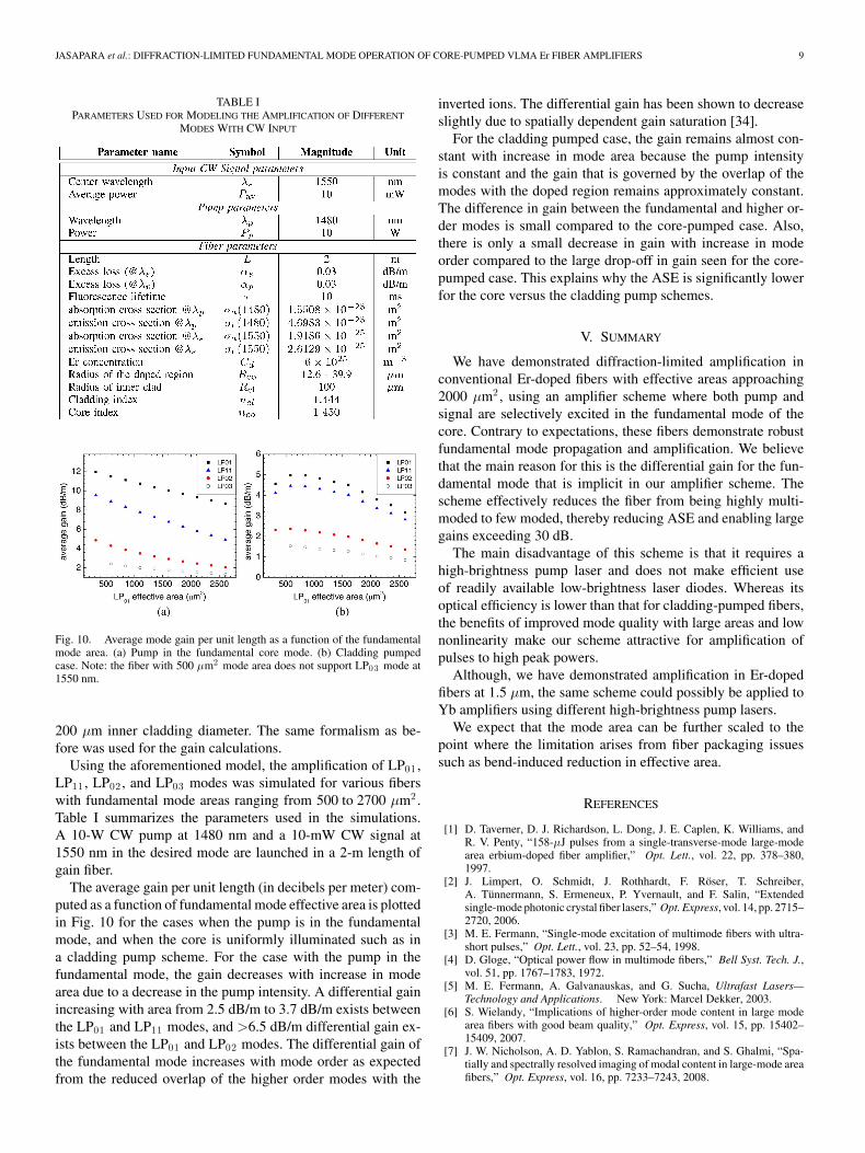
Using the aforementioned model, the amplification of LP01 ,LP11 , LP02 , and LP03 modes was simulated for various fiberswith fundamental mode areas ranging from 500 to 2700 µm2 .Table I summarizes the parameters used in the simulations.A 10-W CW pump at 1480 nm and a 10-mW CW signal at1550 nm in the desired mode are launched in a 2-m length ofgain fiber.
The average gain per unit length (in decibels per meter) com-puted as a function of fundamental mode effective area is plottedin Fig. 10 for the cases when the pump is in the fundamentalmode, and when the core is uniformly illuminated such as ina cladding pump scheme. For the case with the pump in thefundamental mode, the gain decreases with increase in modearea due to a decrease in the pump intensity. A differential gainincreasing with area from 2.5 dB/m to 3.7 dB/m exists betweenthe LP01 and LP11 modes, and >6.5 dB/m differential gain ex-ists between the LP01 and LP02 modes. The differential gain ofthe fundamental mode increases with mode order as expectedfrom the reduced overlap of the higher order modes with the
inverted ions. The differential gain has been shown to decreaseslightly due to spatially dependent gain saturation [34].
For the cladding pumped case, the gain remains almost con-stant with increase in mode area because the pump intensityis constant and the gain that is governed by the overlap of themodes with the doped region remains approximately constant.The difference in gain between the fundamental and higher or-der modes is small compared to the core-pumped case. Also,there is only a small decrease in gain with increase in modeorder compared to the large drop-off in gain seen for the core-pumped case. This explains why the ASE is significantly lowerfor the core versus the cladding pump schemes.
V. SUMMARY
We have demonstrated diffraction-limited amplification inconventional Er-doped fibers with effective areas approaching2000 µm2 , using an amplifier scheme where both pump andsignal are selectively excited in the fundamental mode of thecore. Contrary to expectations, these fibers demonstrate robustfundamental mode propagation and amplification. We believethat the main reason for this is the differential gain for the fun-damental mode that is implicit in our amplifier scheme. Thescheme effectively reduces the fiber from being highly multi-moded to few moded, thereby reducing ASE and enabling largegains exceeding 30 dB.
The main disadvantage of this scheme is that it requires ahigh-brightness pump laser and does not make efficient useof readily available low-brightness laser diodes. Whereas itsoptical efficiency is lower than that for cladding-pumped fibers,the benefits of improved mode quality with large areas and lownonlinearity make our scheme attractive for amplification ofpulses to high peak powers.
Although, we have demonstrated amplification in Er-dopedfibers at 1.5 µm, the same scheme could possibly be applied toYb amplifiers using different high-brightness pump lasers.
We expect that the mode area can be further scaled to thepoint where the limitation arises from fiber packaging issuessuch as bend-induced reduction in effective area.
REFERENCES
[1] D. Taverner, D. J. Richardson, L. Dong, J. E. Caplen, K. Williams, andR. V. Penty, “158-µJ pulses from a single-transverse-mode large-modearea erbium-doped fiber amplifier,” Opt. Lett., vol. 22, pp. 378–380,1997.
[2] J. Limpert, O. Schmidt, J. Rothhardt, F. Roser, T. Schreiber,A. Tunnermann, S. Ermeneux, P. Yvernault, and F. Salin, “Extendedsingle-mode photonic crystal fiber lasers,” Opt. Express, vol. 14, pp. 2715–2720, 2006.
[3] M. E. Fermann, “Single-mode excitation of multimode fibers with ultra-short pulses,” Opt. Lett., vol. 23, pp. 52–54, 1998.
[4] D. Gloge, “Optical power flow in multimode fibers,” Bell Syst. Tech. J.,vol. 51, pp. 1767–1783, 1972.
[5] M. E. Fermann, A. Galvanauskas, and G. Sucha, Ultrafast Lasers—Technology and Applications. New York: Marcel Dekker, 2003.
[6] S. Wielandy, “Implications of higher-order mode content in large modearea fibers with good beam quality,” Opt. Express, vol. 15, pp. 15402–15409, 2007.
[7] J. W. Nicholson, A. D. Yablon, S. Ramachandran, and S. Ghalmi, “Spa-tially and spectrally resolved imaging of modal content in large-mode areafibers,” Opt. Express, vol. 16, pp. 7233–7243, 2008.

10 IEEE JOURNAL OF SELECTED TOPICS IN QUANTUM ELECTRONICS, VOL. 15, NO. 1, JANUARY/FEBRUARY 2009
[8] J. P. Koplow, D. A. V. Kliner, and L. Goldberg, “Single-mode operationof a coiled multimode fiber amplifier,” Opt. Lett., vol. 25, pp. 442–444,2000.
[9] J. Nilsson, R. Paschotta, J. E. Caplen, and D. C. Hanna, “Yb+3 -ring-dopedfiber for high-energy pulse amplification,” Opt. Lett., vol. 22, pp. 1092–1094, 1997.
[10] H. L. Offerhaus, N. G. Broderick, D. J. Richardson, R. Sammut, J. Caplen,and L. Dong, “High-energy single-transverse-mode q-switched fiber laserbased on a multimode large-mode area erbium-doped fiber,” Opt. Lett.,vol. 23, pp. 1683–1685, 1998.
[11] J. Oh, C. Headley, M. J. Andrejco, A. D. Yablon, and D. J. DiGiovanni,“Increased pulsed amplifier efficiency by manipulating the fiber dopantdistribution,” presented at the Conf. Lasers Electro-Opt./Quantum Elec-tron. Laser Sci. Conf. Photon. Appl. Syst. Technol., Tech. Dig. (CD)[Washington, DC: Optical Society of America], 2006, Paper CTuQ3.
[12] J. M. Sousa and O. G. Okhotnikov, “Multimode Er-doped fiber for single-transverse-mode amplification,” Appl. Phys. Lett., vol. 74, pp. 1528–1530,1999.
[13] L. Dong, X. Peng, and J. Li, “Leakage channel optical fibers with largeeffective area,” J. Opt. Soc. Amer. B, Opt. Phys., vol. 24, pp. 1689–1697,2007.
[14] L. Dong, J. Li, H. McKay, A. Marcinkevicius, B. Thomas, M. Moore,L. Fu, and M. Fermann, “Robust and practical optical fibers for singlemode operation with core diameters up to 170 µm,” presented at the Conf.Lasers Electro-Opt., San Jose, 2008 [Washington, DC: Optical Society ofAmerica], Postdeadline Paper.
[15] S. Ramachandran, J. W. Nicholson, S. Ghalmi, M. F. Yan, P. Wisk,E. Monberg, and F. V. Dimarcello, “Light propagation with ultralargemodal areas in optical fibers,” Opt. Lett., vol. 31, pp. 1797–1799,2006.
[16] E. Delevaque, T. Georges, M. Monerie, P. Lamouler, and J. F. Bayon,“Modeling of pair-induced quenching in erbium-doped silicate fibers,”Photon. Technol. Lett., vol. 5, pp. 73–75, 1993.
[17] R. Paschotta, J. Nilsson, P. R. Barber, J. E. Caplen, A. C. Tropper, andD. C. Hanna, “Lifetime quenching in Yb-doped fibers,” Opt. Commun.,vol. 136, pp. 375–378, 1997.
[18] A. Galvanauskas, “Mode scalable fiber-based chirped pulse amplificationsystems,” IEEE J. Sel. Topics Quantum Electron., vol. 7, no. 4, pp. 504–517, Jul./Aug. 2001.
[19] C. Headley, “Cascaded Raman resonators,” in Raman Amplification inFiber Optical Communication Systems, Amsterdam, The Netherlands,Elsevier, 2006, pp. 303–374
[20] Y. Emori, K. Tanaka, C. Headley, and A. Fujisaki, “High-power cascadedRaman fiber laser with 41-W output power at 1480-nm band,” presented atthe Conf. Lasers Electro-Opt., 2007, Tech. Dig. [Washington, DC: OpticalSociety of America], Paper CFI2.
[21] J. Jasapara, M. J. Andrejco, A. D. Yablon, C. Headley, and D. DiGiovanni,“Core pumped erbium fiber nanosecond pulse amplifier generating 360kW peak power with M 2 < 1.1 at 1545 nm wavelength,” presented atthe Adv. Solid State Photon. Conf. [Washington, DC: Optical Society ofAmerica], 2007, Paper WE1.
[22] Cladding pumped optical fiber gain devices, by D. J. DiGiovanni andA. D. Yablon. (2005, Nov. 29). U.S. Patent 6 970 624 [Online]. Available:http://patft.uspto.gov
[23] J. M. Fini, “Bend-resistant design of conventional and microstructurefibers with very large mode area,” Opt. Express, vol. 14, pp. 69–81, 2006.
[24] J. W. Nicholson, J. M. Fini, A. D. Yablon, P. S. Westbrook, K. Feder, andC. Headley, “Demonstration of bend-induced nonlinearities in large-modearea fibers,” Opt. Lett., vol. 32, pp. 2562–2564, 2007.
[25] J. M. Fini, “Design of large-mode area amplifier fibers resistant to bend-induced distortion,” J. Opt. Soc. Amer. B, Opt. Phys., vol. 24, pp. 1669–1676, 2007.
[26] D. Marcuse, “Influence of curvature on the losses of doubly clad fibers,”Appl. Opt., vol. 21, pp. 4208–4213, 1982.
[27] J. M. Fini, “Intuitive modeling of bend distortion in large-mode areafibers,” Opt. Lett., vol. 32, pp. 1632–1634, 2007.
[28] P. Belanger, “Beam quality factor of the LP01 mode of the step-indexfiber,” Opt. Eng., vol. 32, pp. 2107–2109, 1993.
[29] J. W. Nicholson, A. D. Yablon, J. M. Fini, and M. D. Mermelstein, “Mea-suring the modal content of large-mode area fibers,” J. Sel. Topics Quan-tum Electron., vol. 15, no. 1, pp. xxx–xxx, Jan./Feb. 2009.
[30] J. Jasapara, M. J. Andrejco, A. D. Yablon, J. W. Nicholson, C. Headley,and D. DiGiovanni, “Picosecond pulse amplification in a core pumpedlarge-mode area erbium fiber,” Opt. Lett., vol. 32, pp. 2429–2431,2007.
[31] J. C. Jasapara, M. J. Andrejco, J. W. Nicholson, A. D. Yablon, andZ. Varallyay, “Simultaneous direct amplification and compression of pi-cosecond pulses to 65-kW peak power without pulse break-up in erbiumfiber,” Opt. Express, vol. 15, pp. 17494–17501, 2007.
[32] J. C. Jasapara, A. DeSantolo, J. W. Nicholson, A. D. Yablon, andZ. Varallyay, “Diffraction limited amplification of picosecond pulses in1170 µm2 effective area erbium fiber,” Opt. Express, vol. 16, pp. 18869–18874, 2008.
[33] E. Desurvire, Erbium-Doped Fiber Amplifiers—Principles and Applica-tions. New York: Wiley, 1994. ch. 1.
[34] Z. Jiang and J. R. Marciante, “Impact of transverse spatial-hole burningon beam quality in large-mode area Yb-doped fibers,” J. Opt. Soc. Amer.B. Opt. Phys., vol. 25, pp. 247–254, 2008.
Jayesh C. Jasapara received the B.Tech. degree inengineering physics from the Indian Institute of Tech-nology, Bombay, India, in 1995, and the Ph.D. de-gree in optical sciences from the University of NewMexico, Albuquerque.
Since 2001, he has been a Member of TechnicalStaff with OFS Laboratories, Somerset, NJ (formerlythe Optical Fiber Research Department of Bell Lab-oratories, Murray Hill, NJ). His current research in-terests include fiber lasers and amplifiers.
Matt J. Andrejco was engaged in optical fiber processing research and devel-opment activities with Western Electric Engineering Research Center (ERC),Bellcore, AT&T Bell Laboratories, and OFS Laboratories from 1970 to 2007.He retired in 2007 but remains active at OFS Laboratories with particular regardto rare-earth doped fibers for high-power applications.
Anthony DeSantolo received the B.S. degree in chemistry from the State Uni-versity of New York (SUNY), Binghamton, in 1978, and the M.S. degree inchemistry from Rutgers University, New Brunswick, in 1989.
From 1980 to 1986, he was with Exxon Research and Engineering Company,where he used laser-induced desorption to probe chemical reactions on metalsurfaces. From 1986 to 2001, he was with AT&T Bell Laboratories, where hewas engaged in the study of physics and chemistry of semiconductor clusters.Since 2002, he has been with OFS Laboratories, Somerset, NJ, where he isengaged primarily in making rare earth fibers.
Andrew D. Yablon was born in New York, NY, in1970. He received the S.B., S.M., and Ph.D. degreesfrom Massachusetts Institute of Technology (MIT),Cambridge, in 1992, 1993, and 1997, respectively, allin mechanical engineering.
From 1998 to 2000, he was a Senior Research Sci-entist at Vytran Corporation, Morganville, NJ, wherehe was engaged in developing novel fiber process-ing and fusion splicing technologies. Since 2000, hehas been a Member of Technical Staff at OFS Lab-oratories, Somerset, NJ (formerly the Optical Fiber
Research Department of Bell Laboratories, Lucent Technologies). He has au-thored or coauthored more than 50 peer-reviewed publications. He is a holder of11 U.S. patents. He recently wrote a monograph on optical fiber fusion splicing.His current research interests include optical fiber interconnection technologies,fusion splicing, fiber mechanical properties, and fiber measurements.
Dr. Yablon is a member of the Optical Society of America (OSA). Heis currently on the Optical Fiber Communication Conference and ExpositionCommittee and the National Fiber Optic Engineers Conference (OFC/NFOEC)Fibers and Propagation Effects Technical Program Committee.

JASAPARA et al.: DIFFRACTION-LIMITED FUNDAMENTAL MODE OPERATION OF CORE-PUMPED VLMA Er FIBER AMPLIFIERS 11
Zoltan Varallyay was born in Budapest, Hungary,on December 8, 1974. He received the M.Sc. degreefrom the University of Szeged, Szeged, Hungary, in2001, and the Ph.D. degree from the Budapest Uni-versity of Technology and Economics, Budapest, in2007, both in physics.
Since 2000, he has been with Furukawa Elec-tric Institute of Technology (FETI) Ltd., Budapest.His current research interests include optical-fiber-related projects including nonlinear, ultrashort pulsetransmission and compression in conventional and
microstructured fibers, amplification in doped and Raman fiber amplifiers, po-larization mode dispersion in mechanically stressed optical fibers, and the designof photonic bandgap fibers with special dispersive properties.
Jeffrey W. Nicholson (M’03) was born in Louisville,KY, in 1969. He received the B.S. degree in physicsfrom the University of Houston, Houston, TX, in1991, and the Ph.D. degree in optical sciences fromthe University of New Mexico, Albuquerque, in 1997.
He was a Postdoctoral Researcher at Los AlamosNational Laboratory in the area of short pulse prop-agation and at the Directed Energy Solutions in thearea of high power gas lasers. Since 2001, he has beena Member of Technical Staff with OFS Laboratories,Somerset, NJ (formerly the Optical Fiber Research
Department of Bell Laboratories, Murray Hill, NJ). His current research inter-ests include fiber lasers and amplifiers, ultrashort pulses, and nonlinear propa-gation effects in fibers.
Dr. Nicholson is a member of the Optical Society of America (OSA) and theIEEE Lasers and Electro-Optics Society (IEEE/LEOS).
John M. Fini (M’05) was born in New York, NY,in 1974. He received the B.S., M.Eng., and Ph.D.degrees from the Department of Electrical Engineer-ing, Massachusetts Institute of Technology (MIT),Cambridge, in 1997 and 2001, respectively.
His master’s research dealt with signal process-ing and 3-D imaging at MIT Lincoln Laboratory. Hisdoctoral research at the MIT Research Laboratoryof Electronics under Prof. H. Haus and P. Hagel-stein focused on the quantum theory of optical soli-tons as well as measurement and compensation of
polarization-mode dispersion in communications. He was with Corlux Corpo-ration. He is currently with OFS Laboratories, Somerset, NJ, where he is engagedin modeling and simulation of microstructure optical fibers and nonlinear opticaldevices. He has developed several numerical codes in-house to complement andimprove intuitive design approaches. His resonant mode suppression approachhas addressed several fiber applications, including next generation low-bend-loss fibers for fiber to the home. In fiber amplifiers and lasers, he has illustratedthat bend distortion limits traditional area-scaling approaches, and suggestednovel strategies for getting around this limitation.
Dr. Fini is a member of the Optical Society of America (OSA) and the IEEELasers and Electro-Optics Society (IEEE/LEOS).
David J. DiGiovanni received the Ph.D. degree in mechanical engineering fromBrown University, Providence, RI.
He is currently with the OFS Laboratories, Somerset, NJ. He has authoredmany technical publications, including chapters on fiber design and fabricationin several books. He holds more than 50 patents. His current research interestsinclude various phenomena related to optical fiber fabrication and applications,making notable contributions to erbium-doped optical fiber for amplifiers, high-power amplifiers and lasers, and Raman amplification and optical components.
Dr. DiGiovanni is a Fellow of the Optical Society of America (OSA). From2001 to 2006, he was an Associate Editor of Photonics Technology Letters.
Clifford Headley received the B.S. and M.S degreesin electrical engineering from the University of Texas,Arlington, in 1986 and 1988, respectively, and thePh.D. degree in optics from the Institute of Optics,University of Rochester, Rochester, NY, in 1995.
In 1995, he joined the Bell Laboratories. He is cur-rently a Technical Manager of the Laser Amplifiersand Nonlinear Devices Group, OFS Fitel Laborato-ries, Somerset, NJ. He has authored or coauthoredmore than 60 journals and conference articles, andtwo book chapters. He is a Co-Editor of a book on
Raman Amplification. He is a holder of seven patents. He has given severalinvited talks at both national and international conferences. His current researchinterests include high power fiber lasers and amplifiers and nonlinear optics.
Eric Monberg received the Ph.D. degree in physical chemistry from the Uni-versity of Michigan, Ann Arbor, in 1977.
His initial research at AT&T Bell Laboratories was concerned with the verti-cal gradient freeze growth of low dislocation, compound semiconductor, singlecrystals such as InP, GaP, and GaAs. In 1990, he was a Principal Investigator ina project to scale up to reproducible, production levels a sol–gel process to makemonolithic, silica overcladding tubes for optical fiber preforms. He is currentlywith OFS Laboratories, Somerset, NJ, where he is engaged in the area of thefiber draw process for novel fiber designs.
Frank V. DiMarcello received the B.S. degree in geochemistry from Penn StateUniversity, University Park, in 1960, and the M.S. degree in materials sciencefrom Rutgers University, Newark, NJ, in 1966.
He was with the Optical Fiber Processing R&D at AT&T Bell Laboratories,Lucent Technologies for more than 35 years. He is currently with OFS Labora-tories, Somerset, NJ.
His current research interests include fiber strength properties, carbon her-metic coatings, polymer coating application at high draw speeds, and innovativeprocessing techniques for a variety of specialty fibers.