differential protection in mpls- based networks · and conditions in the mpls communication...
TRANSCRIPT

Differential protection in MPLS- based networks
www.siemens.com/siprotec

SIPROTEC Application Line differential protection in context of MPLS-based communication networks
APN-044 2 Edition 1
SIPROTEC Application
Line differential protection in context of MPLS-based communication networks
APN-044, Edition 1
Content 1 Line differential protection in context of MPLS-based communication networks .................................................... 3
1.1 Introduction............................................................................................................................................................ 3
1.2 New planning or migration ..................................................................................................................................... 3
1.3 Protection applications ........................................................................................................................................... 4
1.4 Communication infrastructure requirements .......................................................................................................... 5
1.5 Conclusion ............................................................................................................................................................ 12
1.6 Abbreviation ......................................................................................................................................................... 13
SIPROTEC Application Line differential protection in context of MPLS-based communication networks
Edition 1 3 APN-044
1 Line differential protection in context of MPLS-based communication networks
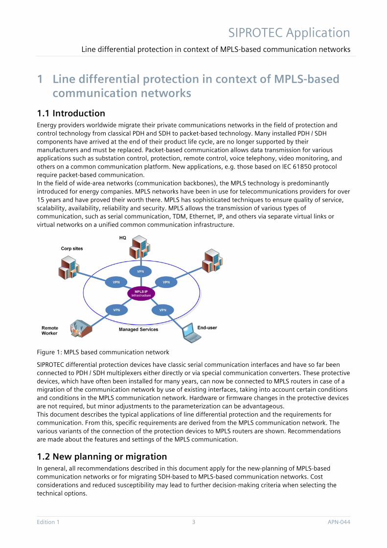
1.1 Introduction Energy providers worldwide migrate their private communications networks in the field of protection and control technology from classical PDH and SDH to packet-based technology. Many installed PDH / SDH components have arrived at the end of their product life cycle, are no longer supported by their manufacturers and must be replaced. Packet-based communication allows data transmission for various applications such as substation control, protection, remote control, voice telephony, video monitoring, and others on a common communication platform. New applications, e.g. those based on IEC 61850 protocol require packet-based communication. In the field of wide-area networks (communication backbones), the MPLS technology is predominantly introduced for energy companies. MPLS networks have been in use for telecommunications providers for over 15 years and have proved their worth there. MPLS has sophisticated techniques to ensure quality of service, scalability, availability, reliability and security. MPLS allows the transmission of various types of communication, such as serial communication, TDM, Ethernet, IP, and others via separate virtual links or virtual networks on a unified common communication infrastructure.
Figure 1: MPLS based communication network
SIPROTEC differential protection devices have classic serial communication interfaces and have so far been connected to PDH / SDH multiplexers either directly or via special communication converters. These protective devices, which have often been installed for many years, can now be connected to MPLS routers in case of a migration of the communication network by use of existing interfaces, taking into account certain conditions and conditions in the MPLS communication network. Hardware or firmware changes in the protective devices are not required, but minor adjustments to the parameterization can be advantageous. This document describes the typical applications of line differential protection and the requirements for communication. From this, specific requirements are derived from the MPLS communication network. The various variants of the connection of the protection devices to MPLS routers are shown. Recommendations are made about the features and settings of the MPLS communication.
1.2 New planning or migration In general, all recommendations described in this document apply for the new-planning of MPLS-based communication networks or for migrating SDH-based to MPLS-based communication networks. Cost considerations and reduced susceptibility may lead to further decision-making criteria when selecting the technical options.

SIPROTEC Application Line differential protection in context of MPLS-based communication networks
APN-044 4 Edition 1
Migration from SDH-based to MPLS-based communication networks
• The existing infrastructure consisting of the protection device and, if necessary, an external communication converter can be retained here if the network-side connection to the LER (Label Edge Router) is performed by a line card which supports the specific protocol (e.g. X.21, G703.1, G703.6 and C37.94).
New-planning of an MPLS-based communications network
• Eine schutzseitige C37.94 Wirkschnittstelle kann direkt, d.h. ohne externen Konverter, mit einer kompatiblen Line-Card eines LER (Label Edge Router) verbunden werden. Die direkte Kommunikation per Lichtwellenleiter (LWL) bietet zudem Schutz gegen elektromagnetische Störungen und eine erhöhte Verfügbarkeit (keine externe Komponenten). A C37.94 based protection interface can be used directly (without an external converter) to a compatible line card of an LER (Label Edge Router). Direct communication by means of optical fiber also offers protection against electromagnetic interference and increased availability (no external components).
1.3 Protection applications All common line differential protection topologies such as
• Traditional point-to-point connection (2-ends)
• Multi-end topologies
• Redundant connections (ring, hot standby)
can use connections via MPLS-based communications networks. Only a few settings are to be taken into account on the protective device side, which are affected by the configuration of the MPLS-based network (see chapter 1.3.3).
SIPROTEC line differential protection devices:
SIPROTEC 4: 7SD52/53, 7SD610
SIPROTEC 5: 7SD82/86/87, 7SL82/86/87
Redundancy of the communication paths
If communication redundancy (e.g., multi-end ring topology, hot standby) is required, two protection data communication links have to be applied at the protection devices (two interfaces per device) and independent communication paths.
1.3.1 Tripping time Depending on the application of the line differential protection within different voltage levels (distribution, sub-transmission, transmission) there are different requirements regarding the resulting tripping time. This is the summation result of the trip times specified by the manual in the technical data and additional latencies (signal propagation times) through the communication paths. The slowest communication path thus influences the resulting error clarification time.
Example: A tripping time of 30ms is required. The manual specifies a tripping time of 25ms for the relevant topology and the selected type of the output contact. On the network side, the sum of the delays in the network nodes + the sum of the propagation delay times in the links shall not exceed a time of 5 ms.

SIPROTEC Application Line differential protection in context of MPLS-based communication networks
Edition 1 5 APN-044
1.3.2 Asymmetrical propagation delay times Divergent signal transmission times in transmit and receive direction (asymmetry) shall be avoided as far as possible. Asymmetry disturbs the time synchronization between the differential protection devices and suggests a differential current which is not actually present. The remaining asymmetry must then be compensated by increased stabilization on the protection side.
SIPROTEC 4: Protection data interface parameters
• 4506 „PROT 1 UNSYM.“ for protection data interface 1
• 4606 „PROT 2 UNSYM.“ for protection data interface 2
SIPROTEC 5: Protection data interface parameters
• ___.5161.110 „Difference Tx and Rx time“ for the protection data interface
Important: Increased stabilization protects against mal operation, but leads to reduced sensitivity. The additional stabilization is calculated as follows
I Stab Asym = 2 Π f ∆T IRemote
mit:
𝑓 Rated frequency
∆𝑇 Time delta of sampling between local and remote
𝐼𝑅𝑒𝑚𝑜𝑡𝑒 Remote measured current
Protection – Setting recommendation
0,300ms (see also chapter 1.4.3)
It is necessary to consider whether the specific short-circuit currents (IRemote) of an application are still high enough to cause a trip. If the necessary sensitivity cannot be achieved, an external high precise time synchronization (e.g. GPS-PPS) has to be applied. In this case, separate external equipment for time synchronization is required:
• 7XV5664-1AA00 GPS/DCF77 Time Synch. Receiver
• 7XV5654-0BA00 SyncTransceiver (conversion: optical/elektrical)
1.4 Communication infrastructure requirements
1.4.1 Special requirements for line differential protection communication via MPLS networks
Communication failures
The transmission of line differential protection data messages should not be affected by interruptions and corruptions, as much as possible. Communication interruption and data corruption is recognized by the protection relays. Corrupted data messages are identified and withdrawn by help of the 32 bit CRC supervision. In case of interruption or data corruption the protection function waits for receiving valid data. These failures do not result in unwanted operation of the protection function but in decreased availability. Communication interruptions and message failure rates are indicated by alarms. The source of communication failures needs to be localized and fixed in case of measured failure rates higher than 1 percent.
Communication delay
The end-to-end communication delay (latency) (which consists of the summary residence time at the network nodes and summary propagation delay on the communication links) should not change over time and not

SIPROTEC Application Line differential protection in context of MPLS-based communication networks
APN-044 6 Edition 1
exceed approx. 5 ms. The delay does not impact the protection algorithm of the relays (as long as it is constant) but it is part of the overall tripping time. Therefore the communication delay should be minimized, as much as possible and feasible.
Asymmetric communication delay
Diverse delay values in sending and receiving direction (asymmetry) should be avoided or minimized as much as possible. Asymmetry disturbs the time synchronization of the protection relays which runs via the communication channel. It suggests a differential current which is not present in reality. The remaining asymmetry needs to be compensated by an increased stabilization (please see chapter 1.3.3).
Jitter
Packet delay variation (jitter) in MPLS networks disturbs the channel-based time synchronization between the protection relays. It suggests the variation of differential current which does not exist in reality. The packet delay variation has to be compensated on the network side (de-jittering).
Recommended network configurations: please see chapter 1.4.3 MPLS communication network
1.4.2 Interfaces SIPROTEC line differential protection relays can be equipped with serial optical protection interface modules. The interface modules provide ST connectors for multimode optical fibers with a wavelength of 820 nm. HDLC based framing is used for transmission of protection communication messages. The bitrate is up to 512 Kbit/s.
This proprietary interface can be connected to standardized MPLS router interfaces via Siemens communication converters. There are the following two options:
• Converter CC-2M (7XV5662-0AD00) for connection to electrical interface ITU-T G.703.6 E1 (2,048 MBit/s, for the world market) or G.703.6 T1 (1,554 MBit/s, for North America)
• Converter CC-XG (7XV5662-0AA00) for connection to electrical interface X.21 (with 64, 128, 256 or 512 KBit/s) or G.703.1 (with 64 KBit/s).
The same converter type and the same bitrate have to be used on both sides for the communication between peering protection relays.
Figure 2: Connection with serial optical protection interface via communication converter
SIPROTEC line differential protection relays can be equipped also with IEEE C37.94 optical interface modules. These interface modules contain ST connectors for multimode optical fibers with a wavelength of 820 nm. The protection communication messages are transmitted by help of a time slotted procedure according to IEEE C37.94. The bitrate is up to 512 Kbit/s.
The IEEE C37.94 interface of the protection relay can be connected by optical fiber directly to an MPLS router if latter supports this interface. The advantage is the direct optical connection, without conversion between optical and electrical.

SIPROTEC Application Line differential protection in context of MPLS-based communication networks
Edition 1 7 APN-044
Figure 3: Direct connection with IEEE C37.94 optical protection interface
The described interface variants have been used so far for the connection of SIPROTEC protection relays to PDH / SDH multiplexers. Existing deployments can be connected without any changes to MPLS routers in scope of communication network migration. The prerequisites are that the MPLS routers support the described interfaces and pseudo-wire emulation / circuit emulation via MPLS. This feature is needed for the transport of legacy serial or TDM based communication via a packet based network.
1.4.3 MPLS communication network
LER
LER
LSR
LSR
LSP
LER: Label Edge RouterLSR: Label Switch RouterLSP: Label Switch Path
Run Error SIPROTECs
52
52
52
BB1
BB2
Run Error SIPROTECs
52
52
52
BB1
BB2
SIPROTECLine Differential Protection
Relay SIPROTECLine Differential Protection
Relay
Figure 4: Line differential protection communication via MPLS network
MPLS packet forwarding
The MPLS router at the ingress side of the MPLS network (Label Edge Router – LER) inserts a label with a number to the packets before sending them to the network. The packet forwarding is done by help of the label from router to router (Label Switch Router – LSR) through the network to the egress LER. The packets of a certain communication context always follow the same path (the Label Switch Path – LSP) through the network. The sequence of packets is always preserved.
LSPs are unidirectional. Bidirectional communication requires a pair of LSPs, one for each direction. The two LSPs should be co-routed that means use the same routers and links through the network. As result, the data packets will traverse the same path in both directions. Asymmetric delay is mostly avoided. Nevertheless, a small delay asymmetry can appear in practice, especially in case of communication re-establishment after interruption.
Network requirement
Co-routed bidirectional LSPs should always be used for line differential communication over MPLS networks.

SIPROTEC Application Line differential protection in context of MPLS-based communication networks
APN-044 8 Edition 1
Protection configuration recommendation
It is recommended for compensation of the remaining delay asymmetry to set the corresponding parameter in the protection relays to 0.300 ms (please see chapter 1.3.1).
The LSP information is stored in the MPLS router label database. The label information has to be available before the communication starts. The label information can be distributed across the network by help of enhanced IP routing protocols or can be provided by configuration e.g. from a Network Management System (NMS).
Bandwidth reservation and prioritization
The user data communication is bound to LSPs in the LERs, e.g. by service configuration. Packet priority and bandwidth reservation can be assigned to user data communication in the MPLS network. High priority packets are preferred over low priority packets by the packet forwarding process in routers. This results in lower communication delay and jitter of high priority packets. The bandwidth reservation avoids packet losses caused by queue overflows in MPLS routers. Overall, these Quality of Service measures reduce the impact of low priority communication to the parallel running high priority communication.
Network requirement
The highest available user data priority should be applied for line differential protection communication via MPLS. Sufficient bandwidth has to be reserved. The packet overhead of the pseudo-wire transport has to be considered during bandwidth reservation.
Network recommendation
Links should not be occupied by more than 90 percent of their maximum bandwidth for limiting delay and jitter. Additional link bandwidth headroom of 10 ... 20 percent is recommended.
There are different MPLS flavors. MPLS-TE (Traffic Engineering) and MPLS-TP (Transport Profile) can be used for line differential communication, especially due to their Quality of Service capabilities. MPLS routers or MPLS capable network nodes of certain vendors might support either MPLS-TE or MPLS-TP only but not both.
MPLS-TE is based on enhanced IP routing protocols. The label switched paths are established automatically by help of the RSVP-TE reservation protocol. This is done using the information available in the routing database or following explicit path configuration in the MPLS routers.
Network requirement
LSPs should be explicitly configured for line differential communication over MPLS-TE so that the same path is used in both directions through the network (co-routed bidirectional LSPs). This is needed for minimizing the delay asymmetry which is undesired for the protection application.
MPLS-TE supports path redundancy with primary and secondary paths and special features like Fast Re-Route (FRR) for accelerated path switchover in case of failures. The minimum switchover time is on the level of 50 ms.
MPLS-TP can avoid using IP routing protocols. The label switched paths can be established by configuration in the MPLS network nodes, e.g. by a NMS. MPLS-TP supports also MPLS path redundancy and accelerated path switchover with minimum interruption time of 50 ms. MPLS-TP supports an extensive number of OAM (Operation, Administration and Maintenance) features.
Network recommendation
From the application perspective, MPLS-TE and MPLS-TP are likewise suitable for the protection communication transport.
SIPROTEC Application Line differential protection in context of MPLS-based communication networks
Edition 1 9 APN-044
Pseudowire / circuit emulation
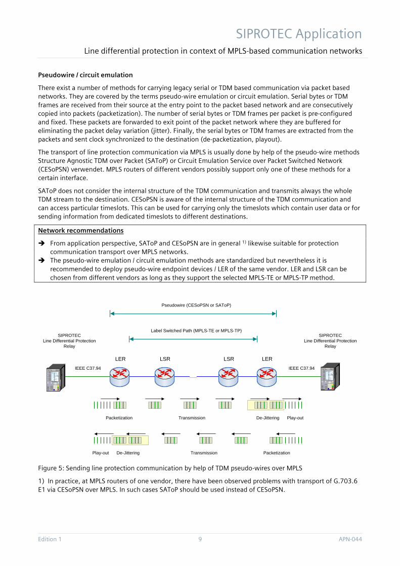
There exist a number of methods for carrying legacy serial or TDM based communication via packet based networks. They are covered by the terms pseudo-wire emulation or circuit emulation. Serial bytes or TDM frames are received from their source at the entry point to the packet based network and are consecutively copied into packets (packetization). The number of serial bytes or TDM frames per packet is pre-configured and fixed. These packets are forwarded to exit point of the packet network where they are buffered for eliminating the packet delay variation (jitter). Finally, the serial bytes or TDM frames are extracted from the packets and sent clock synchronized to the destination (de-packetization, playout).
The transport of line protection communication via MPLS is usually done by help of the pseudo-wire methods Structure Agnostic TDM over Packet (SAToP) or Circuit Emulation Service over Packet Switched Network (CESoPSN) verwendet. MPLS routers of different vendors possibly support only one of these methods for a certain interface.
SAToP does not consider the internal structure of the TDM communication and transmits always the whole TDM stream to the destination. CESoPSN is aware of the internal structure of the TDM communication and can access particular timeslots. This can be used for carrying only the timeslots which contain user data or for sending information from dedicated timeslots to different destinations.
Network recommendations
From application perspective, SAToP and CESoPSN are in general 1) likewise suitable for protection communication transport over MPLS networks.
The pseudo-wire emulation / circuit emulation methods are standardized but nevertheless it is recommended to deploy pseudo-wire endpoint devices / LER of the same vendor. LER and LSR can be chosen from different vendors as long as they support the selected MPLS-TE or MPLS-TP method.
.......
Pseudowire (CESoPSN or SAToP)
LERLER LSR LSR
Label Switched Path (MPLS-TE or MPLS-TP)
Run Error SIPROTECs
52
52
52
BB1
BB2
Run Error SIPROTECs
52
52
52
BB1
BB2
SIPROTECLine Differential Protection
Relay
SIPROTECLine Differential Protection
Relay
IEEE C37.94IEEE C37.94
Packetization Transmission De-Jittering Play-out
PacketizationTransmissionDe-JitteringPlay-out
Figure 5: Sending line protection communication by help of TDM pseudo-wires over MPLS
1) In practice, at MPLS routers of one vendor, there have been observed problems with transport of G.703.6 E1 via CESoPSN over MPLS. In such cases SAToP should be used instead of CESoPSN.

SIPROTEC Application Line differential protection in context of MPLS-based communication networks
APN-044 10 Edition 1
Communication delay
The overall communication delay is composed of the packetization delay at the pseudo-wire ingress point, the propagation delay of the communication links, the residence time at the network nodes on the communication path and the de-jitter buffer residence time at the pseudo-wire egress point.
The packetization and de-jittering creates significant delay. For example, the packetization rate of 16 C37.94 frames per MPLS packet results in 2 ms delay (125 µs framing-period * 16 frames = 2 ms). The de-jitter buffer is usually half occupied in average. If its depth is configured to 4 ms then the de-jitter buffer introduces 2 ms delay in average. In summary, the delay at the pseudo-wire endpoints can generate the most significant part of the overall communication delay. The pseudo-wire delay can be reduced by decreasing the packetization rate and the de-jitter buffer depth value.
There is a trade-off regarding low and high de-jitter buffer depth values. The buffer needs to be sufficiently dimensioned so that changes of the packet residence time in intermediate routers (e.g. caused by high traffic load) can be compensated and de-jitter buffer underruns or overflows (resulting in packet losses) are avoided. The traffic load in communication networks and this way the summary router residence time can be different in both directions and therefore the adequate dimensioning of the de-jitter buffer is important for reducing the overall path asymmetry.
Network recommendation
After consultation with the MPLS router vendor, the packetization rate and de-jitter buffer depth should be configured to the lowest feasible values for minimizing the communication delay. The maximum possible symmetric and asymmetric jitter values on the communication path have to be considered for de-jitter buffer depth dimensioning.
Synchronization
The TDM framing sent by the pseudo-wire endpoints (the LERs) to the protection relays has to be strictly synchronized between the peering sides. This is important for avoiding gradually changes of the end-to-end communication delay which can disturb the channel-based synchronization of the protection relays.
Network requirement
The pseudo-wire procedure requires high-quality synchronization across the participating network communication endpoints (MPLS network nodes).
The synchronization should be provided by central, high-precision and redundant clock sources (e.g. atomic clocks) in the communication network. The clock distribution can be done via the communication links, e.g. by help of IEEE 1588 PTP or ITU-T G.8262 Synchronous Ethernet or via a separate synchronization network, e.g. based on BITS. If IEEE 1588 PTP is used then all nodes of the MPLS network have to support this method (e.g. in the role of transparent clock).

SIPROTEC Application Line differential protection in context of MPLS-based communication networks
Edition 1 11 APN-044
CC-2M CC-2M.......
HDLC HDLCE1 (G703.6)
E1 (G703.6)
Communication Converter
Communication Converter
....... .......
Synchronization (Sync Eth or IEEE 1588 PTP)
Synchronization (Sync Eth or IEEE 1588 PTP)
Run Error SIPROTECs
52
52
52
BB1
BB2
Run Error SIPROTECs
52
52
52
BB1
BB2
SIPROTECLine Differential
Protection Relay
SIPROTECLine Differential
Protection Relay
Pseudowire
Label Switched Path
Figure 6: Centralized synchronization of LERs via MPLS communication paths
Communication path redundancy
MPLS-TE and MPLS-TP support MPLS path redundancy. It is based on two redundant MPLS paths per LSP which run via separate MPLS routers and links in the network. The primary path is used under normal conditions. The communication is switched over to the secondary path in case of router or link failure. The minimum communication interruption time is approx. 50 ms. The communication is switched back to the primary path after its restoration.
It was observed during tests and in practice that the switch-over and switch-back between primary and secondary paths can result in communication delay jumps and delay asymmetry. The reason for asymmetry are usually different levels of de-jitter buffer occupation at both sides after switching. The communication delay jumps and asymmetry can disturb the channel-based synchronization between the protection relays and should be avoided.
Redundancy requirements and recommendations
MPLS path redundancy should not be used for line differential protection communication. Instead, communication redundancy should be provided by help of the two protection interfaces of the
protection relays and separate communication paths through the network (ring topology, hot stand-by). The protection relays should be connected to two different LERs. If there is only one LER available then
the relays two protection interfaces should be connected to different line interface cards of the router. The router should be equipped with redundant central processor cards, network side interface cards, power supply and fan modules.
The redundant LSPs should use disjoint routers and paths through the communication network. Some MPLS network equipment vendors provide methods for avoiding or compensating delay asymmetry
caused by the de-jitter buffers. Even when using such features it is recommended to refrain from using MPLS path redundancy.

SIPROTEC Application Line differential protection in context of MPLS-based communication networks
APN-044 12 Edition 1
.......
CC-2M CC-2M.......HDLC HDLC
E1 (G703.6)
E1 (G703.6)
C37.94 C37.94
Pseudowire
Label Switched Path
Pseudowire
Label Switched Path
Run Error SIPROTECs
52
52
52
BB1
BB2
Run Error SIPROTECs
52
52
52
BB1
BB2
SIPROTECLine Differential
Protection Relay
SIPROTECLine Differential
Protection Relay
Communication Converter
Communication Converter
Figure 7: Redundant line differential protection communication via MPLS by help of two relay protection interfaces
1.5 Conclusion MPLS-based backbones enable energy companies to communicate with a wide range of requirements and features such as SCADA, IT, audio, video and teleprotection on a single communications infrastructure. MPLS networks can achieve a high quality of service and availability comparable to that of previous SDH networks. This requires careful planning, configuration and monitoring of the MPLS networks.
SIPROTEC differential protection devices with the classic, serial or TDM-based protection data interfaces can be connected to MPLS network nodes and the differential protection communication can be transported via the packet-based MPLS using Pseudowire emulation / circuit emulation.
For the application of an MPLS-based network, in the same way as for an SDH-based network, a correct protection behavior can be achieved in both cases (triggering time, sensitivity, availability) if the respective requirements are met in both cases.
Siemens recommends that the MPLS network be planned and configured in close co-ordination with the network equipment (s) and that the differential protection communication via MPLS is only activated after extensive tests.

SIPROTEC Application Line differential protection in context of MPLS-based communication networks
Edition 1 13 APN-044
1.6 Abbreviation BITS Building Integrated Timing Source
CESoPSN Circuit Emulation Service over Packet Switched Network
FO Fiber Optic FRR Fast Re-Route
HDLC High-level Data Link Control
IP Internet Protocol
LER Label Edge Router LSP Label Switched Path LSR Label Switch Router
MPLS Multiprotocol Label Switching MPLS-TE MPLS Traffic Engineering MPLS-TP MPLS Transport Profile
NMS Network Management System
OAM Operation, Administration & Maintenance
PDH Plesiochronous Digital Hierarchy
RSVP-TE Resource Reservation Protocol Traffic Engineering
SAToP Structure Agnostic TDM over Packet SDH Synchronous Digital Hierarchy
TDM Time Division Multiplex

APN-044 14 Edition 1
Published by Siemens AG 2017 Energy Management Division Digital Grid Automation Products Humboldtstr. 59
90459 Nuremberg, Germany
www.siemens.com/siprotec
For more information,
please contact our
Customer Support Center.
Tel.: +49 180 524 70 00
Fax: +49 180 524 24 71
(Charges depending on provider)
Email: [email protected]
© 2016 Siemens. Subject to changes and errors. The information given in this document only contains general descriptions and/or performance features which may not always specifically reflect those described, or which may undergo modification in the course of further development of the products. The requested performance features are binding only when they are expressly agreed upon in the concluded contract.
For all products using security features of OpenSSL, the following shall apply: This product includes software developed by the OpenSSL Project for use in the OpenSSL Toolkit. (http://www.openssl.org/ ) This product includes cryptographic software written by Eric Young ([email protected] ) This product includes software written by Tim Hudson ([email protected]) This product includes software developed by Bodo Moeller.