diesel fuel via the catalytic depolymerization · diesel fuel via the catalytic depolymerization....
TRANSCRIPT

Transformation of wastes material in Diesel, water and fertilizer
DIESEL FUEL VIA THE CATALYTIC DEPOLYMERIZATION

1. Introduction
1.1 Problems
1.2 Solution
2. Main Characteristics
2.1 Technology comparison
2.2 Technology by emissions.
3. Funcionamiento sistema Alphakat
3.1 Plant Summary
3.2 Inputs and feedstock
3.3 Production
3.4 Production benefits and highlights
3.5 Production Hoyersweda
4. Scenarios
4.1 Industrial installation MSW Tarragona
4.2 Example installation biomass waste
5. Economical figures
5.1 Break Even global
5.2 break Even per hour
6. Appendice A: CO” Calculation (german)
2
AGENDA

3
1. INTRODUCTION
Inventor Dr.-Ing. Christian Koch Born in 1940 since 1967 in Franken (germany). Studied Process/chemical engineering3 years associate professor at the engineering school then Reserch center SiemensSince 1973 KWU Erlangen (Brokdorf/Grohnde, Licenncing and aproval processes EVA), DevelopmentNew Energies from waste materials, Gasification and start of the oil transformation technology.Since 2003 Alphakat GmbH with the „Friktionsturbinen-Verölungstechnik KDV“ Construction of the plants Mexiko, Kanada, Hoyerswerda and Constanti/Tarragona (KDV 1.000)Since 2009 Development of new High performance turbines for a broad aplication spectrum (150 to 5.000 l/h Diesel)

4
1. INTRODUCTION1.1 Problems
Waste
CO2
Dioxines
Methane
Heat
Fuel problemEnergy Water
- More and more waste - CO2 rise (burning)- Methan rise (combustion)Heat production rise
Exa
mp
le C
O2
rise
dia
gra
ms

5
1. INTRODUCTION1.1 Problems
Waste
CO2
Dioxines
Methane
Heat
Fuel problemEnergy Consumption
Glo
bal
Oil
pro
du
ctio
n
Limited fossil fuel resourcesRising energy consumptionRising relevance of alternative energy sources
Energy b
y sou
rce

6
1. INTRODUCTION1.2 Solution
[19:43:10] Oliver Hartmann (TMT Factory): Accelerating 300 million years of the nature to 3 minutes with Alphakat100% crystalline catalyst istead of minerals280 – 330 Cº max temperature instead of natures 4Cº
Conversion organics to bitumen with minerals and extraction of oxygen in form of CO2
Depolymerization from bitumen to oil
Depolymerization from oil to Diesel
Step1
Step2
Step3
Step1
Step2
Step3
- Mixing: Calatyst mixed with material.- Adsorption: Docking of the catalist on material- Reaction: New formation of hydrocarbons (diesel)
Destilation of diesel and water from calayst oil
Spiltting catalyst from diesel
BY
NAT
UR
E: 3
00
Mill
. ye
ars
BY
ALP
HA
KA
T : 3
min
ute
s

7
1. INTRODUCTION1.2 Solution
+ production of diesel or production of electric energy (peak power)+ production of destilled waterSelfsufficient production process:No additianal water neededUses aprox 10% of the diesel produced
+ no dioxins+ no CO2 (CO2 is recycled except for the exhaust of the generator)+ all waste can be converted (except for glass, metal, porcelan, stones)+ low temperature/pressure process (low risk)+ heat is re-entered in the dehydration process (no heat pollution)The plant does not have a chimney

Application
• Fuel (diesel, cars, jet fuel)• Generator fuel for electricity (Peak Load)• Chemistry
ConclusionChanges convertible material into non-convertible material as a energy storage medium
82. MAIN CHARACTERISTICS
8
Inputs – Material
MSW (municipal solid waste)
All PlasticsAnimal waste Mineral oilsSewage SludgeAgricultural wasteBiomass cut material
Output
Diesel fuelDestilled waterAsh = fertilizer (1-3%)
CO2 (re-entered in the process)
Advantages:
• No emissions• No usable material necessary for the input• Efficiency (regarding the hydrocarbon content 65-90%)pending on the waterparts of the input material)• No temperature pollution with 300 degrees isolated in the production process

Conventional processes• Waste combustion
• Waste gasification
• Pyrolysis
9
9
2. MAIN CHARACTERISTICS2.1 Technology comparison
ALPHAKATChemical processesKDV (catalytic de-polimerization) Magnesium or aluminium silicate

Emissions Combustion Gasification Pyrolysis ALPHAKAT
CO2remark
100% - no firing added
80% - no FT-loss
50%- no methane consumption
10%- Own consumption
Dioxin Allowable limit Allowable limit Exceeds allowable limit No dioxins
Resins none Very problematic Very problematic None
Oil- and plastic residues
Emissions Combustion Gasification Pyrolysis ALPHAKAT
CO2remark
100% - no firing added
Not possible 50%- no methane consumption
10-20%- Own consumption
Dioxin Allowable limit n.a Exceeds allowable limit No dioxins
Resins none n.a. Very problematic none
Auto recycling material
10
10
2. MAIN CHARACTERISTICS2.1 Technology by emissions 1<2

Emissions Combustion Gasification Pyrolysis ALPHAKAT
CO2remark
100% - no firing added
80% - no FT-loss
50%- no methane consumption
10%- Own consumption
Dioxin Allowable limit Allowable limit Exceeds allowable limit No dioxins
Resins none Very problematic Very problematic none
Domestic waste predryed (no metal, glass or ceramic)
Emissions Combustion Gasification Pyrolysis ALPHAKAT
Energyconsumption
800-1500ºCDepending on input material
750-950ºCDepending on input material
450-950ºCDepending on input material
280-300ºC
General impact: Energy Consumption
11
11
2. MAIN CHARACTERISTICS2.1 Technology by emissions 2<2

12
12
3. SYSTEM FUNCTIONALITY3.1 Plant Summary
SLUDGEPLANT
KDVPLANT
ASHPLANT
GENSETPLANT
OPTIONALDESULPHURATION
PLANT

13
Particle size: Max 25mm diameter
Humidity: Max 20% weight
Inorganics: Max 5% weight
Calorific value
Optimal mix (biomass content)
Ash content
3. SYSTEM FUNCTIONALITY3.2 Inputs and feedstock
MSW (municipal solid waste)All PlasticsAnimal waste Mineral oilsSewage SludgeAgricultural wasteBiomass cut material
OUTPUT
• Diesel quality 65 “Cetan” (20% more efficient
compared to the diesel of a regular gas station)
• Lower freezing point aprox. -60 Cº
• Distilled Water
• 1-3% ash (fertilizer) binds hazardous
materials
PRODUCTION:
1,2 t biological mass = aprox 500L diesel
depending on the water saturation.
• NO chimney necesarry
• NO heat pollution
• NO Methane / CO2
• NO Dioxine
WA
ST
E T
RE
AT
ME
NTINPUTS
FEEDSTOCK

14
14
143. SYSTEM FUNCTIONALITY3.3 Production
PROCESS (after feedstock Input)
Process 1: Mixing, Adsorption, Reaction: - Mixing: Calatyst mixed with material.
Motor (consumption 3-10% of production)a diesel or electric motor or a gas turbine is used (helicopter)Turbine creates heat via friction of high speed revolutions
- Adsorption: Docking of the crystalized ion-exchanged catalist on the molecular bindings of the material
- Reaction: Molecular bundings are broken and formed new into saturaded hydrocarbon molecules without Oxygen
Process 2: Desorption Hydration and spilitting of the catalist from the diesel , water and ash
Process 3: Evaporation Destillation of the diesel and water.
- Diesel pumped in Tanks for quality control
- Catalist refreshed
Process 4 (optional): Hydrofiner seperates sulphur residues if necessary
SIZE
150 l/h 500 l/h1000 l/h2000 l/h5000 l/hmodular
PARAMETER
PH9Depression 0,5 barTemp. Max 320 CºNo chimney
PLANT DIMENSIONS*
500 l/h = 25 x 25 x 10 m2000 l/h = 50 x 50 x 30 m5000 l/h = 100 x 100 x 30 m
(*) without transport, storage or separation logistics

15
15
153. SYSTEM FUNCTIONALITY3.4 Production benefits and highlights
BENEFITS
HIGHLIGHTS
•The technological reproduction of the natural crude oil synthesis is accomplished within minutes•Synthetic fuel can be produced at competitive prices•The quality of ALPHAKAT-Diesel fuel is better than the EU-standards for conventional diesel fuel.•No environmental pollution. The technology binds inorganic harmful substances in salt induced bythe ionic changing characteristics of the catalyst.•Environmental protection becomes a source of energy and jobs.
•The ALPHAKAT process can use all materials containing hydrocarbons with reduced content of water and inorganics•The efficiency is regarding to the low reaction temperature (280 – 320ºC), and high conversion rates (about 65 – 85 %)•The plant does not produce coke and needs no cleaning system.•The plant has not heating systems. The heat is coming from the friction in the turbine avoiding hot surfaces that can ignite materials. •The vacuum controls the safety of the plant and the input system•The residue is produced in solid form and offers the opportunity for the recycling of the catalyst •The consumption of the catalyst is very low and the cost of the process is very competitive.

16
16
3. SYSTEM FUNCTIONALITY3.5 Production Hoyersweda

17
17
4. SCENARIOS4.1 Industrial installation MSW Tarragona
Plant building with control center and electricity generators
Waste pretreatment plant: cleaning & shreddingFeedstock storage and transport conveyorsFeedstock hopper and dosifier
Characteristics:• Recycable plastics are separated and sold• Organic waste is pre-composted (dehydrated)• Diesel generators to create electricity to operate all components and vehicles of the plant
Alphakat Plan with connection to diesel tanks

18
18
4. SCENARIOS4.2 Example instalation biomass waste
Plant building with control center and electricity generators
Dehydration plant: drying & shreddingFeedstock storage and transport conveyorsFeedstock hopper and dosifier
Characteristics:• Modified feedstock preparation process•Lower feedstock preparation costExamples:- Sugar cane residues, sewr sludge, contaminated/oily soil/sand, “biofuel” plant mass, mineral oil residues, etc.
Alphakat Plan with connection to diesel tanks

Biomass examples:• Sewer sludge
• Forrest waste
• Agricultural waste
• Energy through photosynthesis
“biofuel-” plants as source of feedstock
▫ Plant deserts and cities with new type of plants as “Jatropha” having roots up to 10 m.
▫ Harvest the plants without destruction and without implications on the food chain.
▫ Create new jobs in planting, harvesting and conversion in diesel
▫ Create social structures
19
19
4. SCENARIOS4.2 Example instalation biomass waste
Jatropha Sugar cane waste Palm oil waste
-1000 has.-8,000 tons Diesel per year
-1000 has.-9,000 tons Diesel per year
-1000 has.-7,000 tons Diesel per year

20
20
5. ECONOMICAL FIGURES5.1 Break Even global
TRESORY/DEBT Year 1 Year 2 Year 3 Year 4 Year 5 Year 6 Year 7 Year 8 Year 9 Year 10
Incomes 6.624 6.624 6.624 6.624 6.624 6.624 6.624 6.624 6.624 6.624
Outcomes 4.363 4.380 4.398 4.417 4.438 4.459 4.482 4.506 4.531 4.558
Cash Flow period 2.261 2.244 2.226 2.207 2.186 2.165 2.142 2.118 2.093 2.066
Working capital 0
Tresory 2.261 4.505 6.731 8.937 11.124 13.289 15.431 17.550 19.643 21.709
Long term loan Balance 11.933 10.884 9.775 8.601 7.360 6.048 4.660 3.193 1.641 0
0
5.000
10.000
15.000
20.000
25.000
1 2 3 4 5 6 7 8 9 10
Cash Flow accumulated Long term loan Balance

21
21
5. ECONOMICAL FIGURES5.2 Break Even per hour
-500.000
0
500.000
1.000.000
1.500.000
2.000.000
2.500.000
3.000.000
3.500.000
4.000.000
2.120 1.920 1.720 1.520 1.320 1.120 920 720 520
Earn
ingsBreakeven Liters/Hour
Breakeven: 1,120 liters/hour ( 62% expected production)
APPENDICE A: CO2 CALCULATION
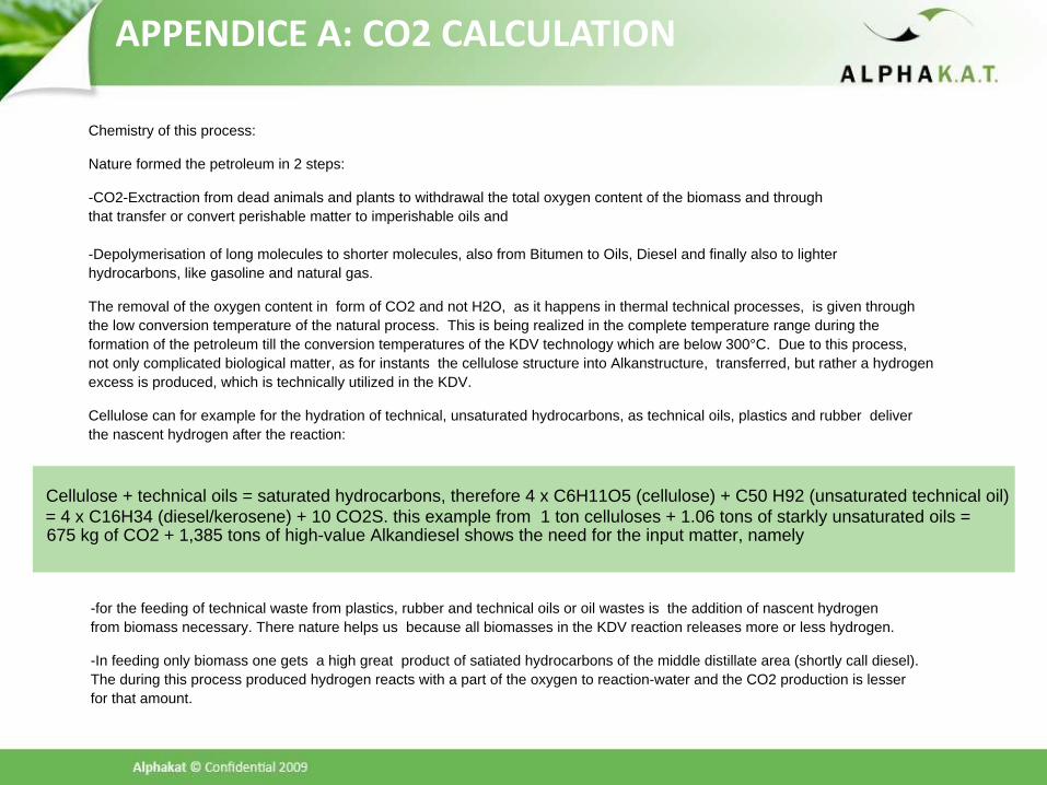
Chemistry of this process:
Nature formed the petroleum in 2 steps:
-CO2-Exctraction from dead animals and plants to withdrawal the total oxygen content of the biomass and through that transfer or convert perishable matter to imperishable oils and
-Depolymerisation of long molecules to shorter molecules, also from Bitumen to Oils, Diesel and finally also to lighter hydrocarbons, like gasoline and natural gas.
The removal of the oxygen content in form of CO2 and not H2O, as it happens in thermal technical processes, is given throughthe low conversion temperature of the natural process. This is being realized in the complete temperature range during theformation of the petroleum till the conversion temperatures of the KDV technology which are below 300°C. Due to this process, not only complicated biological matter, as for instants the cellulose structure into Alkanstructure, transferred, but rather a hydrogen excess is produced, which is technically utilized in the KDV.
Cellulose can for example for the hydration of technical, unsaturated hydrocarbons, as technical oils, plastics and rubber deliver the nascent hydrogen after the reaction:
Cellulose + technical oils = saturated hydrocarbons, therefore 4 x C6H11O5 (cellulose) + C50 H92 (unsaturated technical oil) = 4 x C16H34 (diesel/kerosene) + 10 CO2S. this example from 1 ton celluloses + 1.06 tons of starkly unsaturated oils = 675 kg of CO2 + 1,385 tons of high-value Alkandiesel shows the need for the input matter, namely
-for the feeding of technical waste from plastics, rubber and technical oils or oil wastes is the addition of nascent hydrogen from biomass necessary. There nature helps us because all biomasses in the KDV reaction releases more or less hydrogen.
-In feeding only biomass one gets a high great product of satiated hydrocarbons of the middle distillate area (shortly call diesel). The during this process produced hydrogen reacts with a part of the oxygen to reaction-water and the CO2 production is lesser for that amount.

APPENDICE A: CO2 CALCULATION
The KDV reaction is therefore always
1.a diffusion catalytic new formation of the molecule structure 2.with the extract ions of the oxygen content as a CO2, 3.adsorption of the molecular fine catalyst through Antransport with the catalyst oil at the brought hydrocarbon mass 4.without Koksablagerung 5.without Dehydrierung 6.without resin material development 7.in a continuous process 8.under development of satiated hydrocarbons 9.under avoidance of Olefinen 10.under avoidance of aromas and therewith the possibility of dioxin or Furanbildung 11.in the ion exchange removing of the acids halogens and sulfur and 12.regeneration of the catalyst with chalk
In the reaction steps of the KDV 1.entry systems 2.before process technology of the transformation of the festival materials into a pulp under complete draining ({PN200 - 220°PN}C) 3.KDV process with "friction turbine" under release of the hydrocarbons as a means distillate and the remaining CO2-Menge and 4.ash plant to the Limitierung of the salt salary and the not marketable inorganic materials in the KDV (metal, glass, ceramics, stones) and 5.in request after desulfurization (Hydrofiner)
Transformation of organic materials
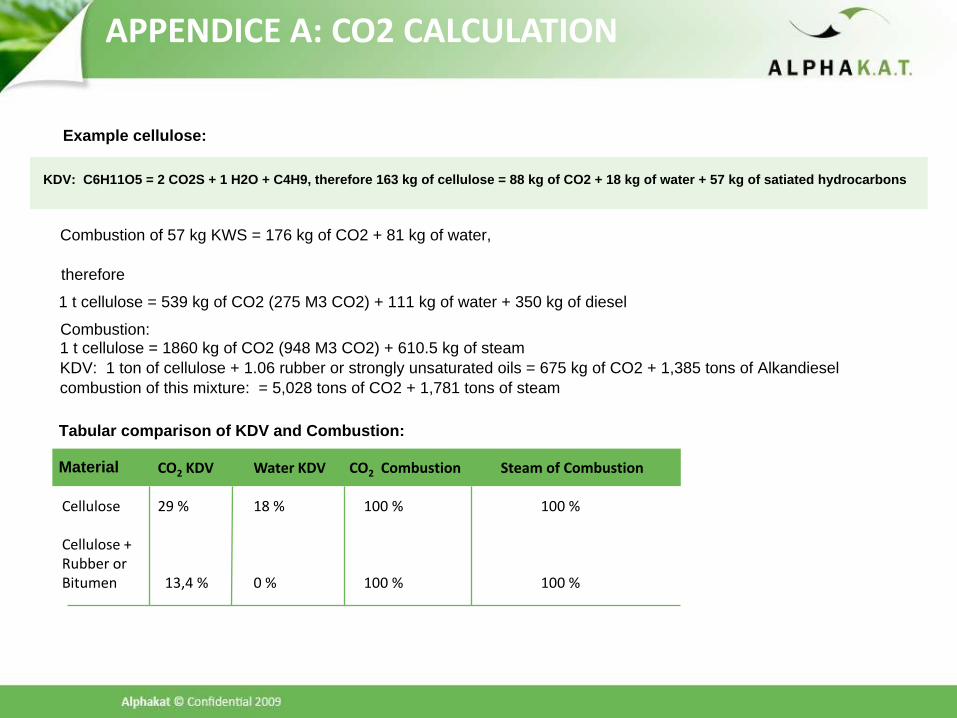
CO2 KDV Water KDV CO2 Combustion Steam of Combustion
Cellulose 29 % 18 % 100 % 100 %
Cellulose +Rubber or Bitumen 13,4 % 0 % 100 % 100 %
APPENDICE A: CO2 CALCULATION
Example cellulose:
KDV: C6H11O5 = 2 CO2S + 1 H2O + C4H9, therefore 163 kg of cellulose = 88 kg of CO2 + 18 kg of water + 57 kg of satiated hydrocarbons
Combustion of 57 kg KWS = 176 kg of CO2 + 81 kg of water,
therefore
1 t cellulose = 539 kg of CO2 (275 M3 CO2) + 111 kg of water + 350 kg of diesel
Combustion:1 t cellulose = 1860 kg of CO2 (948 M3 CO2) + 610.5 kg of steam KDV: 1 ton of cellulose + 1.06 rubber or strongly unsaturated oils = 675 kg of CO2 + 1,385 tons of Alkandiesel combustion of this mixture: = 5,028 tons of CO2 + 1,781 tons of steam
Tabular comparison of KDV and Combustion:
Material