diatom frustule-filled epoxy: experimental and … · diatom frustule-filled epoxy: experimental...
TRANSCRIPT

A
pteqtsr©
K
1
mmtfDafistapsr
IT
0d
Materials Science and Engineering A 480 (2008) 373–382
Diatom frustule-filled epoxy: Experimental and numerical studyof the quasi-static and high strain rate compression behavior
A. Tasdemirci a, S. Yuksel a, D. Karsu a, E. Gulturk a, I.W. Hall b, M. Guden a,c,∗a Department of Mechanical Engineering, Izmir Institute of Technology, Gulbahce Koyu, Urla, Izmir, Turkey
b Department of Mechanical Engineering, University of Delaware, Newark, DE, USAc Center for Materials Research, Izmir Institute of Technology, Gulbahce Koyu, Urla, Izmir, Turkey
Received 10 March 2007; received in revised form 5 July 2007; accepted 6 July 2007
bstract
In this study, centric type diatom frustules obtained from a diatomaceous earth filter material were used as filler in an epoxy resin with a weightercentage of 15% in order to assess the possible effects on the compressive behavior at quasi-static and high strain rates. The high strain rateesting of frustule-filled and neat epoxy samples was performed in a split-Hopkinson pressure bar (SHPB) set-up and modeled using the commercialxplicit finite element code LS-DYNA 970. Result has shown that 15% frustule filling of epoxy increased both modulus and yield strength values atuasi-static and high strain rates without significantly reducing the failure strain. Microscopic observations revealed two main deformation modes:
he debonding of the frustules from the epoxy and crushing/fracture of the frustules. The modeling results have further confirmed the attainment oftress equilibrium in the samples in SHPB testing following the initial elastic region and showed good agreement with the experimental stress–timeesponse and deformation sequence of the samples in high strain rate testing. 2007 Elsevier B.V. All rights reserved.ate
omnwt
tavstbp
eywords: Diatom frustules; Frustule-filled epoxy; Compression; High strain r
. Introduction
Diatoms are single-celled algae, living in aquatic environ-ents [1]. The shell of the diatoms, known as a frustule, isade of nano-sized silica particles with an intricate 3D struc-
ure. When these aquatic plants cells die, the silica shell/frustulesorm diatomaceous earth (diatomite) on the floor of the ocean.iatomaceous earth is an abundant, extremely cheap material
nd extensively used in sound and heat insulation, abrasives,lters, absorbents, and explosives [2]. Recent studies have alsohown that intricate microscale polymeric and ceramic struc-ures including zirconia [3,4], gold nanostructures [5] and MgOnd TiO2 structures [6] can be prepared with relatively sim-
le processing steps using the diatom frustules as transientcaffolds, templates and in solid–gas displacement reactions,espectively. The potential engineering and medical applications∗ Corresponding author at: Department of Mechanical Engineering, Izmirnstitute of Technology, Gulbahce Koyu, Urla, Izmir, Turkey.el.: +90 232 750 7816; fax: +90 232 750 7890.
E-mail address: [email protected] (M. Guden).
serd1meso
921-5093/$ – see front matter © 2007 Elsevier B.V. All rights reserved.oi:10.1016/j.msea.2007.07.037
f diatom frustules have also recently been proposed, includingetal film membranes, pinpoint drug delivery and processing of
anopowder silica [7]. The surface area of diatomaceous earthas reported to be relatively high, 22 m2/g [8] and it was shown
o decrease slightly as a result of heat-treatment [9].Owing to the high surface area/volume ratio, diatom frus-
ules may have potential for use as the reinforcing phasend/or filler in polymeric composites: this provided the moti-ation for the present study. Thermoset resins have also beenhown to penetrate through the micropores of diatom frus-ule, showing the capability of forming mechanical interlockingetween frustule and polymer matrix [3]. The mechanicalroperties of individual diatom frustules have also been mea-ured recently using atomic force microscopy (AFM). Thelastic modulus of the diatom frustule of T. punctigera waseported as 22.4 GPa [10]. The modulus and hardness ofiatom Navicula pelliclosa varied between 7 and 100 GPa andand 12 GPa, respectively, depending on the location of the
easurements taken [11]. The variation in the mechanical prop-rties of the diatom frustule is closely related to the differenttages of the biomineralization process. Despite the absencef plastic deformation and the smooth fracture surfaces of
3 e and Engineering A 480 (2008) 373–382
tnsaf
ahtufaeoqtbasordotmr
2
2
tEiaotcwaF
c(facacarppTrpAoftom
2
74 A. Tasdemirci et al. / Materials Scienc
he broken frustule, it was microscopically shown in a pen-ate diatom that the cracks traveled around the nano-silicapheres, ∼40 nm, of the diatom frustule [12], increasing therea of the fracture and, hence, the energy needed to break therustule.
The properties of polymers are known to be improved by theddition of various types of micron and nano-sized fillers. Fillersaving high surface area/volume ratio are generally expectedo result in better mechanical properties. High surface area issually associated with small filler size and with very rough sur-aces. In this study, centric type diatom frustules obtained fromdiatomaceous earth filtering materials are used as filler in an
poxy resin in order to assess the possible effects of the frustulen the mechanical properties under compressive loads at bothuasi-static and high strain rates. Such filled polymer can poten-ially be used as the matrix for the fiber reinforced compositeacking plate of modern composite armor in which the energybsorption capabilities of the composite at quasi-static and hightrain rates play a critical role in absorbing the kinetic energyf the projectiles [13]. The development of multi-layer mate-ial systems, consisting of hard and soft layers, also requiresetailed experimental and numerical wave-propagation analysisf the individual layer materials [14]. Therefore, the deforma-ion behavior of the filled composite and its neat matrix was
odeled for possible future applications involving high strainate deformation.
. Materials and testing methods
.1. Diatom frustules
The diatom frustules, obtained as diatomaceous earth fil-er material from a local vendor (Celatoms FW-60 grade fromaglePicher Filtration & Mineral Inc.), were mostly cylindrical
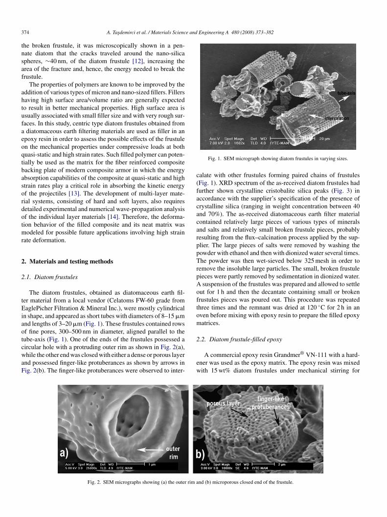
n shape, and appeared as short tubes with diameters of 8–15 �mnd lengths of 3–20 �m (Fig. 1). These frustules contained rowsf fine pores, 300–500 nm in diameter, aligned parallel to theube-axis (Fig. 1). One of the ends of the frustules possessed a
ircular hole with a protruding outer rim as shown in Fig. 2(a),hile the other end was closed with either a dense or porous layernd possessed finger-like protuberances as shown by arrows inig. 2(b). The finger-like protuberances were observed to inter-
ew
Fig. 2. SEM micrographs showing (a) the outer rim a
Fig. 1. SEM micrograph showing diatom frustules in varying sizes.
alate with other frustules forming paired chains of frustulesFig. 1). XRD spectrum of the as-received diatom frustules hadurther shown crystalline cristobalite silica peaks (Fig. 3) inccordance with the supplier’s specification of the presence ofrystalline silica (ranging in weight concentration between 40nd 70%). The as-received diatomaceous earth filter materialontained relatively large pieces of various types of mineralsnd salts and relatively small broken frustule pieces, probablyesulting from the flux–calcination process applied by the sup-lier. The large pieces of salts were removed by washing theowder with ethanol and then with dionized water several times.he powder was then wet-sieved below 325 mesh in order to
emove the insoluble large particles. The small, broken frustuleieces were partly removed by sedimentation in dionized water.suspension of the frustules was prepared and allowed to settle
ut for 1 h and then the decantate containing small or brokenrustules pieces was poured out. This procedure was repeatedhree times and the remnant was dried at 120 ◦C for 2 h in anven before mixing with epoxy resin to prepare the filled epoxyatrices.
.2. Diatom frustule-filled epoxy
A commercial epoxy resin Grandmer® VN-111 with a hard-ner was used as the epoxy matrix. The epoxy resin was mixedith 15 wt% diatom frustules under mechanical stirring for
nd (b) microporous closed end of the frustule.

A. Tasdemirci et al. / Materials Science
Fc
3wgctmfoTmdswdfim1na9s
2
Acaaabfiit
ε
ε
σ
wltsasle
σ
wsartteSieo
tgmmasotsutst
2
ttsctsat
ig. 3. XRD spectrum of the diatom frustule used in epoxy matrix showingristobalite diffraction peaks.
0 min at 100 rpm. After degassing under vacuum, the hardeneras added, and the solution was gently mixed in order to avoidas bubble formation. The polymer/frustule mixture was thenast into an 8 cm × 8 cm × 1.5 cm steel mold. The mixture washen cured at room temperature under vacuum inside the steel
old for 24 h followed by a post-curing treatment at 110 ◦Cor 2 h. Using the above procedure, 8 cm × 8 cm × 1.5 cm platesf neat epoxy and diatom frustule-filled epoxy were prepared.he densities of epoxy and diatom frustule-filled epoxy wereeasured to be 1.123 and 1.21 g cm−3, respectively, by simply
ividing the weight of the small cylindrical compression testpecimens by their volume. The volume percentage of the filleras calculated to be ∼8% using the producer specified fillerensity (2.33 g cm−3). Applying the rule of mixtures gives alled epoxy density of 1.3 g cm−3, which is 8% higher than theeasured density. Cylindrical samples 9.78 mm in diameter and
4 mm in length were core-drilled perpendicular to the thick-ess direction for compression testing and compression testedt quasi-static strain rate of 0.0011 s−1 and high strain rates of50–1000 s−1 and 1450–1550 s−1 in the split-Hopkinson pres-ure bar (SHPB) apparatus.
.3. Quasi-static and high strain rate testing
Quasi-static compression tests were performed in a ShimadzuG-I testing machine, while the high strain rate tests wereonducted using a compression SHPB apparatus. The SHPBpparatus used consists of 19.05 mm diameter Inconel 718 bar,3450 mm long incident bar and 1850 mm long transmitter bar,nd either a 356 or 712 mm long striker bar. The smaller strikerar was used to attain higher strain rates in the sample with lowernal strains. Detailed information about the SHPB used is given
n Ref. [14]. The strain rate (ε), the strain (ε) and the stress (σ) of
he tested sample were calculated using the following equations:˙(t) = −2Cb
Lsεr(t) (1)
mtnw
and Engineering A 480 (2008) 373–382 375
(t) = −2Cb
Ls
∫ t
0εr(t) (2)
(t) = EbAb
Asεt(t) (3)
here Cb is the elastic wave velocity in the bar, Ls the sampleength, As and Ab are the sample and bar cross-sectional areas andis the time, respectively. εr and εt are reflected and transmittedtrains measured from strain gages on the bar, respectively. Thebove equations are based on the assumption that the forces atample–bar interfaces are equal. The experimental force equi-ibrium for the same incident and transmitter bars diameter isxpressed as
t(t) = σi(t) + σr(t) (4)
here σt, σi and σr are the transmitted, incident and reflectedtresses, respectively. The left and right sides of this equalityre used in the so-called “one-wave” and “two-wave” analyses,espectively. Stress equilibrium within the sample is consideredo be reached after three to five back and forth reflections ofhe wave in the sample and the time at which equilibrium isstablished depends on the wave transit time of the sample [15].ince the transmitter bar of the used SHPB is shorter than the
ncident bar, the tensile wave reflected from the transmitter barnd separates the bars and, therefore, the sample deforms onlynce under compression.
Composite samples, compressed to various strains and upo failure at quasi-static and high strain rates, were metallo-raphically prepared for microscopic analysis. Typical damageechanisms operative prior to and during the failure were deter-ined using microscopy techniques. The deformation process
t high strain rates was observed by photographing the specimenequentially in predetermined short time intervals (of the orderf few microseconds) using a high-speed camera during SHPBesting. With the Ultra 8 high-speed camera used for the presenttudy, a maximum of eight frames can be photographed at speedsp to 100 million frames/s. In the time domain, the interframeime can be varied between 10 ns and 1 ms. The camera can beynchronized with the incident bar strain-gage or can be delayedo photograph the events of interest only.
.4. Modeling high strain rate deformation
A three-dimensional SHPB finite element model was usedo study the dynamic deformation behavior and stress–state ofhe diatom frustule-filled and neat epoxy specimens. The analy-es were performed using the commercial explicit finite elementode LS-DYNA 970. For each test modeled, the force and, hence,he stress values were calculated at several locations within theample, including the sample front and back surfaces, as well ast the location of the strain gages on the incident and transmit-er bars of the SHPB apparatus. The results calculated from the
odel were compared with the output from the strain gages onhe incident and transmitter bars. The model has three compo-ents in contact: the incident and transmitter bars (the lengths ofhich are 3450 and 1850 mm, respectively), and the specimen.

376 A. Tasdemirci et al. / Materials Science and Engineering A 480 (2008) 373–382
Fs
Tmocma
Table 1Material properties used in Finite Element Models
Material Modulus ofelasticity (GPa)
Poissonratio
Density(kg m−3)
Proportionallimit (MPa)
Epoxy 3.46 0.35 1133.0 113.0Diatom-filled epoxy 3.94 0.35 1206.0 128.4I
7pobtm
tmicdr
Ft
ig. 4. The SHPB testing model of the incident and transmitter bars and thepecimen (only specimen–bar interfaces section are shown).
he bar diameter is 19.05 mm and the diameter of the speci-en is 9.78 mm. Two axes of symmetry were assumed therefore
nly one quarter of the bar was modeled as shown in Fig. 4. Theomponent materials were modeled with eight nodes solid ele-ents and the bar–specimen interfaces were modeled with the
utomatic contact sliding interfaces without friction. A total of
[uws
ig. 5. SEM micrographs of the diatomaceous earth/epoxy matrix showing (a) distrihe frustule tube axis) and (c) the wall of a frustule. C denotes compression axis and
nconel 207.0 0.30 7850.0 –
5 elements were used in the model for the cross-section, whichrovided 10 elements across the radius of the bars and a totalf 400 elements were used along the length of the bar. Meshiasing along the bar axis was utilized to refine the meshes athe contact interfaces. Further details of the modeling procedure
ay be found elsewhere [14].The material properties used in the finite element code are
abulated in Table 1. The neat and frustule-filled epoxy wereodeled with a piecewise linear plasticity material model which
s an elasto-plastic material model with an arbitrary stress–strainurve and in which an arbitrary strain rate dependency can beefined. A fully viscoplastic formulation is optional for the mate-ial model and this option was used throughout the calculations16]. Experimentally generated stress versus strain curves are
sed as input to LS-DYNA. The Inconel bars were modeledith an isotropic elastic material model. Force equilibrium in thepecimen is further checked numerically using a dimensionless
bution of the frustules in the matrix, (b) completely filled frustules (normal toT thickness of the epoxy plate.

ience and Engineering A 480 (2008) 373–382 377
n
R
wfdfg
3
3
niaraontwFatfiote
caasey
Fg
Fig. 7. Compression stress–strain graphs of (a) neat epoxy and (b) frustule-filled
A. Tasdemirci et al. / Materials Sc
umber, R [15]:
= −2(F1 − F2)
F1 + F2(5)
here F1 and F2 are the SHPB test sample front and back surfaceorces, respectively. This number is a measure of the extent ofeviation from stress equilibrium in the specimen, which canurther be compared with the experimental force equilibriumiven in Eq. (4).
. Results and discussion
.1. Microstructure and deformation behavior
Fig. 5(a) shows diatom frustule distribution through the thick-ess of the prepared frustule-filled epoxy plate. In this (contrastnverted) scanning electron microscope (SEM) micrograph, Cnd T refer the compression axis and thickness directions,espectively. It is noted in Fig. 5(a) that the frustules’ tube-axesre preferentially aligned in the plane normal to the thicknessf the plate as relatively few are aligned through the thick-ess, showing a nearly planar random tube-axis distribution inhe plane normal to the plate thickness. The compression testsere, therefore, conducted parallel to the planar random plane.ig. 5(b) shows two diatom frustules whose tube axes wereligned normal to the thickness of the plate. It is also seen inhe same figure that the interiors of the tubes are completelylled with epoxy resin. A 500 nm thick tube-wall cross-sectionf a diatom frustule is further shown in Fig. 5(c). The pores onhe frustule wall are seen to be completely infiltrated with thepoxy resin.
Typical SHPB engineering stress/strain and strain rate/strainurves of the filled epoxy are shown in Fig. 6. The sample failedt a strain of 0.28. For a specific test, the strain rate becomes
lmost constant following the yield stress as also shown in theame figure. It is also noted in Fig. 6 that the force or stressquilibrium is attained at strains about 0.05 (corresponding toield stress) at which the one- and two-wave solutions becomeig. 6. Typical SHPB one- and two-wave stress–strain and strain rate–strainraphs of filled epoxy matrix tested at 950 s−1 until the failure strain of ∼0.28.
epoxy at quasi-static and dynamic strain rates.
Fig. 8. Comparison of stress–strain curves of epoxy and frustule-filled epoxyand similar strain rates (samples tested until failure).

378 A. Tasdemirci et al. / Materials Science and Engineering A 480 (2008) 373–382
F y test0 train.
asprflpfi
firmmfaf3r
s5ticf
stffhq
TM
P
EYFF
ig. 9. SEM micrographs of the polished cross-sections of the quasi-staticall.0011 s−1 until 48% strain and (c) and (d) sample tested at 950 s−1 until 27% s
lmost equal. Fig. 7(a) and (b) shows the typical compressivetress/strain curves of the neat epoxy and filled epoxy sam-les tested at quasi-static (0.0011 s−1) and the high strain rates,espectively (950–1550 s−1). For both samples, the yield andow stresses increased significantly at high strain rates, clearlyroving the matrix dominated high strain rate behavior of thelled epoxy.
In Fig. 8, the stress–strain curves of epoxy and frustule-lled epoxy samples are shown for comparison at similar strainates. At both strain rates, filled-composite samples show higherodulus, yield and flow stresses than those of neat epoxy. Theeasured average mechanical properties of the neat epoxy and
rustule-filled epoxy, elastic modulus, yield and failure stresses
nd failure strain are tabulated in Table 2. As tabulated, therustule addition increases elastic modulus and yield stress by5% and 15% at 0.0011 s−1 and 14% and 8% at 950–1000 s−1,espectively. It is also noted in Table 2 that although the failureorah
able 2echanical properties of epoxy and diatom frustules filled epoxy at quasi-static and
roperty Epoxy quasi-static(0.0011 s−1)
Epoxy high strarate (1000 s−1)
lastic modulus (GPa) 1.29 (1.28–1.30) 3.46 (3.4–3.5ield stress (MPa) 51.8 (51–53) 158 (155–160)ailure stress (MPa) 135 (120–145) 134 125–145ailure strain 0.542 (0.535–0.543) 0.286 (0.28–
ed and recovered frustule-filled epoxy samples: (a) and (b) Sample tested at
trains of the epoxy and frustule-filled epoxy decreased about0% at high strain rate compared to the quasi-static strain rate,his was a strain rate effect and not linked to the frustule additiontself. In fact, frustule addition did not itself lead to any signifi-ant decrease in failure strain of the epoxy at the studied volumeractions.
Fig. 9(a) shows an SEM micrograph of a frustule-filled epoxyample tested at 0.0011 s−1 to a strain of 48%. As a result ofhe compressive loading, the frustules’ tubes undergo severeragmentation in the deformed sample as compared with unde-ormed sample shown in Fig. 5(a). This also partly proves theomogeneous loading of the frustules during compression untiluite large strains. The failure mechanism of the filled epoxy is
bserved to be debonding of the frustule walls from the epoxyesin at both quasi-static and high strain rates as seen in Fig. 9(b)nd (c). Fig. 9(d) shows crack progression in a sample tested atigh strain rates through a shear band region at ∼45◦ to the load-high strain rates
in Diatom frustule/epoxyquasi-static(0.0011 s−1)
Diatom frustule/epoxyhigh strain rate (950 s−1)
5) 1.75 (1.7–1.8) 3.94 (3.91–3.97)59.6 (58.6–60.7) 171 (170–173)
189 (182–197) 159 (155–163)0.29) 0.54 (0.52–0.56) 0.273 (0.27–0.276)
ience and Engineering A 480 (2008) 373–382 379
it
ffopotFft(sitrFstisit
sait
F
A. Tasdemirci et al. / Materials Sc
ng axis. The cracks seen in this micrograph follow the sites ofhe debonded frustules.
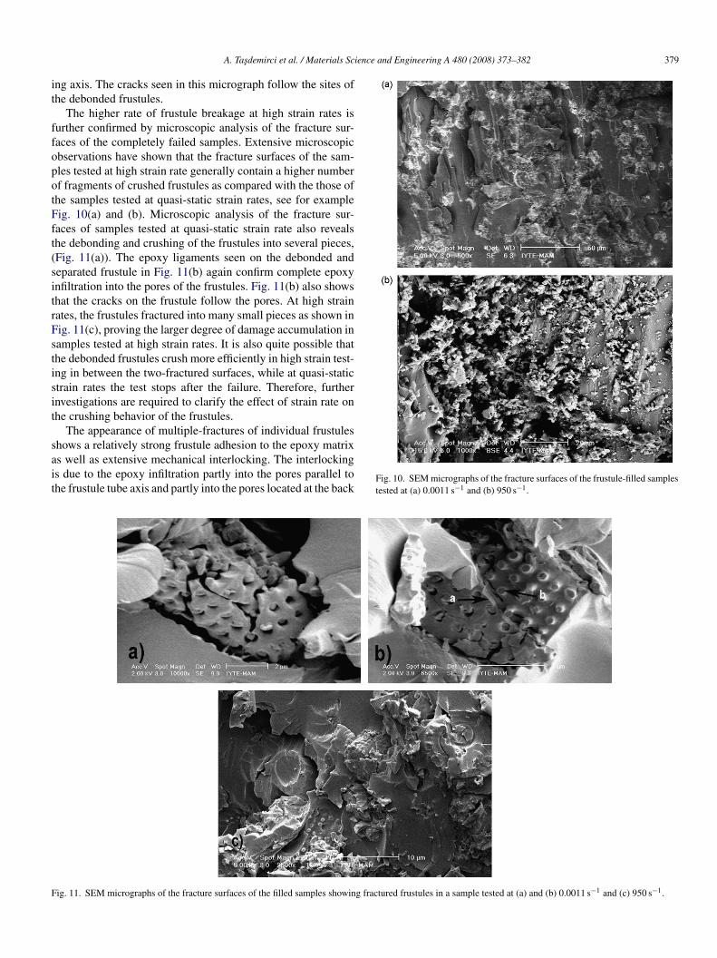
The higher rate of frustule breakage at high strain rates isurther confirmed by microscopic analysis of the fracture sur-aces of the completely failed samples. Extensive microscopicbservations have shown that the fracture surfaces of the sam-les tested at high strain rate generally contain a higher numberf fragments of crushed frustules as compared with the those ofhe samples tested at quasi-static strain rates, see for exampleig. 10(a) and (b). Microscopic analysis of the fracture sur-aces of samples tested at quasi-static strain rate also revealshe debonding and crushing of the frustules into several pieces,Fig. 11(a)). The epoxy ligaments seen on the debonded andeparated frustule in Fig. 11(b) again confirm complete epoxynfiltration into the pores of the frustules. Fig. 11(b) also showshat the cracks on the frustule follow the pores. At high strainates, the frustules fractured into many small pieces as shown inig. 11(c), proving the larger degree of damage accumulation inamples tested at high strain rates. It is also quite possible thathe debonded frustules crush more efficiently in high strain test-ng in between the two-fractured surfaces, while at quasi-statictrain rates the test stops after the failure. Therefore, furthernvestigations are required to clarify the effect of strain rate onhe crushing behavior of the frustules.
The appearance of multiple-fractures of individual frustules
hows a relatively strong frustule adhesion to the epoxy matrixs well as extensive mechanical interlocking. The interlockings due to the epoxy infiltration partly into the pores parallel tohe frustule tube axis and partly into the pores located at the backFig. 10. SEM micrographs of the fracture surfaces of the frustule-filled samplestested at (a) 0.0011 s−1 and (b) 950 s−1.
ig. 11. SEM micrographs of the fracture surfaces of the filled samples showing fractured frustules in a sample tested at (a) and (b) 0.0011 s−1 and (c) 950 s−1.
380 A. Tasdemirci et al. / Materials Science and Engineering A 480 (2008) 373–382
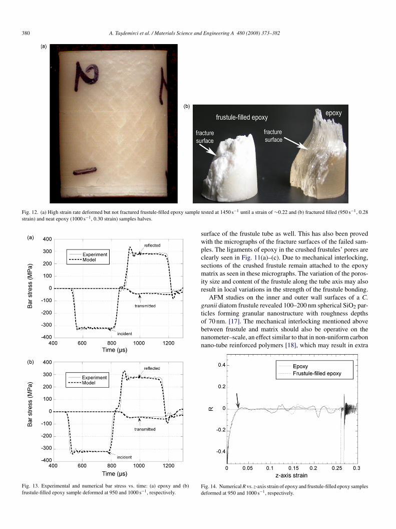
Fig. 12. (a) High strain rate deformed but not fractured frustule-filled epoxy samplestrain) and neat epoxy (1000 s−1, 0.30 strain) samples halves.
Fig. 13. Experimental and numerical bar stress vs. time: (a) epoxy and (b)frustule-filled epoxy sample deformed at 950 and 1000 s−1, respectively.
swpcsmir
gtobnn
Fd
tested at 1450 s−1 until a strain of ∼0.22 and (b) fractured filled (950 s−1, 0.28
urface of the frustule tube as well. This has also been provedith the micrographs of the fracture surfaces of the failed sam-les. The ligaments of epoxy in the crushed frustules’ pores arelearly seen in Fig. 11(a)–(c). Due to mechanical interlocking,ections of the crushed frustule remain attached to the epoxyatrix as seen in these micrographs. The variation of the poros-
ty size and content of the frustule along the tube axis may alsoesult in local variations in the strength of the frustule bonding.
AFM studies on the inner and outer wall surfaces of a C.ranii diatom frustule revealed 100–200 nm spherical SiO2 par-icles forming granular nanostructure with roughness depths
f 70 nm. [17]. The mechanical interlocking mentioned aboveetween frustule and matrix should also be operative on theanometer–scale, an effect similar to that in non-uniform carbonano-tube reinforced polymers [18], which may result in extraig. 14. Numerical R vs. z-axis strain of epoxy and frustule-filled epoxy sampleseformed at 950 and 1000 s−1, respectively.
ience
eirceta
pn(
pnlasat
A. Tasdemirci et al. / Materials Sc
nergy being expended to deform the matrix. The mechanicalnterlocking at the micro and/or nano-scale partly explains theelatively high fracture strains of the frustule-filled epoxy underompressive loading. The presumed mechanical interlocking isxpected to become much more evident under tensile forces;herefore, tensile properties of the frustule-filled epoxy samplesre being investigated in another parallel study.
Microscopic analysis on the deformed but not separated sam-les has shown evidence of shear band formation in filled andeat epoxy samples at both quasi-static and high strain ratesFig. 12(a)). These bands eventually led to fracture in the sam-
p
fc
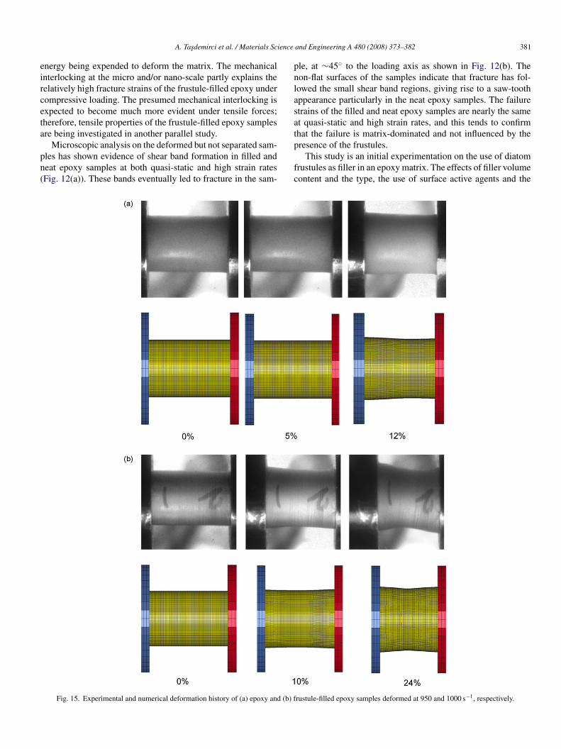
Fig. 15. Experimental and numerical deformation history of (a) epoxy and (b) f
and Engineering A 480 (2008) 373–382 381
le, at ∼45◦ to the loading axis as shown in Fig. 12(b). Theon-flat surfaces of the samples indicate that fracture has fol-owed the small shear band regions, giving rise to a saw-toothppearance particularly in the neat epoxy samples. The failuretrains of the filled and neat epoxy samples are nearly the samet quasi-static and high strain rates, and this tends to confirmhat the failure is matrix-dominated and not influenced by the
resence of the frustules.This study is an initial experimentation on the use of diatomrustules as filler in an epoxy matrix. The effects of filler volumeontent and the type, the use of surface active agents and the
rustule-filled epoxy samples deformed at 950 and 1000 s−1, respectively.

3 e and
tfngryaaepbrvc
3
turstbttvTmd
iwwp(ltteriseifiio
4
(
(ietngtftstowtsrsdfiom
R
[
[
[
[
[
[
82 A. Tasdemirci et al. / Materials Scienc
ype of matrix resin should be further investigated in order toully assess the potential use as filler in polymers. It is furtheroted that the use of diatom frustules as filler in polymers mayive additional functionalities, which include improved wearesistance and fire retardant properties in addition to increasedield strength and modulus. The use of surface couplinggents may further increase the bonding between frustulend polymer. Further experiments are certainly needed toxplore the mechanical and functional properties of these filledolymers. As stated previously the diatom frustule can easilye converted into MgO and TiO2 using solid–gas displacementeactions. Therefore, various types of filling materials witharying shapes and sizes can also be prepared using relativelyheap diatom frustules of various types.
.2. Modeling
Fig. 13(a) and (b) compares experimental results from SHPBests with the corresponding numerical calculations. These fig-res present the stresses in the bars resulting from the incident,eflected and transmitted waves as function of time for an epoxyample tested at 1000 s−1 and for a frustule-filled epoxy sampleested at 950 s−1. Despite the small differences in stress valuesetween experiment and model particularly at the beginning ofhe reflected wave and in the later part of the transmitted stresses,he shape of the model stress–time curve and the maximum stressalues show excellent agreement with those of the experiments.his indicates that the model is indeed accurately capturing theechanical property response of the samples to high strain rate
eformation.The numerical contact force history at the specimen–bar
nterfaces is used to calculate the dimensionless number, R,hich indicates the deviation from homogeneous stress stateithin the sample and is shown in Fig. 14. The R-values areresented as a function of the longitudinal strain in the samplez-strain) and are an average strain calculated along the specimenength. The numerical prediction shows that during the SHPBesting of both materials, the value of R is quite large duringhe initial phase of loading in the elastic portion; however, Rxponentially decreases to 0 and varies between ±0.05 for theest of the loading period after about 3% strain. This numer-cal result corresponds closely with the experimentally foundtress equilibrium based on the “one-wave” and “two-wave”quations mentioned above. Fig. 15(a) and (b) shows the exper-mental and numerical deformation sequences of the epoxy andrustule-filled epoxy sample at various strains. The similaritiesn the deformed shape of the samples between model and exper-ments shown in Fig. 15(a) and (b) further confirm the validityf the model and model parameters used.
. Conclusions
In this study quasi-static (0.0011 s−1) and high strain rate950–1550 s−1) compression behavior of a diatom frustule-filled
[
[[
Engineering A 480 (2008) 373–382
15 wt%) epoxy were investigated experimentally and numer-cally. For comparison, the compression behavior of the neatpoxy was also determined. The frustule tube axis distribu-ion was found to be approximately planar random in a planeormal to the thickness of the epoxy plate molded in a rectan-ular steel die. The compression test was performed parallel tohe planar random plane. Result has shown that 15% diatomrustule filling increases both modulus and yield strength ofhe epoxy matrix at quasi-static and high strain rates withoutignificantly reducing the failure strain. Microscopic observa-ions on the fracture surfaces and the mounted cross-sectionsf deformed samples have shown that the failure mechanismsere debonding of the frustule–epoxy interface and the frac-
ure of the frustules. The model results have confirmed thetress equilibrium attainment in the sample following the elasticegion and showed excellent agreement with the experimentaltress–time response and deformation sequence of the samplesuring high strain rate testing in SHPB. These results con-rm that significant benefits may be anticipated from the usef diatom frustules as reinforcements and fillers in polymericaterials.
eferences
[1] F.E. Round, R.M. Crawford, D.G. Mann, The Diatoms. Biology and Mor-phology of the Genera, Cambridge University Press, Cambridge, 1990.
[2] D. Werner, The Biology of Diatoms, University of California Press, Berke-ley, CA, 1977.
[3] C.S. Gaddis, K.H. Sandhage, J. Mater. Res. 19 (2004) 2541–2545.[4] J. Zhao, C.S. Gaddis, Y. Cai, K.H. Sandhage, J. Mater. Res. 20 (2005)
282–287.[5] D. Losic, J.G. Mitchell, N.H. Voelcker, Chem. Commun. (2005)
4905–4907.[6] K.H. Sandhage, R.L. Snyder, G. Ahmad, S.M. Allan, Y. Cai, M.B. Dicker-
son, C.S. Gaddis, M.S. Haluska, S. Shian, M.R. Weatherspoon, R.A. Rapp,R.R. Unocic, F.M. Zalar, Y. Zhang, M. Hildebrand, B.P. Palenik, Int. J.Appl. Ceram. Technol. 2 (2005) 317–326.
[7] K.M. Wee, T.N. Rogers, B.S. Altan, S.A. Hackney, C. Hamm, J. Nanosci.Nanotechnol. 5 (2005) 88–91.
[8] E.G. Vrieling, T.P.M. Beelen, R.A. van Santen, W.W.C. Gieskes, J. Biotech-nol. 70 (1999) 39–51.
[9] R. Goren, T. Baykara, M. Marsoglu, Br. Ceram. Trans. 101 (2002) 177–181.
10] C.E. Hamm, R. Merkel, O. Springer, P. Jurkojc, C. Maier, K. Prechtel, V.Smetacek, Nature 421 (2003) 841–843.
11] N. Almqvist, Y. Delamo, B.L. Smith, N.H. Thomson, A. Barthold-son, R. Lal, M. Brezezinski, P.K. Hansma, J. Microscopy 202 (2001)518–531.
12] S.A. Crawford, M.J. Higgins, P. Mulvaney, R. Wetherbee, J. Phycol. 37(2001) 543–554.
13] Composite structure design guide, 1997–98, Composite armored vehicleprogram, United Defense L.P.
14] A. Tasdemirci, I.W. Hall, B.A. Gama, M. Guden, J. Comp. Mater. 38 (2004)995–1009.
15] G. Ravichandran, G. Subhash, J. Am. Ceram. Soc. 77 (1994) 263–267.
16] LSTC, LS-DYNA keyword user’s manual. Livermore Software TechnologyCorporation. 2005.17] F. Noll, M. Sumper, N. Hampp, Nano Lett. 2 (2002) 91–95.18] L. Liao, Y. Ren, T. Xiao, in: Y.W. Mai, Z.Z. Yu (Eds.), Polymer Nanocom-
posites, Woodhead Publishing Limited, Cambridge, 2006, pp. 330–356.