diaphragm–liquid pump nf 10 - knf.com · knf flodos ag ba_nf10_en_05_069219 operating and...
TRANSCRIPT

KNF Flodos BA_NF10_EN_05_069219
Operating and Installation Manual keep for future reference!
DIAPHRAGM LIQUID PUMP
NF 10
Operating Instructions
Read and observe these oper-ating instructions! An additional letter before the NF model code is a country-specific designation, with no technical relevance
Contents page
1. About this document ................................................................. 2 2. Use ........................................................................................... 3 3. Safety ....................................................................................... 5 4. Technical Data.......................................................................... 7 5. Assembly and function ........................................................... 10 6. Installation and connection ..................................................... 11 7. Operation ................................................................................ 15 8. Servicing ................................................................................. 18 9. Troubleshooting ...................................................................... 20 10. Spare parts ............................................................................. 22 11. Decontamination declaration .................................................. 23
KNF Flodos AG Wassermatte 2 6210 Sursee, Schweiz
Tel +41 (0)41 925 00 25 Fax +41 (0)41 925 00 35
www.knf-flodos.ch [email protected]
NF 10 KP .51 DC 12V
DC / DCB / E
.51 / - [Section. 2]
KP / KT / KV / TT / TV [Section. 4]
NF / JNF
Supply voltage [Section 4]
10
- / PMLxxxx / PLxxxx [Section. 1)
Diaphragm–Liquid pump NF 10 About this document
KNF Flodos AG BA_NF10_EN_05_069219
Operating and Installation Manual 2
1. About this document
1.1. Using the operating instructions
The operating instructions are part of the pump.
Pass on the operating instructions to the next owner.
Customer-specific project pumps (pump models which begin with
"PL" or "PML") may differ from the operating instructions.
For project pumps, also observe the agreed upon specifica-
tions.
1.2. Symbols and markings
Warning
WARNUNG
A danger warning is located here. Possible consequences of a failure to observe the
warning are specified here. The signal word, e.g.
Warning, indicates the danger level. Measures for avoiding the danger and its conse-
quences are specified here.
Danger levels
Signal word Meaning Consequences if not observed
DANGER warns of immedi-ate danger
Death or serious injuries and/or serious damage are the conse-quence.
WARNING warns of possible danger
Death or serious injuries and/or serious damage are possible.
CAUTION warns of a possi-bly dangerous situation
Minor injuries or damage are possible.
Tab. 1
Other information and symbols
An activity to be carried out (a step) is specified here.
1. The first step of an activity to be carried out is specified here.
Additional, consecutively numbered steps follow.
This symbol refers to important information.
Project pumps

Diaphragm–Liquid pump NF 10 Use
KNF Flodos AG BA_NF10_EN_05_069219
Operating and Installation Manual 3
2. Use
2.1. Proper use
The pumps are exclusively intended for transferring liquids and
gases.
Owner's responsibility
Only install and operate the pumps under the operating parameters
and conditions described in Chapter 4, Technical data.
The pump may be operated only when fully assembled.
Before using a medium, check whether the medium can be trans-
ferred danger-free in the specific application case.
Before using a medium, check the compatibility of the materials of
the pump head, diaphragm and valves with the medium
The temperature of the media must lie within the allowed limits
stated in chapter 4.
The media should not contain particles as these can prevent the
pump from working correctly. If this can not be guaranteed a filter
(approx. 50 µm) must be used in front of the pump.
The .51 versions of our diaphragm liquid pump range have been
certified by NSF according to the standard NSF/ANSI 169 and can
therefore be used, without any limitations, with foodstuffs.
All materials used for the wetted parts have been through a series
of toxilogical tests. In order to ensure that the food grade quality is
maintained NSF will carry out a yearly audit checking all of the
production processes.
Only the pumps marked with “.51” have been certified by NSF and
contain materials which have a FDA certificate of conformity.
To see the operating conditions see 4.2
NSF: National Sanitary Foundation
FDA: Food and Drug Administration
ANSI: American National Standard Institute
*on request it is possible to deliver pumps with customer specific
material combinations.
Operating parameters and
conditions
Requirements for
transferred medium
.51*-Version – Version with
Food grade approval
Diaphragm–Liquid pump NF 10 Use
KNF Flodos AG BA_NF10_EN_05_069219
Operating and Installation Manual 4
All certified pumps are clearly marked with “51” in the pump
description on the type sticker along with the NSF-logo. If none
or only one of these things are not present then the pump is
not certified.
Because the requirements of how the pump needs to cleaned
are dependant on the application and KNF can not influence
this the responsibility lies with the user. The regulations
NSF/ANSI 169 regulate OEM products and does not mention
how the cleaning should be made.
All wetted parts can be replaced as spare parts without losing
the certification. Component parts can not be traded as certi-
fied parts. Only original parts / assemblies from KNF may be
used.
2.2. Improper use
The pumps may not be operated in an explosive atmosphere.
The pump may not be exposed to a positive pressure on the inlet
side.
For special modifications outside the standard technical specifica-
tions please contact a KNF pump specialist.

Diaphragm–Liquid pump NF 10 Safety
KNF Flodos AG BA_NF10_EN_05_069219
Operating and Installation Manual 5
3. Safety
Note the safety precautions in sections 6. Installation and
connection, and 7. Operation.
The pumps are built according to the generally recognized rules of
technology and in accordance with the occupational safety and
accident prevention regulations. Nevertheless, dangers can result
during their use which leads to injuries to the user or others, or to
damage to the pump or other property.
Only use the pumps in proper technical condition and in accord-
ance with their intended use in a safety and danger-conscious
manner while observing the operating instructions.
Make sure that only trained and instructed personnel or specially
trained personnel work on the pumps. This especially applies to
assembly, connection and servicing work.
Make sure that the personnel has read and understood the operat-
ing instructions, and in particular the "Safety" chapter.
Observe the accident prevention and safety regulations when
performing any work on the pump and during operation.
When transferring dangerous media, observe the safety regula-
tions when handling these media.
All warning stickers and pump information placed on the pump
should be kept in a readable condition.
Store all replacement parts in a protected manner and dispose of
them properly in accordance with the applicable environmental
protection regulations. Observe the respective national and inter-
national regulations. This especially applies to parts contaminated
with toxic substances.
Dispose of all packaging in an environmentally appropriate
manner. The packaging materials are recyclable.
Ensure that the pump is disposed of in an environmentally
appropriate manner at the end of its useful life. Use appropri-
ate waste collection systems for the disposal of end-of-life
equipment. Used pumps contain valuable recyclable materials.
Personnel
Working in a safety-
conscious manner
Handling dangerous media
Notes
Environmental protection
Disposal

Diaphragm–Liquid pump NF 10 Safety
KNF Flodos AG BA_NF10_EN_05_069219
Operating and Installation Manual 6
The pumps are in accordance with the requirements of the guide-
lines 2011/65/EU (ROHS2)
The diaphragm liquid pumps conform with the EU safety require-
ments and guidelines for the Electro magnetic interference
2004/108/EG
According to the machinery directive 2006/42/EG pumps are
incomplete machines and are thus to be considered as not ready
for use. The use of an incomplete machine is forbidden until it has
been proven that the machine in which the incomplete machine is
integrated meets the requirements of the machinery directive
2006/42/EG.
The Basic requirements of the machinery directive 2006/42/EG
according to appendix I (general principles) are to be used and
maintained.
The following harmonised standards are fulfilled:
NF 10 DC
▪ EN 55022
▪ EN 55011
NF 10 DCB
▪ EN 61000-6-2
▪ EN 61000-6-3 (incl.: EN 55022 / EN 55011)
NF 10 E
▪ EN 55014-1
Only have repairs to the pumps carried out by the KNF Customer
Service responsible.
EU directives/standards
Customer service and
repairs

Diaphragm–Liquid pump NF 10 Technical Data
KNF Flodos AG BA_NF10_EN_05_069219
Operating and Installation Manual 7
4. Technical Data
Pump materials
The pump type KP stands for:
Head component Material1)
Pump head * PP
Valves / seals EPDM
Diaphragm EPDM
Resonating diaphragm EPDM
Tab. 2 1) according DIN ISO 1629 and 1043.1
The pump type KT stands for:
Head component Material1)
Pump head * PP
Valves / seals FFKM
Diaphragm PTFE
Resonating diaphragm FFKM
Tab. 3 1) according DIN ISO 1629 and 1043.1
The pump type KV stands for:
Head component Material1)
Pump head * PP
Valves / seals FKM
Diaphragm FKM
Resonating diaphragm FKM
Tab. 4 1) according DIN ISO 1629 and 1043.1
The pump type TT stands for:
Head component Material1)
Pump head * PVDF
Valves / seals FFKM
Diaphragm PTFE
Resonating diaphragm FFKM
Tab. 5 1) according DIN ISO 1629 and 1043.1
The pump type TV stands for:
Head component Material1)
Pump head * PVDF
Valves / seals FKM
Diaphragm FKM
Resonating diaphragm FKM
Tab. 6 1) according DIN ISO 1629 and 1043.1
* Pump head (Fig.1): contains connection plate and intermediate plate

Diaphragm–Liquid pump NF 10 Technical Data
KNF Flodos AG BA_NF10_EN_05_069219
Operating and Installation Manual 8
Hydraulic ratings
Parameter Value
Flow rate [ml/min] 1), 2) 100
Max. allowed pressure NF 10 [bar] 1
Suction height [mWg] 3
Tab. 7
1) Measured with water at 20°C / at atmospheric pressure
2) Flow rates may vary from the values shown according to fluid viscosity,
pump head material and hoses / hose connectors used. Calibration with
the pumped medium is required.
Hydraulic connections
Parameter Value
Recommended tube size ID [mm] 4
Tab. 8
Specifications NF 10 DC
Motor voltages 12V 24V
Power [W] 3.7 3.4
Max. current at max load [A] 0.28 0.13
Max. motor current [A] 0.31 0.14
Lead size [-] AWG22
Protection class [-] IP30
Weight1) [g] 60
Tab. 9
Specifications NF 10 DCB
Motor voltages 12V 24V
Power [W] 1.7 1.7
Max. current at max load [A] 0.14 0.07
Max. motor current [A] 0.45 0.45
Power supply range [V] 10…28 10…28
Lead size [-] AWG28
Protection class [-] IP40
Weight1) [g] 56
Tab. 10
1) The weight can differ slightly from the stated value depending on the
version

Diaphragm–Liquid pump NF 10 Technical Data
KNF Flodos AG BA_NF10_EN_05_069219
Operating and Installation Manual 9
Specifications NF 10 E
Motor voltage 230V/50Hz 115V/60Hz
Power [W] 18.5 19.6
Max. current at max. load [A] 0.17 0.37
Max. motor current [A] 0.19 0.41
Power supply range [V] 230V ±10% 115V ±10%
Protection class [-] IP00
Weight1) [g] 385
Tab. 11
Motor voltage 100V/50-60Hz
50Hz 60Hz
Power [W] 18 13.3
Max. current at max. load [A] 0.40 0.28
Max. motor current [A] 0.44 0.31
Power supply range [V] 100V ±10%
Protection class [-] IP00
Weight1) [g] 385
Tab. 12
1) The weight can differ slightly from the stated value depending on the
version
Electrostatic sensitive components (ESD)
Various parameters
Parameter Value
Ambient temperature range (°C) + 5 to + 40
Media temperature range (°C) + 5 to + 80
Allowed kinematic viscosity of the media [cSt]
≤ 150
Tab. 13
Diaphragm–Liquid pump NF 10 Assembly and function
KNF Flodos AG BA_NF10_EN_05_069219
Operating and Installation Manual 10
5. Assembly and function
Assembly
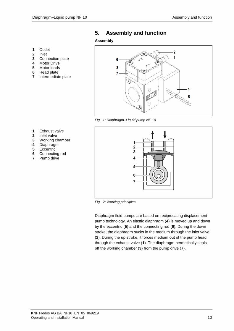
1 Outlet 2 Inlet 3 Connection plate 4 Motor Drive 5 Motor leads 6 Head plate 7 Intermediate plate
Fig. 1: Diaphragm–Liquid pump NF 10
1 Exhaust valve 2 Inlet valve 3 Working chamber 4 Diaphragm 5 Eccentric 6 Connecting rod 7 Pump drive
Fig. 2: Working principles
Diaphragm fluid pumps are based on reciprocating displacement
pump technology. An elastic diaphragm (4) is moved up and down
by the eccentric (5) and the connecting rod (6). During the down
stroke, the diaphragm sucks in the medium through the inlet valve
(2). During the up stroke, it forces medium out of the pump head
through the exhaust valve (1). The diaphragm hermetically seals
off the working chamber (3) from the pump drive (7).

Diaphragm–Liquid pump NF 10 Installation and connection
KNF Flodos AG BA_NF10_EN_05_069219
Operating and Installation Manual 11
6. Installation and connection
Only install and operate the pumps under the operating parameters
and conditions described in Chapter 4, Technical data. Observe
the safety precautions (see Chapter 3).
6.1. Installation
Before installation, store the pump at the installation location to
bring it up to ambient temperature.
Mounting dimensions (see Fig. 3 to 7)
Fig. 3: Mounting dimensions NF 10 DC
Fig. 4: Mounting dimensions NF 10 DCB
Mounting dimensions

Diaphragm–Liquid pump NF 10 Installation and connection
KNF Flodos AG BA_NF10_EN_05_069219
Operating and Installation Manual 12
Fig. 5: Mounting dimensions NF 10 E
Diaphragm–Liquid pump NF 10 Installation and connection
KNF Flodos AG BA_NF10_EN_05_069219
Operating and Installation Manual 13
Make sure that the installation location is dry and the pump is
protected against rain, splash, hose and drip water.
Protect the pump from dust.
Protect the pump from vibrations and jolts.
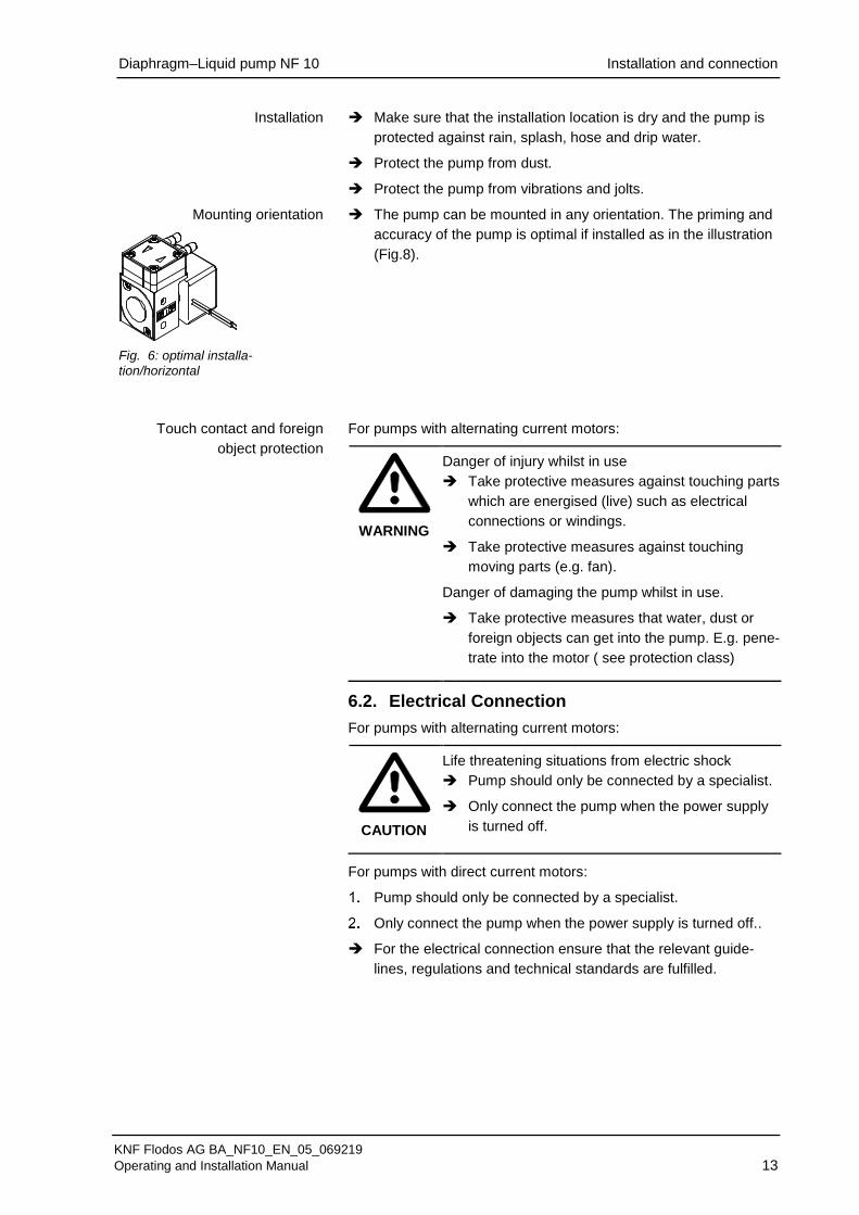
The pump can be mounted in any orientation. The priming and
accuracy of the pump is optimal if installed as in the illustration
(Fig.8).
For pumps with alternating current motors:
WARNING
Danger of injury whilst in use
Take protective measures against touching parts
which are energised (live) such as electrical
connections or windings.
Take protective measures against touching
moving parts (e.g. fan).
Danger of damaging the pump whilst in use.
Take protective measures that water, dust or
foreign objects can get into the pump. E.g. pene-
trate into the motor ( see protection class)
6.2. Electrical Connection
For pumps with alternating current motors:
CAUTION
Life threatening situations from electric shock
Pump should only be connected by a specialist.
Only connect the pump when the power supply
is turned off.
For pumps with direct current motors:
Pump should only be connected by a specialist.
Only connect the pump when the power supply is turned off..
For the electrical connection ensure that the relevant guide-
lines, regulations and technical standards are fulfilled.
Installation
Mounting orientation
Fig. 6: optimal installa-
tion/horizontal
Touch contact and foreign
object protection
Diaphragm–Liquid pump NF 10 Installation and connection
KNF Flodos AG BA_NF10_EN_05_069219
Operating and Installation Manual 14
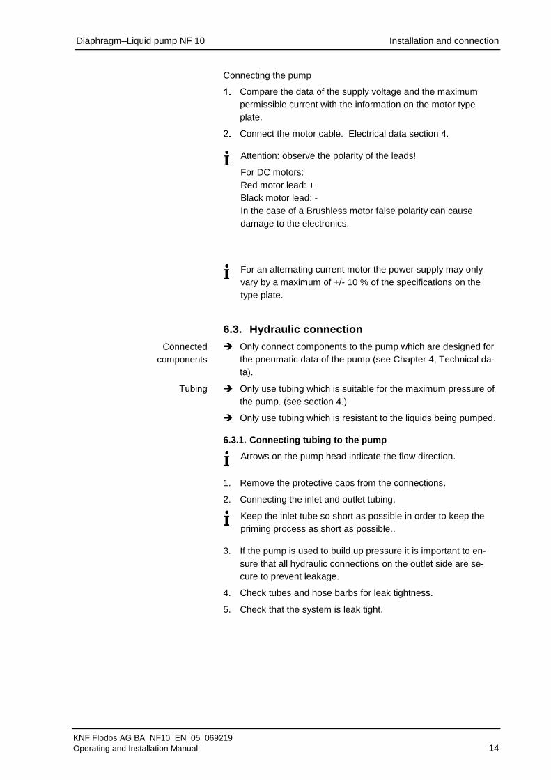
Connecting the pump
Compare the data of the supply voltage and the maximum
permissible current with the information on the motor type
plate.
Connect the motor cable. Electrical data section 4.
Attention: observe the polarity of the leads!
For DC motors:
Red motor lead: +
Black motor lead: -
In the case of a Brushless motor false polarity can cause
damage to the electronics.
For an alternating current motor the power supply may only
vary by a maximum of +/- 10 % of the specifications on the
type plate.
6.3. Hydraulic connection
Only connect components to the pump which are designed for
the pneumatic data of the pump (see Chapter 4, Technical da-
ta).
Only use tubing which is suitable for the maximum pressure of
the pump. (see section 4.)
Only use tubing which is resistant to the liquids being pumped.
6.3.1. Connecting tubing to the pump
Arrows on the pump head indicate the flow direction.
1. Remove the protective caps from the connections.
2. Connecting the inlet and outlet tubing.
Keep the inlet tube so short as possible in order to keep the
priming process as short as possible..
3. If the pump is used to build up pressure it is important to en-
sure that all hydraulic connections on the outlet side are se-
cure to prevent leakage.
4. Check tubes and hose barbs for leak tightness.
5. Check that the system is leak tight.
Connected
components
Tubing

Diaphragm–Liquid pump NF 10 Operation
KNF Flodos AG BA_NF10_EN_05_069219
Operating and Installation Manual 15
7. Operation
The pumps should only be used under normal operating pa-
rameters / conditions which are described in section 4 – tech-
nical data.
Ensure that the pumps are being used correctly (see section
2.1).
Improper use of the pump must be avoided (see section 2.2).
Observe the safety notes (see chapter 3).
The pumps are components which have to be integrated into a
machine. Before they are put into operation it is important to
ensure that the machine / equipment complies with the appro-
priate regulations.
CAUTION
Danger of burning
The motor heats up Don’t touch the motor
Don’t let the motor come in contact with flamma-
ble materials
Excessive pressures and the dangers thus caused can be
prevented by using a bypass system with a pressure relief
valve between the pressure and suction side of the pump. For
further information please contact a KNF specialist (Telephone
number: see front page).
If the pump stops running release the pressure in the system to
that atmospheric conditions are created.
For pumps with a thermal switch:
WARNING
Physical injury and damage to the pump due to
automatic start.
If in the case of excessive temperatures the thermal
switch will stop the motor. Once cooled down the
motor will automatically start operation again.
Ensure that no dangerous situation can thereby
arise.
Switching the pump on and off
The motor speed and thus the flow rate can be adjusted / con-
trolled
For more details see section 4 technical data.
Pump standstill
Adjusting and controlling the
motor speed

Diaphragm–Liquid pump NF 10 Operation
KNF Flodos AG BA_NF10_EN_05_069219
Operating and Installation Manual 16
Duty cycle / impulse operation
KNF pumps are designed for continual use
Short start and stop cycles can change the lifetime of the brushed
motors.
If the pump is operated with short cycles in your application
please contact a KNF pump specialist for further information
(Telephone number: see front page).
Turning the pump on
In order to guarantee that the pump can start every time it is
advisable to reduce the back pressure down to an acceptable
level. This is also the case if there is a short power cut.
For more specific information contact the KNF specialist (Tele-
phone number: see front page).
Turning the pump off
KNF recommends that after pumping aggressive liquids the
pump should be rinsed thoroughly. (see section 8.2.1), as this
will help to lengthen the lifetime.
Ensure that there are atmospheric pressure conditions in the
system (release the hydraulic pressure).
Impulse operation

Diaphragm–Liquid pump NF 10 Operation
KNF Flodos AG BA_NF10_EN_05_069219
Operating and Installation Manual 17
Flow rate NF 10
Fig. 7: Flow rate of the pump NF 10 DC
Fig. 8: Flow rate of the pumps NF 10 E and NF 10 DCB
Suction Head [mWg] Pressure Head [mWg]F
low
Rate
[l/m
in]
NF 10-DC
0.35
0.30
0.25
0.20
0.15
0.10
0.05
0
Suction Head [mWg] Pressure Head [mWg]
Flo
wR
ate
[l/m
in]
NF 11-DC
NF 10-E
NF 10-DCB
0.35
0.30
0.25
0.20
0.15
0.10
0.05
0
Diaphragm–Liquid pump NF 10 Servicing
KNF Flodos AG BA_NF10_EN_05_069219
Operating and Installation Manual 18
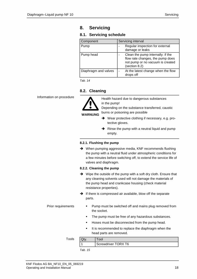
8. Servicing
8.1. Servicing schedule
Component Servicing interval
Pump - Regular inspection for external damage or leaks
Pump head - Clean the pump internally: if the flow rate changes, the pump does not pump or no vacuum is created (section 8.2)
Diaphragm and valves - At the latest change when the flow drops off
Tab. 14
8.2. Cleaning
WARNUNG
Health hazard due to dangerous substances
in the pump!
Depending on the substance transferred, caustic
burns or poisoning are possible
Wear protective clothing if necessary, e.g. pro-
tective gloves.
Rinse the pump with a neutral liquid and pump
empty.
8.2.1. Flushing the pump
When pumping aggressive media, KNF recommends flushing
the pump with a neutral fluid under atmospheric conditions for
a few minutes before switching off, to extend the service life of
valves and diaphragm.
8.2.2. Cleaning the pump
Wipe the outside of the pump with a soft dry cloth. Ensure that
any cleaning solvents used will not damage the materials of
the pump head and crankcase housing (check material
resistance properties).
If there is compressed air available, blow off the separate
parts.
▪ Pump must be switched off and mains plug removed from
the socket.
▪ The pump must be free of any hazardous substances.
▪ Hoses must be disconnected from the pump head.
▪ It is recommended to replace the diaphragm when the
head parts are removed.
Qty. Tool
1 Screwdriver TORX T6
Tab. 15
Information on procedure
Prior requirements
Tools

Diaphragm–Liquid pump NF 10 Servicing
KNF Flodos AG BA_NF10_EN_05_069219
Operating and Installation Manual 19
Disassembling the pump head
1. Undo the 4 head screws (1) using a Torx T6 screwdriver and
remove the head plate (2).
2. Remove the resonating diaphragm (3) from the connection
plate (4).
Removing valves and seals
3. Remove the connection plate (4) from the intermediate plate
(6).
4. Take out the valves (5) from the intermediate plate (6).
5. Grip the diaphragm (7) and turn it anti-clockwise. Ensure that
none of the spacers (8) don’t fall into the housing.
It is recommended to replace the diaphragm (7).
Clean the parts
6. Using a cloth clean the Head plate (2), connecting plate (4),
intermediate plate (6), valve plate (5) and diaphragm (7) and
blow compressed air over them.
Replace the diaphragm
7. Place all of the spacers (8) back onto the diaphragm thread.
8. Screw the diaphragm (7) securely back into the con-rod. Make
sure that no spacers (8) fall into the housing.
9. By lightly pressing on the diaphragm push the ridge on the
underside of the diaphragm into the groove of the housing..
Install the valves
10. Place the „dust free“ valve plate(5) into the intermediate plate
(6).
Assemble the pump head
11. Place the resonating diaphragm (3) in the top of the connection
plate (4) and cover with the head plate (2).
12. The visible lines down the side of the pump must be inline on
the intermediate and connection plate.
13. The head plate (2) must be positioned so that the arrows
coincide with the hydraulic connections on the connection plate
(4).
14. Push the four head screws (1) into the head holes.
15. Place the pump head onto the pump housing and tighten the
head screw diagonally.
16. Connect the pump up with the inlet and outlet tubes.
8.3. Replace the diaphragm and valves
The same procedure is to followed as in section 8.2 cleaning. But
instead of just cleaning the diaphragm (7), resonating diaphragm
(3) and valves (5) these must be replaced with new parts.
Fig. 9
1 Head screws 2 Head plate 3 Resonating diaphragm 4 Connection plate 5 Valve plate 6 Intermediate plate 7 Diaphragm 8 Spacer
Diaphragm–Liquid pump NF 10 Troubleshooting
KNF Flodos AG BA_NF10_EN_05_069219
Operating and Installation Manual 20
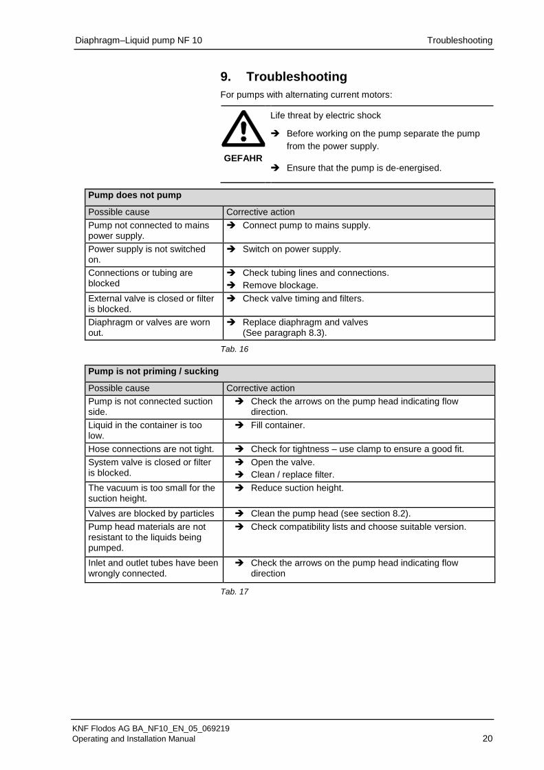
9. Troubleshooting
For pumps with alternating current motors:
GEFAHR
Life threat by electric shock Before working on the pump separate the pump
from the power supply.
Ensure that the pump is de-energised.
Pump does not pump
Possible cause Corrective action
Pump not connected to mains power supply.
Connect pump to mains supply.
Power supply is not switched on.
Switch on power supply.
Connections or tubing are blocked
Check tubing lines and connections.
Remove blockage.
External valve is closed or filter is blocked.
Check valve timing and filters.
Diaphragm or valves are worn out.
Replace diaphragm and valves (See paragraph 8.3).
Tab. 16
Pump is not priming / sucking
Possible cause Corrective action
Pump is not connected suction side.
Check the arrows on the pump head indicating flow direction.
Liquid in the container is too low.
Fill container.
Hose connections are not tight. Check for tightness – use clamp to ensure a good fit.
System valve is closed or filter is blocked.
Open the valve.
Clean / replace filter.
The vacuum is too small for the suction height.
Reduce suction height.
Valves are blocked by particles Clean the pump head (see section 8.2).
Pump head materials are not resistant to the liquids being pumped.
Check compatibility lists and choose suitable version.
Inlet and outlet tubes have been wrongly connected.
Check the arrows on the pump head indicating flow direction
Tab. 17

Diaphragm–Liquid pump NF 10 Troubleshooting
KNF Flodos AG BA_NF10_EN_05_069219
Operating and Installation Manual 21
Flow rate, suction height or pressure is too low
The pump does not achieve the technical performance data stated on the data sheet
Cause Fault remedy
Components in the system such as tubing, valves or filter are causing too much resistance.
Change installation.
Take larger tubes.
Connections are not tight Use another connection or use clamps to ensure a tight fit.
Particles in the pump Use a filter – clean the pump head. (see section 8.2)
Viscosity of the liquid is too high Contact your local KNF company.
Inlet and outlet tubing are connected wrongly.
Check the arrows on the pump head indicating flow direction.
The head parts are not resistant against the media.
Replace the head parts with a compatible variation.
Tab. 18
Fault cannot be rectified
If you are unable to identify any of the above causes, please send
the pump to KNF customer services (See address on last page).
Flush the pump to clear the pump head of any hazardous or
aggressive fluids (see section 8.2.1).
Dismantle the pump.
Clean the pump (see section 8.2.2).
Send the pump, with completed decontamination statement
(see Chapter 11), to KNF customer services, stating the nature
of the pumped medium.

Diaphragm–Liquid pump NF 10 Spare parts
KNF Flodos AG BA_NF10_EN_05_069219
Operating and Installation Manual 22
10. Spare parts
Spare part Order No.
Spares-Kit Assembly sheet 151356
Spare part NF 10 JNF 10_V 151366
Spare part NF 10 JNF 10_P 151367
Spare part NF 10 JNF 10_T 151368
Tab. 19
Diaphragm–Liquid pump NF 10 Decontamination declaration
KNF Flodos AG BA_NF10_EN_05_069219
Operating and Installation Manual 23
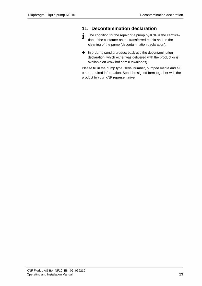
11. Decontamination declaration
The condition for the repair of a pump by KNF is the certifica-
tion of the customer on the transferred media and on the
cleaning of the pump (decontamination declaration).
In order to send a product back use the decontamination
declaration, which either was delivered with the product or is
available on www.knf.com (Downloads).
Please fill in the pump type, serial number, pumped media and all
other required information. Send the signed form together with the
product to your KNF representative.

KNF worldwide
Please find your local KNF partners at: www.knf.com