diaphragm expansion vessels - ghana ib &...
TRANSCRIPT

Refl ex, Refi x
Diaphragm Expansion Vessels
BR_MAG_rz_EN_2.indd 2 07.03.13 12:08

2
Reflex has set itself the goal of supporting you with well thought-through solutions. Whatever job you need doing in water supply engineering, why not put your trust in our comprehensive range of products and accompanying tailored services? We will ensure that your decision to opt for Reflex is the right one in every respect – from advice and design to installation and ongoing operation.
Reflex's mission is embodied in the company's slogan: "Thinking solutions". Reflex's strength is to think in terms of solutions. Reflex develops ideas that help you to move forward based on decades of experience, in-depth technical understanding and our intimate knowledge of the industry!
We are only satisfied when you are.
BR_MAG_rz_EN_2.indd 3 07.03.13 12:08

DiaphragmExpansionVessels
PressurizationSystems
Water Make-UpSystems &Water Treatment
Hot Water Storage Tanks & Heat Exchangers
Services
Deaeration Systems & SeparationTechnology
The Reflex
Product Range
33
We make sure that everything fits
Heating, cooling, hot water supply – water is indispensable for so many things in our everyday lives. Reflex looks after the quality of this water with a wide range of products, because this ultimately affects your air conditioning, energy efficiency, reliability, maintenance intervals and service life of your system. Discover with Reflex the many ways of optimizing your supply systems in the long term with minimal effort. Our six product ranges provide high- performance combinations, versatile applications and cost-effective solutions, which we would like to present in this brochure.
This brochure focuses on diaphragm expansion vessels that are capable of maintaining the necessary pressure and compensating for the fluctuations in volume in a vessel with static pressurized cushions of air. Reflex offers you a comprehensive range of products for every application.
We are only satisfied when you are.
Contents
Diaphragm expansion page 4vessels
Reflex for heating, page 6 solar power and coolingwater systems
Networked solutions page 8with Reflex
Refix for drinking water and service water systems page 10
Networked solutions page 12with Reflex
Service provision page 14
Technical data page 16
BR_MAG_rz_EN_2.indd 4 07.03.13 12:08

4
What are diaphragm expansion vessels?
The correct pressure is the prerequisite for the proper operation of heating, solar power and cooling water systems, as well as pressure booster systems. It is essential to maintain water at a stable balance, to compensate for variations in volume at regulated pressure and prevent gas separation and cavitation. Diaphragm expansion vessels offer a simple and intelligent solution here. They also act as ideal expansion vessels or buffer vessels without the need for electrical power, a compressor or pump.
They are very simple to operate. A diaphragm divides the vessel into a water space and a gas space and prevents gas from diffusing into the water. The water space is connected to the external plant by the vessel connection. The static pressurized cushion of air in the gas space is set once in the factory using a fi lling valve. This restricts on average the volume of water accommodated within the vessel to a third of the total volume of the vessel.
Refl ex offers two basic designs of diaphragm expansion vessels:
Diaphragm expansion vessels
Refl ex for closed heating, solar power and cooling water systems
Refi x for potable water and service water systems and special applications, e.g. in brine circuits for heat pumps
BR_MAG_rz_EN_2.indd 5 07.03.13 12:09

Water intake
External system
Water output
5
What are diaphragm expansion vessels?
The pressurized cushion of air supports the water column within the system and is set before a reserve of water is poured into the vessel. When the system heats up, the pressure rises with the result that expansion water flows from the external system into the water space. The pres-surized cushion of air in the gas space is compressed and the pressure rises. When the system cools down, the volume decreases and the pressure falls: The expansion water flows from the water space back into the external system. This releases the pressurized cushion of air in the gas space and lowers the pressure.
The pressurized cushion of air in the gas space is set approximately below the pump's switch-on pressure. When the pressure falls below the switch-on pressure, the pump switches on and pumps water. If consumers remove a relatively small volume of water, the difference in the buffer vessel is stored until the pressurized cushion of air on the switch-off side has compressed and the booster system has switched off. The resulting loss of pressure leads to a fall in volume. When consumers take water, the interim water is taken from the buffer vessel until the pressurized cushion of air has fallen to the switch-on pressure and the booster system switches on again.
Expansion vessels
Expansion vessels have to compensate for the fluctuations in volume between the maximum and minimum temperature and maintain the pressure within a permissible range. Reflex products are used here as expansion vessels to main-tain pressure in heating, solar power and cooling water systems, while Refix products are used as expansion vessels to save potable water in hot water systems.
An example of Reflex in a heating system:
Buffer tanks
Buffer tanks have to intermediately store the difference between the pumped volume flow and the volume flow actually needed. Control tanks are used when you merely want to reduce the switching frequency of a pump. As a rule, the Refix range is used as a buffer tank in booster systems, while Reflex products are used as control tanks in pump-controlled pressurization stations.
An example of Reflex in a booster system:
Consumer
∆V = V1 - V2
V2
Booster system
Filling valve
Pressurized cushion of air in the gas space
Diaphragm
Water space
V1
BR_MAG_rz_EN_2.indd 6 07.03.13 12:09

Refl ex for sealed heating, solar power and cooling water systems
6
The Refl ex product line is broad and varied to create any customer-specifi c solutions required. It can be used within different pressure ranges and nominal volumes, either fl at or cylindrical depending on the application, and with a fi xed diaphragm or a replaceable bladder.
Diaphragm expansion vessels
Refl ex N, NG and G diaphragm expansion vessels
Refl ex N and NG are some of the world's most frequently used small vessels. The fi xed diaphragm has proved itself millions of times over and has shown itself to be extremely wear-resistant, thanks to its evenly-balanced loading. The replaceable bladder in the Refl ex G meets all the requirements for repeated inspections needed with larger vessels.
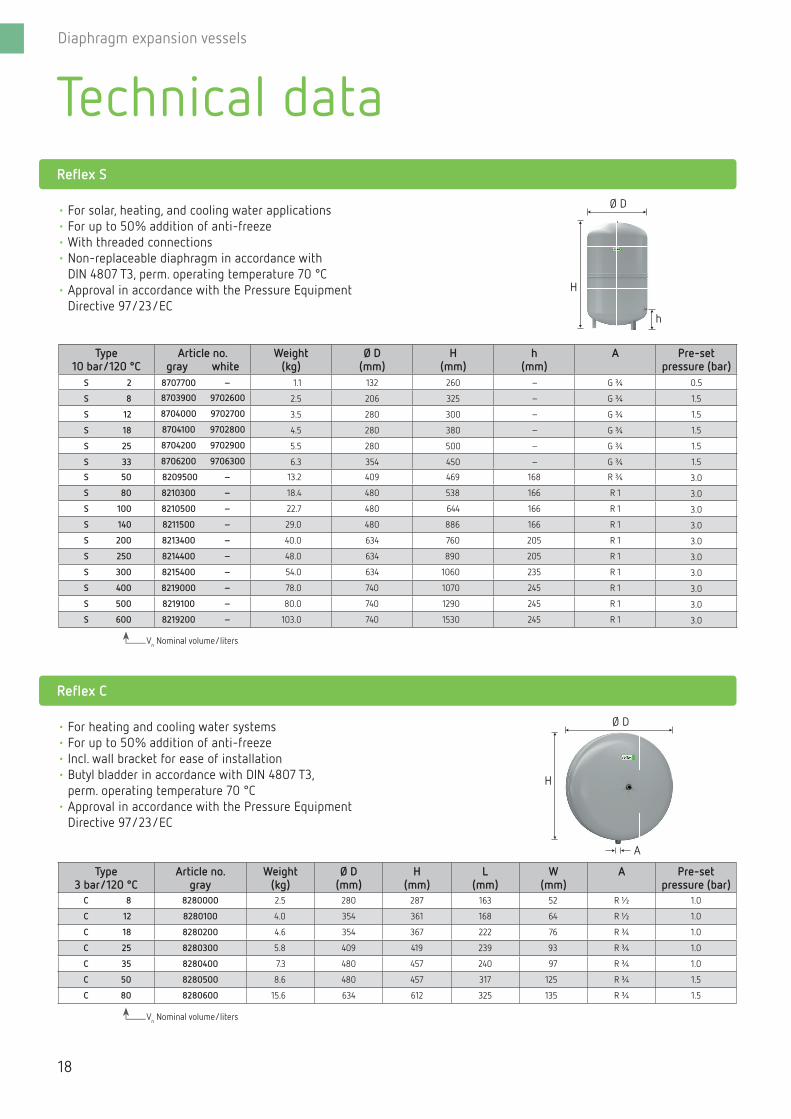
Refl ex S diaphragm expansion vessels
Designed as the specialist expansion vessel for solar systems, the series S has been designed especially for the addition of up to 50% anti-freeze and pressures of up to 10 bar, making it ideal for use with heating and cooling systems.
Nominal volume 2-600 l
Perm. excess operating pressure 10 bar
Perm. operating temperature of vessel/membrane
120 °C/70 °C
Model from S 50 with legs
Color gray, S 8-S 33 also available in white
Nominal volume 8-5000 l
Perm. excess operating pressure 3, 6, 10 barPerm. operating temperature of vessel/membrane 120 °C/70 °C
Model from N/NG 35 with legs
Non-standard models (> 10 bar, > 5,000 l) for Refl ex G on request
Color gray, N 8-N 80 and NG 8-NG 140 also available in white
BR_MAG_rz_EN_2.indd 7 07.03.13 12:10

Refl ex for sealed heating, solar power and cooling water systems
7
Detailed product information can be found on pages 16-19.
Refl ex F diaphragm expansion vessels
The space-saving Refl ex F is the ideal unit for use with every wall-mounted boiler. Refl ex also offers tailored solutions alongside the standard range outlined in the following section.
Refl ex C diaphragm expansion vessels
The further developed, higher-performance Refl ex F incorporates many practical benefi ts: The fl at cylindrical housing with integral hanging bracket allows space- saving, fast wall installation. The bladder is made of butyl. In spite of its large surface area, diffusion between the gas and water spaces is prevented and the pre-set pressure remains stable.
Nominal volume 8–24 l
Perm. excess operating pressure 3 barPerm. operating temperature of vessel/membrane 120 °C/70 °C
Color white
Nominal volume 8-80 l
Perm. excess operating pressure 3 barPerm. operating temperature of vessel/membrane 120 °C/70 °C
Color gray
BR_MAG_rz_EN_2.indd 8 07.03.13 12:10

Networked solutions with Reflex
8
Refl ex expansion tanks for pressure maintenance can also be combined with a range of different accessories to utilize networked solutions with water make-up and degassing, thereby creating fl exibility for commercial and customer-led solutions in the 100 to 1,000 kW range.
Diaphragm expansion vessels
Refl ex N with accessories in a small heating system
Refl ex N units up to 25 liters can be quickly and easily installed with a lock-shield valve and bracket with tightening strap. The Refl ex Fillsoft water softening unit guarantees optimum hardness of fi lling water and make-up water, signifi cantly extending the boiler's service life.
The Fillcontrol Auto version for use with anti-freeze enables the unit to be connected to an open mixing vessel, also enabling the optimum content of anti-freeze to be guaranteed with automatic water make-up.
Refl ex S combined with a Fillcontrol Auto make-up station in a solar power system
The Refl ex S works reliably even in the event of a power outage and maximum solar radiation. When switched in parallel, it is also the ideal system extension in larger systems. A useful addition is the use of a Fillcontrol Auto water make-up system.
An in-line vessel to protect the dia-phragm in the Refl ex S from excess temperatures may be needed, de-pending on the confi guration of the solar system.
Refl ex N with
BR_MAG_rz_EN_2.indd 9 07.03.13 12:11

Networked solutions with Reflex
9
The Fillcontrol Auto can make up wa ter up to 8.5 bar. A system separation vessel permits direct connection to potable water networks. With adequate pressure, it is also possible to make up water using a Fillcontrol.
The Servitec degasses, monitors the Refl ex N with its integral pressure sensor and automatically feeds in water when required.
Refl ex G combined with a Fillcontrol Auto make-up station in a heating system in a high-rise building
The Refl ex G 10 bar is the ideal product for high-rise buildings or larger systems. Monitored by a Fillcontrol Auto with automatic water make-up, its operation is semi-automated and networking is possible with control centers. The vessel connection assembly guarantees standard connection and, above all, fast drainage of the Refl ex G during maintenance work.
Refl ex combined with a Servitec vacuum spray-tube degassing unit in a cooling water system
Combining the Refl ex N with a Servitec permits ideal pressure maintenance, degassing, water make-up and net-working with control centers – a verit able alter native to pressurization stations. If a Fillsoft is additionally connected, degassed make-up water is also adjusted to the optimum level of hardness.
Refl ex G combined with a Refl ex combined with a
BR_MAG_rz_EN_2.indd 10 07.03.13 12:13

Refix for potable water and serv ice water systems
10
Refi x is ideal for potable water and service water systems and for specifi c applications in closed water systems. All water-carrying parts are protected against corrosion, and the water is stored in bladders. Water-carrying solutions are available for specifi c requirements. Refi x is therefore ideal for use as a buffer vessel in potable water and service water systems. Even if there is risk of corrosion by water rich in oxygen, its use as an expansion vessel is recommended.
Diaphragm expansion vessels
Refi x DE, DC
The basis of a low-cost solution for potable water and service water systems. Water does not fl ow through this vessel. The DE range is fi tted with a bladder, which can be replaced from 50 liters on, and is ideal for use in water systems with higher corrosion resistance requirements, as suitable for brine circuits in heat pump systems. A diaphragm is used with DC vessels.
Refi x DD
Refi x DD is the potable water specialist for the home and is ideal for using with water heaters to save water. Water fl ows through the vessel, it has a stainless steel connection and thereby meets the ultra-exacting hygiene requirements of DIN 1988. The T-piece required is supplied with the unit and the Flowjet fl ow-through valve is optionally available.
Nominal volume DE | DC 2–3,000 | 50–600 l
Permissible operating pressure DE | DC 0, 16, 25 | 10 bar
Potable water approvals WRAS, ACS
Non-standard models on request
Color blue
Nominal volume 2-33 l
Perm. excess operating pressure 10–25 bar
Perm. operating temperature 70 °C
Potable water approvals DVGW, ACS, SVGW
Color green and white
BR_MAG_rz_EN_2.indd 11 07.03.13 12:14
Refix for potable water and serv ice water systems
11
Detailed product information can be found on pages 20-23.
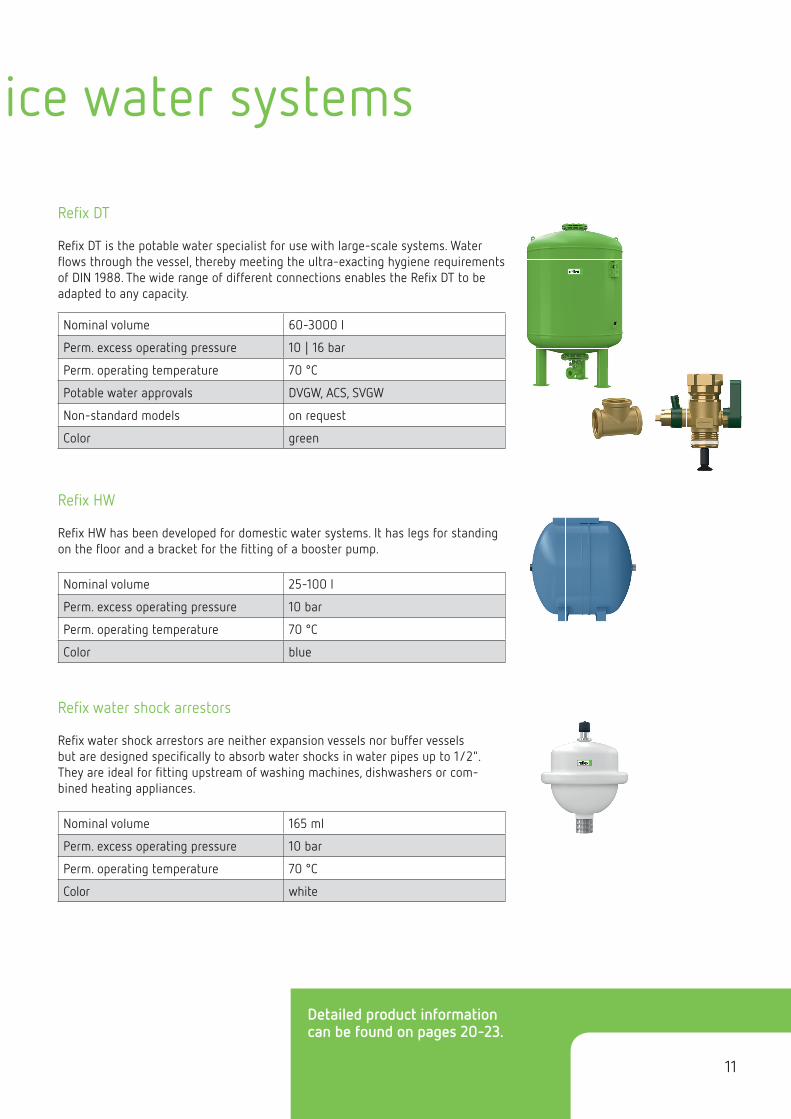
Refi x DT
Refi x DT is the potable water specialist for use with large-scale systems. Water fl ows through the vessel, thereby meeting the ultra-exacting hygiene requirements of DIN 1988. The wide range of different connections enables the Refi x DT to be adapted to any capacity.
Refi x HW
Refi x HW has been developed for domestic water systems. It has legs for standing on the fl oor and a bracket for the fi tting of a booster pump.
Refi x water shock arrestors
Refi x water shock arrestors are neither expansion vessels nor buffer vessels but are designed specifi cally to absorb water shocks in water pipes up to 1/2". They are ideal for fi tting upstream of washing machines, dishwashers or com-bined heating appliances.
Nominal volume 60-3000 l
Perm. excess operating pressure 10 | 16 bar
Perm. operating temperature 70 °C
Potable water approvals DVGW, ACS, SVGW
Non-standard models on request
Color green
Nominal volume 25-100 l
Perm. excess operating pressure 10 bar
Perm. operating temperature 70 °C
Color blue
Nominal volume 165 ml
Perm. excess operating pressure 10 bar
Perm. operating temperature 70 °C
Color white
BR_MAG_rz_EN_2.indd 12 07.03.13 12:16

Networked solutions with Refix
12
Refi x products can also be combined with the widest range of accessories. An extensive range of models guarantees a greater degree of safety, economy and durability, and thus also greater satisfaction amongst customers. This is how we create individual solutions to meet all possible requirements and projects.
Diaphragm expansion vessels
Refi x DD used as an expansion vessel in a hot water system
When heating potable water, for in-stance in a Refl ex Storatherm Aqua tank, pressure rises as the water ex-pands. In the worst case, the excess pressure is decreased by a safety valve, losing valuable heated potable water. The use of a Refi x DD diaphragm ex-pansion vessel remedies this situation by preventing the unnecessary use of the safety valve and providing for a more effi cient, resource-conserving operation of the system.
Refi x DT used as a buffer vessel in a booster system
Buffer vessels are still needed even in times of speed-controlled booster systems. Not only do they reduce the switching frequency of the pump but they can also signifi cantly reduce peak loads. Fitted on the input or follow-up pressure side, they directly affect the sizing of the supply lines and the booster system.
The extensive variety of connections ranges from the complete DN 32 Flowjet fl ow-through valve to the DN 100 T-connection, ensuring excellent adaptation of capacity.
Refi x DD used as an Refi x DT used as
Refi x DD saves water when combined with the Flowjet fl ow-through valve and is versatile enough to use with the most varied fl ow rates.
Refi x vessels are coated internally in compliance with the German KTW-A recommendations, conforming to technical requirements. A diaphragm rupture detector guarantees additional safety.
BR_MAG_rz_EN_2.indd 13 07.03.13 12:17

Networked solutions with Refix
13
Refi x DE used as an ex-pansion tank in a closed, oxygen-rich heating circuit
Oxygen is constantly diffusing in circuits with plastic pipes, drastically increasing the risk of corrosion. Underfl oor heating systems are affected by this, as are geothermal systems. Corrosion-proof Refi x DE diaphragm expansion vessels should be used to remedy this situation.
Refi x DE used as an ex-
A Longtherm plate heat exchanger combined with a Refi x DE is ideal for separating underfl oor heating systems. The Refl ex connection assembly rounds off the installation and operation perfectly.
BR_MAG_rz_EN_2.indd 14 07.03.13 12:18

Count on us – from the initial idea to the solution.
14
Diaphragm expansion vessels
Reflex offers a range of services to assist you in finding the solution that best suits your needs. Take advantage of our combined expertise and experience and develop professional and expert solutions together with us, down to the very last detail.
Made-to-measure design: With the Reflex Pro calculation program
Take the easiest route to correct design and sizing: Reflex Pro is the proven, continuously developed software solution you can use to quickly and simply achieve precise results. The software is available in three versions and we can also provide you with a CAD library of our entire product range for integration into your construction programs.
Visit www.reflex.de/pro for further information and the option of downloading free of charge.
Our service numbers
How can we help you? Please contact the relevant service number to ensure that you find the right person to deal with your inquiry as quickly as possible.
Technical hot line For all questions about our productsMonday to Friday from 8.00 to 16.30 +49 2382 7069-9546
Reflex Customer Service and Spare Parts Service To commission repairs, maintenance and commissioning and to order spare partsMonday to Friday from 8.00 to 16.30 +49 2382 7069-9505
Central numberFor general inquiries, to order brochures, contact a business partner or responsible field sales engineer Monday to Friday from 8.00 to 16.30 +49 2382 7069-0
BR_MAG_rz_EN_2.indd 15 07.03.13 12:18

Count on us – from the initial idea to the solution.
15
Our product literature – designed to be used
Make sure your decisions about all future steps are based on solid foundations – with Refl ex product information. You will fi nd everything you need to know about products and systems in our brochures and at www.refl ex.de. Well arranged and clearly explained – from the wider context to technical details.
Request the latest Refl ex brochures directly from your Refl ex fi eld sales engineer, via our central phone number or – even simpler – online as PDFs at www.refl ex.de.
Our fi eld sales team – always on the road for you
Our Refl ex fi eld sales team is your fi rst point of contact when you need professional advice on site. From recommending relevant products to design and support in the preparation of a tender. You can rely on our experts!
Call our central phone number or check out www.refl ex.de under Contact Us to fi nd the fi eld sales representative responsible for your region.
BR_MAG_rz_EN_2.indd 16 07.03.13 12:18

16
Vn Nominal volume/liters
Vn Nominal volume/liters
Technical dataRefl ex N
Refl ex F
• For heating and cooling water systems • With threaded connections• Non-replaceable diaphragm in accordance with
DIN 4807 T3, perm. operating temperature 70 °C• Approval in accordance with the Pressure Equipment
Directive 97/23/EC
• Flat vessel for heating and cooling water systems, especially suited for installation within the boiler
• Non-replaceable diaphragm in accordance with DIN 4807 T3, perm. operating temperature 70 °C
• From 18 liters supplied with suspension bracket• Approval in accordance with the Pressure Equipment
Directive 97/23/EC
Type6 bar/120 °C
Article no. gray white
Weight(kg)
Ø D(mm)
H(mm)
h(mm)
A Pre-set pressure (bar)
N 50 8209300 7209400 12.5 441 495 175 R ¾ 1.5
N 80 8210200 7210600 17.0 512 570 175 R 1 1.5
N 100 8216300 – 20.5 512 680 175 R 1 1.5
N 140 8211400 – 28.6 512 890 175 R 1 1.5
N 200 8213300 – 36.7 634 760 205 R 1 1.5
N 250 8214300 – 45.0 634 890 205 R 1 1.5
N 300 8215300 – 52.0 634 1060 235 R 1 1.5
N 400 8218000 – 65.0 740 1070 245 R 1 1.5
N 500 8218300 – 79.0 740 1290 245 R 1 1.5
N 600 8218400 – 85.0 740 1530 245 R 1 1.5
N 800 8218500 – 103.5 740 1995 245 R 1 1.5
N 1000 8218600 – 120.0 740 2410 245 R 1 1.5
Type3 bar/120 °C
Article no. gray white
Weight(kg)
Ø D(mm)
H(mm)
h(mm)
A Pre-set pressure (bar)
N 8 8202500 7202800 1.9 206 285 – R ¾ 1.5
N 12 8203300 7203500 2.6 272 315 – R ¾ 1.5
N 18 8204300 7204400 3.5 308 360 – R ¾ 1.5
N 25 8206300 7206400 4.6 308 480 – R ¾ 1.5
N 35 8208400 7208500 5.4 376 465 130 R ¾ 1.5
Type3 bar/120 °C
Article no.white
Weight(kg)
H(mm)
W(mm)
D(mm)
A Pre-set pressure (bar)
F 8 9600011 6.5 389 389 88 G 0.75
F 12 9600030 8.5 444 350 108 G ½ 1.0
F 15 9600040 9.0 444 350 134 G ¾ 1.0
F 18 9600000 9.5 444 350 158 G ¾ 1.0
F 24 9600010 9.8 444 350 180 G ¾ 1.0
Diaphragm expansion vessels
8 l 12–24 l
Ø D
A
Ø D
H H
h
B BT T
H HH H
A A
BR_MAG_rz_EN_2.indd 17 07.03.13 12:19

17
Refl ex G
• For heating and cooling water systems • With threaded connections up to 1,000 l Ø 740• With fl ange connections PN 6 at 6 bar and PN 16 at 10 bar• Replaceable bladder in accordance with DIN 4807 T3,
perm. operating temperature 70 °C• Approval in accordance with the Pressure Equipment
Directive 97/23/EC• With inspection port• With pressure gauge in the nitrogen chamber
Non-standard models on request
• Special vessel > 5,000 liters• Special vessel > 10 bar• Individual approval from a notifi ed body in accordance with the Pressure Equipment Directive 97/23/EC
Type6 bar/120 °C
Article no.gray
Weight(kg)
Ø D(mm)
H(mm)
h(mm)
A Pre-set pressure (bar)
G 400 8521605 51.0 740 1253 146 G 1 3.5
G 500 8521705 59.0 740 1473 146 G 1 3.5
G 600 8522605 74.0 740 1718 146 G 1 3.5
G 800 8523610 102.0 740 2183 146 G 1 3.5
G 1000 Ø 740 8546605 158.0 740 2593 146 G 1 3.5
G 1000 Ø 1000 8524605 248.0 1000 1975 305 DN 65/PN 6 3.5
G 1500 8526605 297.0 1200 1975 305 DN 65/PN 6 3.5
G 2000 8527605 370.0 1200 2430 305 DN 65/PN 6 3.5
G 3000 8544605 640.0 1500 2480 335 DN 65/PN 6 3.5
G 4000 8529605 828.0 1500 3055 335 DN 65/PN 6 3.5
G 5000 8530605 905.0 1500 3590 335 DN 65/PN 6 3.5
Type10 bar/120 °C
Article no.gray
Weight(kg)
Ø D(mm)
H(mm)
h(mm)
A Pre-set pressure (bar)
G 100 8518000 16.5 480 856 152 G 1 3.5
G 200 8518100 36.5 634 972 144 G 1 ¼ 3.5
G 300 8518200 41.6 634 1267 144 G 1 ¼ 3.5
G 400 8521005 59.0 740 1245 133 G 1 ¼ 3.5
G 500 8521006 65.1 740 1475 133 G 1 ¼ 3.5
G 600 8522006 128.0 740 1859 263 G 1 ½ 3.5
G 800 8523005 176.0 740 2324 263 G 1 ½ 3.5
G 1000 Ø 740 8546005 214.0 740 2604 263 G 1 ½ 3.5
G 1000 Ø 1000 8524005 355.0 1000 2000 290 DN 65/PN 16 3.5
G 1500 8526005 410.0 1200 2000 290 DN 65/PN 16 3.5
G 2000 8527005 505.0 1200 2450 290 DN 65/PN 16 3.5
G 3000 8544005 870.0 1500 2580 320 DN 65/PN 16 3.5
G 4000 8529005 1120.0 1500 3070 320 DN 65/PN 16 3.5
G 5000 8530005 1330.0 1500 3610 320 DN 65/PN 16 3.5
Vn Nominal volume/liters
Technical data
Ø D
H
h
BR_MAG_rz_EN_2.indd 18 07.03.13 12:19
Technical data
18
Diaphragm expansion vessels
Refl ex S
• For solar, heating, and cooling water applications • For up to 50% addition of anti-freeze • With threaded connections• Non-replaceable diaphragm in accordance with
DIN 4807 T3, perm. operating temperature 70 °C• Approval in accordance with the Pressure Equipment
Directive 97/23/EC
Type10 bar/120 °C
Article no. gray white
Weight(kg)
Ø D(mm)
H(mm)
h(mm)
A Pre-set pressure (bar)
S 2 8707700 – 1.1 132 260 – G ¾ 0.5
S 8 8703900 9702600 2.5 206 325 – G ¾ 1.5
S 12 8704000 9702700 3.5 280 300 – G ¾ 1.5
S 18 8704100 9702800 4.5 280 380 – G ¾ 1.5
S 25 8704200 9702900 5.5 280 500 – G ¾ 1.5
S 33 8706200 9706300 6.3 354 450 – G ¾ 1.5
S 50 8209500 – 13.2 409 469 168 R ¾ 3.0
S 80 8210300 – 18.4 480 538 166 R 1 3.0
S 100 8210500 – 22.7 480 644 166 R 1 3.0
S 140 8211500 – 29.0 480 886 166 R 1 3.0
S 200 8213400 – 40.0 634 760 205 R 1 3.0
S 250 8214400 – 48.0 634 890 205 R 1 3.0
S 300 8215400 – 54.0 634 1060 235 R 1 3.0
S 400 8219000 – 78.0 740 1070 245 R 1 3.0
S 500 8219100 – 80.0 740 1290 245 R 1 3.0
S 600 8219200 – 103.0 740 1530 245 R 1 3.0
Vn Nominal volume/liters
Vn Nominal volume/liters
Refl ex C
• For heating and cooling water systems • For up to 50% addition of anti-freeze • Incl. wall bracket for ease of installation • Butyl bladder in accordance with DIN 4807 T3,
perm. operating temperature 70 °C• Approval in accordance with the Pressure Equipment
Directive 97/23/EC
Type3 bar/120 °C
Article no.gray
Weight(kg)
Ø D(mm)
H(mm)
L(mm)
W(mm)
A Pre-set pressure (bar)
C 8 8280000 2.5 280 287 163 52 R ½ 1.0
C 12 8280100 4.0 354 361 168 64 R ½ 1.0
C 18 8280200 4.6 354 367 222 76 R ¾ 1.0
C 25 8280300 5.8 409 419 239 93 R ¾ 1.0
C 35 8280400 7.3 480 457 240 97 R ¾ 1.0
C 50 8280500 8.6 480 457 317 125 R ¾ 1.5
C 80 8280600 15.6 634 612 325 135 R ¾ 1.5
Ø D
A
H
Ø D
H
h
BR_MAG_rz_EN_2.indd 19 07.03.13 12:20

95Rp ½
Filling connection Manometer connection Rp ⅜
Vent connection Rp ⅜
30Expansion pipe
connection Rp ¾Expansion vessel connection Rp ¾
DN 32
95
30
280
210
h
Ø D
A
H
19
• Required for systems with return temperatures > 70 °C or in cooling systems at ≤ 0 °C• Approval in accordance with the Pressure Equipment Directive 97/23/EC• Use as a buffer vessel• Refl ex in-line vessels > 5,000 liters, > 120 °C and pressures ≥ 10 bar on request
Type10 bar/120 °C
Article no. gray
Weight(kg)
Ø D(mm)
H(mm)
h(mm)
A
V 6 8403100 2.0 206 245 – R ¾
V 12 8403200 3.0 280 285 – R ¾
V 20 8402000 4.0 280 360 – R ¾
V 40 8403400 9.4 409 562 113 R 1
V 60 8402600 23.0 409 760 174 R 1
V 200 8701800 43.0 634 900 142 DN 40/PN 16
V 300 8701900 48.0 634 1200 142 DN 40/PN 16
V 350 8702400 51.0 640 1385 210 DN 40/PN 16
V 1000 8400205 675.0 1000 2055 285 DN 65/PN 16
V 1500 8400305 935.0 1200 2055 285 DN 65/PN 16
V 2000 8400405 960.0 1200 2055 285 DN 65/PN 16
V 3000 8400505 1685.0 1500 2600 315 DN 65/PN 16
V 4000 8400605 2315.0 1500 3180 315 DN 65/PN 16
V 5000 8400705 2420.0 1500 3720 315 DN 65/PN 16
Type6 bar/120 °C
Article no. gray
Weight(kg)
Ø D(mm)
H(mm)
h(mm)
A
V 500 8852800 79.0 750 1660 210 DN 40/PN 6
V 750 8851800 325.0 750 2310 210 DN 40/PN 6
V 1000 8851905 560.0 1000 2020 305 DN 65/PN 6
V 1500 8852305 780.0 1200 2020 305 DN 65/PN 6
V 2000 8852405 940.0 1200 2480 305 DN 65/PN 6
V 3000 8852505 1405.0 1500 2560 340 DN 65/PN 6
V 4000 8853405 1930.0 1500 3130 340 DN 65/PN 6
V 5000 8854805 2015.0 1500 3637 340 DN 65/PN 6
AccessoriesRefl ex in-line vessels
• Bracket with multiple connections, for Refl ex 8 – 25 liters with a top vessel connection Article no.: 7612000
• Bracket with tightening strap for Refl ex 8 – 25 liters, vertical assembly, top or bottom vessel connection Article no.: 7611000
Secured shut-offs
• Refl ex lockshield valve R ¾ Article no.: 7613000• Refl ex lockshield valve R 1 Article no.: 7613100• Refl ex connection group 1 Article no.: 9119204• Refl ex connection group 1 ¼ Article no.: 9119205• Refl ex connection group 1 ½ Article no.: 9119206
Digital test manometer
• Refl ex pre-set pressure gauge up to around 9 bar Article no.: 9119198
• Signals in the event of diaphragm rupture in Refl ex G. For more information, see page 23.
Vn Nominal volume/liters Vn Nominal volume/liters
Refl ex wall bracket
Diaphragm rupture detector
1) Available from August 1, 2013, until then the items in the gross price list 2012 apply
1) Available from August 1, 2013, until then the items in the gross price list 2012 apply
BR_MAG_rz_EN_2.indd 20 07.03.13 12:20

20
Technical dataDiaphragm expansion vessels
Refi x DD
• For potable water systems, pressure booster systems, and hot water systems in accordance with DIN 1988, stainless steel connection
• Integrated internal circulation by High-Flow fl ow system• Butyl bladder in accordance with DIN 4807 T3+5,
KTW-C and W 270• Built and tested in accordance with DIN 4807 T5,
DIN DVGW reg. no. NW-0411AT2534• Approval in accordance with the Pressure Equipment
Directive 97/23/EC• Coated outside and inside in compliance with KTW-A• Can be combined with Flowjet fl ow-through valve
Vn Nominal volume/liters
Refl ex wall bracket
• Bracket with tightening strap for 8 - 25 liter vessels• Ultra-simple assembly
Article no.: 7611000
¾ Flowjet flow-through, shut-off and discharge valve
• Perm. excess operating pressure 16 bar• Perm. operating temperature 70 °C• Connections on both sides G ¾“, m/f thread• Can be combined with T-pieces (by others) with nominal width 1"
Article no.: 9116799
Accessories
Type10 bar/70 °C
Article no. green white
Weight(kg)
D(mm)
H(mm)
h(mm)
A
DD 2 7381500 – 1.0 132 260 – G ¾
DD 8 7308000 7307700 1.9 206 335 – G ¾
DD 12 7308200 7307800 2.3 280 325 – G ¾
DD 18 7308300 7307900 2.8 280 395 – G ¾
DD 25 7308400 7380400 3.7 280 515 – G ¾
DD 33 7380700 7380800 6.6 354 465 – G ¾
Type25 bar/70 °C
Article no. green white
Weight(kg)
D(mm)
H(mm)
h(mm)
A
DD 8 7290200 7290300 3.4 206 335 – G ¾
Ø D
A
H
BR_MAG_rz_EN_2.indd 21 07.03.13 12:20

21
Technical dataRefi x DT
• For potable water systems, pressure booster systems, and hot water systems in accordance with DIN 1988
• With Flowjet fl ow-through, shut-off and discharge valve or duo-connection
• Replaceable butyl bladder in accordance with DIN 4807 T3+5, KTW-C and W 270
• Built and tested in accordance with DIN 4807 T5, DIN DVGW reg. no. NW-0411AT2094
• Approval in accordance with the Pressure Equipment Directive 97/23/EC
• Coated outside and inside in compliance with KTW-A
Pre-set ConnectionType Article no. Weight Ø D H h* pressure Flowjet DN 50 DN 65 DN 80 DN 100
10 bar/70 °C green (kg) (mm) (mm) (mm) (bar) Rp 1 ¾ PN 16 DT 60 7309000 15.0 409 766 80 4.0 ●
DT 80 7309100 17.0 480 750 65 4.0 ● O O O
DT 100 7309200 20.0 480 835 65 4.0 ● O O O
DT 200 7309300 47.0 635 975 80 4.0 ● O O O
DT 300 7309400 53.0 635 1275 80 4.0 ● O O O
DT 400 7319305 70.0 740 1245 70 4.0 ● O O O
DT 500 7309500 79.0 740 1475 70 4.0 ● O O O
DT 600 7365600 155.0 740 1860 235 4.0 ● O O
DT 800 7365700 195.0 740 2325 235 4.0 ● O O
DT 1000 Ø 740 7365800 228.0 740 2604 235 4.0 ● O O
DT 1000 Ø 1000 7320105 424.0 1000 2000 160 4.0 ● O O
DT 1500 7320305 539.0 1200 2000 160 4.0 ● O O
DT 2000 7320505 714.0 1200 2450 160 4.0 ● O O
DT 3000 7320705 1054.0 1500 2520 190 4.0 ● O O
Pre-set ConnectionType Article no. Weight Ø D H h* pressure Flowjet DN 50 DN 65 DN 80 DN 100
16 bar/70 °C green (kg) (mm) (mm) (mm) (bar) Rp 1 3/4 PN 16 DT 80 7316005 27.0 480 750 65 4.0 ● O O O
DT 100 7365408 29.0 480 835 65 4.0 ● O O O
DT 200 7365108 55.0 635 975 80 4.0 ● O O O
DT 300 7319205 57.0 635 1275 80 4.0 ● O O O
DT 400 7370400 109.0 740 1395 235 4.0 ● O O
DT 500 7370500 121.0 740 1615 235 4.0 ● O O
DT 600 7370600 165.0 740 1860 235 4.0 ● O O
DT 800 7370700 215.0 740 2325 235 4.0 ● O O
DT 1000 Ø 740 7370800 241.0 740 2604 235 4.0 ● O O
DT 1000 Ø 1000 7320205 530.0 1000 2000 160 4.0 ● O O
DT 1500 7320405 685.0 1200 2000 160 4.0 ● O O
DT 2000 7320605 895.0 1200 2450 160 4.0 ● O O
DT 3000 7320805 1240.0 1500 2520 190 4.0 ● O O
Vn Nominal volume/liters * Dimension h applies to the standard model
● Standard model
O Connection versions (Refer to price list for article nos.)
Ø D Ø D
H H
h h
BR_MAG_rz_EN_2.indd 22 07.03.13 12:21

• For systems not subject to DIN 1988 requirements, e.g. fi re-extinguishing and service water systems, underfl oor heating
• Without fl ow-through, shut-off and discharge valve• Replaceable bladder in accordance with DIN 4807 T3/ from 50 liters can be replaced• Parts that come into contact with water are corrosion-proof• Approval in accordance with the Pressure Equipment
Directive 97/23/EC• Pre-set pressure: 4.0 bar
22
Technical dataDiaphragm expansion vessels
Refi x DE
Ø D
A
H
Typ 10 bar/70 °C
Artikel-Nr.blau
Gewicht(kg)
Ø D(mm)
H(mm)
h(mm)
A
DE 2 7200300 1,0 132 260 – G ¾
DE 8 7301000 1,7 206 316 – G ¾
DE 12 7302000 2,4 280 307 – G ¾
DE 18 7303000 2,8 280 377 – G ¾
DE 25 7304000 3,7 280 496 – G ¾
DE 33 7303900 5,7 354 454 – G ¾
DE 331) 7305500 6,5 354 520 66 G ¾
DE 50 7306005 9,5 409 604 102 G 1
DE 60 7306400 11,2 409 734 161 G 1
DE 80 7306500 14,0 480 729 153 G 1
DE 100 7306600 16,0 480 834 153 G 1
DE 200 7306700 36,5 634 967 150 G 1 ¼
DE 300 7306800 41,5 634 1267 150 G 1 ¼
DE 400 7306850 73,0 740 1245 139 G 1 ¼
DE 500 7306900 103,0 740 1475 133 G 1 ¼
DE 600 7306950 128,0 740 1859 263 G 1 ½
DE 800 7306960 176,0 740 2325 263 G 1 ½
DE 10002) 7306970 214,0 740 2604 263 G 1 ½
DE 10003) 7311405 427,0 1000 2001 286 DN 65/PN 16
DE 1500 7311605 542,0 1200 1991 291 DN 65/PN 16
DE 2000 7311705 717,0 1200 2451 291 DN 65/PN 16
DE 3000 7311805 962,0 1500 2521 320 DN 65/PN 16
DE 4000 7354000 1058,0 1500 3070 320 DN 65/PN 16
DE 5000 7354200 1050,0 1500 3635 320 DN 65/PN 16
Type 10 bar/70 °C
Article no.blue
Weight(kg)
Ø D(mm)
H(mm)
h(mm)
A
DE 2 7200300 1.0 132 260 – G ¾
DE 8 7301000 1.7 206 316 – G ¾
DE 12 7302000 2.4 280 307 – G ¾
DE 18 7303000 2.8 280 377 – G ¾
DE 25 7304000 3.7 280 496 – G ¾
DE 33 7303900 5.7 354 454 – G ¾
DE 331) 7305500 6.5 354 520 66 G ¾
DE 50 7306005 9.5 409 604 102 G 1
DE 60 7306400 11.2 409 734 161 G 1
DE 80 7306500 14.0 480 729 153 G 1
DE 100 7306600 16.0 480 834 153 G 1
DE 200 7306700 36.5 634 967 150 G 1 ¼
DE 300 7306800 41.5 634 1267 150 G 1 ¼
DE 400 7306850 73.0 740 1245 139 G 1 ¼
DE 500 7306900 103.0 740 1475 133 G 1 ¼
DE 600 7306950 128.0 740 1859 263 G 1 ½
DE 800 7306960 176.0 740 2325 263 G 1 ½
DE 10002) 7306970 214.0 740 2604 263 G 1 ½
DE 10003) 7311405 427.0 1000 2001 286 DN 65/PN 16
DE 1500 7311605 542.0 1200 1991 291 DN 65/PN 16
DE 2000 7311705 717.0 1200 2451 291 DN 65/PN 16
DE 3000 7311805 962.0 1500 2521 320 DN 65/PN 16
DE 4000 7354000 1085.0 1500 3070 320 DN 65/PN 16
DE 5000 7354200 1050.0 1500 3635 320 DN 65/PN 16
Type 16 bar/70 °C
Article no.blue
Weight(kg)
Ø D(mm)
H(mm)
h(mm)
A
DE 8 7301006 2.7 206 321 – G ¾
DE 12 7302105 3.5 280 309 – G ¾
DE 25 7304015 5.6 280 499 – G ¾
DE 80 7348600 33.0 480 729 153 G 1
DE 100 7348610 27.0 480 834 153 G 1
DE 200 7348620 57.0 634 967 150 G 1 ¼
DE 300 7348630 66.0 634 1267 150 G 1 ¼
DE 400 7348640 116.0 740 1394 265 G 1 ½
DE 500 7348650 127.0 740 1614 265 G 1 ½
DE 600 7348660 158.0 740 1859 265 G 1 ½
DE 800 7348670 202.0 740 2324 265 G 1 ½
DE 10002) 7348680 244.0 740 2604 265 G 1 ½
DE 10003) 7312805 530.0 1000 2001 286 DN 65/PN 16
DE 1500 7312905 685.0 1200 1991 291 DN 65/PN 16
DE 2000 7313005 895.0 1200 2451 291 DN 65/PN 16
DE 3000 7313105 1240.0 1500 2521 320 DN 65/PN 16
DE 4000 7354100 1100.0 1500 3110 320 DN 65/PN 16
DE 5000 7354300 1120.0 1500 3645 320 DN 65/PN 16
Vn Nominal volume/liters1) with legs 2) Ø 740 mm 3) Ø 1000 mm
Type 25 bar/70 °C
Article no.blue
Weight(kg)
Ø D(mm)
H(mm)
h(mm)
A
DE 8 7290100 3.5 206 321 – G ¾
DE 80 7317600 70.0 450 942 159 DN 50/PN 4
DE 120 7313700 100.0 450 1253 159 DN 50/PN 4
DE 180 7313500 116.0 450 1528 159 DN 50/PN 4
DE 300 7313800 150.0 750 1318 160 DN 50/PN 4
DE 400 7313300 245.0 750 1423 160 DN 50/PN 4
DE 600 7321500 290.0 750 1868 159 DN 50/PN 4
DE 800 7321200 335.0 750 2268 159 DN 50/PN 4
DE 10002) 7321000 245.0 750 2768 159 DN 50/PN 4
DE 10003) 7322200 800.0 1000 2051 242 DN 65/PN 4
DE 1500 7322100 680.0 1200 2071 291 DN 65/PN 4
DE 2000 7313400 895.0 1200 2531 240 DN 65/PN 4
DE 3000 7345700 1550.0 1500 2609 269 DN 65/PN 4
Vn Nominal volume/liters
BR_MAG_rz_EN_2.indd 23 07.03.13 12:21

• For use as buffer vessel for domestic water systems that are not subject to DIN 1988 requirements
• Vessel surface and parts that come into contact with the water are plastic-coated
• For systems not subject to DIN 1988 requirements, e.g. fi re-extinguishing and service water systems, underfl oor heating
• Without fl ow-through, shut-off and discharge valve• Non-replaceable diaphragm in accordance with DIN 4807 T3• Parts that come into contact with water are corrosion-proof• Approval in accordance with the Pressure Equipment Directive 97/23/EC
23
Refi x DC
Refi x HW
Type10 bar/70 °C
Article no.blue
Weight(kg)
Ø D(mm)
H(mm)
h(mm)
A Pre-set pressure bar)
DC 50 7309600 13.2 409 605 115 R 1 4.0
DC 80 7309700 18.4 480 665 105 R 1 4.0
DC 100 7309800 22.7 480 770 105 R 1 4.0
DC 140 7309900 29.0 480 1015 105 R 1 4.0
DC 200 7363500 40.0 634 885 90 R 1 4.0
DC 300 7363600 54.0 634 1185 90 R 1 4.0
DC 400 7363700 78.0 740 1175 80 R 1 4.0
DC 500 7363800 80.0 740 1390 80 R 1 4.0
DC 600 7363900 103.0 740 1630 75 R 1 4.0
Type10 bar/70 °C
Article no.blue
Weight(kg)
Ø D(mm)
H(mm)
L(mm)
F(mm)
W(mm)
C(mm)
A Pre-set pressure (bar)
HW 25 7200200 5.6 280 294 484 228 214 270 G 1 1.5
HW 50 7308805 15.0 409 434 492 175 285 350 G 1 1.5
HW 80 7200260 18.0 480 504 562 193 285 350 G 1 1.5
HW 100 7200250 21.0 480 504 667 303 285 350 G 1 1.5
Vn Nominal volume/liters
Vn Nominal volume/liters
• Signals in the event of diaphragm rupture in the Refi x DT and Refl ex G above 60 liters • Consisting of an electrode relay and an electrode (factory-fi tted)• Voltage supply 230 V/50 Hz• Floating output (changeover switch)• Only supplied in conjunction with a vessel
Article no.: 7857700
Diaphragm rupture detector
Accessories
Ø D
H
hA
H A
L
BR_MAG_rz_EN_2.indd 24 07.03.13 12:21

PI13
27en
/ 9
5713
45 /
02
- 13
/ 1
0.00
0Su
bjec
t to
tech
nica
l mod
ifi ca
tions
Reflex Winkelmann GmbHGersteinstrasse 19
59227 Ahlen, Germany
Tel.: +49 2382 7069-0Fax: +49 2382 7069-588
www.reflex.de
BR_MAG_rz_EN_2.indd 1 07.03.13 12:07