diagnostics_2.pdf
DESCRIPTION
yioiTRANSCRIPT

Optical methods for near nozzle spray characterisation
Y. Hardalupas & A.M.K.P. TaylorImperial College London
Mechanical Engineering DepartmentLondon SW7 2BX, UK
Autumn meeting of the Combustion Institute, British Section “Atomisation and Spray Combustion”
Imperial College London, 26 September 2007

Spray formationCoaxial air-liquid jets Liquid jet in Cross Flow of air
(S.M. Thawley 2006, MSc thesis, Virginia State University)
1. Liquid Jet Intact Length- Where Does it end?
2. Ligament break-up- What is the size and
velocity?3. Dense Spray region
- What is the size and velocity?- Does it matter?
4. Droplet Cluster Formation- Why are they formed?
- How large are the spray spatial & temporal
fluctuations?
5. Planar Droplet Sizing Velocimetry- Tracking of
individual droplets
Experimental techniques
1. Liquid jet intact length2. Sizing of ligaments (non-spherical)3. Measurement of droplet clustering in
dense sprays4. Measurement of individual droplet sizes
and velocities

Fluorescence imaging for Liquid jet intact length
• Charalampous et al (2007), AIAA paper no. 2007-1337• Charalampous et al (2007), Int. Conf. on Multiphase Flows (ICMF),
Leipsig, Germany.

Lighting of Water Fountains
• Illumination from below and the side of the liquid jet source
• Observation of scattered light from liquid jet and droplets
• However, liquid jet breaks up earlier than the image suggests
• Liquid droplets cause multiple scattering and generate noise on the image

Fluorescence Imaging approach• Introduction of the laser beam through
liquid injection nozzle• Propagation of laser beam along intact
liquid jet core, which acts as an optical fiber
• Break-up of liquid jet interrupts light propagation, so light intensity change identifies the intact core length
• Addition of fluorescing dye in the atomizing liquid, so that all the liquid volume is observed
• Addition of optical filter to collect fluorescent intensity eliminates scattered light from droplets
Intact Core Length
Laser Beam introduced into
nozzle
Liquid flow
Dye in intact liquid core is fluorescing
Dye in detached droplets not fluorescing because initial laser light does not propagate after liquid jet breaks

Experimental Set-up• Airblast Atomizer (modified with optical
access to the nozzle)
• Nd:YAG pulsed laser at 532 nm for LIF
• Rhodamine WT fluorescent dye
• Nanosecond-Flashlamp for shadowgraph comparison
• Two 16-bit ICCD cameras (one for LIF, one for shadowgraph)
• Optical filters
Shadowgraph Camera
LIF Camera
Dichroic filter
Fluorescing Continuous Spray Core

Experimental Set-up (Coaxial AirblastAtomizer) Laser beam access
Atomizer
Laser Beam Alignment
Optics
Flashlamp

Shadowgraphy vs. Laser Induced Fluorescence (LIF) Imaging 34mm
Fig 1a Fig 1b
Fig 2a Fig 2b
We ~ 10
MR ~ 4
We ~ 25
MR ~ 23
• Shadowgraphic images are influenced by droplets around the liquid jet core. Difficult to identify location of intact length core.
• LIF image is clear. No interference by surrounding droplets/ligaments.
• LIF measures shorter intact liquid jet core
Flow 1c
Flow 1d
Shadowgraphy LIF

Liquid jet intact core as a function of Momentum Ratio (MR)
02468
10121416
0 100 200 300 400MR
L/DL
Flows 1a-1d (LIF)
Flows 1a-1d (Shadowgraphy)
Flows 2a-2d (LIF)
Flows 2a-2d (Shadowgraphy)
Engelbert et al
• Measured values from each technique follow a general single trend for all flow conditions
• Consistently intact core length measured by LIF is shorter than that from shadowgraphy.
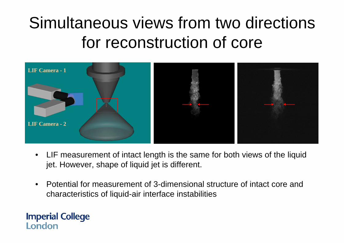
Simultaneous views from two directions for reconstruction of core
• LIF measurement of intact length is the same for both views of the liquid jet. However, shape of liquid jet is different.
• Potential for measurement of 3-dimensional structure of intact core and characteristics of liquid-air interface instabilities
LIF Camera - 1
LIF Camera - 2

Detection of liquid Core instabilities
Identification of surface contour to detect core tip location, wavelengths of surface instabilities, …

Demonstration in modified Diesel injector
View along the injector axis of the scattered light image, when illuminated by flashlamp
• Metering injector: operated at 80 MPa, 0.6 ms injection duration, corresponding to 1.8 CAD at 500 rpm.
• Atomising injector: injection duration 1.92 ms, corrresponding to 5.76 CAD at 500 rpm
Image measured with the laser beam illumination through the nozzle
Metering injector
Atomising injector

Shadow Doppler Velocimeter for measurement of ligaments and non-
spherical droplets
• Hardalupas et al, "Shadow Doppler Technique for sizing particles of arbitrary shape", Applied Optics 33, (1994), 8417 – 8426.
• Hardalupas et al, “Prototype Probe Design and Operating Experience for In Situ Measurements of Particle Size and Velocity in Co-Current Flow Spray Dryer and Spray Dryer Atomisers Using Shadow Doppler Velocimetry”, Spray Drying ’01, Dortmund (2001).

The Shadow Doppler Velocimeter(SDV) - 1
Magnified Projection of droplet passing through the crossing point of two laser beams
V
Linear Diode Array
Distance along the array

The Shadow Doppler Velocimeter(SDV) - 2
Microscope Objective Relay LensMicroscope Objective Relay LensMicroscope Objective Relay Lens
Linear Diode ArrayLinear Diode Array
Measurements of Size, Shape, 2D Velocity and Concentration of individual non-spherical droplets

SDV: Droplet measurement close to liquid film surface
From Matsuura et al, ILASS Europe 2002, Zaragoza 9 –11 September 2002
High Magnification Imaging of breaking droplets from film
SDV of detached droplet
Liquid film
Droplet

Planar Droplet Sizing for droplet clustering measurement in dense
sprays• Domann, R. & Hardalupas, Y., “Spatial distribution of fluorescence intensity within large droplets and its
dependence on dye concentration”. Applied Optics 40, (2001), 3586-3597.• Domann R. & Hardalupas Y. “Quantitative Measurements of planar Droplet Sauter Mean Diameter in
Sprays using Planar Droplet Sizing” Part. Part. Syst. Charact. 20, (2003) 209 - 218. • Zimmer L., Domann R., Hardalupas Y. and Ikeda Y. “Simultaneous Laser Induced Fluorescence and Mie
scattering for droplet cluster measurements”. AIAA J. 41, (2003) 2170-2178.• Domann, R. & Hardalupas, Y., “Characterisation of spray unsteadiness” in Proceedings 18th Annual
Conference on Liquid Atomisation & Spray Systems (ILASS-Europe 2002), Lozano A. ed., 2002, 287-292.• Domann, R. and Hardalupas, Y., “Planar droplet sizing for characterisation of spray unsteadiness”. In
“Proceedings 10th Workshop on Two-Phase Flow predictions”, Sommerfeld M ed., 2002, 364-373.• Charalampous et al. “Optimisation of the Droplet Sizing Accuracy of the combined Scattering (Mie) / Laser
Induced Fluorescence (LIF) technique” in “Proceedings 12th Int. Symp. on Application of Laser Techniques to Fluid Mechanics, Adrian R.J. et al. eds., Lisbon, Portugal, 12-15 July 2004, paper 15.6.

Planar Droplet Sizing in dense sprays
aaK
s
f=
In a cloud of Droplets
Calibration Constant
( )( )∑
∑∑∑
=
=
=
= == m
j jscatteredj
m
j jcefluorescen
m
j j
m
j j
DiDi
KDDSMD
1 ,
1
1
2
1
3 1
Scattered Light
Fluorescence Light
Imaged Area
Liquid Volume
Liquid Surface Area

Calibration parameter is not Constant
0.0E+00
5.0E-17
1.0E-16
1.5E-16
2.0E-16
2.5E-16
3.0E-16
0 50 100 150 200SMD (µm)
K
The calibration parameter K varies with
• Droplet size
• Scattering angle
• Dye concentration
Internal droplet fluorescence intensity
distribution.Dye concentration
0.001 g/l
Experiment Calculation

Advanced signal processing for increased accuracy
1. Determination of constant Kfit=af/as from the scattering and fluorescence intensity calculations
2. Initial Estimate of SMD by Kfit
3. New value of K, Kcorr, from the Main Trend of Kreal
4. Recalculation of SMD 5. Repeat steps 3 and 4 until
SMD value converges

Burner geometry and Air Flow
AtomiserBluff body
Dis
tanc
e al
ong
the
Cent
relin
e (m
m) Air Flow
Recirculation Zone downstream of bluff body

Instantaneous Spray Characteristics
Surface area Liquid volume SMD (quantitative)
• Droplet Clusters are visible and will be quantified
e.g. how are regions of high surface area (clusters) related to instantaneous liquid volume and SMD variations ?

Deviation of instantaneous droplet surface area from the mean
Mean of 800 measurements Instantaneous measurement Instantaneous fluctuations
• Provide statistical information about length scales of clusters
deviations from the mean surface area distribution
• Provide statistical information about magnitude of the fluctuations
Droplet Clusters

Probability of droplet cluster location and high vorticity in air flow
Coloured contours:
PDF of droplet clusters
Line contours:
PDF of high vorticity eddies in
air flow

Suggested Physical Mechanism of Droplet Cluster Generation
Droplets with SMD = 30 microns can be centrifuged by the air flow eddies
Eddy lengthscale
Droplets with SMD = 10 microns follow the air flow eddies
Lengthscale of droplet cluster
Counter-rotating vortices (eddies) in the air flow turbulence are responsible for the formation of droplet clusters
A mechanism responsible for formation of droplet clusters with negative correlation between SMD and surface area was associated with droplet response to air flow turbulence

Cyclic Variations of Fuel-Droplet
Distribution during the Early Intake
Stroke in a VTEC gasoline engine
In-cylinder droplet distribution
Aleiferis, P. G., Hardalupas, Y., Taylor, A. M. K. P., Ishii, K. & Urata, Y. Experiments in Fluids 39 (2005) 780-798.

Possible origin of cycle-to-cycle variability of in-cylinder fuel distribution
Spray Impingement on main inlet valve
In cylinder droplet location for ‘good’ cycle
(leads to ‘good’ fuel stratification)
In cylinder droplet location for ‘bad’ cycle
(leads to ‘bad’ fuel stratification)

Image Processing of droplet scattering• Eliminate Engine Vibration Effects
Shift Image in Space by PIV-type Cross Correlation with Image of the Engine Head atRest
• Background Subtraction
Raw Image of Fuel Droplets Processed Image of Fuel Droplets

Fuel-Droplet Distribution for Cycles of High & Low IMEP
Conditionally Averaged Difference from the Mean Droplet Distribution:
(1) Good Cycles (2) Bad Cycles Difference: (1)-(2)IMEP > 1.15⋅IMEPMEAN IMEP < 0.85⋅IMEPMEAN
30% of the Pattern Area of (1) Scatters 20% More Light Intensity, ∆I
∆I due to More Droplets of Same Size: ∆I∝n, ∆m∝n ⇒ 20% More Fuel in 30% Area
∆I due to Same Number of Larger Droplets: ∆I∝D2, ∆m∝D3, ∆m∝∆I3/2 ⇒ 203/2% More Fuel in 30% Area
Finally: 6–26% Difference in Fuel, i.e. ∆Φ≈0.17 ⇒ Good Agreement with Φ of Reacting Mixture

Planar Droplet Sizing Velocimetry for Tracking of individual droplets:
Interferometric Laser Imaging Droplet Sizing (ILIDS)
• Glover et al, (1995) Interferometric laser imaging for droplet sizing : a method for droplet size measurement in sparce spray systems. Appl. Optics 34, 8409-8421.
• Kawagushi et al (2002) Size measurements of droplets and bubbles by advanced interferometric laser imaging technique Meas. Sci. Technol. 13, 308–316.
• Hardalupas et al, (2004) “Sizing Spheroidal Droplets by ILIDS” in Proc. 7th Int. Congress on Optical Particle Characterisation, 1-5 August 2004, Kyoto, Japan, paper 66
• Sugimoto et al. (2006). “Extension of the compressed interferometric particle sizing technique for three component velocity measurements”. In Proc 13th Int. Symp. on Applic. of Laser Techniques to Fluid Mechanics, Lisbon, Portugal, July 2006.
• Matsuura et al. (2006). “Simultaneous planar measurement of size and three-component velocity of droplets in an aero-engine airblast fuel spray by stereoscopic interferometriclaser imaging technique”. In Proc. 10th Int. Conf. on Liquid Atomisation and Spraying Systems (ICLASS-2006), Kyoto, Japan, August 2006.

Principle of Interferometric Laser Imaging Droplet Sizing (ILIDS)
In-foc
usIm
aging
plan
e
Slightl
y Out-
of-
focus
imag
ing
plane
Out-of-
focus
imag
ing pl
ane
Receiv
ing
Lens
Imag
ing IC
CD
Circula
r Ape
rture
Illuminated Droplet
Resulting Image
Laser
Resulting Image
Resulting Image
(ILIDS)
Fringe spacing provides size information
Note: Fringe spacing represents the frequency of scattered light intensity fluctuations

ILIDS Spray Images
• Overlapping fringe patterns can be an issue when many droplets exist
Spray Region Focused Image Defocused Image with Fringe Patterns

Compression Optics Assembly
Fringe Pattern
Fringe PatternCircular Aperture
ImagingLensDroplet
ImagingLens
Rectangular Aperture
Cylindrical Lenses
Droplet
Without Compression With Compression
Planar measurement of individual droplet size and 2D velocity in spray regions where a Phase Doppler
Anemometer can measure

Stereoscopic ILIDS
• Stereoscopic ILIDS for simultaneous measurement of 3 velocity components and droplet size
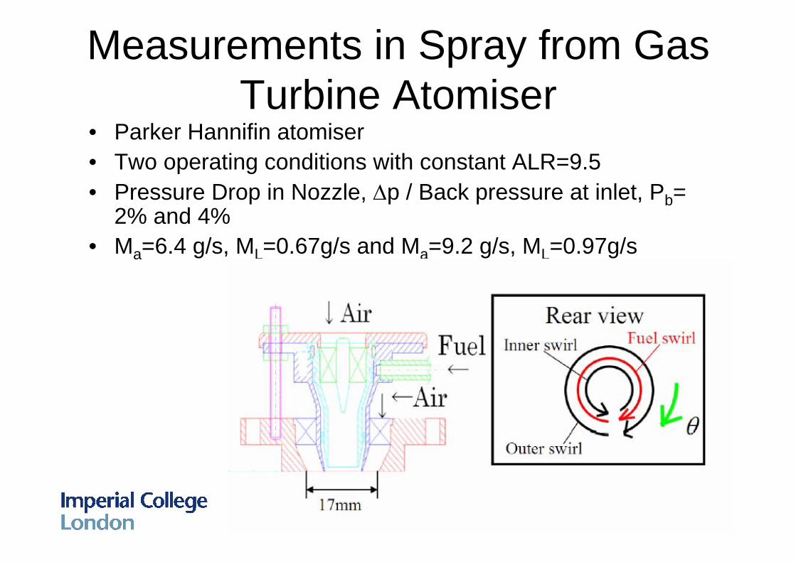
Measurements in Spray from Gas Turbine Atomiser
• Parker Hannifin atomiser• Two operating conditions with constant ALR=9.5• Pressure Drop in Nozzle, ∆p / Back pressure at inlet, Pb=
2% and 4%• Ma=6.4 g/s, ML=0.67g/s and Ma=9.2 g/s, ML=0.97g/s

ILIDS MEASUREMENTS - 1
• Droplet number density and Sauter Mean Diameter∆p / Pb=4%
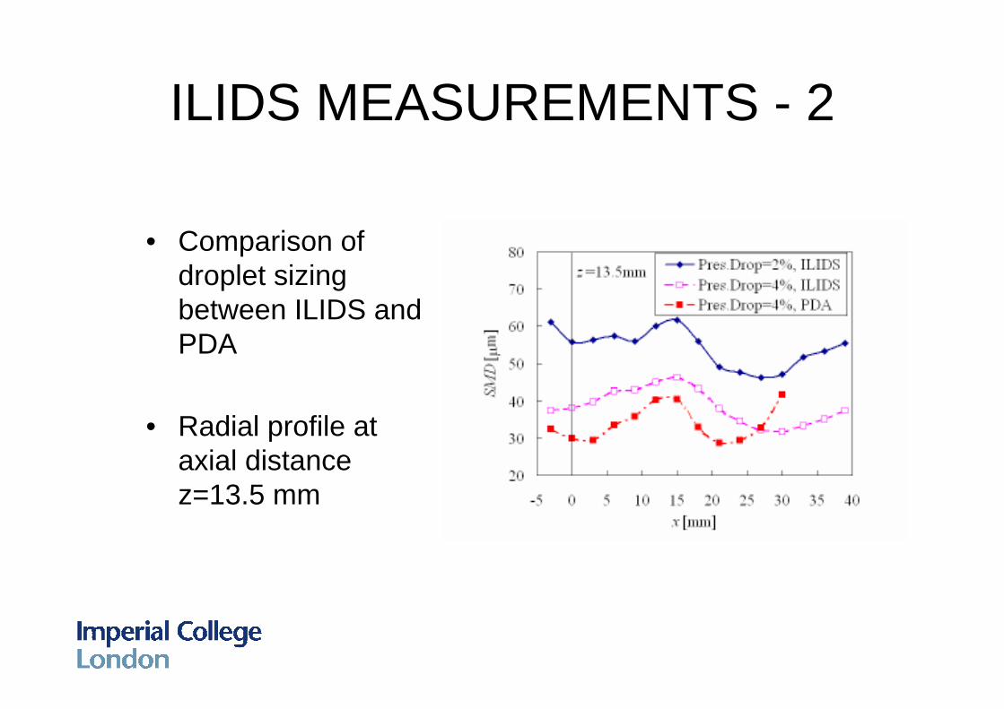
ILIDS MEASUREMENTS - 2
• Comparison of droplet sizing between ILIDS and PDA
• Radial profile at axial distance z=13.5 mm

ILIDS MEASUREMENTS - 3• Comparison of
axial droplet velocity for different sizes measured with ILIDS and PDA
• Radial profile at axial distance z=13.5 mm

Summary• Volume Fluorescence measurement of liquid intact length
and primary breakup characteristics • Shadow Doppler Velocimeter for measurements of size,
shape and velocity of non-spherical droplets / ligaments • Combined Mie/LIF for measurements in the dense spray
region. Quantification of surface area and volume of liquid, characteristics of droplet clusters and spray unsteadiness
• Interferometric Laser Imaging Droplet Sizing (ILIDS) for planar measurements of individual droplet sizes and velocities. Quantification of instantaneous spatial droplet motion, which can explain the physics of droplet cluster formation