dhanalakshmi college of engineering, chennai · dhanalakshmi college of engineering, chennai ......
TRANSCRIPT

1
DHANALAKSHMI COLLEGE OF ENGINEERING,
CHENNAI
Department of Computer Science and Engineering
CS6303 - COMPUTER ARCHITECTURE
Anna University 2 & 16 Mark Questions & Answers
Year / Semester: II / III
Regulation: 2013
Academic year: 2017 - 2018

2
UNIT-I
Part- A
1. What are the eight great ideas in computer architecture?
The eight great ideas in computer architecture are:
1. Design for Moore’s Law
2. Use Abstraction to simplify design
3. Make the common case fast
4. Performance via parallelism
5. Performance via pipelining
6. Performance via prediction
7. Hierarchy of memories
8. Dependability via redundancy
2. What are the five classic components of a computer? The five classic components of a computer are input, output, memory,
datapath, and control.
3. Define – ISA The Instruction Set Architecture, or simply architecture of a computer is the
interface between the hardware and the lowest-level software. It includes anything that
programmers make a binary machine language program work correctly, including
instructions, I/O devices, and so on.
4. Define – ABI Typically, the operating system will encapsulate the details of doing I/O,
allocating memory, and other low-level system functions so that application programmers
do not need to worry about such details. The combination of the basic instruction set and
the operating system interface provided for application programmers is called the
Application Binary Interface (ABI).
5. What are the advantages of network computers? Networked computers have several major advantages:
o Communication: Information is exchanged between computers at high speed.
o Resource sharing: Rather than each computer having its own I/O devices,
computers on the network can share I/O devices.
o Nonlocal access: By connecting computers over long distances, users need not be
near the computer which they are using.
6. Define – Response Time Response time is also called execution time. The total time required for the
computer to complete a task, including disk accesses, memory accesses, I/O activities,
operating system overhead, CPU execution time, and so on.
3
7. Define – Throughput Throughput or bandwidth - the total amount of work done in a given time.
8. Write the CPU performance equation. The classic CPU Performance equation in terms of instruction count (the number
of instructions executed by the program), CPI, and clock cycle time is given by:
9. If computer A runs a program in 10 seconds and computer B runs the same
program in 15 seconds, how much faster is A than B?
10. What are the basic components of performance?
The basic components of performance and units of measure are:
Components of Performance Units of measure
CPU execution time for a program Seconds for the program
Instruction count Instruction executed for the program
Clock cycles per instruction(CPI) Average number of clock cycles per instruction
Clock cycle time Seconds per clock cycle
11. Write the formula for CPU execution time for a program.

4
12. Write the formula for CPU clock cycles required for a program.
13. Define – MIPS Million Instructions Per Second (MIPS) is a measurement of program execution
speed based on the number of millions of instructions.
MIPS is computed as:
14. What are the fields in an MIPS instruction?
MIPS fields are
Where,
op: Basic operation of the instruction, traditionally called the opcode,
rs: The first register source operand,
rt: The second register source operand,
rd: The register destination operand. It gets the result of the operation,
shamt: Shift amount,
funct: Function,
15. Write an example for immediate operand. The quick add instruction with one constant operand is called add immediate or
addi. To add 4 to register $s3, we just write
16. Define – Stored Program Concept Today’s computers are built on two key principles:
1. Instructions are represented as numbers.

5
2. Programs are stored in memory to be read or written, just like data.
These principles lead to the stored-program concept. Treating instructions in the same
way as data greatly simplifies both the memory hardware and the software of computer
systems.
17. Define – Addressing Modes
Multiple forms of addressing are generically called addressing modes.
The MIPS addressing modes are :
1. Immediate addressing
2. Register addressing
3. Base or displacement addressing
4. PC-relative addressing
5. Pseudo direct addressing

6
PART B
16 Marks Questions with Answers
CS6303-COMPUTER ARCHITECTURE
UNIT-I
Part- B
1. Explain in detail, the eight ideas in computer architecture. (8 Marks)
The eight great ideas that computer architects have been invented in the last 60 years of
computer design. These ideas are so powerful they have lasted long after the first computer that
used them, with newer architects demonstrating their admiration by imitating their predecessors.
1. Design for Moore’s Law
The one constant for computer designers is rapid change, which is driven largely by
Moore’s Law. It states that integrated circuit resources double every 18–24 months. Moore’s
Law resulted from a 1965 prediction of such growth in IC capacity made by Gordon Moore, one
of the founders of Intel. As computer designs can take years, the resources available per chip can
easily double or quadruple between the start and finish of the project. Like a skeet shooter,
computer architects must anticipate where the technology will be when the design finishes rather
than design for where it starts. We use an “up and to the right” Moore’s Law graph to represent
designing for rapid change.
2. Use Abstraction to Simplify Design
Both computer architects and programmers had to invent techniques to make themselves
more productive, for otherwise design time would lengthen as dramatically as resources grew by
Moore’s Law. A major productivity technique for hardware and software is to use abstractions to
represent the design at different levels of representation; lower-level details are hidden to offer a
simpler model at higher levels. We’ll use the abstract painting icon to represent this second great
idea.

7
3. Make the Common Case Fast
Making the common case fast will tend to enhance performance better than optimizing
the rare case. Ironically, the common case is often simpler than the rare case and hence is often
easier to enhance. This common sense advice implies that you know what the common case is,
which is only possible with careful experimentation and measurement. We use a sports car as the
icon for making the common case fast, as the most common trip has one or two passengers, and
it’s surely easier to make a fast sports car than a fast minivan!
4. Performance via Parallelism
Since the dawn of computing, computer architects have offered designs that get more
performance by performing operations in parallel. We’ll see many examples of parallelism in
this book. We use multiple jet engines of a plane as our icon for parallel performance.
5. Performance via Pipelining
A particular pattern of parallelism is so prevalent in computer architecture that it merits
its own name: pipelining. For example, before fire engines, a “bucket brigade” would respond to
a fire, which many cowboy movies show in response to a dastardly act by the villain. The
townsfolk form a human chain to carry a water source to fire, as they could much more quickly
move buckets up the chain instead of individuals running back and forth. Our pipeline icon is a
sequence of pipes, with each section representing one stage of the pipeline.

8
6. Performance via Prediction
Following the saying that it can be better to ask for forgiveness than to ask for
permission, the final great idea is prediction. In some cases it can be faster on average to guess
and start working rather than wait until you know for sure, assuming that the mechanism to
recover from a mis prediction is not too expensive and your prediction is relatively accurate. We
use the fortune-teller’s crystal ball as our prediction icon.
7. Hierarchy of Memories
Programmers want memory to be fast, large, and cheap, as memory speed often shapes
performance, capacity limits the size of problems that can be solved, and the cost of memory
today is often the majority of computer cost. Architects have found that they can address these
conflicting demands with a hierarchy of memories, with the fastest, smallest, and most expensive
memory per bit at the top of the hierarchy and the slowest, largest, and cheapest per bit at the
bottom. Caches give the programmer the illusion that main memory is nearly as fast as the top of
the hierarchy and nearly as big and cheap as the bottom of the hierarchy. We use a layered
triangle icon to represent the memory hierarchy. The shape indicates speed, cost, and size: the
closer to the top, the faster and more expensive per bit the memory; the wider the base of the
layer, the bigger the memory.
8. Dependability via Redundancy

9
Computers not only need to be fast; they need to be dependable. Since any physical
device can fail, we make systems dependable by including redundant components that can take
over when a failure occurs and to help detect failures. We use the tractor-trailer as our icon, since
the dual tires on each side of its rear axles allow the truck to continue driving even when one tire
fails.
2. Explain in detail, the components of a computer system . (8 Marks)
There are five components of a computer that perform the tasks of inputting, outputting ,
processing, and storing data. Two key components of computers are input devices, such as the
microphone, and output devices, such as the speaker. As the names suggest, input feeds the
computer, and output is the result of computation sent to the user. Some devices, such as wireless
networks, provide both input and output to the computer.
The five classic components of a computer are input, output, memory, data path, and
control, with the last two sometimes combined and called the processor. The following Figure
shows the standard organization of a computer. This organization is independent of hardware
technology: you can place every piece of every computer, past and present, into one of these five
categories.
Description of the five classic components: The processor gets instructions and data from memory. Input writes data to memory, and
output reads data from memory. Control sends the signals that determine the operations of the
datapath, memory, input, and output. Input device A mechanism through which the computer is
fed information, such as a keyboard. Output device A mechanism that conveys the result of a
computation to a user, such as a display, or to another computer. (CPU) also called processor.
The active part of the computer, which contains the datapath and control and which adds

10
numbers, tests numbers, signals I/O devices to activate, and so on. Datapath is the component of
the processor that performs arithmetic operations control The component of the processor that
commands the datapath, memory, and I/O devices according to the instructions of the program.
memory The storage area in which programs are kept when they are running and that contains
the data needed by the running programs.
Memory:
Dynamic random access memory (DRAM): Memory built as an integrated circuit; it
provides random access to any location. Access times are 50 nanoseconds and cost per gigabyte
in 2012 was $5 to $10.
Cache memory A small, fast memory that acts as a buffer for a slower, larger memory.
Static random access memory (SRAM) Also memory built as an integrated circuit, but
faster and less dense than DRAM.
Instruction set architecture: Also called architecture. An abstract interface between the
hardware and the lowest-level software that encompasses all the information necessary to write a
machine language program that will run correctly, including instructions, registers, memory
access, I/O, and so on.
Primary memory: Memory used to hold programs while they are running; typically consists of
DRAM in today’s computers.
Secondary memory: Nonvolatile memory used to store programs and data between runs;
typically consists of flash memory in PMDs and magnetic disks in servers. To run identical
software.
Volatile memory: Storage, such as DRAM, that retains data only if it is receiving power.
Nonvolatile memory: A form of memory that retains data even in the absence of a power source
and that is used to store programs between runs. A DVD disk is nonvolatile
3. Explain in detail, the technologies for building processor and memory. (8 Marks)
Processors and memory have improved at an incredible rate, because computer designers
have long embraced the latest in electronic technology to try to win the race to design a better
computer.
A transistor is simply an on/off switch controlled by electricity. The integrated circuit
(IC) combined dozens to hundreds of transistors into a single chip. When Gordon Moore
predicted the continuous doubling of resources, he was predicting the growth rate of the number
of transistors per chip. To describe the tremendous increase in the number of transistors from
hundreds to millions, the adjective very large scale is added to the term, creating the abbreviation
VLSI, for very large-scale integrated circuit.
The manufacturing process for integrated circuits:

11
The manufacture of a chip begins with silicon, a substance found in sand. Because silicon
does not conduct electricity well, it is called a semiconductor. With a special chemical process, it
is possible to add materials to silicon that allow tiny areas to transform into one of three devices:
Excellent conductors of electricity (using either microscopic copper or aluminum
wire)
Excellent insulators from electricity (like plastic sheathing or glass)
Areas that can conduct or insulate under special conditions (as a switch)
Transistors fall in the last category. A VLSI circuit, then, is just billions of combinations
of conductors, insulators, and switches manufactured in a single small package. The
manufacturing process for integrated circuits is critical to the cost of the chips and hence
important to computer designers.
The process starts with a silicon crystal ingot, which looks like a giant sausage. Today,
ingots are 8–12 inches in diameter and about 12–24 inches long. An ingot is finely sliced into
wafers no more than 0.1 inches thick. These wafers then go through a series of processing steps,
during which patterns of chemicals are placed on each wafer, creating the transistors, conductors,
and insulators discussed earlier. Today’s integrated circuits contain only one layer of transistors
but may have from two to eight levels of metal conductor, separated by layers of insulators.
The chip manufacturing process:
After being sliced from the silicon ingot, blank wafers are put through 20 to 40 steps to
create patterned wafers. These patterned wafers are then tested with a wafer tester, and a map of
the good parts is made. Then, the wafers are diced into dies. The yield of good dies are then
bonded into packages and tested one more time before shipping the packaged parts to customers.
One bad packaged part was found in this final test.
Defect: A microscopic flaw in a wafer or in patterning steps that can result in the failure of the
die containing that defect.
Die: The individual rectangular sections that are cut from a wafer, more informally known as
chips.
Yield: The percentage of good dies from the total number of dies on the wafer.
12
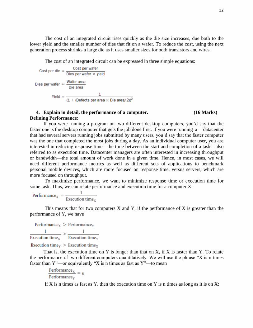
The cost of an integrated circuit rises quickly as the die size increases, due both to the
lower yield and the smaller number of dies that fit on a wafer. To reduce the cost, using the next
generation process shrinks a large die as it uses smaller sizes for both transistors and wires.
The cost of an integrated circuit can be expressed in three simple equations:
4. Explain in detail, the performance of a computer. (16 Marks)
Defining Performance:
If you were running a program on two different desktop computers, you’d say that the
faster one is the desktop computer that gets the job done first. If you were running a datacenter
that had several servers running jobs submitted by many users, you’d say that the faster computer
was the one that completed the most jobs during a day. As an individual computer user, you are
interested in reducing response time—the time between the start and completion of a task—also
referred to as execution time. Datacenter managers are often interested in increasing throughput
or bandwidth—the total amount of work done in a given time. Hence, in most cases, we will
need different performance metrics as well as different sets of applications to benchmark
personal mobile devices, which are more focused on response time, versus servers, which are
more focused on throughput.
To maximize performance, we want to minimize response time or execution time for
some task. Thus, we can relate performance and execution time for a computer X:
This means that for two computers X and Y, if the performance of X is greater than the
performance of Y, we have
That is, the execution time on Y is longer than that on X, if X is faster than Y. To relate
the performance of two different computers quantitatively. We will use the phrase “X is n times
faster than Y”—or equivalently “X is n times as fast as Y”—to mean
If X is n times as fast as Y, then the execution time on Y is n times as long as it is on X:

13
Measuring Performance:
Time is the measure of computer performance: the computer that performs the same
amount of work in the least time is the fastest. Program execution time is measured in seconds
per program. However, time can be defined in different ways, depending on what we count. The
most straightforward definition of time is called wall clock time, response time, or elapsed time.
These terms mean the total time to complete a task, including disk accesses, memory accesses,
input/output (I/O) activities, operating system overhead—everything.
CPU execution time also called CPU time: The actual time the CPU spends computing for
a specific task. user CPU time The CPU time spent in a program itself. system CPU time the
CPU time spent in the operating system performing tasks on behalf of the program.
A simple formula relates the most basic metrics (clock cycles and clock cycle time) to
CPU time:
Instruction Performance :
One way to think about execution time is that it equals the number of instructions
executed multiplied by the average time per instruction. Therefore, the number of clock cycles
required for a program can be written as
clock cycles per instruction (CPI) Average number of clock cycles per instruction for a program
or program fragment.
The Classic CPU Performance Equation:
The basic performance equation in terms of instruction count (the number of instructions
executed by the program), CPI, and clock cycle time:
or, since the clock rate is the inverse of clock cycle time:
The basic components of performance and how each is measured.
These factors are combined to yield execution time measured in seconds per program:

14
Instruction mix: A measure of the dynamic frequency of instructions across one or many
programs. The performance of a program depends on the algorithm, the language, the compiler,
the architecture, and the actual hardware.
5. Explain in detail, the MIPS instruction set. (16 Marks)
To command a computer’s hardware, you must speak its language. The words of a
computer’s language are called instructions, and its vocabulary is called an instruction set.

15
MIPS Fields:
MIPS fields are:
Here is the meaning of each name of the fields in MIPS instructions:
■ op: Basic operation of the instruction, traditionally called the opcode.
■ rs: The first register source operand.
■ rt: The second register source operand.
■ rd: The register destination operand. It gets the result of the operation.
■ shamt: Shift amount. (Section 2.6 explains shift instructions and this term; it will not be used
until then, and hence the field contains zero in this section.)
■ funct: Function. This field, often called the function code, selects the specific variant of the
operation in the op field.
MIPS instruction formats.
6. Write short notes on : i) Operations and operands ii) Representing instructions
iii) Logical and control operations (16 Marks)
i) Operations of the Computer Hardware:
Every computer must be able to perform arithmetic. The MIPS assembly language
Notation
add a, b, c
instructs a computer to add the two variables b and c and to put their sum in a.
The natural number of operands for an operation like addition is three: the two numbers
being added together and a place to put the sum. Requiring every instruction to have exactly
three operands, no more and no less, conforms to the philosophy of keeping the hardware simple:
hardware for a variable number of operands is more complicated than hardware for a fixed
number.
Three underlying principles of hardware design:
Design Principle 1: Simplicity favors regularity.
Design Principle 2: Smaller is faster.
Design Principle 3: Good design demands good compromises.
Operands of the Computer Hardware:
Unlike programs in high-level languages, the operands of arithmetic instructions are
restricted; they must be from a limited number of special locations built directly in hardware
called registers. Registers are primitives used in hardware design that are also visible to the
programmer when the computer is completed, so you can think of registers as the bricks of
computer construction. The size of a register in the MIPS architecture is 32 bits; groups of 32

16
bits occur so frequently that they are given the name word in the MIPS architecture. One major
difference between the variables of a programming language and registers is the limited number
of registers, typically 32 on current computers, like MIPS.
The reason for the limit of 32 registers is due to design principles of hardware
technology: Smaller is faster. A very large number of registers may increase the clock cycle time
simply because it takes electronic signals longer when they must travel farther.
Memory Operands:
Data transfer instruction is a command that moves data between memory and registers.
Address A value used to delineate the location of a specific data element within a memory array.
Memory addresses and contents of memory at those locations.
The data transfer instruction that copies data from memory to a register is traditionally
called load. The actual MIPS name for this instruction is lw, standing for load word.
lw $t0,8($s3) # Temporary reg $t0 gets A[8]
The instruction complementary to load is traditionally called store; it copies data from a register
to memory. The actual MIPS name is sw, standing for store word.
sw $t0,48($s3) # Stores h + A[8] back into A[12]
Load word and store word are the instructions that copy words between memory and registers in
the MIPS architecture.
Constant or Immediate Operands:
Many times a program will use a constant in an operation—for example, incrementing an
index to point to the next element of an array. This quick add instruction with one constant
operand is called add immediate or addi. To add 4 to register $s3,
Computer programs calculate both positive and negative numbers, so we need a
representation that distinguishes the positive from the negative. The most obvious solution is to
add a separate sign, which conveniently can be represented in a single bit; the name for this
representation is sign and magnitude.
Signed and Unsigned Numbers: Signed versus unsigned applies to loads as well as to arithmetic. The function of a signed
load is to copy the sign repeatedly to fill the rest of the register—called sign extension—but its
purpose is to place a correct representation of the number within that register. Unsigned loads
simply fill with 0s to the left of the data, since the number represented by the bit pattern is
unsigned.

17
ii) Representing instructions
Instructions are kept in the computer as a series of high and low electronic signals and
may be represented as numbers. In fact, each piece of an instruction can be considered as an
individual number, and placing these numbers side by side forms the instruction.
Instruction format: A form of representation of an instruction composed of fields of binary
numbers.
Machine language: Binary representation used for communication within a computer system.
Hexa decimal Numbers in base 16.
MIPS Fields:
Here is the meaning of each name of the fields in MIPS instructions:
■ op: Basic operation of the instruction, traditionally called the opcode.
■ rs: The first register source operand.
■ rt: The second register source operand.
■ rd: The register destination operand. It gets the result of the operation.
■ shamt: Shift amount. (Section 2.6 explains shift instructions and this term; it will not be used
until then, and hence the field contains zero in this section.)
■ funct: Function. This field, often called the function code, selects the specific variant of the
operation in the op field.
The compromise chosen by the MIPS designers is to keep all instructions the same length,
thereby requiring different kinds of instruction formats for different kinds of instructions. For
example, the format above is called R-type (for register) or R-format. A second type of
instruction format is called I-type (for immediate) or I-format and is used by the immediate and
data transfer instructions. The fields of I-format are
MIPS instruction encoding.
MIPS instruction formats.
iii) Logical and control operations:

18
The instructions used for the packing and unpacking of bits into words are called logical
operations.
The first class of such operations is called shift s. They move all the bits in a word to the
left or right, filling the emptied bits with 0s. For example, if register $s0 contained
0000 0000 0000 0000 0000 0000 0000 1001two = 9ten
and the instruction to shift left by 4 was executed, the new value would be:
0000 0000 0000 0000 0000 0000 1001 0000two = 144ten
The dual of a shift left is a shift right. The actual name of the two MIPS shift instructions are
called shift left logical (sll) and shift right logical (srl).
AND: A logical bit by- bit operation with two operands that calculates a 1 only if there is a 1 in
both operands. and
$t0,$t1,$t2 # reg $t0 = reg $t1 & reg $t2
OR: A logical bit-by bit operation with two operands that calculates a 1 if there is a 1 in either
operand.
or $t0,$t1,$t2 # reg $t0 = reg $t1 | reg $t2
NOT: A logical bit-by bit operation with one operand that inverts the bits; that is, it replaces
every 1 with a 0, and every 0 with a 1.
NOR: A logical bit-by bit operation with two operands that calculates the NOT of the OR of the
two operands. That is, it calculates a 1 only if there is a 0 in both operands.
Instructions for Making Decisions:
MIPS assembly language includes two decision-making instructions, similar to an if
statement with a go to. The first instruction is
beq register1, register2, L1
This instruction means go to the statement labeled L1 if the value in register1 equals the
value in register2. The mnemonic beq stands for branch if equal. The second instruction is bne
register1, register2, L1 It means go to the statement labeled L1 if the value in register1 does not
equal the value in register2. The mnemonic bne stands for branch if not equal. These two
instructions are traditionally called conditional branches.
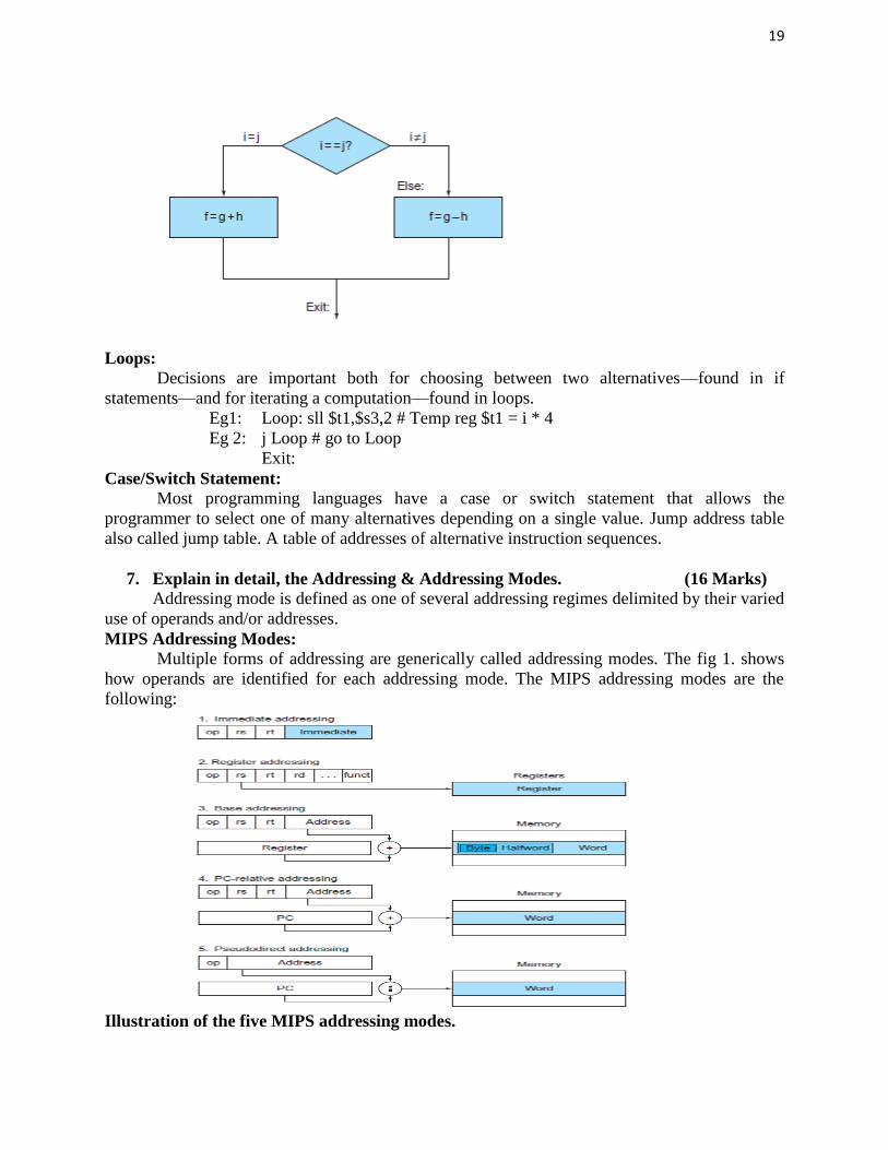
the compiled MIPS code for this C if statement if (i == j) f = g + h; else f = g – h; is given as
bne $s3,$s4,Else # go to Else if i ≠ j
conditional branch An instruction that requires the comparison of two values and that allows for
a subsequent transfer of control to a new address in the program based on the outcome of the
comparison.
19
Loops:
Decisions are important both for choosing between two alternatives—found in if
statements—and for iterating a computation—found in loops.
Eg1: Loop: sll $t1,$s3,2 # Temp reg $t1 = i * 4
Eg 2: j Loop # go to Loop
Exit:
Case/Switch Statement:
Most programming languages have a case or switch statement that allows the
programmer to select one of many alternatives depending on a single value. Jump address table
also called jump table. A table of addresses of alternative instruction sequences.
7. Explain in detail, the Addressing & Addressing Modes. (16 Marks)
Addressing mode is defined as one of several addressing regimes delimited by their varied
use of operands and/or addresses.
MIPS Addressing Modes:
Multiple forms of addressing are generically called addressing modes. The fig 1. shows
how operands are identified for each addressing mode. The MIPS addressing modes are the
following:
Illustration of the five MIPS addressing modes.

20
1. Immediate addressing, where the operand is a constant within the instruction itself
2. Register addressing, where the operand is a register
3. Base or displacement addressing, where the operand is at the memory location whose address
is the sum of a register and a constant in the instruction
4. PC-relative addressing, where the branch address is the sum of the PC and a constant in the
instruction
5. Pseudodirect addressing, where the jump address is the 26 bits of the instruction concatenated
with the upper bits of the PC.
The operands are shaded in color. The operand of mode 3 is in memory, whereas the
operand for mode 2 is a register. Note that versions of load and store access bytes, half words, or
words. For mode 1, the operand is 16 bits of the instruction itself. Modes 4 and 5 address
instructions in memory, with mode 4 adding a 16-bit address shifted left 2 bits to the PC and
mode 5 concatenating a 26-bit address shifted left 2 bits with the 4 upper bits of the PC. Note
that a single operation can use more than one addressing mode. Add, for example, uses both
immediate (addi) and register (add) addressing.
Although we show MIPS as having 32-bit addresses, nearly all microprocessors
(including MIPS) have 64-bit address extensions. These extensions were in response to the needs
of software for larger programs. The process of instruction set extension allows architectures to
expand in such a way that is able to move software compatibly upward to the next generation of
architecture.
Addressing in Branches and Jumps:
The MIPS jump instructions have the simplest addressing. They use the final MIPS
instruction format, called the J-type, which consists of 6 bits for the operation field and the rest
of the bits for the address field. Thus, j 10000 # go to location 10000 could be assembled into
this format
where the value of the jump opcode is 2 and the jump address is 10000. Unlike the jump
instruction, the conditional branch instruction must specify two operands in addition to the
branch address. Thus,
bne $s0,$s1, Exit # go to Exit if $s0 ≠ $s1
is assembled into this instruction, leaving only 16 bits for the branch address:
If addresses of the program had to fit in this 16-bit field, it would mean that no program could be
bigger than 216, which is far too small to be a realistic option today. An alternative would be to
specify a register that would always be added to the branch address, so that a branch instruction
would calculate the following:
Program counter= Register+ Branch address
PC-relative addressing is an addressing regime in which the address is the sum of the
program counter (PC) and a constant in the instruction.