dfe33b fieldbus interface - sew eurodrivelogix 1756_l71 with studio 5000 logix designer, version...
TRANSCRIPT

*25823132_0718*Drive Technology \ Drive Automation \ System Integration \ Services
Revision
DFE33B Fieldbus InterfaceEtherNet/IP™ and Modbus TCP
Edition 07/2018 25823132/EN

SEW-EURODRIVE—Driving the world

Table of contents
Revision – DFE33B Fieldbus Interface 3
Table of contents1 Revision..................................................................................................................................... 4
2 "Link/Activity" LED................................................................................................................... 5
3 Configuration and startup of EtherNet/IP™ ........................................................................... 63.1 Device description file for EtherNet/IP™ (EDS file) ........................................................ 63.2 Configuration of the EtherNet/IP™ master ..................................................................... 7
3.2.1 Starting up the DFE33B option card in the MOVIDRIVE® B drive inverter..... 73.2.2 Starting up the DFE33B option card in the MOVITRAC® B frequency inverter
or in the UOH11B gateway housing............................................................. 103.3 Device Level Ring topology .......................................................................................... 14
3.3.1 Description ................................................................................................... 143.3.2 Ring fault detection ...................................................................................... 143.3.3 Rectifying ring faults..................................................................................... 143.3.4 Hardware and software configuration .......................................................... 15
3.4 Setting the communication parameters of the MOVIDRIVE® B drive inverter ............. 163.5 Setting the communication parameters of the MOVITRAC® B frequency inverter ....... 173.6 Configuration examples ................................................................................................ 18
3.6.1 Process data exchange................................................................................ 183.6.2 Access to device parameters ....................................................................... 26
4 Timeout monitoring................................................................................................................ 36
Index ........................................................................................................................................ 37
2582
3132
/EN
– 0
7/20
18

1 Revision
Revision – DFE33B Fieldbus Interface4
1 RevisionThis revision applies to the manual "Fieldbus Interface DFE33B EtherNet/IP and Mod-bus/TCP" part number 16725611 edition 10/2008.
Replacement• The description of the Link/Activity LED in chapter 4.5 "Status LED of the
DFE33B option" is replaced by chapter 2 "'Link/Activity' LED".• Chapter 5 "Configuration and startup (EtherNet/IP)" is replaced by chapter 3 "Con-
figuration and startup of EtherNet/IP™".• A notice was added to chapter 8.3.3 "Timeout monitoring".
2582
3132
/EN
– 0
7/20
18

2"Link/Activity" LED
Revision – DFE33B Fieldbus Interface 5
2 "Link/Activity" LEDThe "Link/Activity" LEDs at the RJ45 plug connectors (X30, X32) show the status ofthe Ethernet connection.
[1]
X32
X30
25222950411
[1] "Link/Activity" LED: Status of the Ethernet connection
Status LED Operating statusGreen There is an Ethernet connection.
Yellow Data is currently being exchanged via Ethernet.
Off There is no Ethernet connection.
2582
3132
/EN
– 0
7/20
18
3 Configuration and startup of EtherNet/IP™Device description file for EtherNet/IP™ (EDS file)
Revision – DFE33B Fieldbus Interface6
3 Configuration and startup of EtherNet/IP™This chapter provides you with information on the configuration of the EtherNet/IP™master (PLC) and startup of the device for fieldbus operation.Requirements for correct configuration and startup are:• Correct connection• Correct setting of the IP address parameters of the device.Configuration is explained with examples. The examples are configurations carried outwith the programming software Studio 5000 Logix Designer by Rockwell Automation.
INFORMATIONThe figures in the sample project refer to the English version of the tool Studio 5000Logix Designer.
3.1 Device description file for EtherNet/IP™ (EDS file)
INFORMATIONA modified device description file can cause malfunctions in the device.Do not change or expand entries in the device description file. SEW‑EURODRIVEassumes no liability for malfunctions of the device caused by a modified device de-scription file.
The following device description files (EDS files) are required for proper functioning ofthe DFE33B option card:• If the option card is inserted in MOVIDRIVE® B: SEW_MOVIDRIVE_DFE33B.eds• If the option card is inserted in MOVITRAC® B or in the UOH11B gateway housing:
SEW_GATEWAY_DFE33B.eds
INFORMATIONThe latest version of the EDS file for the option can be downloaded from theSEW‑EURODRIVE homepage → www.sew‑eurodrive.com.
2582
3132
/EN
– 0
7/20
18

3Configuration and startup of EtherNet/IP™Configuration of the EtherNet/IP™ master
Revision – DFE33B Fieldbus Interface 7
3.2 Configuration of the EtherNet/IP™ masterThe following example describes configuration of the Allen Bradley controller Control-Logix 1756_L71 with Studio 5000 Logix Designer, version V24.For the Ethernet communication, a 1756-EN2TR EtherNet/IP™ interface is used.
3.2.1 Starting up the DFE33B option card in the MOVIDRIVE® B drive inverterProceed as follows:1. Start Studio 5000 Logix Designer and select the view "Controller Organizer" (tree
structure on left part of the window).2. Select the EtherNet/IP™ interface (1756-EN2TR in this case) in the folder "I/O
configuration".3. Select the command [New Module] from the context menu.
ð A module catalog is displayed.
[1]
[2]
[3]24865839243
4. Enter "DFE33B" in search field [1] and press the <Enter> key.ð If the EDS file was installed correctly, the option card is displayed in the cata-
log.5. Select "SEW-MOVIDRIVE-DFE33B" [2].
2582
3132
/EN
– 0
7/20
18

3 Configuration and startup of EtherNet/IP™Configuration of the EtherNet/IP™ master
Revision – DFE33B Fieldbus Interface8
6. Click the [Create] button [3].ð The following window is displayed.
[1] [2]
[3]
[4]
24866803851
7. In the edit box [3], enter the name of the EtherNet/IP™ device with which the dataare stored in the controller tags.
8. Enter the IP address of the EtherNet/IP™ device in the edit box [2].9. Click the button [4].
ð The following window is displayed.
24868569483 2582
3132
/EN
– 0
7/20
18

3Configuration and startup of EtherNet/IP™Configuration of the EtherNet/IP™ master
Revision – DFE33B Fieldbus Interface 9
10. Select the communication format and the process data arrangement.ð You can select up to 10 PI/PO (process input data/process output data words)
with 16 bits each.11. Click [OK].
ð The previous window opens.12. Open the tab [1].
[1] [2] [3]
15117198347
13. Enter a cycle time (data rate) in the edit box [2]. The device supports a cycle timeof a minimum of 5 ms. Longer cycle times are possible.
14. Select the connection type from the drop-down list [3]. Depending on the networkconfiguration, e.g. if a redundant master or an HMI panel is integrated in the net-work, you can either select "Unicast" or Multicast" connection.
15. Click [OK].ð The device is included in the project and the settings are adopted.
2582
3132
/EN
– 0
7/20
18

3 Configuration and startup of EtherNet/IP™Configuration of the EtherNet/IP™ master
Revision – DFE33B Fieldbus Interface10
3.2.2 Starting up the DFE33B option card in the MOVITRAC® B frequency inverter or in theUOH11B gateway housing
Proceed as follows:1. Start Studio 5000 Logix Designer and select the view "Controller Organizer" (tree
structure on left part of the window).2. Select the EtherNet/IP™ interface (1756-EN2TR in this case) in the folder "I/O
configuration".3. Select the command [New Module] from the context menu.
ð A module catalog is displayed.
[1]
[2]
[3]24868572939
4. Enter "DFE33B" in search field [1] and press the <Enter> key.ð If the EDS file was installed correctly, the option card is displayed in the cata-
log.5. Select "SEW-GATEWAY-DFE33B" [2].
2582
3132
/EN
– 0
7/20
18

3Configuration and startup of EtherNet/IP™Configuration of the EtherNet/IP™ master
Revision – DFE33B Fieldbus Interface 11
6. Click the [Create] button [3].ð The following window is displayed.
[1] [2]
[3]
[4]
24878222731
7. In the edit box [3], enter the name of the EtherNet/IP™ device with which the dataare stored in the controller tags.
8. Enter the IP address of the EtherNet/IP™ device in the edit box [2].9. Click the button [4].
ð The following window is displayed.
248685694832582
3132
/EN
– 0
7/20
18

3 Configuration and startup of EtherNet/IP™Configuration of the EtherNet/IP™ master
Revision – DFE33B Fieldbus Interface12
10. Select the communication format and the process data arrangement.ð You can select up to 24 PI/PO (process input data/process output data words)
with 16 bits each.11. Click [OK].
ð The previous window opens.12. Open the tab [1].
[1] [2] [3]
15117198347
13. Enter a cycle time (data rate) in the edit box [2]. The device supports a cycle timeof a minimum of 5 ms. Longer cycle times are possible.
14. Select the connection type from the drop-down list [3]. Depending on the networkconfiguration, e.g. if a redundant master or an HMI panel is integrated in the net-work, you can either select "Unicast" or Multicast" connection.
15. Click [OK].ð The device is included in the project and the settings are adopted.
2582
3132
/EN
– 0
7/20
18

3Configuration and startup of EtherNet/IP™Configuration of the EtherNet/IP™ master
Revision – DFE33B Fieldbus Interface 13
Startup of the DFE33B/UOH11B gateway with auto setupThe DFE33B/UOH11B gateway can also be started up without engineering PC. Forthis purpose, activate the "Auto setup" function with the corresponding DIP switch.
INFORMATIONObserve that the "Auto setup" function is performed only once when the DIP switch isswitched on. The DIP switch must remain in ON position to perform startup.The "Auto setup" function can be reactivated by switching the DIP switch on and offagain.
The DFE33B/UOH11B gateway searches for drive inverters on the subordinate SBus.The drive inverters must have different SBus addresses. SEW‑EURODRIVE recom-mends assigning the SBus addresses (parameters P881 SBus address) beginningwith address 1 in ascending order based on the arrangement of drive inverters in thecontrol cabinet. A total of up to 8 drive inverters is taken into account.The search is indicated by a brief flashing of the LED "H1" (system error). The LED"H1" remains lit if no drive inverter is detected.The process image on the fieldbus side is expanded by 3 process data words for eachdetected drive inverter. The DFE33B/UOH11B gateway cyclically exchanges 3 pro-cess data words with each connected drive inverter. The process output data is takenfrom the fieldbus, divided into blocks of three and transmitted. The drive inverter readsthe process input data, puts them together and transfers them to the fieldbus master.The cycle time of the SBus communication is 2 ms per station at a SBus baud rate of500 kBit/s without any additional engineering activities. For an application with 8 driveinverters on the SBus, the cycle time for the process data update will be8 × 2 ms = 16 ms.
INFORMATIONPerform auto setup again if you change the process data configuration of the connec-ted drive inverters since the DFE33B/UOH11B gateway stores these values onlyonce.
2582
3132
/EN
– 0
7/20
18

3 Configuration and startup of EtherNet/IP™Device Level Ring topology
Revision – DFE33B Fieldbus Interface14
3.3 Device Level Ring topology3.3.1 Description
INFORMATIONThe device supports announce telegrams only. Beacon telegrams on the fieldbus areignored and just forwarded by the device.
If a Device Level Ring topology (DLR topology) is used, 2 new telegrams are shownon the fieldbus. Both telegrams can be used to detect single fault locations in the ring.• Announce telegrams are sent cyclically every 1 s.
No special hardware of the ring components is required to process the announcetelegrams.The device supports announce telegrams only.
• The beacon telegrams are sent cyclically every 400 μs by the ring supervisor.A special hardware of the devices in the ring is required to process the beacontelegrams.The beacon telegrams are ignored and just forwarded by the device.
3.3.2 Ring fault detectionIf Beacon telegrams that are sent to the first port of the ring supervisor are not re-ceived by the second port of the ring supervisor, the ring supervisor detects a ringfault.If the telegrams do not run through the entire ring, the ring supervisor sends a non-cyclical announce telegram. This non-cyclical announce telegram leads to a statuschange of the EtherNet/IP™ interface. The network is automatically restored.
INFORMATIONUse less than 50 ring nodes in one DLR network. If more than 50 nodes are used inone DLR network, you have to consider the following:• The risk of faults in the DLR network increases.• The times for fault rectification in a faulty DLR network increase.
→ If your application requires more than 50 modes, Rockwell Automation recom-mends to split up the nodes in separate but linked DLR networks.1)
1) See user guideline by Rockwell Automation "EtherNet/IP Embedded Switch Technology – Linear andDevice-level Ring Topologies", Appendix A
3.3.3 Rectifying ring faultsIf a single fault location in the ring causes a fault and the rectification takes longer thanthe fieldbus timeout interval, you can increase the fieldbus timeout (timeout interval)by increasing the cycle time.The timeout interval of the device is calculated as follows:
T RPITimeout = × 32
TTimeout Timeout interval (fieldbus timeout) in ms 2582
3132
/EN
– 0
7/20
18

3Configuration and startup of EtherNet/IP™Device Level Ring topology
Revision – DFE33B Fieldbus Interface 15
RPI Cycle time RPI (Requested Packet Interval) in ms
The device supports a cycle time of a minimum of 5 ms.The minimum timeout interval of the fieldbus is thus 160 ms (5 × 32).
3.3.4 Hardware and software configurationThere is no need to make any special settings in the EtherNet/IP™ interface for theconfiguration of a DLR network. All configurations are carried out in the ring super-visor.
INFORMATIONFor information on this configuration, refer to the user guideline by Rockwell Automa-tion "EtherNet/IP™ Embedded Switch Technology – Linear and Device Level RingTopologies" that is available on the Rockwell website.
2582
3132
/EN
– 0
7/20
18

3 Configuration and startup of EtherNet/IP™Setting the communication parameters of the MOVIDRIVE® B drive inverter
Revision – DFE33B Fieldbus Interface16
3.4 Setting the communication parameters of the MOVIDRIVE® B drive inverterSetting thecommunicationparametersof theMOVIDRIVE® B driveinverter
The following settings must be made for simple fieldbus operation:
24878615179
Set the P100 Setpoint source and P101 Control signal source parameters to "Field-bus" to control the MOVIDRIVE® B drive inverter via EtherNet/IP™. MOVIDRIVE® Bthen accepts the setpoints of the EtherNet/IP™ and reacts to the process output dataof the higher-level controller. Activation of the control signal source and setpointsource "Fieldbus" is signaled to the higher-level controller by MOVIDRIVE® B usingthe "PO data enabled" bit 2 in the status word.The parameters of the MOVIDRIVE® B drive inverters can be set straight away viaEtherNet/IP™ without any further settings once the option card has been installed. Forexample, all parameters can be set by the higher-level controller after power-on.For safety reasons, you must also enable MOVIDRIVE® B at the terminals for controlvia the EtherNet/IP™. Therefore, you must wire and program the input terminals of theMOVIDRIVE® B accordingly. The simplest way is to wire the input terminal DI 00(function “/controller inhibit") with a +24 V signal and to program the other input termin-als DI 01 – DI 07 to "no function".
2582
3132
/EN
– 0
7/20
18

3Configuration and startup of EtherNet/IP™Setting the communication parameters of the MOVITRAC® B frequency inverter
Revision – DFE33B Fieldbus Interface 17
3.5 Setting the communication parameters of the MOVITRAC® B frequencyinverter
Setting thecommunicationparametersof theMOVITRAC® Bfrequencyinverter
The following settings must be made for simple fieldbus operation:
24888808331
Set the P100 Setpoint source and P101 Control signal source parameters to "SBus" tocontrol the MOVITRAC® B frequency inverter via EtherNet/IP™. MOVITRAC® B thenaccepts the setpoints of the DFE33B/UOH11B gateway and reacts to the process out-put data of the higher-level controller. Activation of the control signal source and set-point source "SBus" is signaled to the higher-level controller by MOVITRAC® B usingthe "PO data enabled" bit 2 in the status word.It is necessary to set the P883 SBus timeout interval parameter to a value other than0 ms for the MOVITRAC® B inverter to stop if faulty SBus communication occurs.SEW‐EURODRIVE recommends to select a value in the range between 50 and 200ms.Set a value in the range between 1 and 8 in ascending order for the parameter P881SBus address. The SBus address "0" is used by the DFE33B/UOH11B gateway andtherefore must not be used.For safety reasons, you must also enable MOVITRAC® B at the terminals for controlvia the EtherNet/IP™. Therefore, you must wire and program the input terminals of theMOVITRAC® B accordingly. The simplest way is to wire the input terminal DI 01 (func-tion "CW/Stop") with a +24 V signal and to program the other input terminals to "nofunction".
2582
3132
/EN
– 0
7/20
18

3 Configuration and startup of EtherNet/IP™Configuration examples
Revision – DFE33B Fieldbus Interface18
3.6 Configuration examples3.6.1 Process data exchange
The following example describes the configuration of the process data exchangebetween an EtherNet/IP™ master (PLC) and the device in Studio 5000 Logix De-signer, version V24.
Configuring the process data exchange in the MOVIDRIVE® B application inverterProceed as follows:1. Start up the MOVIDRIVE® B drive inverter.2. Set the IP address parameter of the DFE33B option card.3. Set the communication parameters of the MOVIDRIVE® B (see chapter "Setting
the communication parameters of the MOVIDRIVE® B drive inverter" (→ 2 16)).4. Include MOVIDRIVE® B in the configuration for the "I/O Configuration" in Studio
5000 Logix Designer (see chapter "Starting up the DFE33B option card in theMOVIDRIVE® B drive inverter" (→ 2 7)).
5. Create a user-defined data type. It allows you to organize the process data in astructure and simplifies access to the data elements.
24948940299 2582
3132
/EN
– 0
7/20
18

3Configuration and startup of EtherNet/IP™Configuration examples
Revision – DFE33B Fieldbus Interface 19
ð You can access the process data interface with explicit variable names with thecreated data type.
24948948363
6. To enable process data exchange between MOVIDRIVE® B and the higher-levelcontroller, insert CPS instructions at the beginning of the MainRoutine. The lengthdesignation in the CPS instructions depends on the data type of the destination.ð During copying of the data in the user-defined data structure (from
MOVIDRIVE® B to the controller), the values of a structure are copied.ð During copying of the data from the user-defined data structure to the output
data (from the controller to the MOVIDRIVE® B), 10 words (INT) are copied.
2582
3132
/EN
– 0
7/20
18

3 Configuration and startup of EtherNet/IP™Configuration examples
Revision – DFE33B Fieldbus Interface20
24950560779
24950556811
7. Save the project and transfer it to the controller.
2582
3132
/EN
– 0
7/20
18

3Configuration and startup of EtherNet/IP™Configuration examples
Revision – DFE33B Fieldbus Interface 21
8. Switch to RUN mode of the controller.
24975596171
9. Check if the process data correspond to the following values:ð To the values that are displayed in the parameter tree of the
MOVITOOLS® MotionStudio engineering software.
248921689712582
3132
/EN
– 0
7/20
18

3 Configuration and startup of EtherNet/IP™Configuration examples
Revision – DFE33B Fieldbus Interface22
Configuring the process data exchange in the MOVITRAC® B frequency inverter via DFE33B/UOH11Agateway
Proceed as follows:1. Start up the MOVITRAC® B frequency inverter.2. Set the IP address parameter of the DFE33B option card.3. Set the communication parameters of the MOVITRAC® B (see chapter "Setting the
communication parameters of the MOVITRAC® B frequency inverter" (→ 2 17)).4. To configure the data mapping to the drives, start up the DFE33B/UOH11B gate-
way using auto setup (see chapter "Startup of the DFE33B/UOH11B gateway withauto setup" (→ 2 13)).
5. Include MOVITRAC® B in the configuration for the "I/O Configuration" in Studio5000 Logix Designer (see chapter "Starting up the DFE33B option card in theMOVITRAC® B frequency inverter or in the UOH11B gateway housing" (→ 2 10)).
6. Create a user-defined data type. It allows you to organize the process data in astructure and simplifies access to the data elements.
24951302411
ð You can access the process data interface with explicit variable names with thecreated data type.
2582
3132
/EN
– 0
7/20
18
3Configuration and startup of EtherNet/IP™Configuration examples
Revision – DFE33B Fieldbus Interface 23
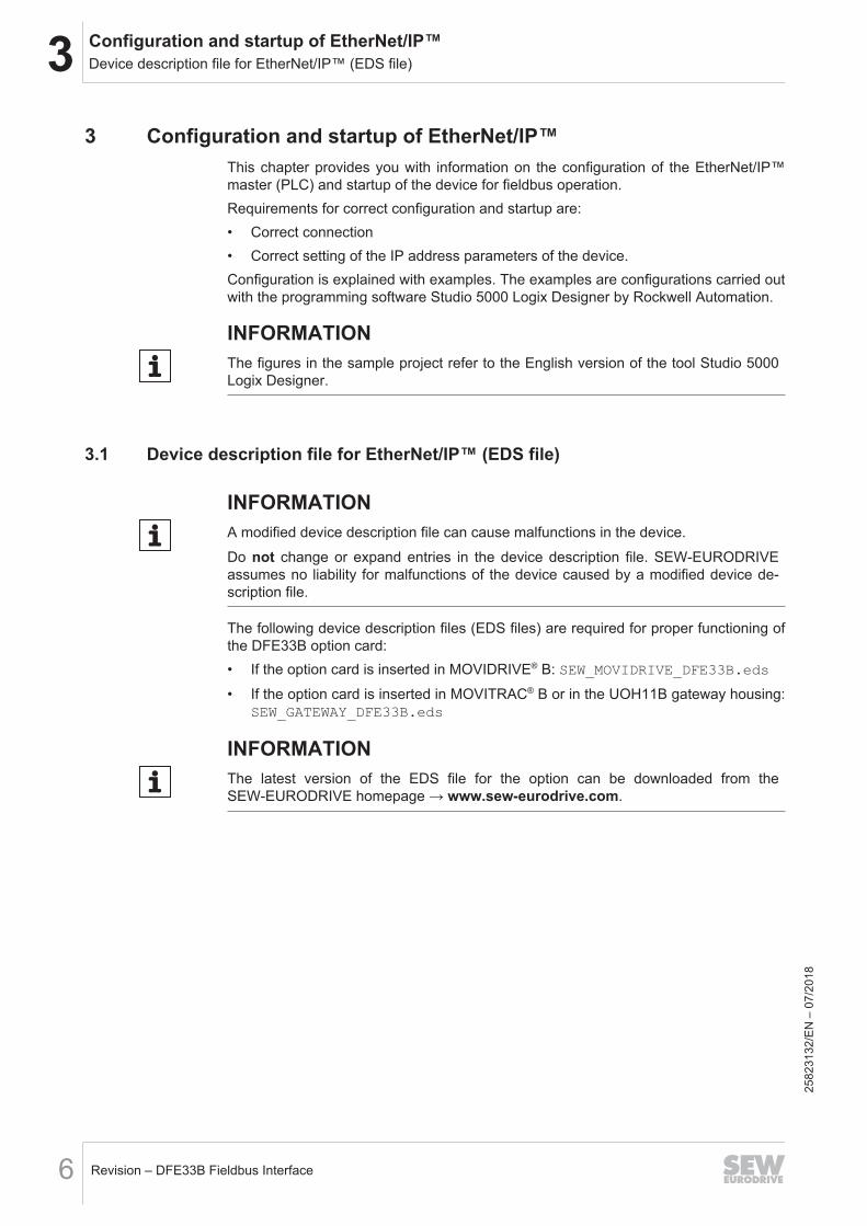
24951295243
7. To enable consistent copying of the process data image of the MOVITRAC® B tothe higher-level controller, insert CPS instructions at the beginning of the Main-Routine. The length designation in the CPS instructions depends on the data typeof the destination.ð During copying of the data in the user-defined data structure (from the gateway
to the controller), the values of a structure are copied.ð During copying of the data from the user-defined data structure to the output
data (from the controller to the gateway), 3 words (INT) are copied.
249513381232582
3132
/EN
– 0
7/20
18
3 Configuration and startup of EtherNet/IP™Configuration examples
Revision – DFE33B Fieldbus Interface24
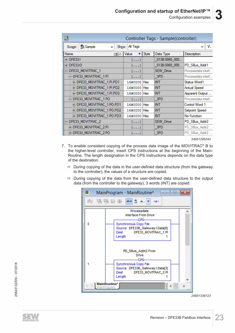
24951297931
INFORMATIONNote that the structure SEW_Gateway_DFE33B:I.Data and SEW_Gate-way_DFE33B:O.Data contain the process data of all drives at the DFE33B/UOH11Agateway. This means the 3 process data words of each drive have to be copied fromthe structure beginning with a certain offset ([0], [3] ... [21])
8. Save the project and transfer it to the controller.
2582
3132
/EN
– 0
7/20
18
3Configuration and startup of EtherNet/IP™Configuration examples
Revision – DFE33B Fieldbus Interface 25
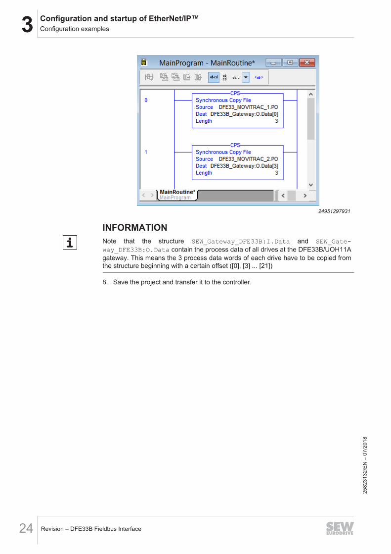
9. Switch to RUN mode of the controller.
24975601931
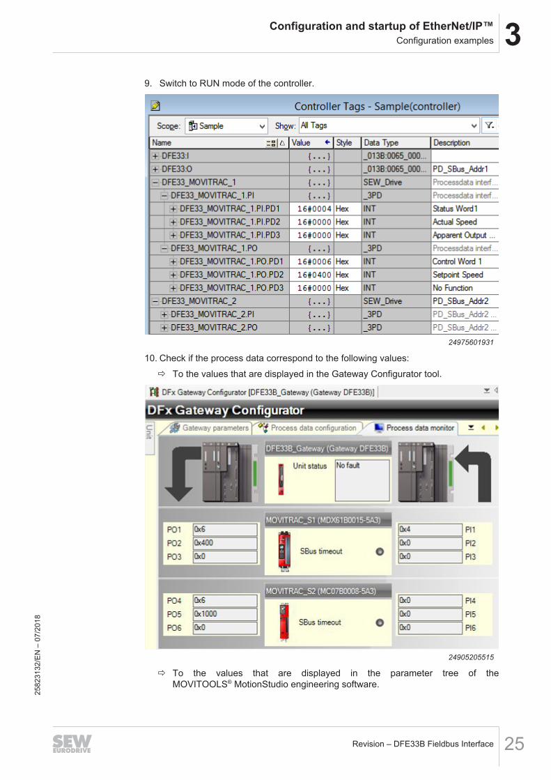
10. Check if the process data correspond to the following values:ð To the values that are displayed in the Gateway Configurator tool.
24905205515
ð To the values that are displayed in the parameter tree of theMOVITOOLS® MotionStudio engineering software.
2582
3132
/EN
– 0
7/20
18

3 Configuration and startup of EtherNet/IP™Configuration examples
Revision – DFE33B Fieldbus Interface26
24904848651
3.6.2 Access to device parametersThe 12-byte MOVILINK® parameter channel enables access to all parameters, regard-less of the bus in use. The 12-byte MOVILINK® parameter channel consists of the fol-lowing elements:
Subchannel 1Data ReservedSubindex Subaddress 1Index Subaddress 2 Subchannel 2
15214071179
For MOVIDRIVE® B and MOVITRAC® B with EtherNet/IP™ interface, the routing in-formation Subaddress 1 and Subchannel 1 are used. The device parameter can onlybe addressed with index and subindex. The routing information Subaddress 2 andSubchannel 2 are not used.The routing information has the following values:
Routing information ValueDFE33B + MOVIDRIVE® B Gateway
DFE33B/UOH11B +MOVITRAC® B
Subaddress 1 0 1
Subchannel 1 0 2
Subaddress 2 0 0
Subchannel 2 0 0
The following examples describe the configuration of the read and write access to thedevice parameters of the MOVIDRIVE® B application inverter with DFE33B optioncard with Studio 5000 Logix Designer, version V24. Differences from theMOVITRAC® B frequency inverter with DFE33B/UOH11A gateway are indicated.You can access the device parameters via CIP message service.
2582
3132
/EN
– 0
7/20
18

3Configuration and startup of EtherNet/IP™Configuration examples
Revision – DFE33B Fieldbus Interface 27
Parameter, readingProceed as follows:1. Create the user-defined data type SEW_ParameterChannel. It allows you to or-
ganize the process data in a structure and simplifies access to the data elements.
INFORMATIONTo ensure proper operation of the parameter channel, you must not change the orderof the variables. The data types must match the figure.
9007214470249995
2. Create the following controller tags:
Name Data structureReadParameter_Start BOOL
ReadParameter_Response SEW_ParameterChannel
ReadParameter_Request SEW_ParameterChannel
ReadParameter_Data DINT
ReadParameter MESSAGE
3. To be able to perform the read request, adapt the program of the controller as fol-lows:
9007214470308491
2582
3132
/EN
– 0
7/20
18

3 Configuration and startup of EtherNet/IP™Configuration examples
Revision – DFE33B Fieldbus Interface28
4. Click the button in the MSG block.ð The following window is displayed.
[1]
15215569931
5. Make the following settings in the specified sequence.
Window element Setting/valueSource Element ReadParameter_Request.Index
Source Length (Bytes) 12
Destination Element ReadParameter_Response.Index
Service Code (Hex) 34
Class (Hex) 65
Instance 0
Attribute (Hex) 025
8231
32/E
N –
07/
2018

3Configuration and startup of EtherNet/IP™Configuration examples
Revision – DFE33B Fieldbus Interface 29
6. Open the tab [1].[1]
[2]
[3]
24974144907
7. Click the button [2].ð A module manager is displayed.
8. Via "I/O configuration" > "Ethernet", select the target device with which you want toestablish communication.
9. Do not activate the check box [3]. Both the controller and the device allow only alimited number of connections.
10. Add the following additional "COP" command to the controller program. The "COP"command copies both INT variables ReadParameter_Request.Data_LOW andReadParameter_Request.Data_HIGH to the DINT variable ReadPara-meter_Data:
9007214470315787
2582
3132
/EN
– 0
7/20
18

3 Configuration and startup of EtherNet/IP™Configuration examples
Revision – DFE33B Fieldbus Interface30
11. Save the project and transfer it to the controller.12. Enter the following controller tags values:
24974152203
Controller tag ValueMOVIDRIVE® B MOVITRAC® B
ReadParameter_Start 1 1
ReadParameter_Request.Index Index of the para-meter to be read
Index of the para-meter to be read
ReadParameter_Request.SubAddress 1 0 1
ReadParameter_Request.SubChannel 1 0 2
ReadParameter_Request.SubAddress 2 0 0
ReadParameter_Request.SubChannel 2 0 0
13. Switch to RUN mode of the controller.ð The read request is executed once.ð If the read request is answered, the controller tag ReadParameter_Re-
sponse.Index displays the read index. The controller tags ReadPara-meter_Response.Data_LOW and ReadParameter_Response.Data_HIGHcontain the low word and high word of the read data. The actual data is shownin the ReadParameterResponse.Data controller tag.
ð In this example, the value (3000 min-1) of the parameter P302 maximum speed(Index 8517.0) was read.
2582
3132
/EN
– 0
7/20
18

3Configuration and startup of EtherNet/IP™Configuration examples
Revision – DFE33B Fieldbus Interface 31
14. Check if the process data correspond to the values that are displayed in the para-meter tree of the MOVITOOLS® MotionStudio engineering software.
24974155915
ð The tooltip displays index, subindex, factor, etc. of the parameter.
Writing parametersProceed as follows:1. Create the user-defined data type SEW_ParameterChannel. It allows you to or-
ganize the process data in a structure and simplifies access to the data elements.
INFORMATIONTo ensure proper operation of the parameter channel, you must not change the orderof the variables. The data types must match the figure.
9007214470249995
2. Create the following controller tags:
Name Data structureWriteParameter_Start BOOL
WriteParameter_Response SEW_ParameterChannel
WriteParameter_Request SEW_ParameterChannel
2582
3132
/EN
– 0
7/20
18

3 Configuration and startup of EtherNet/IP™Configuration examples
Revision – DFE33B Fieldbus Interface32
Name Data structureWriteParameter_Data DINT
WriteParameter MESSAGE
3. To be able to perform the write request, adapt the program of the controller as fol-lows:
9007214470335883
4. Click the button in the MSG block.ð The following window is displayed.
[1]
15215597323
5. Make the following settings in the specified sequence.
Window element Setting/valueSource Element WriteParameter_Request.Index
Source Length (Bytes) 12
Destination Element WriteParameter_Response.Index
Service Code (Hex) 35
Class (Hex) 65
Instance 0
Attribute (Hex) 0
2582
3132
/EN
– 0
7/20
18

3Configuration and startup of EtherNet/IP™Configuration examples
Revision – DFE33B Fieldbus Interface 33
6. Open the tab [1].[1]
[2]
[3]
24974683531
7. Click the button [2].ð A module catalog is displayed.
8. Via "I/O configuration" > "Ethernet", select the target device with which you want toestablish communication.
9. Do not activate the check box [3]. Both the controller and the device allow only alimited number of connections.
10. Add the following additional COP command to the controller program:ð The COP command copies the DINT variable "WriteParameter_Data to the
INT variables "WriteParameter_Request.Data_LOW and WritePara-meter_Request.Data_HIGH.
9007214470254859
2582
3132
/EN
– 0
7/20
18
3 Configuration and startup of EtherNet/IP™Configuration examples
Revision – DFE33B Fieldbus Interface34
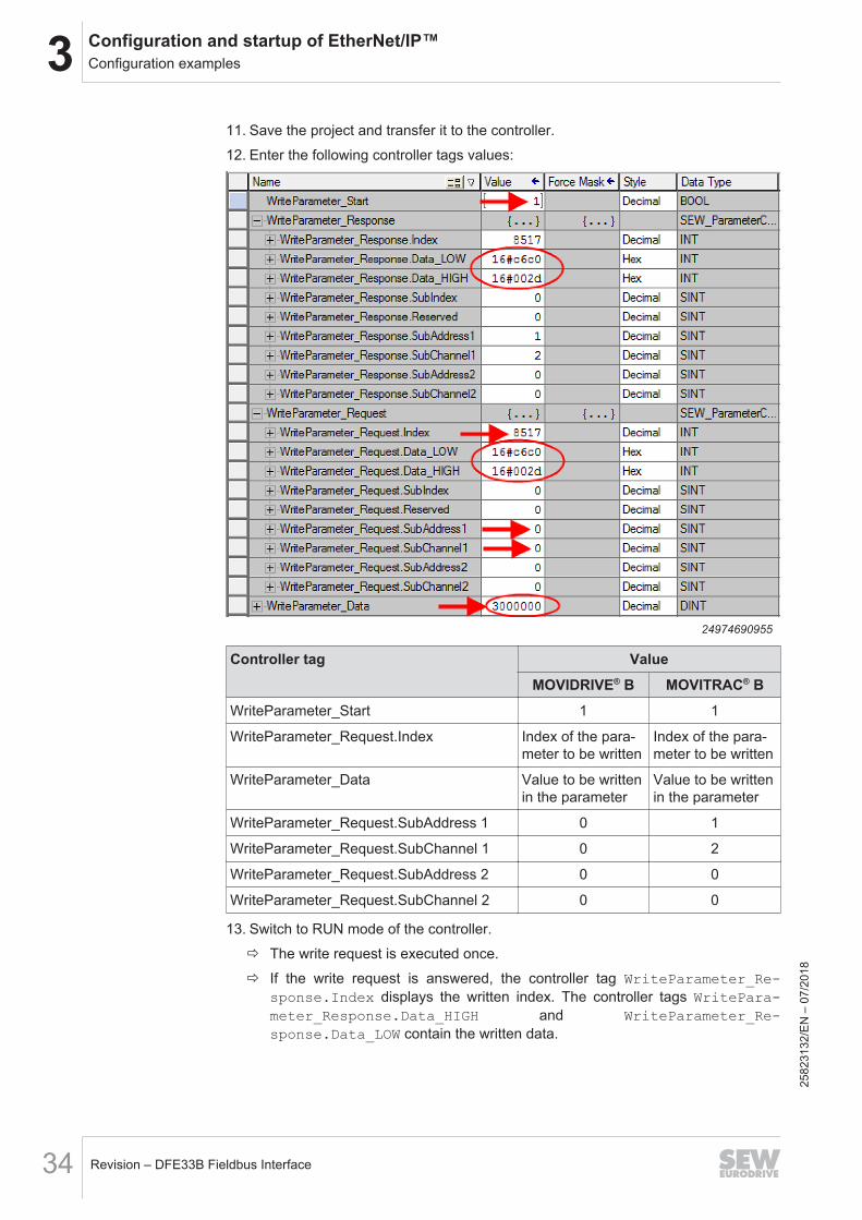
11. Save the project and transfer it to the controller.12. Enter the following controller tags values:
24974690955
Controller tag ValueMOVIDRIVE® B MOVITRAC® B
WriteParameter_Start 1 1
WriteParameter_Request.Index Index of the para-meter to be written
Index of the para-meter to be written
WriteParameter_Data Value to be writtenin the parameter
Value to be writtenin the parameter
WriteParameter_Request.SubAddress 1 0 1
WriteParameter_Request.SubChannel 1 0 2
WriteParameter_Request.SubAddress 2 0 0
WriteParameter_Request.SubChannel 2 0 0
13. Switch to RUN mode of the controller.ð The write request is executed once.ð If the write request is answered, the controller tag WriteParameter_Re-
sponse.Index displays the written index. The controller tags WritePara-meter_Response.Data_HIGH and WriteParameter_Re-sponse.Data_LOW contain the written data.
2582
3132
/EN
– 0
7/20
18

3Configuration and startup of EtherNet/IP™Configuration examples
Revision – DFE33B Fieldbus Interface 35
ð In this example, the parameter P302 maximum speed was set to 3000 min-1.14. Check if the process data correspond to the values that are displayed in the para-
meter tree of the MOVITOOLS® MotionStudio engineering software or in the PLCEditor.
2582
3132
/EN
– 0
7/20
18

4 Timeout monitoring
Revision – DFE33B Fieldbus Interface36
4 Timeout monitoring
INFORMATIONA change to the timeout interval (writing on index 8606) is activated after a re-boot.
2582
3132
/EN
– 0
7/20
18

Index
IndexA
Access to device parametersReading parameters (Studio 5000 Logix De-signer) ............................................................ 27Writing parameters (Studio 5000 Logix De-signer) ............................................................ 31
C
Configuration example EtherNet/IP™Configuring process data exchange............... 18Reading parameters (Studio 5000 Logix De-signer) ............................................................ 27Writing parameters (Studio 5000 Logix De-signer) ............................................................ 31
D
Device description fileEtherNet/IP™ ................................................... 6
Device Level Ring network, see DLR network .... 14DLR grid
Rectifying ring faults ....................................... 14Ring fault detection......................................... 14Topology......................................................... 14
DLR networkConfiguring hardware/software ...................... 15
E
EDS file, see device description file ...................... 6EtherNet/IP™
Configuration .................................................... 6Configuration examples.................................. 18Device description file ...................................... 6DLR topology.................................................. 14EDS file ............................................................ 6Startup.............................................................. 6
EtherNet/IP™ masterConfiguration with Studio 5000 Logix Designer 7
S
StartupEtherNet/IP™ ................................................... 6
Studio 5000 Logix DesignerAccessing device parameters ........................ 26Configuring EtherNet/IP™ master.................... 7Configuring process data exchange............... 18
T
Timeout time........................................................ 36
2582
3132
/EN
– 0
7/18
Revision – DFE33B Fieldbus Interface 37


SEW-EURODRIVE—Driving the world
SEW-EURODRIVE GmbH & Co KGErnst-Blickle-Str. 4276646 BRUCHSALGERMANYTel. +49 7251 75-0Fax +49 7251 [email protected]