dezurik 2-24” (50-600mm) kgc es or hd knife gate · pdf filespect the unit for damage...
TRANSCRIPT

Instruction D10411 March 2017
DeZURIK 2-24” (50-600mm) KGC ES or HD KNIFE GATE VALVES

Instructions These instructions are intended for personnel who are responsible for the installation, operation and maintenance of your KGC knife gate valve, including models KGC-ES, KGC-HD, KGC-GV, KGC-MV and KGC-SV in sizes 2-24”.
Safety Messages All safety messages in the instructions are flagged with the word Caution, Warning or Danger. These messages must be followed exactly to avoid equipment damage, personal injury or death. Safety label(s) on the product indicate hazards that can cause equipment damage, personal injury or death. If a safety label becomes difficult to see, or if a label has been removed, please contact DeZURIK for replacement.
Inspection Your KGC knife gate valve has been packaged to provide protection during shipment. Carefully in-spect the unit for damage upon arrival and file a claim with the carrier if damage is apparent.
Parts Recommended spare parts are listed on the assembly drawing. These parts should be stocked to minimize downtime. Order parts from your DeZURIK sales representative, or directly from DeZURIK. When ordering parts, please include the 7-digit part number and 4-digit revision number (example: 9999999R000) located on the data plate attached to the valve assembly. Also include the part name, the assembly drawing number, the balloon number and the quantity stated on the assembly drawing.
DeZURIK Service DeZURIK Service personnel are available to install, maintain and repair all DeZURIK products. DeZURIK also offers customized training programs and consultation services. For more information, contact your local DeZURIK representative or visit our website at www.dezurik.com.
D10411 © 2017 DeZURIK
DeZURIK 2-24” KGC ES or HD KNIFE GATE VALVES
WARNING Personnel involved in the installation or maintenance of valves should be con-stantly alert to potential emission of process material and take appropriate safety precautions. Always wear suitable protection when dealing with hazardous proc-ess materials. Handle valves which have been removed from service with the assumption of process material within the valve.

Table of Contents
Description 4
Installation 4
Operation 5
Lubrication 5
Packing 5
Adjustment 5
Drawings 6
Packing Replacement 7
Removing the Old Packing 7
Installing the New Packing 8
Reassembling the Valve 9
Seat Replacement 9
Reassembling the Valve 10
Troubleshooting 13
DeZURIK 2-24” KGC ES or HD KNIFE GATE VALVES
March 2017 Page 3 D10411
Description KGC knife gate valves have a stainless steel body and gate, and an all-metal or resilient-faced seat. The KGC knife gate valve is available in 2-48" (50-1200mm) sizes. This manual covers the 2-24” (50-600mm) sizes. A choice of several actuators and accessories is available.
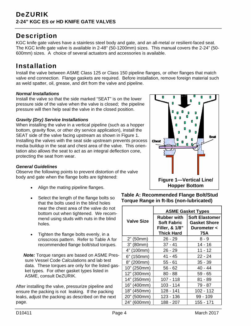
Installation Install the valve between ASME Class 125 or Class 150 pipeline flanges, or other flanges that match valve end connection. Flange gaskets are required. Before installation, remove foreign material such as weld spatter, oil, grease, and dirt from the valve and pipeline. Normal Installations Install the valve so that the side marked “SEAT” is on the lower pressure side of the valve when the valve is closed; the pipeline pressure will then help seal the valve in the closed position. Gravity (Dry) Service Installations When installing the valve in a vertical pipeline (such as a hopper bottom, gravity flow, or other dry service application), install the SEAT side of the valve facing upstream as shown in Figure 1. Installing the valves with the seat side upstream prevents process media buildup in the seat and chest area of the valve. This orien-tation also allows the seat to act as an integral deflection cone, protecting the seat from wear. General Guidelines Observe the following points to prevent distortion of the valve body and gate when the flange bolts are tightened:
Align the mating pipeline flanges. Select the length of the flange bolts so
that the bolts used in the blind holes near the chest area of the valve do not bottom out when tightened. We recom-mend using studs with nuts in the blind holes.
Tighten the flange bolts evenly, in a
crisscross pattern. Refer to Table A for recommended flange bolt/stud torques.
Note: Torque ranges are based on ASME Pres-sure Vessel Code Calculations and lab test data. These torques are only for the listed gas-ket types. For other gasket types listed in ASME, consult DeZURIK.
After installing the valve, pressurize pipeline and ensure the packing is not leaking. If the packing leaks, adjust the packing as described on the next page.
D10411 Page 4 March 2017
DeZURIK 2-24” KGC ES or HD KNIFE GATE VALVES
Valve Size
ASME Gasket Types Rubber with Soft Fabric
Filler, & 1/8” Thick Hard
Soft Elastomer Gasket Shore Durometer <
75A 2” (50mm) 26 - 29 8 - 9 3” (80mm) 37 - 41 14 - 16
4” (100mm) 26 - 29 11 - 12 6” (150mm) 41 - 45 22 - 24 8” (200mm) 55 - 61 35 - 39
10” (250mm) 56 - 62 40 - 44 12” (300mm) 80 - 88 59 - 65 14” (350mm) 107 - 118 81 - 89 16” (400mm) 103 - 114 79 - 87 18” (450mm) 128 - 141 102 - 112 20” (500mm) 123 - 136 99 - 109 24” (600mm) 188 - 207 155 - 171
Table A: Recommended Flange Bolt/Stud Torque Range in ft-lbs (non-lubricated)
Figure 1—Vertical Line/Hopper Bottom

Operation The gate in the valve is positioned by the valve actuator. The actuator moves the gate over the valve port in the closed position, and withdraws the gate from the seat in the open position. Refer to the Ac-tuator Instructions for adjustment and maintenance requirements for the actuator.
Lubrication The valve does not require lubrication. If applicable, ensure that valve threaded stems are maintained with proper lubrication. Refer to the Actuator Instructions for lubrication requirements for the actuator.
Packing The gate packing is contained and compressed by the packing gland. See Figure 2 for component identification. Note: The packing gland is slightly loosened prior to shipping. This is done to increase the life of the packing during extended storage.
Adjustment If packing leaks, tighten the adjustment nuts on top of the packing gland. Tighten the nuts evenly and gently just enough to stop the leak. Over tightening will cause excessive operating forces, and will de-crease the life of the packing.
March 2017 Page 5 D10411
DeZURIK 2-24” KGC ES or HD KNIFE GATE VALVES

Figure 2—Component Identification
D10411 Page 6 March 2017
DeZURIK 2-24” KGC ES or HD KNIFE GATE VALVES
Drawings
Removable Seat Detail
Bolt (A5) Nut (A7) Washer (A6)
Gate (A3)
Packing Gland (A4)
Packing (A2)
Packing Cord (A8) (if supplied)
Packing (A2)
Anti Extrusion Ring (A9) (if supplied)
Body (A1)
Body (A1)
Seat (A10)

Packing Replacement Removing the Old Packing
1. Relieve the pressure in the pipeline and close the valve.
2. If the actuator is powered, disconnect and lock out power to prevent accidental operation of the ac-
tuator. 3. Remove the two screws and nuts near the top of the gate and disengage the stem from the gate by
stroking the actuator (not the valve) to the open position. 4. Remove the gland nuts (A7), bolts (A5) and packing gland (A4). 5. Remove the used packing (A2), anti-extrusion ring (A9) if supplied and packing cord (A8) if sup-
plied, from the packing chamber.
March 2017 Page 7 D10411
DeZURIK 2-24” KGC ES or HD KNIFE GATE VALVES
WARNING! Pipeline pressure can cause personal injury or equipment damage. Relieve pipe-line pressure before removing gate stem and packing gland nuts.
WARNING! Accidental operation of power actuator can cause personal injury or equipment damage. Disconnect and lock out power to actuator before servicing.
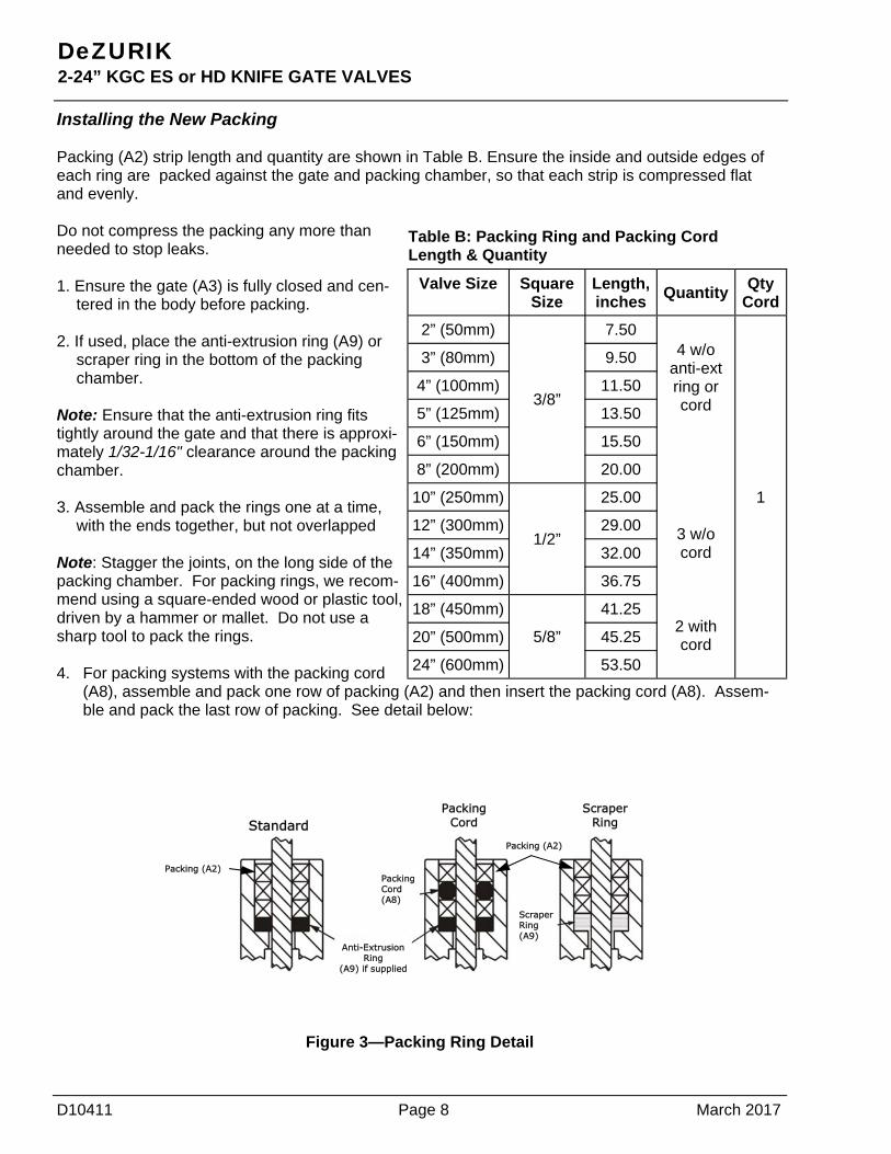
Installing the New Packing Packing (A2) strip length and quantity are shown in Table B. Ensure the inside and outside edges of each ring are packed against the gate and packing chamber, so that each strip is compressed flat and evenly. Do not compress the packing any more than needed to stop leaks. 1. Ensure the gate (A3) is fully closed and cen-
tered in the body before packing. 2. If used, place the anti-extrusion ring (A9) or
scraper ring in the bottom of the packing chamber.
Note: Ensure that the anti-extrusion ring fits tightly around the gate and that there is approxi-mately 1/32-1/16" clearance around the packing chamber. 3. Assemble and pack the rings one at a time,
with the ends together, but not overlapped Note: Stagger the joints, on the long side of the packing chamber. For packing rings, we recom-mend using a square-ended wood or plastic tool, driven by a hammer or mallet. Do not use a sharp tool to pack the rings. 4. For packing systems with the packing cord
(A8), assemble and pack one row of packing (A2) and then insert the packing cord (A8). Assem-ble and pack the last row of packing. See detail below:
Figure 3—Packing Ring Detail
D10411 Page 8 March 2017
DeZURIK 2-24” KGC ES or HD KNIFE GATE VALVES
Valve Size Square Size
Length, inches
Quantity Qty
Cord
2” (50mm)
3/8”
7.50
1
3” (80mm) 9.50
4” (100mm) 11.50
5” (125mm) 13.50
6” (150mm) 15.50
8” (200mm) 20.00
10” (250mm)
1/2”
25.00
12” (300mm) 29.00
14” (350mm) 32.00
16” (400mm) 36.75
18” (450mm)
5/8”
41.25
20” (500mm) 45.25
24” (600mm) 53.50
4 w/o anti-ext ring or cord
3 w/o cord
2 with cord
Table B: Packing Ring and Packing Cord Length & Quantity
Standard
Anti-Extrusion Ring
(A9) if supplied
Packing (A2) Packing Cord(A8)
Packing (A2)
Scraper Ring(A9)
Scraper Ring
Packing Cord

Reassembling Valve 1. Replace the packing gland (A4), bolts (A5), washer (A6) and nuts (A7). Tighten the nuts evenly
and finger tight, plus 1/2 turn.
2. Reconnect the stem to the gate with the two screws and nuts.
3. If the actuator is a powered actuator, reconnect power to the actuator.
4. Pressurize the pipeline and inspect packing for leakage.
5. If packing leaks, tighten the adjustment nuts on top of the packing gland. Tighten the nuts evenly
and gently - just enough to stop the leak. Over tightening will cause excessive operating forces,
and will decrease the life of the packing.
Replacing the Seat See Figure 2 for component identification.
1. Relieve the pressure in the pipeline and close the valve.
2. If the actuator is powered, disconnect and lock out power to prevent accidental operation of the
actuator.
3. Remove the two screws and nuts near the top of the gate and disengage the stem from the gate.
4. Remove the pipeline flange bolts and flange from the side of the valve body opposite the word
“SEAT”. As an alternative, remove both flanges, and remove the valve from the pipeline.
5. Remove the actuator yoke and actuator from the valve.
6. Remove the gland nuts (A7), washers (A6), and packing
gland (A4).
7. Remove the gate (A3) from the body.
8. Remove the packing (A2) from the packing chamber.
9. Remove the seat. Push the top of the removable seat (A10)
toward the center of the valve, and remove the seat through
the packing chamber.
10. Install the new replaceable seat:
a. Note the gate side and body side of the seat as shown in Figure 4.
b. Insert the new seat (A10) through the packing chamber.
c. Place the seat behind the lug at the 5 and 7 o‘clock positions in the body. Then push the
top of the seat into position.
March 2017 Page 9 D10411
DeZURIK 2-24” KGC ES or HD KNIFE GATE VALVES
WARNING! Pipeline pressure can cause personal injury or equipment damage. Relieve pipe-line pressure before removing gate stem and packing gland nuts.
WARNING! Accidental operation of power actuator can cause personal injury or equipment damage. Disconnect and lock out power to actuator before servicing.
Figure 4—Seat
Seat (A10)
Body (A1)

Seat Replacement Continued Reassembling the Valve 1. Reassemble the gate (A3) in the body, with the beveled edge facing away from the resilient seat.
See Figure 4.
2. Place the gate in the fully closed position.
3. Reassemble the packing, as described in “Installing New Packing”.
4. Reassemble the packing gland (A4), washers (A6), nuts (A7) and bolts (A5). Tighten the nuts evenly to finger tight, plus 1/2 turn.
5. Reassemble the yoke and actuator on the valve.
6. Reconnect the stem to the gate with the two screws and locknuts.
7. Reassemble the pipeline flange and flange bolts, or reassemble the valve in the pipeline if the valve was removed. Refer to the requirements in the “Installation” section.
8. If the actuator is a powered actuator, reconnect power to the actuator.
9. Pressurize the pipeline and inspect the valve for leaks.
10. If the packing leaks, tighten the adjustment nuts (A7) on top of the packing gland. Tighten the nuts evenly and slowly, just enough to stop the leakage. Over tightening will cause excessive operating forces, and will decrease the life of the packing.
Replacing the Gate See Figure 2 for component identification.
1. Relieve the pressure in the pipeline and close the valve.
2. If the actuator is powered, disconnect and lock out power to prevent accidental operation of the actuator.
3. Remove the pipeline flange bolts, and remove the valve from the pipeline.
4. Remove the actuator, actuator yoke, packing gland (A4), and packing (A2) from the valve.
5. Remove and inspect the gate (A3). If the gate appears to be scratched or galled due to too-long flange bolts in the chest area of the body, check for body damage in the tapped flange holes and within the chest cavity. Carefully check the seat for damage. Repair or replace the body, as appro-priate.
D10411 Page 10 March 2017
DeZURIK 2-24” KGC ES or HD KNIFE GATE VALVES
WARNING! Pipeline pressure can cause personal injury or equipment damage. Relieve pipe-line pressure before removing gate stem and packing gland nuts.
WARNING! Accidental operation of power actuator can cause personal injury or equipment damage. Disconnect and lock out power to actuator before servicing.

Gate Replacement Continued 6. Remove and inspect the seat components.
7. Replace or reinstall the seat components as described in step 10 in the “Seat Replacement “ sec-tion.
8. Place the new gate (A3) in the body, in the fully closed position.
9. Replace or reinstall the packing (A2) as described in “Installing New Packing”.
10. Replace the yoke and actuator on the valve.
11. Adjust the actuator, yoke, and packing gland so that the valve actuates smoothly full stroke in both directions, and so that there is no evidence of binding or scratching on the gate when the gate is visible in the fully open position.
12. Reinstall the valve in the pipe line —see “Installation” section.
13. If the actuator is a powered actuator, reconnect power to the actuator.
14. Pressurize the pipeline and inspect the valve for leaks.
15. If the packing leaks, tighten the adjustment nuts (A7) on top of the packing gland. Note: Tighten the nuts evenly and slowly, just enough to stop the leakage. Over tightening will cause excessive operating forces, and will decrease the life of the packing.
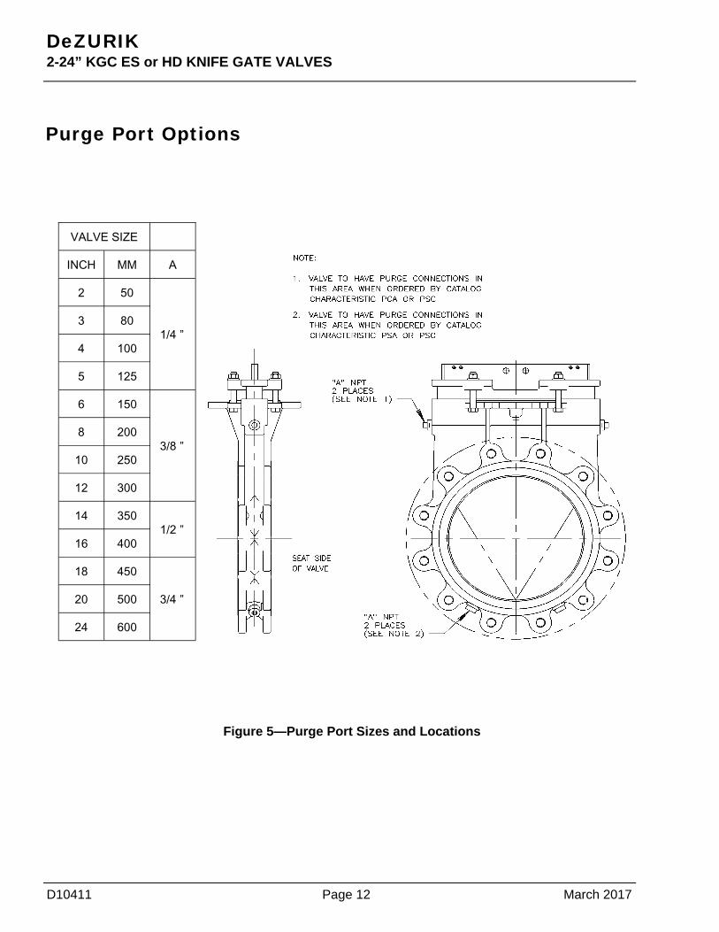
Purge Port Option When purge port options are ordered as illustrated, the intent is that the installer will connect purge lines.
Installation: 1. Remove all purge plugs after valve has been installed in line and before line is pressurized.
2. Connect proper purge line to the ports.
3. Pressurize purge lines and check for leaks.
4. Pressurize pipe line.
See Figure 5 for Purge Port sizes and locations.
March 2017 Page 11 D10411
DeZURIK 2-24” KGC ES or HD KNIFE GATE VALVES
WARNING! If pipeline is under pressure with purge port plugs in place, release line pressure before removing plugs. Serious or fatal injury may occur if not complied with.
D10411 Page 12 March 2017
DeZURIK 2-24” KGC ES or HD KNIFE GATE VALVES
Figure 5—Purge Port Sizes and Locations
Purge Port Options
INCH MM A
2 50
1/4 ” 3 80
4 100
5 125
6 150
3/8 ” 8 200
10 250
12 300
14 350 1/2 ”
16 400
18 450
3/4 ” 20 500
24 600
VALVE SIZE

Troubleshooting
Condition Possible Causes Corrective
Action
Packing is loose Adjust packing gland
Packing is worn or torn Replace packing
Packing leaks and gate is galled Packing is worn or torn Replace packing and gate, check seat for
damage
Valve leaks when fully closed, with no evidence of galling on
gate Seat is worn or torn Replace seat
Valve leaks when fully closed and gate is galled
Seat is worn or torn Replace gate and seat
Packing leaks, with no evidence of galling on gate
March 2017 Page 13 D10411
DeZURIK 2-24” KGC ES or HD KNIFE GATE VALVES

Guarantee Products, auxiliaries and parts thereof of DeZURIK, Inc. manufacture are warranted to the original purchaser for a period of twenty-four (24) months from date of shipment from factory, against defective workmanship and material, but only if properly installed, operated and ser-viced in accordance with DeZURIK, Inc. recommendations. Repair or replacement, at our option, for items of DeZURIK, Inc. manufacture will be made free of charge, (FOB) our facility with removal, transportation and installation at your cost, if proved to be defective within such time, and this is your sole remedy with respect to such products. Equipment or parts manufactured by others but furnished by DeZURIK, Inc. will be repaired or replaced, but only to the extent provided in and honored by the original manufacturers warranty to DeZURIK, Inc., in each case subject to the limitations contained therein. No claim for transportation, labor or special or consequential damages or any other loss, cost or damage shall be allowed. You shall be solely responsible for determining suitability for use and in no event shall DeZURIK, Inc. be liable in this respect. DeZURIK, Inc. does not guarantee resistance to corrosion, erosion, abrasion or other sources of failure, nor does DeZURIK, Inc. guarantee a minimum length of service. Your failure to give written notice to us of any alleged defect under this war-ranty within twenty (20) days of its discovery, or attempts by someone other than DeZURIK, Inc. or its authorized representatives to remedy the alleged defects therein, or failure to return product or parts for repair or replacement as herein provided, or failure to install and operate said products and parts according to instructions furnished by DeZURIK, Inc., or misuse, modification, abuse or alteration of such product, accident, fire, flood or other Act of God, or failure to pay entire contract price when due shall be a waiver by you of all rights under this war-ranty.
The foregoing guarantee shall be null and void if, after shipment from our factory, the item is modified in any way or a component of another manufacturer, such as but not limited to, an actuator is attached to the item by anyone other than DeZURIK, Inc. Factory Service personnel. All orders accepted shall be deemed accepted subject to this limited warranty, which shall be exclusive of any other or previous Warranty, and this shall be the only effective guarantee or warranty binding on DeZURIK, Inc., despite anything to the contrary contained in the pur-chase order or represented by any agent or employee of DeZURIK, Inc., in writing or otherwise, notwithstanding, including but not limited to implied warranties.
THE FOREGOING REPAIR AND REPLACEMENT OBLIGATIONS ARE IN LIEU OF ALL OTHER WARRANTIES, OBLIGATIONS AND LIABILITIES, INCLUDING ALL WARRANTIES OF FITNESS FOR A PARTICULAR PURPOSE OR OF MERCHANTABILITY OR OTHER-WISE, EXPRESSED OR IMPLIED IN FACT OR BY LAW, AND STATE DEZURIK, INC.’S ENTIRE AND EXCLUSIVE LIABILITY AND YOUR EXCLUSIVE REMEDY FOR ANY CLAIM IN CONNECTION WITH THE SALE AND FURNISHING OF SERVICES, GOODS OR PARTS, THEIR DESIGN, SUITABILITY FOR USE, INSTALLATION OR OPERATIONS.
Limitation of liability LIMITATION OF LIABILITY: IN NO EVENT SHALL DEZURIK, INC. BE LIABLE FOR ANY DIRECT, INDIRECT, SPECIAL OR CONSE-QUENTIAL DAMAGES WHATSOEVER, AND DEZURIK, INC.’S LIABILITY, UNDER NO CIRCUMSTANCES, WILL EXCEED THE CON-TRACT PRICE FOR THE GOODS AND/OR SERVICES FOR WHICH LIABILITY IS CLAIMED. ANY ACTION BY YOU FOR BREACH OF CONTRACT MUST BE COMMENCED WITHIN 12 MONTHS AFTER THE DATE OF SALE.
Sales and Service For information about our worldwide locations, approvals, certifications and local representative:
Web site: www.dezurik.com E-Mail: [email protected]
250 Riverside Ave. N. Sartell, Minnesota 56377 ● Phone: 320-259-2000 ● Fax: 320-259-2227
DeZURIK, Inc. reserves the right to incorporate our latest design and material changes without notice or obligation. Design features, materials of construction and dimensional data, as described in this manual, are provided for your information only
and should not be relied upon unless confirmed in writing by DeZURIK, Inc. Certified drawings are available upon request.