dewesoftx® serial com module
TRANSCRIPT

DewesoftX® Serial Com Module
SOFTWARE USER MANUAL DewesoftX® Serial Com Module V20-1
1

DewesoftX® Serial Com Module SOFTWARE USER MANUAL
1. Table of contents 1. Table of contents 2
2. About this document 6 2.1. Legend 6 2.2. Compatibility 6 2.3. Glossary and abbreviations 6 2.4. Files and Directories 8
2.4.1. Important DewesoftX® 7 Directories 9 2.4.1.1. DeweSoft Measurement Unit [recommended] 9 2.4.1.2. Windows Standard 9
2.4.2. Links 10 2.5. Licensing 10
2.5.1. Requesting an Evaluation license 10 2.5.2. Activating the Evaluation license 10
2.6. Plug-in Installation 11 2.6.1. Registering the Plug-In 11
3. General 13 3.1. Timing 13
3.1.1. Fast Data 13 3.2. Character escaping 13
3.2.1. Automatic escaping 13 3.2.2. Sequence input dialogue 14 3.2.3. ASCII Chars window 15 3.2.4. Odds and Ends 15
3.2.4.1. Decimal Separators 17 3.3. Input confirmation 18 3.4. Flow Control Settings 19
4. Serial communication control centre 20 4.1. Opening the connection 21 4.2. Transmitting requests 22 4.3. Receiving Responses 23 4.4. Main Data Grid 23
4.4.1. Time 23 4.4.2. Type 25 4.4.3. Len 26 4.4.4. Payload 26
4.4.4.1. Hex 26 4.4.4.2. Dec 26 4.4.4.3. Oct 27 4.4.4.4. Bin 27 4.4.4.5. Esc 27
4.4.5. Grouping 28
DewesoftX® Serial Com Module V20-1 2/127

DewesoftX® Serial Com Module SOFTWARE USER MANUAL
4.4.5.1. Grouping Type: None 29 4.4.5.2. Grouping Type: # of Bytes 29 4.4.5.3. Grouping Type: Separator 30 4.4.5.4. Grouping Type: Responses 30
4.5. Loading and saving data 31
5. Hardware setup 32 5.1. Devices 32
5.1.1. No Com Ports 33 5.1.2. Add/Edit Device 33
5.1.2.1. Connection settings 33 5.2. Log files 34
5.2.1 Log levels 34 5.3. Communication Delay 35
6. Channel Setup 36 6.1. Device List 36
6.1.1. Orphaned devices 36 6.2. Device Toolbar 37 6.3. Warnings and Errors 38 6.4. Default Settings 39
7. Requests 40 7.1. Requests tab-sheet 40
7.1.1. Requests: Main Toolbar 40 7.1.2.Requests Order 41
7.2. Add/Edit Request 41 7.2.1. Activation Event 42
7.2.1.1. User input 42 7.2.2. Request: Response Handling 44
7.2.2.1. Default 45 7.2.2.2. Pause After Sending 45 7.2.2.3. Custom 45 7.2.2.4. Queueing 46
7.2.3. Request: Main Toolbar 46 7.3. Request Parts 47
7.3.1. Request Parts Example 47 7.3.2. Request Part 49
7.3.2.1. BinHex Encoding 49 7.3.2.2. Use for CRC 50 7.3.2.3. Constant expressions 50 7.3.2.4. Channel data 50
7.3.3. Request Part Crc 59
8. Responses 60 8.1. Responses tab-sheet 60
DewesoftX® Serial Com Module V20-1 3/127

DewesoftX® Serial Com Module SOFTWARE USER MANUAL
8.1.1. Responses: Main Toolbar 60 8.1.2. Responses Order 61 8.1.3. Response Test 61
8.2. Add/Edit Response 61 8.2.1. Response properties 62
8.2.1.1. Name 62 8.2.1.2. Startstring 62 8.2.1.3. Expected Rate 63
8.2.2. Receive Action 63 8.2.3. Single Response Test 64 8.2.4. Response: Main Toolbar 65 8.2.5. Response: Main Data Grid 66
8.3. Response Parts 67 8.3.1. General response parts 67
8.3.1.1. Response Part: BinHex Encoding 68 8.3.1.2. Ignore response 68 8.3.1.3. Text 69 8.3.1.4. Numeric 70 8.3.1.5. Exception Handling Of Response Parts 73 8.3.1.6. Channel Properties 76
8.3.2. CRC 81 8.3.2.1. Presets 82 8.3.2.2. Check Value Settings 82 Representation 83 8.3.2.3. Check Value data 83
9. Monitoring 85 9.1. Monitoring Timeout 85
9.1.1. Add status message on timeout 85 9.2. Status Channel 85 9.3. Sent requests 86 9.4. Skipped Data Channel 86 9.5. Com Buffer Size 87 9.6. Log received data 87
10. Advanced Topics 88 10.1. Copy and Paste 88 10.2. Drag And Drop 88 10.3. Testing the Module without hardware 88
10.3.1. Null-modem emulator 88 10.3.1.1. Installation 89 10.3.1.2. Checking the Installation 90 10.3.1.3. Renaming the COM Ports 92
10.3.2. Data emulator 93 10.3.3. Test-data in DewesoftX® 97
DewesoftX® Serial Com Module V20-1 4/127

DewesoftX® Serial Com Module SOFTWARE USER MANUAL
10.4. Update to V2.1.0 100 10.4.1. CRC changes in V2.1.0 100
11. Configuration Examples 102 11.1. NMEA-0183 WIMWV 102
11.1.1. Format 102 11.1.2. Configuration 102
11.2. DMU02 Gyro & Eval board 106 11.2.1. Format 106 11.2.2. Configuration 107
11.2.2.1. Requests 107 11.2.2.2. Response 107
11.3. EPAD modules 108 11.3.1. Format 108 11.3.2. Configuration 110
11.3.2.1. Module 1: EPAD-TH8-P 110 11.3.2.2. Module 2: EPAD-V8-P 113
11.4. Analyt-MTC Massflow meter 117 11.4.1. Format 117 11.4.2. Configuration 118
12. Warranty information 119 12.1. Calibration 119 12.2. Support 119 12.3. Service/repair 119 12.4. Restricted Rights 119 12.5. Printing History 120 12.6. Copyright 120 12.7. Trademarks 120
13. Safety instructions 121 13.1. Safety symbols in the manual 121 13.2. General Safety Instructions 121
13.2.1. Environmental Considerations 121 13.2.2. Product End-of-Life Handling 121 13.2.3. System and Components Recycling 121 13.2.4. General safety and hazard warnings for all Dewesoft systems 122
14. Documentation version history 125
DewesoftX® Serial Com Module V20-1 5/127

DewesoftX® Serial Com Module SOFTWARE USER MANUAL
2. About this document
2.1. Legend The following symbols and formats will be used throughout the document.
Important It gives you important information about the subject. Please read carefully!
Hint It gives you a hint or provides additional information about a subject.
Example Gives you an example of a specific subject.
2.2. Compatibility The Module requires Dewesoft X2 ® (32-bit) or higher version of ,DewesoftX® (X3, 2020, both 32-bit and 64-bit version)
2.3. Glossary and abbreviations This glossary includes explanations of some of the most important terms and abbreviations that are used in documentation. ASCII The American Standard Code for Information Interchange (ASCII, pronunciation: /ˈæski/ ass-kee;) is a character-encoding scheme originally based on the English alphabet. ASCII codes represent text in computers, communications equipment, and other devices that use text. Most modern character-encoding schemes are based on ASCII, though they support many additional characters. Bin Binary: The binary numeral system, or base-2 number system, represents numeric values using two symbols: 0 and 1. Bit Bit, the basic unit of information storage, a single binary digit that is either 0 or 1. see also Baud (Bd) Baud (Bd) is synonymous to symbols per second per second. It is the unit of symbol rate, also known as baud rate or modulation rate; the number of distinct symbol changes.
DewesoftX® Serial Com Module V20-1 6/127

DewesoftX® Serial Com Module SOFTWARE USER MANUAL
A baud rate, by definition, means the number of times a signal in a communications channel changes state or varies.
Example A 2400 baud rate means that the channel can change states up to 2400 times per second.
This is often confused with the bit rate (expressed in bit/s), which is related, but may be different. The number of bits per baud is determined by the modulation technique.
Example If we use a baud rate of 2400,and a phase modulation (which can transmit four bits per baud), this means that we can transfer 9600 bit/s. 2400 baud x 4 bits per baud = 9600 bps
The baud rate (communication speed) between the serial device and the PC can be configured in the hardware setup of the Module (see chapter Connection settings). Dec Decimal: The decimal numeral system (also called base ten or occasionally denary) has ten as its base. It is the numerical base most widely used by modern civilizations. EPAD2 EPAD2 series modules are rugged low-speed isolation amplifiers for RS485-bus. These modules are mainly used to add multiple slow channels to dynamic data acquisition instruments. Esc Escaped representation: an escape character is used to encode special characters: An escape character is a character which invokes an alternative interpretation on subsequent characters in a character sequence. see 2.2 Character escaping on page 8 for more details. Hex In mathematics and computer science, hexadecimal (also base 16, or hex) is a positional numeral system with a radix, or base, of 16. It uses sixteen distinct symbols, most often the symbols 0–9 to represent values zero to nine, and A, B, C, D, E, F (or alternatively a–f) to represent values ten to fifteen. Hz The hertz (symbol: Hz) is the SI unit of frequency defined as the number of cycles per second of a periodic signal. IEEE 754 The IEEE Standard for Floating-Point Arithmetic (IEEE 754) is a technical standard for floating-point computation established in 1985 by the Institute of Electrical and Electronics Engineers (IEEE). LSB The Least Significant Bit is the bit position in a binary integer giving the units value, that is, determining whether the number is even or odd. The LSB is sometimes referred to as the right-most bit, due to the convention in positional notation of writing less significant digits further to the right.
DewesoftX® Serial Com Module V20-1 7/127

DewesoftX® Serial Com Module SOFTWARE USER MANUAL
NMEA-0183 is a combined electrical and data specification for communication between marine electronic devices such as echo sounder, sonars, anemometer, gyrocompass, autopilot, GPS receivers and many other types of instruments. Oct The octal numeral system, or oct for short, is the base-8 number system, and uses the digits 0 to 7. Numerals can be made from binary numerals by grouping consecutive binary digits into groups of three (starting from the right). For example, the binary representation for decimal 74 is 1001010, which can be grouped into (00)1 001 010 — so the octal representation is 112. PC DS NET systems are typically connected to a Personal Computer which runs DewesoftX® to fetch the measurement data. RS-232 Recommended Standard 232: is a standard for serial communication. It is commonly used in computer serial ports. RS-485 RS-485 is a synonym for EIA-485 which is a standard defining the electrical characteristics of drivers and receivers. Digital communications networks implementing the EIA-485 standard can be used effectively over long distances and in electrically noisy environments. Multiple receivers may be connected to such a network in a linear, multi-drop configuration. These characteristics make such networks useful in industrial environments and similar applications. Request data that is sent from DewesoftX® to the serial device Response data that the serial device sends to DewesoftX® usually as a reaction to a Request. Rx Receive – see also Response Tx Transmit – see also Request. USB Universal Serial Bus is a specification to establish communication between devices and a host controller (usually PCs).
DewesoftX® Serial Com Module V20-1 8/127
DewesoftX® Serial Com Module SOFTWARE USER MANUAL
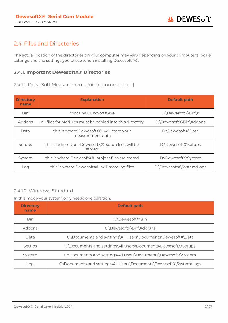
2.4. Files and Directories The actual location of the directories on your computer may vary depending on your computer's locale settings and the settings you chose when installing DewesoftX® .
2.4.1. Important DewesoftX® Directories
2.4.1.1. DeweSoft Measurement Unit [recommended]
Directory name
Explanation Default path
Bin contains DEWSoftX.exe D:\DewesoftX\Bin\X
Addons .dll files for Modules must be copied into this directory D:\DewesoftX\Bin\Addons
Data this is where DewesoftX® will store your measurement data
D:\DewesoftX\Data
Setups this is where your DewesoftX® setup files will be stored
D:\DewesoftX\Setups
System this is where DewesoftX® project files are stored D:\DewesoftX\System
Log this is where DewesoftX® will store log files D:\DewesoftX\System\Logs
2.4.1.2. Windows Standard In this mode your system only needs one partition.
Directory name
Default path
Bin C:\DewesoftX\Bin
Addons C:\DewesoftX\Bin\AddOns
Data C:\Documents and settings\All Users\Documents\DewesoftX\Data
Setups C:\Documents and settings\All Users\Documents\DewesoftX\Setups
System C:\Documents and settings\All Users\Documents\DewesoftX\System
Log C:\Documents and settings\All Users\Documents\DewesoftX\System\Logs
DewesoftX® Serial Com Module V20-1 9/127

DewesoftX® Serial Com Module SOFTWARE USER MANUAL
2.4.2. Links DewesoftX® download section https://www.dewesoft.com/download
2.5. Licensing The Module requires a valid DewesoftX® license. To test the Module you can use an Evaluation license.
2.5.1. Requesting an Evaluation license
You can request an Evaluation license from our homepage: http://www.dewesoft.com/registration (1) Click on Evaluation license (2) Fill out all the required fields (3) Click the Request license button
Image 1: Evaluation license
2.5.2. Activating the Evaluation license When you have received your trial licence key, open DewesoftX® go to Settings - Hardware Setup…, select the Registration tab sheet and enter the license code (if you already have other licenses, you may need to click the Create button).
Now enter the license code and click the Register online button.
Then your new license key will show up in the list and should have the Status Valid.
Image 2: Enter license key
Image 3: Valid trial license
DewesoftX® Serial Com Module V20-1 10/127

DewesoftX® Serial Com Module SOFTWARE USER MANUAL
2.6. Plug-in Installation Simply copy the file SerialCom.dll into the Addons folder of your DewesoftX® installation (e.g. D:\DewesoftX\Bin\Addons\). Then you can start DewesoftX® and register the Module (aka. Extension). Click Settings - Settings…, select Extensions and click the plus sign. Then find the Module in the list and activate it (i.e. click the check-box (1) in Image 4) - when the Module does not show up in the list, you may need to register it first (see the next chapter Registering the Plug-In)
Image 4: Enable Plug-In
2.6.1. Registering the Plug-In Before you can use Modules in DewesoftX® the Modules must be registered once. When DewesoftX® is started it will try to register all Modules (*.dll files) that it finds in the AddOns folder. But in order to do that, DewesoftX® requires administrator permissions (because it must write to the Windows® registry). When DewesoftX® is not with administrator permissions, the registration cannot be done automatically.
When the Module does not show up in the Extensions list, you must press the Refresh button (see (2) in Image 5). Note: you may need to start DewesoftX® as administrator (depending on the UAC settings of your Windows user/installation).
When you have pressed the Refresh button, then you will see the registration Window in Image 6 for a short time. After that, you must restart DewesoftX® .
DewesoftX® Serial Com Module V20-1 11/127

DewesoftX® Serial Com Module SOFTWARE USER MANUAL
Image 5: Extensions: Refresh button
Image 6: Registration Window
DewesoftX® Serial Com Module V20-1 12/127

DewesoftX® Serial Com Module SOFTWARE USER MANUAL
3. General 3.1. Timing The SerialCom Module will use the time when it receives the serial data for time-stamping. You could use the Communication Delay setting in the hardware setup to adjust the offset: see chapter Communication Delay.
3.1.1. Fast Data
Modules in DewesoftX® will only get a chance to read the data every now and then (usually about every 33 ms, but this can be configured in Settings…-Global Settings-General-Acquisition update rate). Since serial data is usually very slow, this is fine. But when we have a device that sends data very fast (e.g. at a rate of 1kHz), then the data in DewesoftX® would look like that in Image 7. You can see that all data was received between the time when the Module had a chance to read the data will have the same time-stamp. In such a case, the Module will wait for some more data to arrive and then evenly distribute those data-points: see Image 8. The duration how long we wait for the next data to arrive can be configured in the Hardware setup: see Data-Wait [ms] in chapter Connection setting.
Image 7: Fast Data: Multiple Points At Same Time
Image 8: Fast Data: Distributed Data-points
3.2. Character escaping Since many protocols use non-printable special characters as separators, you must escape those special characters. e.g. you cannot directly enter a carriage return into an edit field. You must use an escape sequence instead: e.g. \CR, #13, $0A For a complete list of escape sequences just open the ASCII Chars dialogue (see chapter ASCII Chars window).
3.2.1. Automatic escaping Whenever you leave an input field that supports character escaping (e.g. Startstring, Stopstring, Field Separator), the content of the field will automatically be escaped.
For example, when you enter a space character in the Prefix input field, it will look in the image below. You can see that the cursor moved a little
When you leave the input field by clicking into the next field or pressing the Tab key on your keyboard you can see that the space character
DewesoftX® Serial Com Module V20-1 13/127

DewesoftX® Serial Com Module SOFTWARE USER MANUAL
to the right, because you have entered the space character.
has automatically been escaped and you can now see the escape sequence for the space character which is: \SPC.
Image 9: Space in an input field
Image 10: Escaped Space character
You can also click the small I button (the I stands for information) to get a more comfortable view of the input:
3.2.2. Sequence input dialogue When you click the small I button (the I stands for information) to get a more comfortable view of the input (see Image 9):
Image 11: Sequence input dialogue
1. In the input dialogue you can enter or paste arbitrary text. You may need to escape special characters. The escaped version of the input string will be shown below the Input field (see 3.) 2. When you click the Use button, the escaped input (see 3) will be copied to the Input field. In the example above, you can see that the Input field (1.) shows a space character, while the escaped input (3.) shows the escape sequence \SPC for the space character. 3. Will always show the escaped version of the Input field (1.) 4. A tabular display of the current Input which makes it easy to identify each input character.
● The first row named # shows the index number of the character ● the 2nd row called ASCII shows the ASCII representation of the character or the escape sequence
(e.g. the 4th input character is the escape sequence \SPC) ● the 3rd row called Hex shows the hexadecimal representation of the character ● the 4th row called Dec shows the decimal representation of the character
5. The Info… button will open another window that shows a detailed list of all ASCII characters and their escape sequences (see chapter ASCII Chars window)
DewesoftX® Serial Com Module V20-1 14/127
DewesoftX® Serial Com Module SOFTWARE USER MANUAL
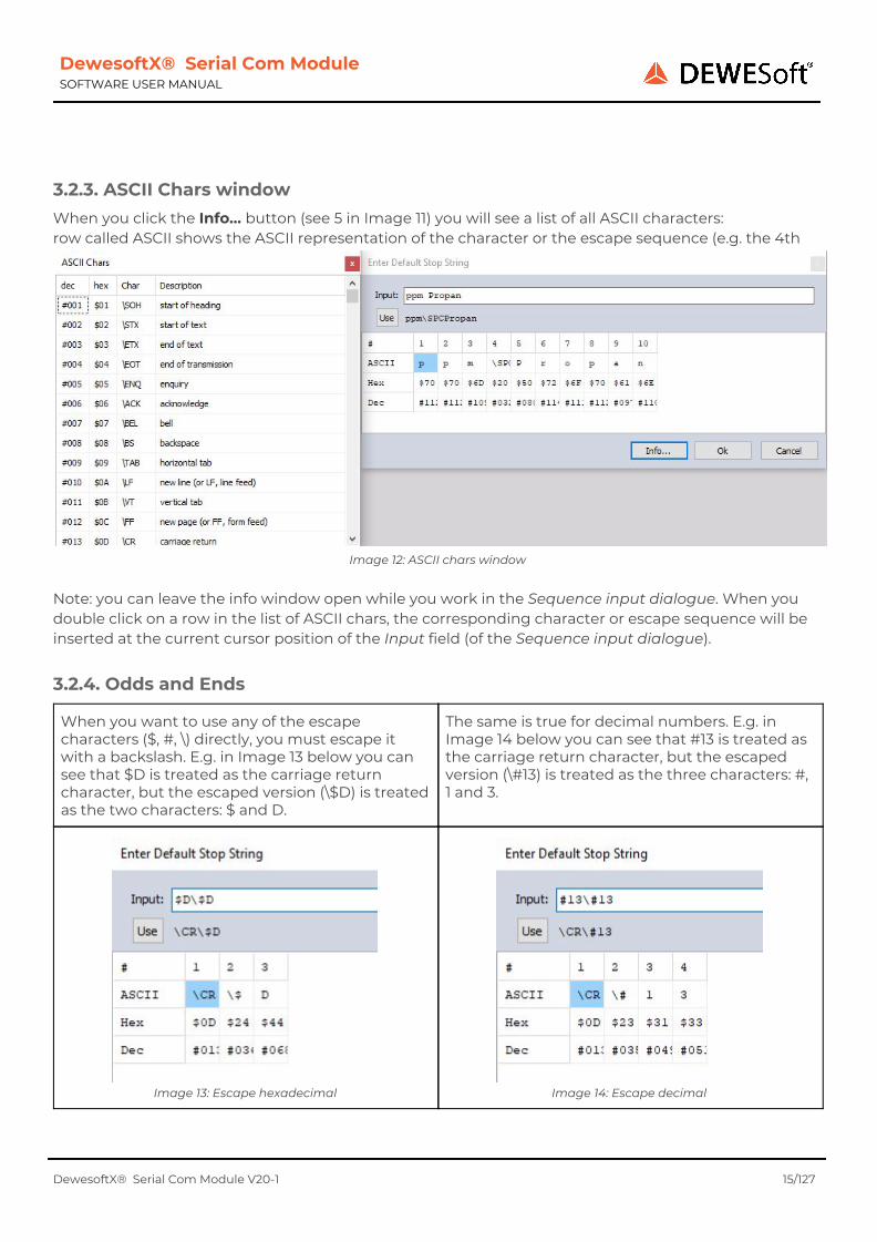
3.2.3. ASCII Chars window When you click the Info… button (see 5 in Image 11) you will see a list of all ASCII characters: row called ASCII shows the ASCII representation of the character or the escape sequence (e.g. the 4th
Image 12: ASCII chars window
Note: you can leave the info window open while you work in the Sequence input dialogue. When you double click on a row in the list of ASCII chars, the corresponding character or escape sequence will be inserted at the current cursor position of the Input field (of the Sequence input dialogue).
3.2.4. Odds and Ends
When you want to use any of the escape characters ($, #, \) directly, you must escape it with a backslash. E.g. in Image 13 below you can see that $D is treated as the carriage return character, but the escaped version (\$D) is treated as the two characters: $ and D.
The same is true for decimal numbers. E.g. in Image 14 below you can see that #13 is treated as the carriage return character, but the escaped version (\#13) is treated as the three characters: #, 1 and 3.
Image 13: Escape hexadecimal
Image 14: Escape decimal
DewesoftX® Serial Com Module V20-1 15/127

DewesoftX® Serial Com Module SOFTWARE USER MANUAL
The parser is built in a lenient way. It will always try to find matching escape sequences and if it doesn't find them the characters are used as they are. When you enter $CSV the lenient parser will try to find the best match for a hexadecimal sequence after the $. The only valid hexadecimal character that follows the $ sign is the C (S is not a valid hexadecimal char) and therefore $C is interpreted as a hexadecimal escape sequence which relates to the Formfeed ASCII character. Note: the input $0CSV would have the same result.
If you want to use $C as it is in your text, you must escape the $ sign with a backslash (see Image 16 below).
Image 15: Input $CSV
Image 16: Input: \$CSV
In Image 17 you can see that the lenient parser automatically escapes the $ sign, if the following characters form no valid hexadecimal escape sequence.
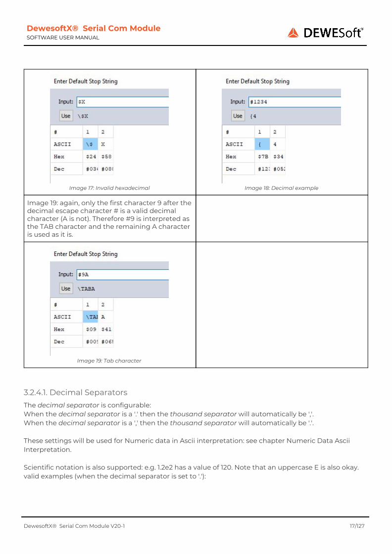
Image 18 shows an example of parsing a decimal escape sequence: only a maximum of the first 3 numbers can form the decimal escape sequence (since the highest possible ordinal value for ASCII characters is 255). Therefore the string #123 is interpreted as { character and the remaining 4 characters are used as is.
DewesoftX® Serial Com Module V20-1 16/127
DewesoftX® Serial Com Module SOFTWARE USER MANUAL
Image 17: Invalid hexadecimal
Image 18: Decimal example
Image 19: again, only the first character 9 after the decimal escape character # is a valid decimal character (A is not). Therefore #9 is interpreted as the TAB character and the remaining A character is used as it is.
Image 19: Tab character
3.2.4.1. Decimal Separators The decimal separator is configurable: When the decimal separator is a '.' then the thousand separator will automatically be ','. When the decimal separator is a ',' then the thousand separator will automatically be '.'. These settings will be used for Numeric data in Ascii interpretation: see chapter Numeric Data Ascii Interpretation. Scientific notation is also supported: e.g. 1.2e2 has a value of 120. Note that an uppercase E is also okay. valid examples (when the decimal separator is set to '.'):
DewesoftX® Serial Com Module V20-1 17/127
DewesoftX® Serial Com Module SOFTWARE USER MANUAL
Data Note
1 integer value of 1
1. integer value of 1 (trailing decimal separator is okay)
1,234.56 floating point value of 1234.56 (thousand separator is ignored)
1.23456e2 scientific notation – value is 123.456
-2 minus 2
-2. minus 2 (trailing decimal separator is okay)
-1.4e-1 scientific notation – value is: -0.14
3.3. Input confirmation
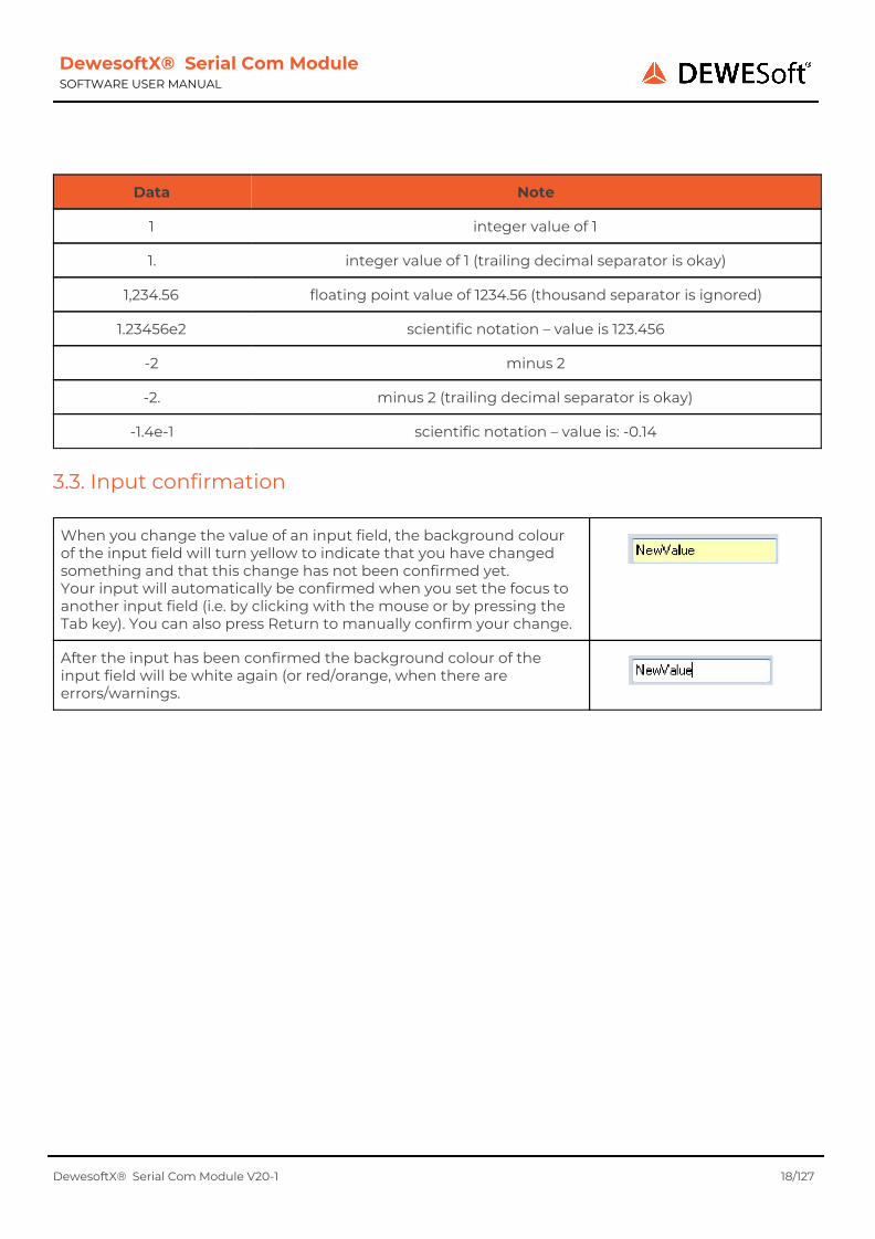
When you change the value of an input field, the background colour of the input field will turn yellow to indicate that you have changed something and that this change has not been confirmed yet. Your input will automatically be confirmed when you set the focus to another input field (i.e. by clicking with the mouse or by pressing the Tab key). You can also press Return to manually confirm your change.
After the input has been confirmed the background colour of the input field will be white again (or red/orange, when there are errors/warnings.
DewesoftX® Serial Com Module V20-1 18/127

DewesoftX® Serial Com Module SOFTWARE USER MANUAL
3.4. Flow Control Settings
Usually the default flow control settings are fine. But for some older devices it may be necessary to configure special settings. e.g. the settings in Image 20 show the required settings for a HBM UGR-60 device. Flow control can be performed either by control signal lines (hardware), or by reserving in-band control characters (software) to signal flow start and stop (such as the ASCII codes for XON/XOFF). In common RS 232 there are pairs of control lines which are usually referred to as hardware flow control:
● RTS (Request To Send) and CTS (Clear To Send), used in RTS flow control
● DTR (Data Terminal Ready) and DSR (Data Set Ready), used in DTR flow control
The XOFF character has value 19; XON has value 17.
Image 20: Flow Control Settings
See also: chapter Connection settings For more information on flow control see:
● http://en.wikipedia.org/wiki/Serial_port#Flow_control ● http://en.wikipedia.org/wiki/Flow_control_(data)
DewesoftX® Serial Com Module V20-1 19/127
DewesoftX® Serial Com Module SOFTWARE USER MANUAL
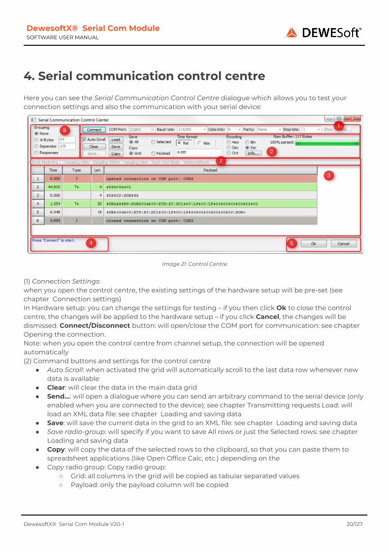
4. Serial communication control centre Here you can see the Serial Communication Control Centre dialogue which allows you to test your connection settings and also the communication with your serial device:
Image 21: Control Centre
(1) Connection Settings: when you open the control centre, the existing settings of the hardware setup will be pre-set (see chapter Connection settings) In Hardware setup: you can change the settings for testing – if you then click Ok to close the control centre, the changes will be applied to the hardware setup – if you click Cancel, the changes will be dismissed. Connect/Disconnect button: will open/close the COM port for communication: see chapter Opening the connection. Note: when you open the control centre from channel setup, the connection will be opened automatically (2) Command buttons and settings for the control centre
● Auto Scroll: when activated the grid will automatically scroll to the last data row whenever new data is available
● Clear: will clear the data in the main data grid ● Send…: will open a dialogue where you can send an arbitrary command to the serial device (only
enabled when you are connected to the device): see chapter Transmitting requests Load: will load an XML data file: see chapter Loading and saving data
● Save: will save the current data in the grid to an XML file: see chapter Loading and saving data ● Save radio-group: will specify if you want to save All rows or just the Selected rows: see chapter
Loading and saving data ● Copy: will copy the data of the selected rows to the clipboard, so that you can paste them to
spreadsheet applications (like Open Office Calc, etc.) depending on the ● Copy radio group: Copy radio group:
○ Grid: all columns in the grid will be copied as tabular separated values ○ Payload: only the payload column will be copied
DewesoftX® Serial Com Module V20-1 20/127

DewesoftX® Serial Com Module SOFTWARE USER MANUAL
● Time radio-group: will change the representation of the Time column: see chapter Time ● Time format: will change the representation of the Time column: see chapter Time Payload
Encoding radio-group: will change the representation of the Payload column: see chapter Payload Info: will show a list of all escape sequences (only active if the
● Payload Encoding is Esc): see chapter Payload, chapter Character escaping ● Raw Buffer and Progress bar: will show you how much data has been received and how much of
this data has already been parsed: see chapter Receiving Responses for details (3) the main data grid showing the communication data: see chapter Main Data Grid (4) Status label: will show you status/warning/error messages (5) Main dialogue buttons to close the control centre: see Connection Settings above (6) Grouping: will change the grouping of the Rx rows: see chapter Grouping (7) Send Requests bar: Only available when you have opened the control centre from channel setup and when you have defined some Requests (see 6 Requests on page 30): see also chapter Transmitting requests
4.1. Opening the connection After you have configured the the connection settings, you can click the Connect button to open the COM port for communication:
Image 22: Control Centre
Hint When the Control Centre is opened from the channel setup, the connection will automatically be established (you need not press the Connect button).
If the connection is okay (Image 22), you can see that ● the Connect button now changed to Disconnect (1) and that the Send functions are now active:
i.e. the Send Command button is now active and the request buttons on the Send Request bar ● there is a status line in the main data grid (2) ● the status label shows connection okay (3)
DewesoftX® Serial Com Module V20-1 21/127
DewesoftX® Serial Com Module SOFTWARE USER MANUAL
If any problem occurs, you will see an error-message and also the status label will turn red: The error number in the status label gives more detailed information:
● Error 2: means that the COM port does not exist (any longer). e.g. this can happen when you use a device that only emulates a COM port but is connected via USB to the computer. When you then disconnect the USB cable, also the emulated COM port may be gone.
● Error 5: usually indicates that the COM port is already opened by another application. Close all other applications that may use the COM port and try again.
Image 23: Connection failed
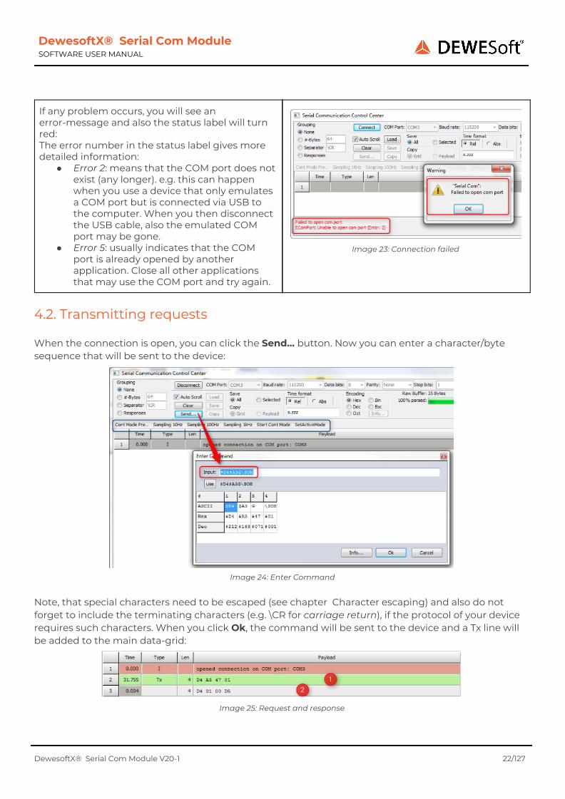
4.2. Transmitting requests When the connection is open, you can click the Send… button. Now you can enter a character/byte sequence that will be sent to the device:
Image 24: Enter Command
Note, that special characters need to be escaped (see chapter Character escaping) and also do not forget to include the terminating characters (e.g. \CR for carriage return), if the protocol of your device requires such characters. When you click Ok, the command will be sent to the device and a Tx line will be added to the main data-grid:
Image 25: Request and response
DewesoftX® Serial Com Module V20-1 22/127
DewesoftX® Serial Com Module SOFTWARE USER MANUAL
In the Image you can see the request that you have just sent to the device ((1) the green line of type Tx: transmit) and the response data from the device ((2) the grey lines of type Rx: receive). Note: when you click the Send… button the next time, the last input text will still be shown. Note: when you have opened the control centre from channel setup and you have defined some Requests (see chapter Requests), you will see all those requests in the Send requests bar (see blue rectangle in Image 24 above). When you click on any of those requests, they will be sent right away.
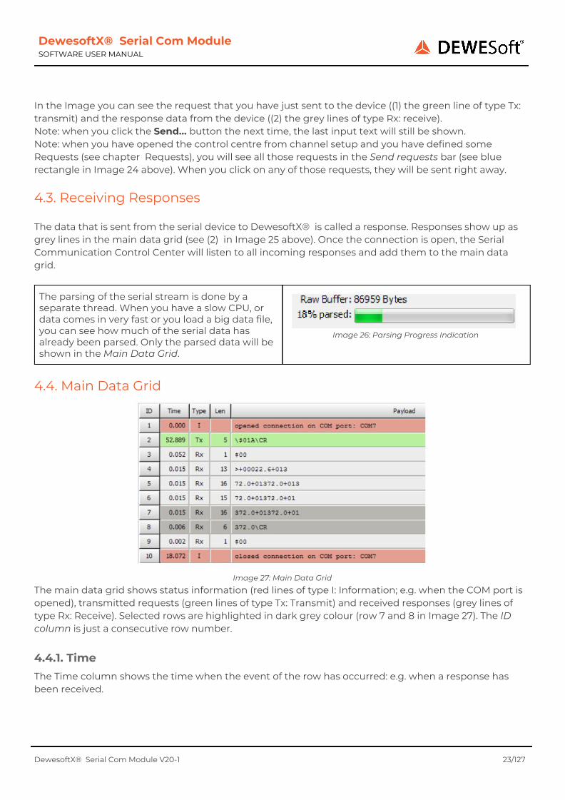
4.3. Receiving Responses The data that is sent from the serial device to DewesoftX® is called a response. Responses show up as grey lines in the main data grid (see (2) in Image 25 above). Once the connection is open, the Serial Communication Control Center will listen to all incoming responses and add them to the main data grid.
The parsing of the serial stream is done by a separate thread. When you have a slow CPU, or data comes in very fast or you load a big data file, you can see how much of the serial data has already been parsed. Only the parsed data will be shown in the Main Data Grid.
Image 26: Parsing Progress Indication
4.4. Main Data Grid
Image 27: Main Data Grid
The main data grid shows status information (red lines of type I: Information; e.g. when the COM port is opened), transmitted requests (green lines of type Tx: Transmit) and received responses (grey lines of type Rx: Receive). Selected rows are highlighted in dark grey colour (row 7 and 8 in Image 27). The ID column is just a consecutive row number.
4.4.1. Time The Time column shows the time when the event of the row has occurred: e.g. when a response has been received.
DewesoftX® Serial Com Module V20-1 23/127
DewesoftX® Serial Com Module SOFTWARE USER MANUAL
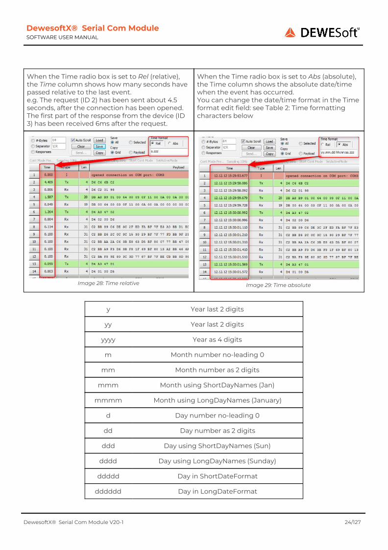
When the Time radio box is set to Rel (relative), the Time column shows how many seconds have passed relative to the last event. e.g. The request (ID 2) has been sent about 4.5 seconds, after the connection has been opened. The first part of the response from the device (ID 3) has been received 6ms after the request.
When the Time radio box is set to Abs (absolute), the Time column shows the absolute date/time when the event has occurred. You can change the date/time format in the Time format edit field: see Table 2: Time formatting characters below
Image 28: Time relative
Image 29: Time absolute
y Year last 2 digits
yy Year last 2 digits
yyyy Year as 4 digits
m Month number no-leading 0
mm Month number as 2 digits
mmm Month using ShortDayNames (Jan)
mmmm Month using LongDayNames (January)
d Day number no-leading 0
dd Day number as 2 digits
ddd Day using ShortDayNames (Sun)
dddd Day using LongDayNames (Sunday)
ddddd Day in ShortDateFormat
dddddd Day in LongDateFormat
DewesoftX® Serial Com Module V20-1 24/127

DewesoftX® Serial Com Module SOFTWARE USER MANUAL
am/pm Use after h : gives 12 hours + am/pm
a/p Use after h : gives 12 hours + a/p
ampm As a/p but TimeAMString,TimePMString
/ Substituted by DateSeparator value
: Substituted by TimeSeparator value
c Use ShortDateFormat + LongTimeFormat
h Hour number no-leading 0
hh Hour number as 2 digits
n Minute number no-leading 0
nn Minute number as 2 digits
s Second number no-leading 0
ss Second number as 2 digits
z Milli-sec number no-leading 0s
zzz Milli-sec number as 3 digits
t Use ShortTimeFormat
tt Use LongTimeFormat
4.4.2. Type The Type column can have following values:
Name Colour Value Description
Information red I Information text
Transmitted data green Tx Data that has been sent from DewesoftX® to the serial device
Received data grey Rx1 Data that has received by from DewesoftX® from the serial device
skipped Only for grouping type Responses: when the data did not match any of the defined Responses: see
chapter Grouping Type: Responses for more details
... Only for grouping types other than None: when the data has not matched any of the grouping criteria, it will be shown in the last line (for an example see
Image 42: Grouping: 8 Bytes (Esc) on page 21)
DewesoftX® Serial Com Module V20-1 25/127

DewesoftX® Serial Com Module SOFTWARE USER MANUAL
4.4.3. Len The length of the transmitted or received data in bytes.
4.4.4. Payload The Payload column shows the data for the given column. For information columns it's just plain text. For requests and responses, it is the data that has been sent to or received from the serial device.
You can use the Payload Encoding radio box to select how to display the data of the Rx/Tx rows.
Image 30: Payload Encoding
4.4.4.1. Hex The bytes are encoded in hexadecimal notation and they are separated by a space from each other. e.g. the first encoded byte in row 2 is 24 which is 36 in decimal notation and represents the character $.
Image 31: Encoding Hex
4.4.4.2. Dec The bytes are encoded in decimal notation and they are separated by a space from each other. e.g. the first encoded byte in row 2 is 036 which represents the character $.
Image 32: Encoding Dec
DewesoftX® Serial Com Module V20-1 26/127
DewesoftX® Serial Com Module SOFTWARE USER MANUAL
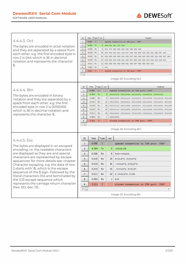
4.4.4.3. Oct The bytes are encoded in octal notation and they are separated by a space from each other. e.g. the first encoded byte in row 2 is 044 which is 36 in decimal notation and represents the character $.
Image 33: Encoding Oct
4.4.4.4. Bin The bytes are encoded in binary notation and they are separated by a space from each other. e.g. the first encoded byte in row 2 is 00100100 which is 36 in decimal notation and represents the character $.
Image 34: Encoding Bin
4.4.4.5. Esc The bytes are displayed in an escaped encoding; i.e. the readable characters are displayed as they are and special characters are represented by escape sequences: for more details see: chapter Character escaping. e.g. the data of row 2 starts with \$, which is the escape sequence of the $ sign. Followed by the literal characters 01A and terminated by the \CR escape sequence which represents the carriage return character (hex: 0D, dec: 13).
Image 35: Encoding Bin
DewesoftX® Serial Com Module V20-1 27/127
DewesoftX® Serial Com Module SOFTWARE USER MANUAL
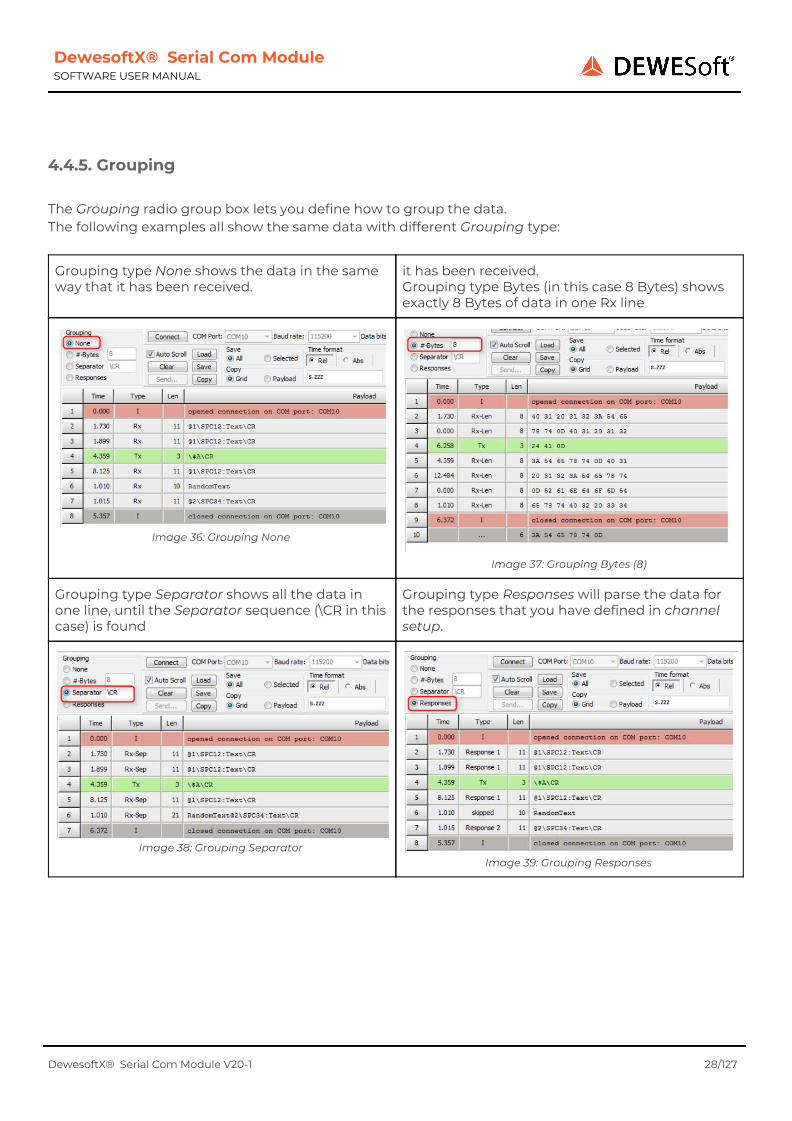
4.4.5. Grouping The Grouping radio group box lets you define how to group the data. The following examples all show the same data with different Grouping type:
Grouping type None shows the data in the same way that it has been received.
it has been received. Grouping type Bytes (in this case 8 Bytes) shows exactly 8 Bytes of data in one Rx line
Image 36: Grouping None
Image 37: Grouping Bytes (8)
Grouping type Separator shows all the data in one line, until the Separator sequence (\CR in this case) is found
Grouping type Responses will parse the data for the responses that you have defined in channel setup.
Image 38: Grouping Separator
Image 39: Grouping Responses
DewesoftX® Serial Com Module V20-1 28/127
DewesoftX® Serial Com Module SOFTWARE USER MANUAL
4.4.5.1. Grouping Type: None
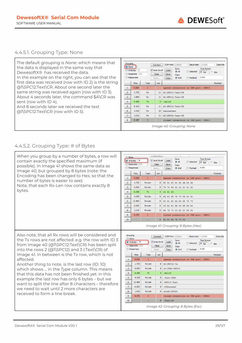
The default grouping is None: which means that the data is displayed in the same way that DewesoftX® has received the data. In the example on the right, you can see that the first data was received (row with ID 2) is the string @1\SPC12:Text\CR. About one second later the same string was received again (row with ID 3). About 4 seconds later, the command $A\CR was sent (row with ID 4). And 8 seconds later we received the text @1\SPC12:Text\CR (row with ID 5).
Image 40: Grouping: None
4.4.5.2. Grouping Type: # of Bytes
When you group by a number of bytes, a row will contain exactly the specified maximum (if possible). In Image 41 shows the same data as Image 40, but grouped by 8 bytes (note: the Encoding has been changed to Hex, so that the number of bytes is easier to see): Note, that each Rx-Len row contains exactly 8 bytes.
Image 41: Grouping: 8 Bytes (Hex)
Also note, that all Rx rows will be considered and the Tx rows are not affected: e.g. the row with ID 3 from Image 40 (@1\SPC12:Text\CR) has been split into the rows 2 (@1\SPC12) and 3 (:Text\CR) of Image 41. In between is the Tx row, which is not affected. Another thing to note, is the last row (ID: 10) which shows … in the Type column. This means that this data has not been finished yet: in this example the last row has only 6 bytes – but we want to split the line after 8 characters – therefore we need to wait until 2 more characters are received to form a line break.
Image 42: Grouping: 8 Bytes (Esc)
DewesoftX® Serial Com Module V20-1 29/127

DewesoftX® Serial Com Module SOFTWARE USER MANUAL
Hint When you change the #-Bytes in the edit field, the grouping will be applied when you press the Enter key or when you leave the edit field (set the focus to another control).
4.4.5.3. Grouping Type: Separator
When you group by Separator a new receive line will be made whenever the Separator string is found in the received data. Image 43 shows the same data as Image 41 and Image 40, but this time grouped by the carriage return byte \CR. You can see that, whenever the carriage return byte \CR occurs in the data, a new Rx-Sep line is shown: i.e. the last character of each Rx-Sep line is a \CR. You can also specify several characters as Separator: e.g. \CR\LF. If you specify a separator that does not exist in the received data, you will end up with one very long line.
Image 43: Grouping: Separator
Hint When you change the Separator in the edit field, the grouping will be applied when you press the Enter key or when you leave the edit field (set the focus to another control).
4.4.5.4. Grouping Type: Responses
Hint The grouping type Responses are only enabled, when you have opened the control centre from channel setup and when you have defined some Responses (see chapter Responses). Note: this is because the result of this grouping is dependent on the current Response definitions in
the loaded setup.
Image 44 shows the same data as Image 43 (and Image 41 and Image 40), but this time grouped by the Responses (see chapter Responses) that have been defined in the channel setup. The Type column will show you the name of the matching response (or skipped if the data did not match any response). In this example we have defined 2 Responses: Response 1 starts with @1\SPC until \CR. Response 2 starts with @ until \CR. In the data grid you can see that we have received Response 1 three times (lines 2, 3, 5). The text RandomText does not match any Response – therefore the Type column says skipped. Line 7 did not match our first response (it does not start with @1\SPC, but only with @), but it matches the second response.
Image 44: Grouping: Responses
DewesoftX® Serial Com Module V20-1 30/127

DewesoftX® Serial Com Module SOFTWARE USER MANUAL
4.5. Loading and saving data
You can use the Save button to store the data in the main data grid to an XML file. The setting of the Save radio group is important. If All is active, all rows in the main data grid will be stored in the XML file. If Selected is active, only the selected rows of the main data grid will be saved to the XML file (in Image 45 below, the rows 3 and 4 are selected). Only the raw data will be stored in the file: i.e. exactly what you see when you switch to Grouping mode None (see chapter Grouping Type: None). NOTE: Since only the raw data is saved, the result of Grouping type Responses (see chapter Grouping Type: Responses above) depends on the currently loaded setup.
Image 45: Load/Save Data
You can then use the Load button to open the saved files again.
Hint The display settings (like Time, Time format, Payload Encoding) do not matter when you save a file; i.e. after reloading you can still change all those settings.
DewesoftX® Serial Com Module V20-1 31/127

DewesoftX® Serial Com Module SOFTWARE USER MANUAL
5. Hardware setup When you have successfully installed the Plug-in (see chapter Plug-in Installation), it will show up in the Hardware setup:
To open the Hardware Setup click on Options– Settings Note: Hardware Setup will be disabled during the measurement.
Image 46: Open Hw Setup
In the Hardware Setup select Extensions and then select in the Extensions tree (if you don't find it, see: chapter Plug-in Installation). (1) Toolbar (2) Shows a list of all configured devices (3) General log level: see chapter Log files Note that also each device has its own log level
Image 47: Hardware Setup
5.1. Devices The Module supports several serial devices. Use the toolbar buttons to manipulate the device list:
● Control Centre : allows you to test the selected serial device: see chapter Serial communication control centre Note: you can also double click a row in the device list to open the control centre
● Add : Add a new device (will only be enabled if there is still a free COM port) see chapter Add/Edit Device below Edit :
● Edit the selected device (will only be enabled if you have selected exactly one device in the list) see chapter Add/Edit Device below
● Remove : Will remove the selected device from the list. Note: you cannot remove the last device. ● Up/Down: Will change the position of the device in the list. This order will also be used in the
channel setup. The top device will be the leftmost device in channel setup.
DewesoftX® Serial Com Module V20-1 32/127
DewesoftX® Serial Com Module SOFTWARE USER MANUAL
5.1.1. No Com Ports
When there are no COM ports on your PC, you will see an error-message. You can press the Scan for COM ports buttons to rescan for COM ports: i.e. when you connect an RS232-to-USB converter to your PC it will mount a virtual COM port.
Image 48: No Com Ports
5.1.2. Add/Edit Device
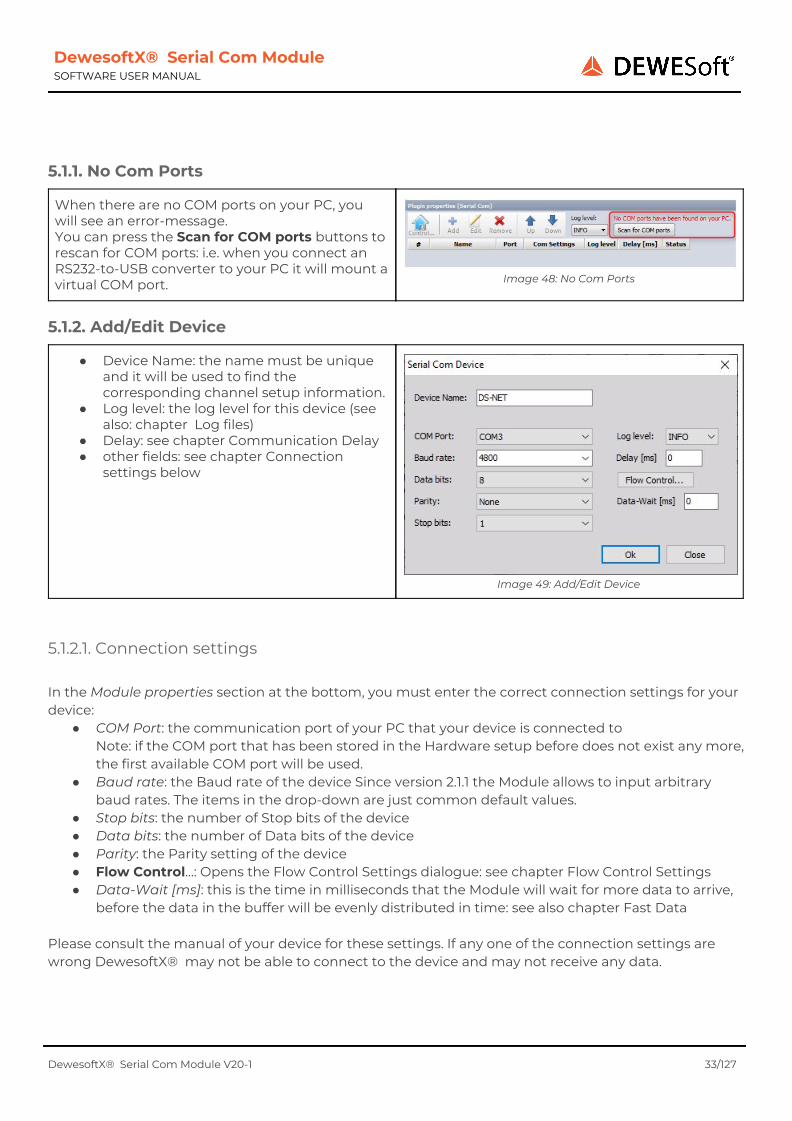
● Device Name: the name must be unique and it will be used to find the corresponding channel setup information.
● Log level: the log level for this device (see also: chapter Log files)
● Delay: see chapter Communication Delay ● other fields: see chapter Connection
settings below
Image 49: Add/Edit Device
5.1.2.1. Connection settings In the Module properties section at the bottom, you must enter the correct connection settings for your device:
● COM Port: the communication port of your PC that your device is connected to Note: if the COM port that has been stored in the Hardware setup before does not exist any more, the first available COM port will be used.
● Baud rate: the Baud rate of the device Since version 2.1.1 the Module allows to input arbitrary baud rates. The items in the drop-down are just common default values.
● Stop bits: the number of Stop bits of the device ● Data bits: the number of Data bits of the device ● Parity: the Parity setting of the device ● Flow Control…: Opens the Flow Control Settings dialogue: see chapter Flow Control Settings ● Data-Wait [ms]: this is the time in milliseconds that the Module will wait for more data to arrive,
before the data in the buffer will be evenly distributed in time: see also chapter Fast Data Please consult the manual of your device for these settings. If any one of the connection settings are wrong DewesoftX® may not be able to connect to the device and may not receive any data.
DewesoftX® Serial Com Module V20-1 33/127

DewesoftX® Serial Com Module SOFTWARE USER MANUAL
When you select a COM Port that is already in use or cannot be opened for any other reason, you will get a warning message when you try to start the measurement or go to the setup screen:
5.2. Log files The Module will write log files during operation. The amount of log messages is configurable via the Log level drop down box in the Hardware setup. The name of the logfile for the Module is SerialComModuleLogfile.log. Moreover each device will write a log file with the name: Serial_Com_[COM-PORT].log, where COM-PORT is the currently used COM port (as defined in the hardware setup: e.g. Serial_Com_COM3.log. When the Module is started, it will immediately start to log to the windows temporary directory. As soon as the DewesoftX® application is available to the Module, all subsequent logs will be written to the standard DewesoftX® log directory (e.g. D:\DewesoftX\System\V7_0\Logs).
5.2.1 Log levels
With the log level drop down box you can set the detail level of the logging function. If you set a high log level (e.g. TRACE, ALL) a lot of log messages will be written and the log files will roll over quite often. This is also dependent on the sample rate – the higher the sample rate is, the more often data will be fetched and therefore more log messages will be written.
For production-use the log level INFO is recommended.
Log level Description
Error Will only log error messages
Warn Will also log warning messages
Info Will also log info messages – this is recommended for production use
Debug Will also log debug messages
Trace will also log trace messages: e.g. data that is received via the RS232 port.
All will log all messages everything
DewesoftX® Serial Com Module V20-1 34/127

DewesoftX® Serial Com Module SOFTWARE USER MANUAL
5.3. Communication Delay There is of course a certain delay, between the real time when the measurement data is taken and when it is received in DewesoftX® : e.g. because the serial device is doing some filtering, some calculations and also the serial transmission takes some finite amount of time (dependant on the baud rate and the amount of data that will be sent). With the delay time setting you can compensate for those delays. The delay time will simply be subtracted from the time of the signal; i.e. the signal will be shifted to the left on the time-axis. In the example below you can see the original signal in green and the red signal has a delay of 5ms.
Image 50: Delay 5ms
Note: the delay time only affects the responses (the data that we receive from the device).
DewesoftX® Serial Com Module V20-1 35/127

DewesoftX® Serial Com Module SOFTWARE USER MANUAL
6. Channel Setup
When you go to the Channel setup of the Module you will see a screen similar to Image 51. (1) Shows the version number of the SerialCom Module (2) The status label is only active, if there are warning or error messages: see chapter Warnings and Errors (3) List of all defined devices: see chapter Device List (4) Device toolbar: see chapter Device Toolbar (5) This section shows the connection settings of the current device that you have made in the Hardware setup (see chapter Hardware setup) (6) Here you can switch between the main tab-sheets of the channel setup. The specific tab-sheets will be described in detail in the corresponding chapters: Request, Responses, Monitoring, Default Settings, The content of this area is depending on the selected tab-sheet: 6 Requests , Responses, 7 Monitoring, Default Settings
Image 51: Channel Setup
6.1. Device List
The device list will show the name of all devices (and the assigned COM port) that are defined in the hardware setup (in the same order as they are defined in the hardware setup). If orphaned devices (see chapter Orphaned devices below) exist, they will be shown at the end of the list (right side). Devices which contain errors or warnings will be displayed in red/orange colour (see chapter Warnings and Errors). In the example above the 2nd device named Microstrain has warnings.
6.1.1. Orphaned devices An orphaned device is a device that exists in channel setup, but does not exist any more in the current hardware setup. Orphaned devices may occur in the following cases:
1. if you go to hardware setup, delete one of the devices (or rename a device) and go back to channel setup
2. if you load a setup which included a device that does not exist in the current hardware setup
DewesoftX® Serial Com Module V20-1 36/127
DewesoftX® Serial Com Module SOFTWARE USER MANUAL
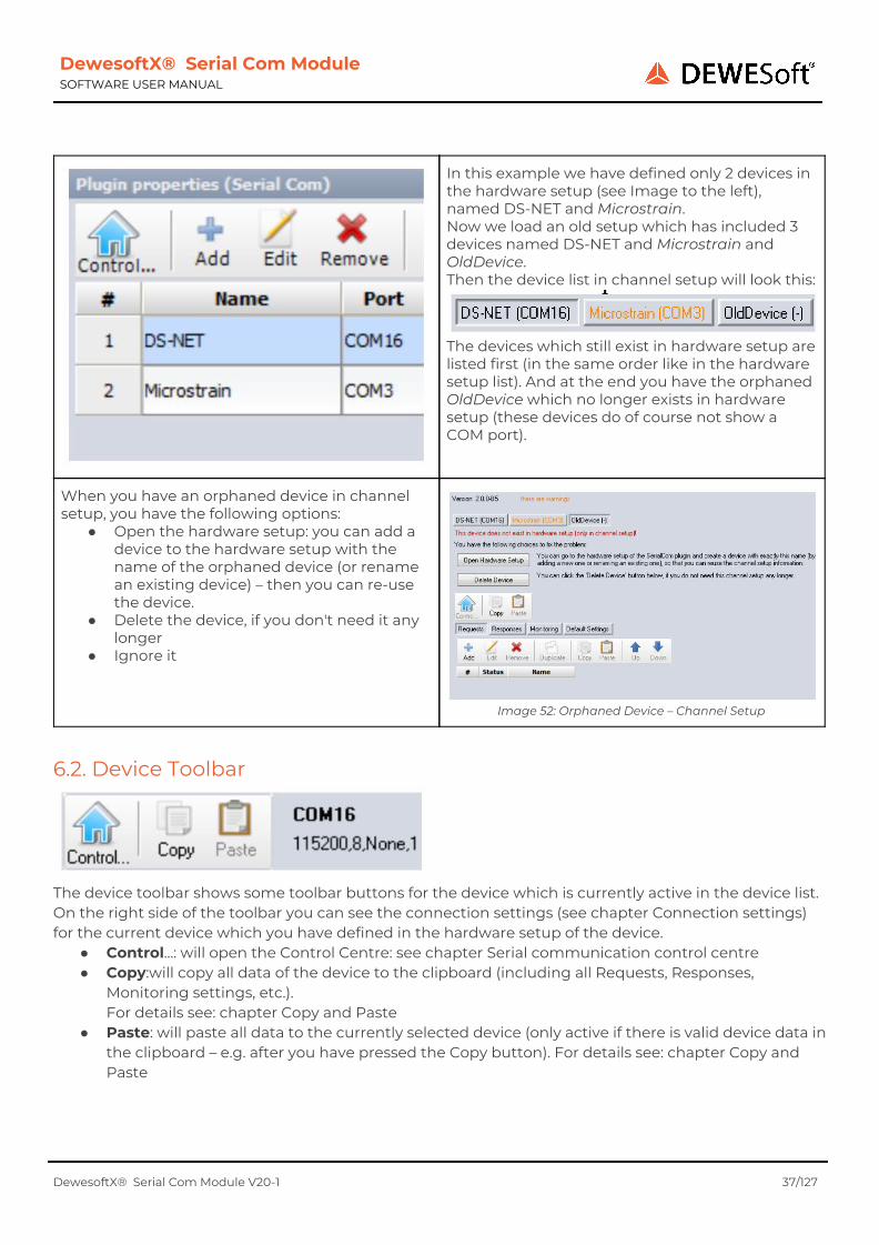
In this example we have defined only 2 devices in the hardware setup (see Image to the left), named DS-NET and Microstrain. Now we load an old setup which has included 3 devices named DS-NET and Microstrain and OldDevice. Then the device list in channel setup will look this:
The devices which still exist in hardware setup are listed first (in the same order like in the hardware setup list). And at the end you have the orphaned OldDevice which no longer exists in hardware setup (these devices do of course not show a COM port).
When you have an orphaned device in channel setup, you have the following options:
● Open the hardware setup: you can add a device to the hardware setup with the name of the orphaned device (or rename an existing device) – then you can re-use the device.
● Delete the device, if you don't need it any longer
● Ignore it
Image 52: Orphaned Device – Channel Setup
6.2. Device Toolbar
The device toolbar shows some toolbar buttons for the device which is currently active in the device list. On the right side of the toolbar you can see the connection settings (see chapter Connection settings) for the current device which you have defined in the hardware setup of the device.
● Control...: will open the Control Centre: see chapter Serial communication control centre ● Copy:will copy all data of the device to the clipboard (including all Requests, Responses,
Monitoring settings, etc.). For details see: chapter Copy and Paste
● Paste: will paste all data to the currently selected device (only active if there is valid device data in the clipboard – e.g. after you have pressed the Copy button). For details see: chapter Copy and Paste
DewesoftX® Serial Com Module V20-1 37/127

DewesoftX® Serial Com Module SOFTWARE USER MANUAL
6.3. Warnings and Errors The Module may show some warning and error messages:
Image 53: Errors and Warnings
Warnings will be highlighted in orange, errors in red. There is a label in the main channel setup form that shows you if there are any warnings or errors. If so, the items with warnings/errors are also highlighted in the corresponding colour (In the example above, you can see that the caption of the Requests tab-sheet is red, because there, request 3 has an error. Besides this error you can also see that there is at least one warning in the Responses tab-sheet (because it is orange). When you move the mouse over an element with a warning or error, you will see a hint with the details of the warning/error. In the screen-shot below, you can see that the warning of the response name is, that the same name is already used by another response.
Image 54: Warning Hint
DewesoftX® Serial Com Module V20-1 38/127
DewesoftX® Serial Com Module SOFTWARE USER MANUAL
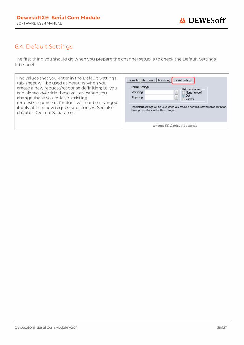
6.4. Default Settings The first thing you should do when you prepare the channel setup is to check the Default Settings tab-sheet.
The values that you enter in the Default Settings tab-sheet will be used as defaults when you create a new request/response definition; i.e. you can always override these values. When you change these values later, existing request/response definitions will not be changed; it only affects new requests/responses. See also chapter Decimal Separators
Image 55: Default Settings
DewesoftX® Serial Com Module V20-1 39/127

DewesoftX® Serial Com Module SOFTWARE USER MANUAL
7. Requests A request (aka. Command) is a byte sequence that will be sent from DewesoftX® to the serial device. Some devices may not have any commands (e.g. a weather station may just start to send data when it's powered on and stop when it's powered off) – in this case you do not need to define any request, you can skip this chapter and continue with your response definitions: 7 Responses on page 47. Each request consists of one or more request parts: the request parts actually define what data you sent to the device.
7.1. Requests tab-sheet
In the Requests tab-sheet there is a list of all defined requests. (1) on the top you can see the main toolbar (2) the main data grid shows a list of all requests: selected requests are highlighted in light blue (e.g. in the image to the right, the requests 2 and 3 are selected)
7.1.1. Requests: Main Toolbar The main toolbar for requests has following buttons:
Add will add a new request and open a dialogue window so that you can configure it see also chapter Add/Edit Request
Edit will open a dialogue window so that you can edit the currently selected request (only active if exactly one request is selected)
see also chapter Add/Edit Request
Remove will remove all selected requests
Duplicate will duplicate the selected request (only active if exactly one request is selected) see also chapter Copy and Paste
Copy will copy the currently selected request/s to the clipboard see also chapter Copy and Paste
Paste will paste the request/s (that has/have been copied before) back into DewesoftX® see also chapter Copy and Paste
DewesoftX® Serial Com Module V20-1 40/127
DewesoftX® Serial Com Module SOFTWARE USER MANUAL
Up Will move the selected request/s up: see chapter Requests Order below
Down Will move the selected request/s down: see chapter Requests Order below
7.1.2.Requests Order The order of the requests in the requests list is only relevant if several requests have the same activation event (see chapter Activation Event). To change the order you can use the Up/Down buttons in the toolbar or you can drag and drop the row in the data grid (see chapter Drag And Drop).
Example When we have 2 requests and both have the activation event 'On Start' then the first request in the requests list will be executed first and then the second one in the list.
7.2. Add/Edit Request To create a new request, click the Add button in the Requests tab-sheet. To edit an existing request, select it in the main data grid and then click Edit or just double click the row of the datagrid.
Image 56: Create/Edit request
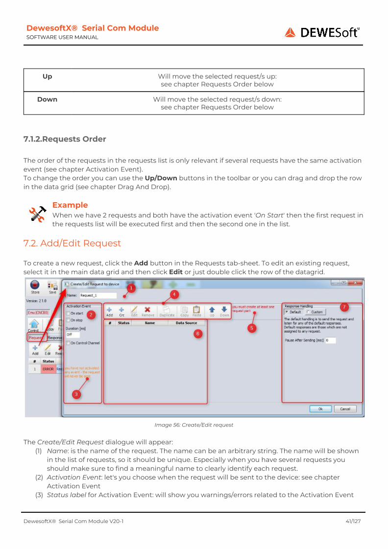
The Create/Edit Request dialogue will appear:
(1) Name: is the name of the request. The name can be an arbitrary string. The name will be shown in the list of requests, so it should be unique. Especially when you have several requests you should make sure to find a meaningful name to clearly identify each request.
(2) Activation Event: let's you choose when the request will be sent to the device: see chapter Activation Event
(3) Status label for Activation Event: will show you warnings/errors related to the Activation Event
DewesoftX® Serial Com Module V20-1 41/127
DewesoftX® Serial Com Module SOFTWARE USER MANUAL
(4) Main toolbar: provides functions to manipulate the parts of the request: see chapter Request
Parts (5) Status label for the parts of the request (6) Main data grid: List of the parts of this request: see chapter Request Parts (7) Response Handling: let's you define how to handle responses for this request: see chapter
Request: Response Handling
7.2.1. Activation Event Let's you choose when the request will be sent to the device:
● On Start: will be sent immediately after the COM port has been opened (e.g. when you start the measurement). So you can use it to initialize your device: e.g. you may send a command to tell the device to start sending data to DewesoftX® .
● On Stop: will be sent before the COM port is closed (e.g. when you stop the measurement). You can use it to finalize your device: e.g. you may send a command to tell the device to stop sending data to DewesoftX® . Note: In this case the Response Handling will be ignored (i.e. when you stop the Measurement in DewesoftX® the Module does not wait for any responses of the serial device)
● Duration [ms]: if this is activated the request will be sent every x milliseconds to the device. Note: this is implemented using Windows timers: so the timer will not always fire exactly after the specified duration, but it will for sure not fire before the specified duration.
● On Control Channel: if this is activated, the Module will create a DewesoftX® control channel. You can then assign a visual control (e.g. a push-button) to this channel and whenever the button is pressed, the request will be sent to the device. Or you can activate the control channel via the DewesoftX® alarm handling. See 6.2.1.1 Control Channel on page 32 for details
Note: you should activate at least one of the options above, otherwise the request will never be sent.
7.2.1.1. User input If this is activated, the Module will create a DewesoftX® user input. You can then assign a visual control (e.g. a push-button) to this channel and whenever the button is pressed, the request will be sent to the device. In this example, we create a request called SerialRequest1, with a single request part that has a fixed byte sequence: \$ALARM\CR. We activate only one Activation Event: the On User input.
DewesoftX® Serial Com Module V20-1 42/127

DewesoftX® Serial Com Module SOFTWARE USER MANUAL
Image 57: Activation Event: On User input
In the screen design mode of DewesoftX® we can now drag an Input control display to our measurement screen. You can see in the channel list, that only control channels can be assigned to this visual control – in our example we have exactly one control channel, which has the same name as the request, that we have defined: SerialRequest1.
After assigning the control channel SerialRequest1 to the Input control display, we can change the Display Type of the Input control display to Push button.
Image 58: Input control display
Image 59: Push button
DewesoftX® Serial Com Module V20-1 43/127
DewesoftX® Serial Com Module SOFTWARE USER MANUAL
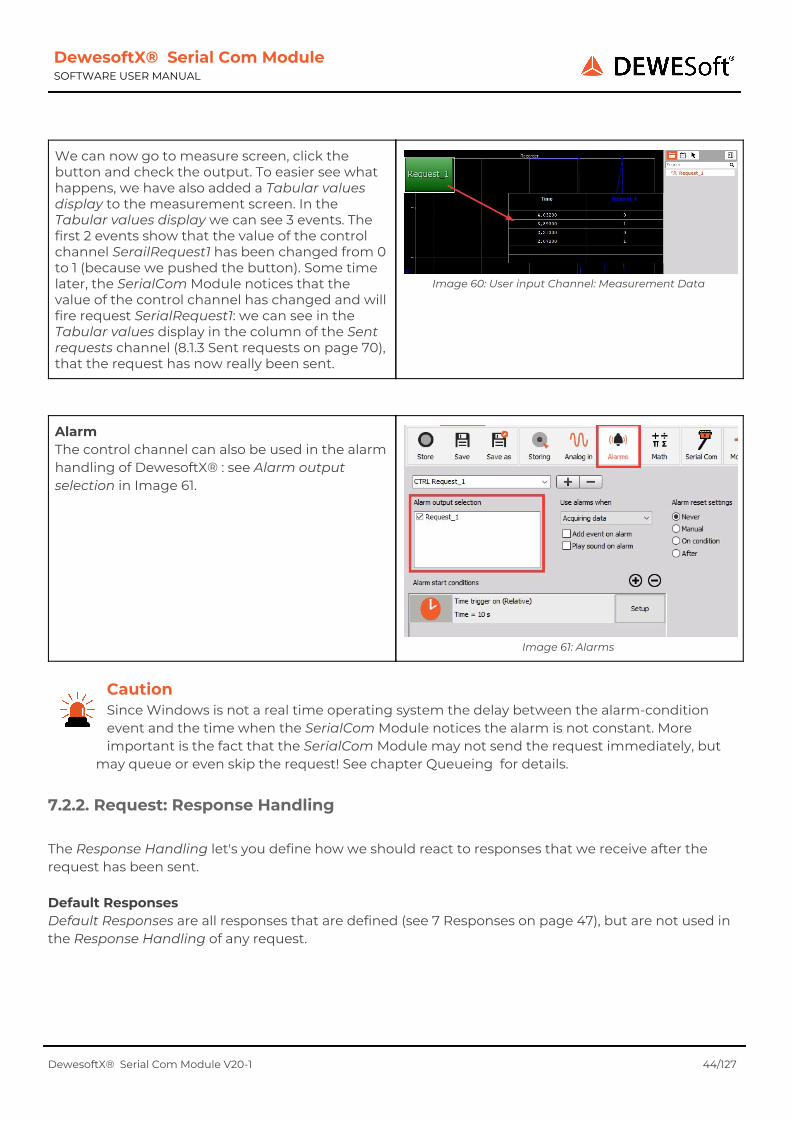
We can now go to measure screen, click the button and check the output. To easier see what happens, we have also added a Tabular values display to the measurement screen. In the Tabular values display we can see 3 events. The first 2 events show that the value of the control channel SerailRequest1 has been changed from 0 to 1 (because we pushed the button). Some time later, the SerialCom Module notices that the value of the control channel has changed and will fire request SerialRequest1: we can see in the Tabular values display in the column of the Sent requests channel (8.1.3 Sent requests on page 70), that the request has now really been sent.
Image 60: User input Channel: Measurement Data
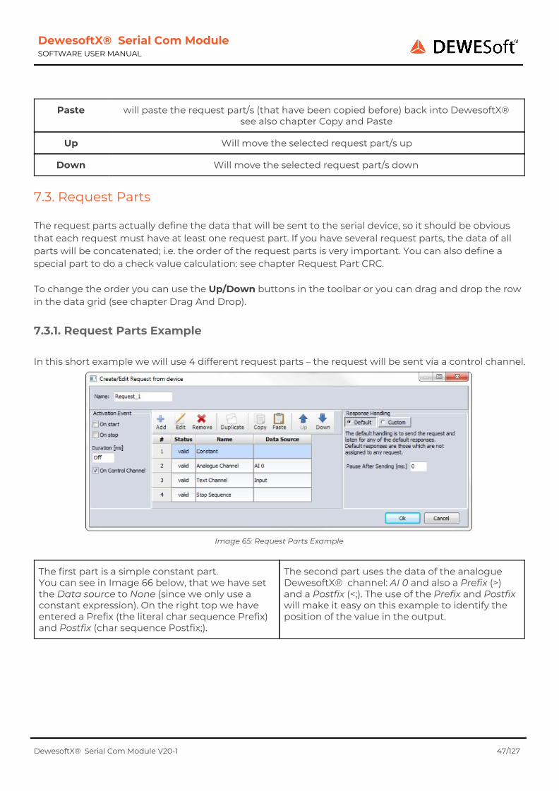
Alarm The control channel can also be used in the alarm handling of DewesoftX® : see Alarm output selection in Image 61.
Image 61: Alarms
Caution Since Windows is not a real time operating system the delay between the alarm-condition event and the time when the SerialCom Module notices the alarm is not constant. More important is the fact that the SerialCom Module may not send the request immediately, but
may queue or even skip the request! See chapter Queueing for details.
7.2.2. Request: Response Handling The Response Handling let's you define how we should react to responses that we receive after the request has been sent. Default Responses Default Responses are all responses that are defined (see 7 Responses on page 47), but are not used in the Response Handling of any request.
DewesoftX® Serial Com Module V20-1 44/127

DewesoftX® Serial Com Module SOFTWARE USER MANUAL
7.2.2.1. Default The default setting (Pause After Sending value = 0) is to send the request and listen to all default responses. The next request may be sent immediately after the current request.
Image 62: Default
7.2.2.2. Pause After Sending If the Pause After Sending value is > 0 then the Module will send the request to the serial device and make sure that, during the specified time, no other request will be sent. In the pause interval, it still listens to all default responses. Even if we receive a valid response during the pause interval, no other request will be sent (in contrast to Custom below)
Image 63: Pause
7.2.2.3. Custom
The Custom handling allows you to select individual responses. After sending the request the Module will only listen to the selected responses (other responses will be ignored). The next request will not be sent until we have received any of the selected responses (in contrast to Pause After Sending above) or until the Timeout period has been reached. Example: (related to Image 64): If we receive 'Response EPAD 01' or 'Error Response' after sending the request (in less than 250 ms), the next request can be sent (if any). If we receive 'Response EPAD02' in the Timeout period, it will be ignored: the Module keeps waiting. If we do not receive any response in the Timeout period, the next request may be sent (if any) and we will continue to listen for the default responses Hints:
● To select a consecutive group of responses, click the first response, hold down the SHIFT key, and then click the last response.
● To select non-consecutive responses, hold down CTRL, and then click each response you want to select.
Image 64: Custom
DewesoftX® Serial Com Module V20-1 45/127

DewesoftX® Serial Com Module SOFTWARE USER MANUAL
7.2.2.4. Queueing When a request should be executed (e.g. because you click a button, or it's timer fire), it will first be added to a queue and will then eventually be executed – depending on other requests in the queue and on the Response Handling settings of those requests. If the same request is already in the queue (or currently active; i.e. it has been sent and we still wait for a reply), then it will not be added to the queue again. In this case a text-info will be added to the status channel (if the status channel is activated - see chapter Status Channel). Always the oldest request in the queue will be executed next.
Example Let's assume we have Request A with Activation Event On start and Pause After Sending set to 1000ms and Request B with an Activation Event Duration of 100ms.
When we start the measurement, Request A will be sent immediately. After about 100ms the timer for Request B will fire and Request B will be added to the queue (It will not be executed, because Request A's Pause After Sending interval of 1000ms is not over yet). The request will already be built when it is inserted into the queue; i.e. if a request part uses some channel data (see chapter Channel data), then the current value of the channel at the time when the request is fired is used. After another 100ms the timer for Request B will fire again. This time Request B will not even be added to the queue, because the first Request B is still in the queue. The same will now happen every 100ms, until Request A's Pause After Sending interval of 1000ms is over. Right after Request A's Pause After Sending interval of 1000ms is over, Request B (which is still in the queue) will be sent.
7.2.3. Request: Main Toolbar
Add will add a new request part and open a dialogue window so that you can configure it see also chapter Request Parts
Cre will add a CRC part for this request and open a dialogue window so that you can configure it
see also: chapter Request Part Crc
Edit will open a dialogue window so that you can edit the currently selected request part or CRC (only active if exactly one request part is selected)
see also chapter Request Parts
Remove will remove all selected request parts
Duplicate will duplicate the selected request part (only active if exactly one request part is selected)
see also chapter Copy and Paste
Copy will copy the currently selected request part to the clipboard see also chapter Copy and Paste
DewesoftX® Serial Com Module V20-1 46/127
DewesoftX® Serial Com Module SOFTWARE USER MANUAL
Paste will paste the request part/s (that have been copied before) back into DewesoftX® see also chapter Copy and Paste
Up Will move the selected request part/s up
Down Will move the selected request part/s down
7.3. Request Parts The request parts actually define the data that will be sent to the serial device, so it should be obvious that each request must have at least one request part. If you have several request parts, the data of all parts will be concatenated; i.e. the order of the request parts is very important. You can also define a special part to do a check value calculation: see chapter Request Part CRC. To change the order you can use the Up/Down buttons in the toolbar or you can drag and drop the row in the data grid (see chapter Drag And Drop).
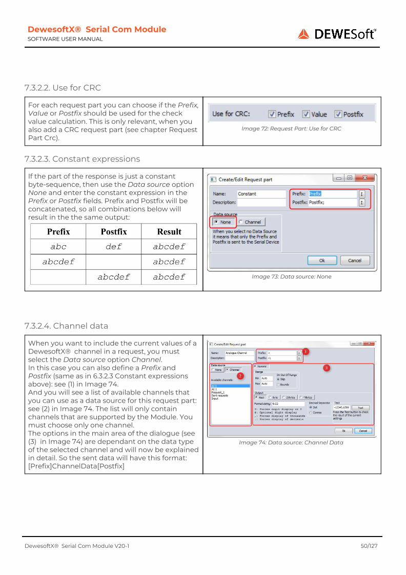
7.3.1. Request Parts Example In this short example we will use 4 different request parts – the request will be sent via a control channel.
Image 65: Request Parts Example
The first part is a simple constant part. You can see in Image 66 below, that we have set the Data source to None (since we only use a constant expression). On the right top we have entered a Prefix (the literal char sequence Prefix) and Postfix (char sequence Postfix;).
The second part uses the data of the analogue DewesoftX® channel: AI 0 and also a Prefix (>) and a Postfix (<;). The use of the Prefix and Postfix will make it easy on this example to identify the position of the value in the output.
DewesoftX® Serial Com Module V20-1 47/127

DewesoftX® Serial Com Module SOFTWARE USER MANUAL
Image 66: Request Part: Constant
Image 67: Request Part: Analogue
The 3rd request part shows how to output a text-channel. We use “ as Prefix and Postfix.
The last part is a fixed string again. Many serial protocols need a special string at the end of every request. In this case we use only one character: the carriage return character \CR. Note: we could also enter the character in the Prefix instead of the Postfix – but since the Prefix is empty in this case, it has the same effect. Note: we could also decide to skip this part completely and just add the carriage return character to the end of the Postfix in the 3rd request.
Image 68: Request Part: Text
Image 69: Request Part: Stop sequence
DewesoftX® Serial Com Module V20-1 48/127

DewesoftX® Serial Com Module SOFTWARE USER MANUAL
When we start the measurement and fire the request, we can see the data that will be sent to the serial port in the Sent requests channel: see Image 70. Note that special characters (like the trailing \CR) will not be visible in the DewesoftX® Tabular values display.
Image 70: Sent requests
In the table below you can see how the data relates to the request parts – we use the top entry of Image 70: Sent requests for this example:
Data: Prefix Postfix; > -1.55 <; “ Text Channel
“ \CR
Notes: Prefix Postfix Prefix Data Postfix Prefix Data Postfix Postfix
Request Part:
Part 1 Part 2 Part 3 Part 4
7.3.2. Request Part
7.3.2.1. BinHex Encoding
For each request part you can choose if the Prefix, Value or Postfix should be BinHex encoded or not. The Value will be encoded right before it is sent. So all other conversions, formatting, etc. will be done before the encoding.
Image 71: Request Part: BinHex Encoding
When using BinHex encoding, the hexadecimal representation of byte is converted to 2 hexadecimal bytes, each representing the ASCII code of the hexadecimal character.
Example The single byte value of #42 has the hexadecimal representation $2A. Now every character of the hexadecimal representation is converted to it's ASCII code.
2 → #50, $32 A → #65, $41 So the BinHex encoded value consists of the 2 bytes $32 $41.
DewesoftX® Serial Com Module V20-1 49/127
DewesoftX® Serial Com Module SOFTWARE USER MANUAL
7.3.2.2. Use for CRC
For each request part you can choose if the Prefix, Value or Postfix should be used for the check value calculation. This is only relevant, when you also add a CRC request part (see chapter Request Part Crc).
Image 72: Request Part: Use for CRC
7.3.2.3. Constant expressions
If the part of the response is just a constant byte-sequence, then use the Data source option None and enter the constant expression in the Prefix or Postfix fields. Prefix and Postfix will be concatenated, so all combinations below will result in the the same output:
Image 73: Data source: None
7.3.2.4. Channel data
When you want to include the current values of a DewesoftX® channel in a request, you must select the Data source option Channel. In this case you can also define a Prefix and Postfix (same as in 6.3.2.3 Constant expressions above): see (1) in Image 74. And you will see a list of available channels that you can use as a data source for this request part: see (2) in Image 74. The list will only contain channels that are supported by the Module. You must choose only one channel. The options in the main area of the dialogue (see (3) in Image 74) are dependant on the data type of the selected channel and will now be explained in detail. So the sent data will have this format: [Prefix]ChannelData[Postfix]
Image 74: Data source: Channel Data
DewesoftX® Serial Com Module V20-1 50/127

DewesoftX® Serial Com Module SOFTWARE USER MANUAL
Important If the channel that you want to use does not contain any data yet, the request will be skipped. This is possible, especially when the Activation Event is On Start (see chapter Activation Event on)
Also note, that the channel value is taken when the request is fired – not at the time when the request will be sent to the device: see Example 4 in chapter Queueing for a detailed description.
Numeric channels For all numeric DewesoftX® channels, you can define a valid range (see (1) in Image 75) and what to do if the value is out of range (see (2) in Image 75): for details see Numeric range validation below. And you can define the data representation of the output (see (3) in Image 75). This will be explained in detail in the following topics.
Image 75: Numeric Channel
Numeric range validation For all numeric DewesoftX® channels, you can define a valid range (see (1) in Image 75) and what to do if the value is out of range (see (2) in Image 75). In the Min/Max fields, you can enter either numbers or the text Auto (for automatic minimum/maximum). The default setting is Auto which means that the lowest possible value for Min/the highest maximum value for Max is used. If you enter any numbers, then the value of the channel will be checked against this range value. If the channel value is outside of the specified range, then the On Out Of Range setting is important:
● Skip: means that he complete request will be skipped ● Bound: means that the value you have entered in the Min/Max fields will be used instead.
Example In this example we have set -275 for Min and keep Auto for Max. The On Out Of Range condition has been set to bounds.
The following list will show the value that is sent to the serial device depending on the channel value:
Channel Value Output value
-300 -275
-170 -170
0 0
100 100
DewesoftX® Serial Com Module V20-1 51/127

DewesoftX® Serial Com Module SOFTWARE USER MANUAL
Output data interpretation For numeric data channels you can choose one of the available output data interpretations.
ASCII This data interpretation will convert the numeric value of the channel to an ASCII string and send the converted text to the serial device.
(1) You can use the Format string to specify the basic structure of the ASCII string; i.e. how many digits are used, if thousands-/decimal separators are used or not.
(2) You can choose if you want to use a Dot or a Comma as decimal separator (if you don't want to use decimal places at all, you would not include a . in the Format string).
(3) Here you can enter a numeric value and test the output. Note: No range validation is done for the test.
Image 76: Ascii
DewesoftX® Serial Com Module V20-1 52/127

DewesoftX® Serial Com Module SOFTWARE USER MANUAL
Example
In the left image the Decimal Separator is Dot: the output is: -12345.68 In the right image the Decimal Separator is Comma: the output is: -12345,68
Example
In this example we include a , in the Format string to force the display of a thousands-separator. The thousands-separator in the output will be the opposite of the Decimal Separator:
● if the Decimal Separator is Dot, then the thousands-separator will be a Comma (,) ● if the Decimal Separator is Comma, then the thousands-separator will be a Dot(.)
In the left image the Decimal Separator is Dot: the output is: -12,345.68 In the right image the Decimal Separator is Comma: the output is: -12.345,68
Example Some examples regarding the Format string:(we use the Decimal Separator option Dot):
Format String Test value Output Notes
0.0 -3.1415 -3.1 the 2nd decimal place is rounded
-3.15 -3.2
0.0 -123.45 -123.4 the integer part is never truncated or
rounded
00.000 -3.1 -03.100 a 0 in the format string will always result in a place in the output
string
00.00# -3.1 -03.10 a # in the format string will only result in a place in the output string, if the value of
the place is not 0
-3.15 -03.15
,0.00# -3.15 -3.15 The thousands-separator
DewesoftX® Serial Com Module V20-1 53/127

DewesoftX® Serial Com Module SOFTWARE USER MANUAL
-1234.15 -1,234.15 will only be included in the output if the
integral part is high enough
0,000.00# -1234.15 -1234.15 In combination with the 0 format identifier,
you can force the display of a
thousands-separator
-4.15 -0,004.15
Byte This data interpretation will convert the numeric value of the channel to a single byte. You can choose if the data should be interpreted as a signed or unsigned value. The range for a signed byte is -127 to 127. The range for an unsigned byte is 0 to 255.
Image 77: Byte
2 Bytes This data interpretation will convert the numeric value of the channel to 2 bytes. You can choose the endianness and if the data should be interpreted as a signed or unsigned value. The range for 2 signed bytes is -32,768 to 32,767. The range for 2 unsigned bytes is 0 to 65,535.
Image 78: 2 Bytes
DewesoftX® Serial Com Module V20-1 54/127
DewesoftX® Serial Com Module SOFTWARE USER MANUAL
Byte Endianess The endianess defines the order of the 2 bytes in the data stream. Big means that the most significant byte comes first, Little means, that the most significant bit comes last.
Endianess First byte Last byte Notes
Big most significant least significant Similar to a number written on paper (in Arabic numerals as
used in most Western scripts)
Little least significant most significant Arithmetic calculation order
Most significant means the byte in the position of a multi-byte number which has the greatest potential value. Least significant means the byte in the position of a multi-byte number which has the smallest potential value.
Example For a channel value of 2826 (the hexadecimal representation of this value is $0B$0A4 output in the data stream will depend on the Byte Endianness:
Byte Endianness Result in data stream
Big $0B$0A
Little $0A$0B
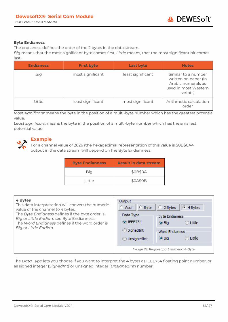
4 Bytes This data interpretation will convert the numeric value of the channel to 4 bytes. The Byte Endianess defines if the byte order is Big or Little Endian: see Byte Endianness. The Word Endianess defines if the word order is Big or Little Endian.
Image 79: Request part numeric: 4-Byte
The Data Type lets you choose if you want to interpret the 4 bytes as IEEE754 floating point number, or as signed integer (SignedInt) or unsigned integer (UnsignedInt) number:
DewesoftX® Serial Com Module V20-1 55/127

DewesoftX® Serial Com Module SOFTWARE USER MANUAL
Data Type Range Min Range Max
IEEE754 -3.4e38 3.4e38
Signed integer -2,147,483,648 2,147,483,647
Unsigned integer 0 4,294,967,295
Text channels For text channels you can specify the output length, the alignment and the fill character. If the length is set to Auto, then the channel of the text value will be output as it is. If you specify a number for the Length, then:
● If the text is longer than the specified length, it will be truncated. ● If it is shorter, the alignment and fill character are important.
Image 80: Text
Example In this example we will use a Length of 4 and a – as Fill Character.
Channel Text Alignment Output
abcdef Left abcd
Right cdef
ab Left ab--
Right --ab
Channel References DewesoftX® does not use the channel names to reference channels, but some internal index numbers. This makes a unique identification of each channel possible – even if some channels have the same name. Moreover, you can rename a channel without breaking any references to it. Therefore, channel references may become invalid: e.g. when you set a channel to Unused, delete a referenced channel or if
DewesoftX® Serial Com Module V20-1 56/127

DewesoftX® Serial Com Module SOFTWARE USER MANUAL
you copy a request to another setup where the referenced channel does not exist (or is Unused in that setup). Renaming referenced channels is no problem.
First, we create a Math channel with the name MathCh1.
Then we create a request with a request part which uses the MathCh1 as reference:
Image 81: Create channel MathCh1
Image 82: Create Request
When we now look at the Requests we can see that the request is valid (and references the Math channel).
Image 83: Valid reference
DewesoftX® Serial Com Module V20-1 57/127

DewesoftX® Serial Com Module SOFTWARE USER MANUAL
We can now go to the Math channel setup and rename the referenced Math channel: e.g. to MathCh1-Renamed.
When we now go back to the Requests, we can see that everything is still valid and that the new channel name is shown in the channel list:
Image 84: Rename Math channel
Image 85: Renamed channel
Deleting a referenced channel
Let's go to the Math channel setup and delete the channel MathCh1 that we have created before and which is still referenced by our request.
Image 86: Delete channel MathCh1-Renamed
When we now go back to the Requests we can see that the request shows an error. When we open the request and then the request part we can see the error message: channel “MathCh1-Renamed” not found (see (1) in Image 87). You must select another existing channel to make the message disappear. Note: if the error message is too long to be displayed, it will be truncated - you will see the ellipses … at the end of the message. If you hover the mouse over the message, a tooltip will appear and show the complete message (see (2) in Image 87)
Image 87: Invalid channel reference
Note: even if we now recreate a new channel with the same name MathCh1, the error message will still be there (since the new Math channel will have another unique index as the original channel: see chapter Channel References for details).
DewesoftX® Serial Com Module V20-1 58/127

DewesoftX® Serial Com Module SOFTWARE USER MANUAL
7.3.3. Request Part Crc When you click the CRC button in the toolbar, you can add a check value calculation. The result of the calculation will be added to the request that we send to the Serial device, so that the device can check if the data is still valid when it is being received. The CRC definition is the same as for the Responses: please refer to chapter 7.3.2 CRC on page 66. Also note that you can define for each response part if the Prefix, Value and/or Postfix are used for the CRC calculation: see chapter Use for CRC.
DewesoftX® Serial Com Module V20-1 59/127
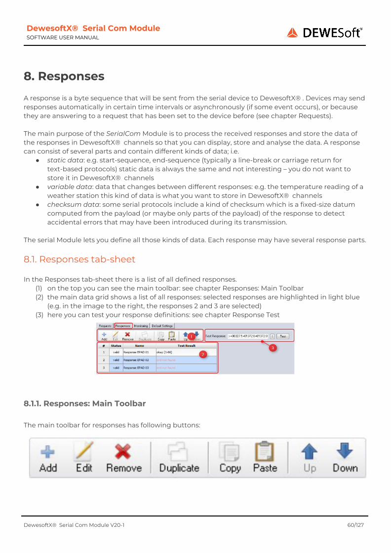
DewesoftX® Serial Com Module SOFTWARE USER MANUAL
8. Responses A response is a byte sequence that will be sent from the serial device to DewesoftX® . Devices may send responses automatically in certain time intervals or asynchronously (if some event occurs), or because they are answering to a request that has been set to the device before (see chapter Requests). The main purpose of the SerialCom Module is to process the received responses and store the data of the responses in DewesoftX® channels so that you can display, store and analyse the data. A response can consist of several parts and contain different kinds of data; i.e.
● static data: e.g. start-sequence, end-sequence (typically a line-break or carriage return for text-based protocols) static data is always the same and not interesting – you do not want to store it in DewesoftX® channels
● variable data: data that changes between different responses: e.g. the temperature reading of a weather station this kind of data is what you want to store in DewesoftX® channels
● checksum data: some serial protocols include a kind of checksum which is a fixed-size datum computed from the payload (or maybe only parts of the payload) of the response to detect accidental errors that may have been introduced during its transmission.
The serial Module lets you define all those kinds of data. Each response may have several response parts.
8.1. Responses tab-sheet In the Responses tab-sheet there is a list of all defined responses.
(1) on the top you can see the main toolbar: see chapter Responses: Main Toolbar (2) the main data grid shows a list of all responses: selected responses are highlighted in light blue
(e.g. in the image to the right, the responses 2 and 3 are selected) (3) here you can test your response definitions: see chapter Response Test
8.1.1. Responses: Main Toolbar The main toolbar for responses has following buttons:
DewesoftX® Serial Com Module V20-1 60/127
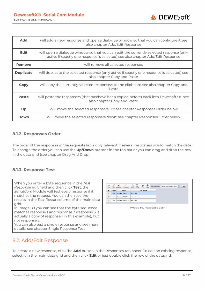
DewesoftX® Serial Com Module SOFTWARE USER MANUAL
Add will add a new response and open a dialogue window so that you can configure it see also chapter Add/Edit Response
Edit will open a dialogue window so that you can edit the currently selected response (only active if exactly one response is selected) see also chapter Add/Edit Response
Remove will remove all selected responses
Duplicate will duplicate the selected response (only active if exactly one response is selected) see also chapter Copy and Paste
Copy will copy the currently selected response/s to the clipboard see also chapter Copy and Paste
Paste will paste the response/s (that has/have been copied before) back into DewesoftX® see also chapter Copy and Paste
Up Will move the selected response/s up: see chapter Responses Order below
Down Will move the selected response/s down: see chapter Responses Order below
8.1.2. Responses Order The order of the responses in the requests list is only relevant if several responses would match the data. To change the order you can use the Up/Down buttons in the toolbar or you can drag and drop the row in the data grid (see chapter Drag And Drop).
8.1.3. Response Test
When you enter a byte sequence in the Test Response edit field and then click Test, the SerialCom Module will test every response if it matches the request. You can then see the results in the Test Result column of the main data grid. In Image 88 you can see that the byte sequence matches response 1 and response 3 (response 3 is actually a copy of response 1 in this example), but not response 2. You can also test a single response and see more details: see chapter Single Response Test
Image 88: Response Test
8.2. Add/Edit Response To create a new response, click the Add button in the Responses tab-sheet. To edit an existing response, select it in the main data grid and then click Edit or just double click the row of the datagrid.
DewesoftX® Serial Com Module V20-1 61/127
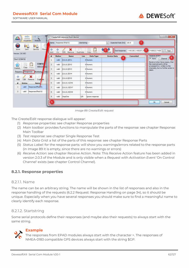
DewesoftX® Serial Com Module SOFTWARE USER MANUAL
Image 89: Create/Edit request
The Create/Edit response dialogue will appear:
(1) Response properties: see chapter Response properties (2) Main toolbar: provides functions to manipulate the parts of the response: see chapter Response:
Main Toolbar (3) Test response: see chapter Single Response Test (4) Main Data Grid: a list of the parts of this response: see chapter Response Parts (5) Status Label: for the response parts: will show you warnings/errors related to the response parts
(in Image 89 it is empty, since there are no warnings or errors) (6) Receive Action: see chapter Receive Action. Note: This Receive Action feature has been added in
version 2.0.3 of the Module and is only visible when a Request with Activation Event 'On Control Channel' exists (see chapter Control Channel).
8.2.1. Response properties
8.2.1.1. Name The name can be an arbitrary string. The name will be shown in the list of responses and also in the response handling of the requests (6.2.2 Request: Response Handling on page 34), so it should be unique. Especially when you have several responses you should make sure to find a meaningful name to clearly identify each response.
8.2.1.2. Startstring Some serial protocols define their responses (and maybe also their requests) to always start with the same string.
Example The responses from EPAD modules always start with the character >. The responses of NMEA-0183 compatible GPS devices always start with the string $GP.
DewesoftX® Serial Com Module V20-1 62/127
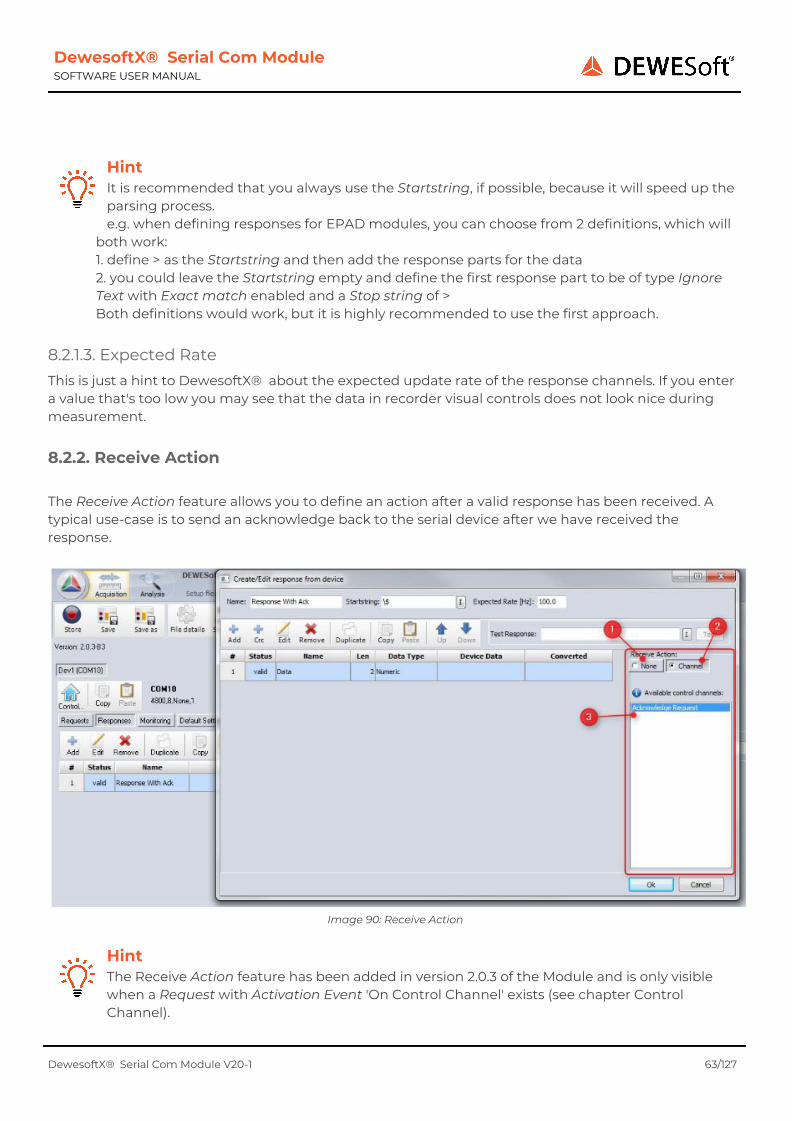
DewesoftX® Serial Com Module SOFTWARE USER MANUAL
Hint It is recommended that you always use the Startstring, if possible, because it will speed up the parsing process. e.g. when defining responses for EPAD modules, you can choose from 2 definitions, which will
both work: 1. define > as the Startstring and then add the response parts for the data 2. you could leave the Startstring empty and define the first response part to be of type Ignore Text with Exact match enabled and a Stop string of > Both definitions would work, but it is highly recommended to use the first approach.
8.2.1.3. Expected Rate This is just a hint to DewesoftX® about the expected update rate of the response channels. If you enter a value that's too low you may see that the data in recorder visual controls does not look nice during measurement.
8.2.2. Receive Action The Receive Action feature allows you to define an action after a valid response has been received. A typical use-case is to send an acknowledge back to the serial device after we have received the response.
Image 90: Receive Action
Hint The Receive Action feature has been added in version 2.0.3 of the Module and is only visible when a Request with Activation Event 'On Control Channel' exists (see chapter Control Channel).
DewesoftX® Serial Com Module V20-1 63/127
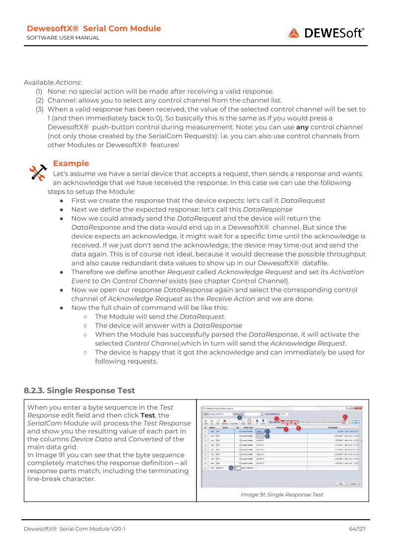
DewesoftX® Serial Com Module SOFTWARE USER MANUAL
Available Actions:
(1) None: no special action will be made after receiving a valid response. (2) Channel: allows you to select any control channel from the channel list. (3) When a valid response has been received, the value of the selected control channel will be set to
1 (and then immediately back to 0). So basically this is the same as if you would press a DewesoftX® push-button control during measurement. Note: you can use any control channel (not only those created by the SerialCom Requests): i.e. you can also use control channels from other Modules or DewesoftX® features!
Example Let's assume we have a serial device that accepts a request, then sends a response and wants an acknowledge that we have received the response. In this case we can use the following
steps to setup the Module: ● First we create the response that the device expects: let's call it DataRequest ● Next we define the expected response: let's call this DataResponse ● Now we could already send the DataRequest and the device will return the
DataResponse and the data would end up in a DewesoftX® channel. But since the device expects an acknowledge, it might wait for a specific time until the acknowledge is received. If we just don't send the acknowledge, the device may time-out and send the data again. This is of course not ideal, because it would decrease the possible throughput and also cause redundant data values to show up in our DewesoftX® datafile.
● Therefore we define another Request called Acknowledge Request and set its Activation Event to On Control Channel exists (see chapter Control Channel).
● Now we open our response DataResponse again and select the corresponding control channel of Acknowledge Request as the Receive Action and we are done.
● Now the full chain of command will be like this: ○ The Module will send the DataRequest. ○ The device will answer with a DataResponse ○ When the Module has successfully parsed the DataResponse, it will activate the
selected Control Channel,which in turn will send the Acknowledge Request. ○ The device is happy that it got the acknowledge and can immediately be used for
following requests.
8.2.3. Single Response Test
When you enter a byte sequence in the Test Response edit field and then click Test, the SerialCom Module will process the Test Response and show you the resulting value of each part in the columns Device Data and Converted of the main data grid. In Image 91 you can see that the byte sequence completely matches the response definition – all response parts match, including the terminating line-break character.
Image 91: Single Response Test
DewesoftX® Serial Com Module V20-1 64/127

DewesoftX® Serial Com Module SOFTWARE USER MANUAL
(1) The Startstring (in this case just the character >) is directly at the beginning of the Test Response (2) The first data field of the request is defined as an 8 byte ASCII sequence interpreted as a number:
in this case the characters +00027.5 match this definition. The Device Data column shows the original byte-sequence that matches the response part (+00027.5). And the Converted column gives more detailed information about the final value, as it also shows how the scale and offset affect the final value (27.5) that will be stored in the DewesoftX® data channel.
(3) The second data field : Device Data: +01372.0, Converted 1,372. The procedure for the following response parts is the same as in 2 and 3…
(4) The last character of the Test Response is the carriage return. This matches the last response part in this response definition.
See also: chapter Response Test See also: chapter CRC for testing a checksum
8.2.4. Response: Main Toolbar
Add will add a new response part and open a dialogue window so that you can configure it see also chapter Response Parts
Crc Cyclic Redundancy Check: allows you to add a checksum definition: see chapter CRC
Edit will open a dialogue window so that you can edit the currently selected response part (only active if exactly one response part is selected)
see also chapter Response Parts
Remove will remove all selected response parts
Duplicate will duplicate the selected response part (only active if exactly one response part is selected)
see also chapter Copy and Paste
Copy will copy the currently selected response part to the clipboard see also chapter Copy and Paste
Paste will paste the response part/s (that have been copied before) back into DewesoftX® see also chapter Copy and Paste
Up Will move the selected response part/s up
Down Will move the selected response part/s down
DewesoftX® Serial Com Module V20-1 65/127

DewesoftX® Serial Com Module SOFTWARE USER MANUAL
To change the order you can use the Up/Down buttons in the toolbar or you can drag and drop the row in the data grid (see chapter Drag And Drop).
8.2.5. Response: Main Data Grid In the main data grid of the response you can see a list of all response parts.
Image 92: Response: Main Data Grid
The main data grid has the following columns:
● #: just a unique index number ● Status: the validation status of the response part: see chapter Warnings and Errors ● Name: The Name is the name of the response part and can be an arbitrary string. The name will
be shown in the list of response parts, so it should be unique. Especially when you have several response parts you should make sure to find a meaningful name to clearly identify each response part. Moreover the name will be used for the corresponding DewesoftX® channels (if the response part has a channel; i.e. response parts of type Text (see chapter Text) or Numeric (chapter Numeric).
● Len: Will show the End Definition (see (2) in chapter General response parts) of the response part. If the End Definition is Fixed Length, the number of bytes will be shown (see request part 7 in Image 92) If the End Definition is Stop string, the Stop string will be shown (see request parts 1-6 in Image 92)
● Data Type: will show the selected Response Part Data Handler of the response part(see chapter General response parts). Device Data: only used when you test a response: see chapter Single Response Test
● Converted: only used when you test a response: see chapter Single Response Test
DewesoftX® Serial Com Module V20-1 66/127

DewesoftX® Serial Com Module SOFTWARE USER MANUAL
8.3. Response Parts The response parts actually define the format of the data that will be received from the serial device, so it should be obvious that each response should have at least one request part. If you have several response parts, the order is very important and must be matched by the received data. You can also define a special response part named CRC for handling a checksum (see chapter CRC).
8.3.1. General response parts
You can create a new general response part by clicking the Add button of the main toolbar in the Create/Edit response from device dialogue (see chapter Response: Main Toolbar). Then the Create/Edit response part dialogue will be opened: see Image 93.
Image 93: Create/Edit response part dialogue
(1) Name and Description:
The Name is the name of the response part and can be an arbitrary string. The name will be shown in the list of response parts, so it should be unique. Especially when you have several response parts you should make sure to find a meaningful name to clearly identify each response part. Moreover the name and description will be used for the corresponding DewesoftX® channels (if the response part has a channel; i.e. response parts of type Text (see chapter Text) or Numeric (chapter Numeric).
(2) End Definition: the end definition is used to define the length of the response part. Fixed Length: if the size of the response part is fixed; i.e. always has the same number of bytes (e.g. room temperature values may be represented by a single byte) Stop string: if the response part always ends with the same characters (e.g. ; in a list of comma separated values)
(3) Checksum: let's you specify if the value/Stop string of this response part will be used for the calculation of the checksum: see also chapter CRC
(4) BinHex encoding: see chapter Response Part: BinHex Encoding (5) Response Part Data Handler Selection: here you can specify how to interpret the data of this
response part Ignore Response: the data will be ignored: see chapter Ignore response on page Text: the data will be interpreted as text: see chapter Text Numeric: the data will be interpreted as a number: see chapter Numeric
DewesoftX® Serial Com Module V20-1 67/127

DewesoftX® Serial Com Module SOFTWARE USER MANUAL
(6) Response Part Data Handler Settings: will show detailed settings which are different depending
on the Response Part Data Handler Selection.
8.3.1.1. Response Part: BinHex Encoding When activated, every pair of received bytes will be converted from the BinHex encoded format to a single byte.
Example Let's take the following 2 received bytes $32 $41 (#50 #65). The ASCII codes of the 2 bytes are 2 and A. These codes are now interpreted as a single hexadecimal byte: $2A. So the result of the
BinHex conversion of $32 $41 is $2A.
Note: when you activate the BinHex encoding, the encoding is the first thing that will be done when the bytes are received. That means that when you enter a fixed length of 4 bytes for the End Definition, you will only have 2 Bytes available for the numeric conversion: see Image 94. When you select Stop string for the End Definition, then you must make sure that the number of bytes until the stop string is even. If not, the BinHex encoding cannot be applied and the data is invalid.
Image 94: Response Part: BinHex Encoding
8.3.1.2. Ignore response
There might be parts in the response that are not interesting for you at all; i.e. you do not want to store that data in any DewesoftX® channel.
Image 95: Ignore response
Example If you are not interested in the 1st part (time information – 081836 in the example below) of a GPRMC sentence: $GPRMC,081836,A,3751.65,S,14507.36,E,000.0,360.0,130998,011.3,E*62\CR\LF
then you could define the beginning $GPRMC, as the Startstring of the response, and the first part could be defined as type Ignore response with the stop string. Then this response part would match the data (081836,), but it would be ignored – Nevertheless, the parsed value could still be used for the checksum calculation.
Exact Match
DewesoftX® Serial Com Module V20-1 68/127

DewesoftX® Serial Com Module SOFTWARE USER MANUAL
If Exact Match is activated, then the response part must exactly match the Stop string otherwise data before the Stop string will also be consumed. Note: Exact Match is only enabled when the End Definition is Stop string (for a Fixed Length it does not make sense, because the fixed length always matches exactly).
Example Let's say we have defined the $ as Starstring of the response. And the first part is of type Ignore response with the Stop string C, then we would get these results for the response part:
Data Exact Match activated Result for response part one
$CDEF
C
C
$ABCDEF
No match
ABC
8.3.1.3. Text
When you choose the Response Part Data Handler Text, then the received byte sequence will be interpreted as ASCII characters and will be stored in a DewesoftX® string channel.
Image 96: Text
Length: defines the Length of the string channel. If the data is longer than the specified length, the text will be truncated. You should the lowest possible length, because otherwise it will just increase the size of the DewesoftX® file without giving you more information. Stored: if this is deactivated, the data of the channel can be displayed in Measurement mode, but will not be stored in the DewesoftX® data file; i.e. it will not be available in Analyze mode when you reload the data file.
DewesoftX® Serial Com Module V20-1 69/127

DewesoftX® Serial Com Module SOFTWARE USER MANUAL
8.3.1.4. Numeric The Response Part Data Handler Numeric, is the most interesting one, because you usually want to use the data as a number that you can display, calculate and analyse easily. Depending on the End Definition settings there are different data interpretations available:
Interpretation name Available if See also
Numeric Data Ascii Interpretation
always chapter Numeric Data Ascii Interpretation
One Byte Numeric Data Interpretation
Fixed Length is 1 or Fixed Length is 2 (BinHex
encoding)
chapter Numeric Data Ascii Interpretation
Two Byte Numeric Data Interpretation
Fixed Length is 1 or Fixed Length is 2 (BinHex
encoding)
chapter Two Byte Numeric Data Interpretation
Four Byte Numeric Data Interpretation
Fixed Length is 4 or Fixed Length is 8 (BinHex
encoding)
chapter Four Byte Numeric Data Interpretation
Numeric Data Ascii Interpretation
Image 97: Numeric: Ascii
DewesoftX® Serial Com Module V20-1 70/127
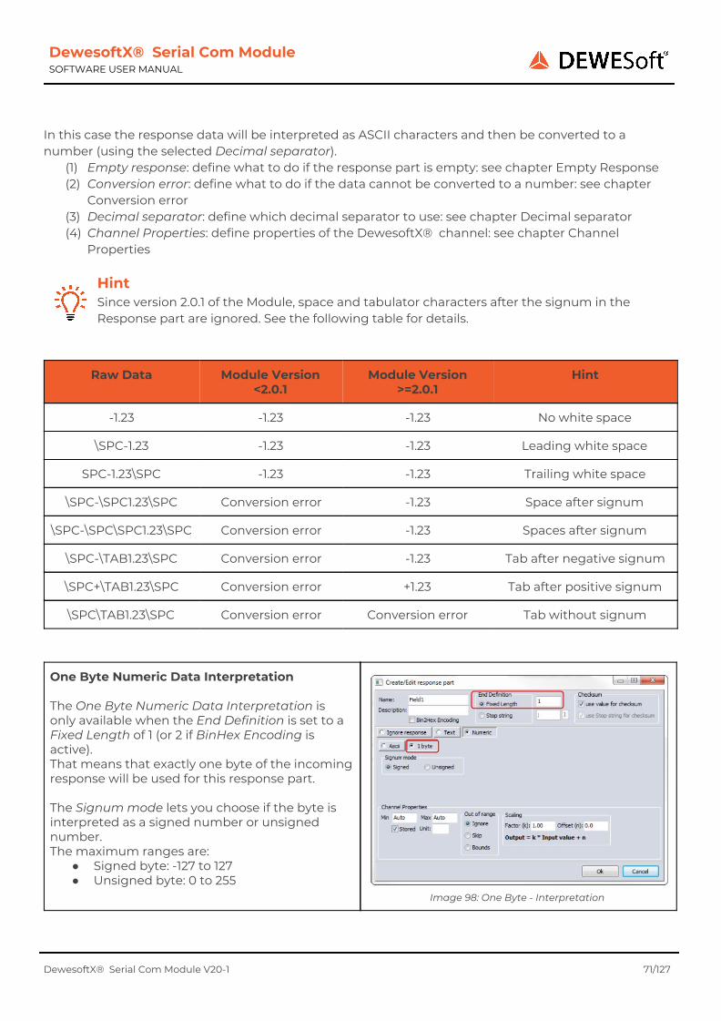
DewesoftX® Serial Com Module SOFTWARE USER MANUAL
In this case the response data will be interpreted as ASCII characters and then be converted to a number (using the selected Decimal separator).
(1) Empty response: define what to do if the response part is empty: see chapter Empty Response (2) Conversion error: define what to do if the data cannot be converted to a number: see chapter
Conversion error (3) Decimal separator: define which decimal separator to use: see chapter Decimal separator (4) Channel Properties: define properties of the DewesoftX® channel: see chapter Channel
Properties
Hint Since version 2.0.1 of the Module, space and tabulator characters after the signum in the Response part are ignored. See the following table for details.
Raw Data Module Version <2.0.1
Module Version >=2.0.1
Hint
-1.23 -1.23 -1.23 No white space
\SPC-1.23 -1.23 -1.23 Leading white space
SPC-1.23\SPC -1.23 -1.23 Trailing white space
\SPC-\SPC1.23\SPC Conversion error -1.23 Space after signum
\SPC-\SPC\SPC1.23\SPC Conversion error -1.23 Spaces after signum
\SPC-\TAB1.23\SPC Conversion error -1.23 Tab after negative signum
\SPC+\TAB1.23\SPC Conversion error +1.23 Tab after positive signum
\SPC\TAB1.23\SPC Conversion error Conversion error Tab without signum
One Byte Numeric Data Interpretation The One Byte Numeric Data Interpretation is only available when the End Definition is set to a Fixed Length of 1 (or 2 if BinHex Encoding is active). That means that exactly one byte of the incoming response will be used for this response part. The Signum mode lets you choose if the byte is interpreted as a signed number or unsigned number. The maximum ranges are:
● Signed byte: -127 to 127 ● Unsigned byte: 0 to 255
Image 98: One Byte - Interpretation
DewesoftX® Serial Com Module V20-1 71/127
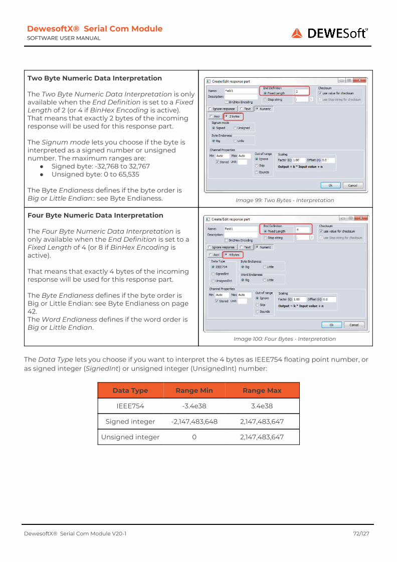
DewesoftX® Serial Com Module SOFTWARE USER MANUAL
Two Byte Numeric Data Interpretation The Two Byte Numeric Data Interpretation is only available when the End Definition is set to a Fixed Length of 2 (or 4 if BinHex Encoding is active). That means that exactly 2 bytes of the incoming response will be used for this response part. The Signum mode lets you choose if the byte is interpreted as a signed number or unsigned number. The maximum ranges are:
● Signed byte: -32,768 to 32,767 ● Unsigned byte: 0 to 65,535
The Byte Endianess defines if the byte order is Big or Little Endian:: see Byte Endianess.
Image 99: Two Bytes - Interpretation
Four Byte Numeric Data Interpretation The Four Byte Numeric Data Interpretation is only available when the End Definition is set to a Fixed Length of 4 (or 8 if BinHex Encoding is active). That means that exactly 4 bytes of the incoming response will be used for this response part. The Byte Endianess defines if the byte order is Big or Little Endian: see Byte Endianess on page 42. The Word Endianess defines if the word order is Big or Little Endian.
Image 100: Four Bytes - Interpretation
The Data Type lets you choose if you want to interpret the 4 bytes as IEEE754 floating point number, or as signed integer (SignedInt) or unsigned integer (UnsignedInt) number:
Data Type Range Min Range Max
IEEE754 -3.4e38 3.4e38
Signed integer -2,147,483,648 2,147,483,647
Unsigned integer 0 2,147,483,647
DewesoftX® Serial Com Module V20-1 72/127

DewesoftX® Serial Com Module SOFTWARE USER MANUAL
8.3.1.5. Exception Handling Of Response Parts If an exceptional condition occurs when processing the data for a response part, you can define how to handle this situation.
Example We will now define a simple protocol and take a look at the options you have. Let's say, our protocol always starts with a $ sign and has 3 numeric fields which are terminated
by a ;. e.g. the data-string $1;11;21; would be valid and field one has the value 1, field two the value 11 and field three the value 21. The setup in the SerialCom Module for this protocol is very easy. We use \$ as Startstring of the response and create a response part named Field1 with the stop string ; and choose the Response Part Data Handler Numeric. Then we click duplicate and change the name of the second response part to Field2 and then we do the same again to create a response part Field3.
Image 101: Exception Handling Setup
Now we will take a look at the exceptional cases: Empty Response Will define what to do if the response part is empty. This is only active if the End Definition Stop string is selected. Let's assume we receive the following 3 responses (the start strings are bold for clarity): $1;11;21;$2;;22;$3;13;23; When we look at the 2nd response ($2;;22;), we can see that the 2nd field is empty (2 colons follow each other without any data in between). In this case you can choose to skip this response part or use the Min/Max value instead.
DewesoftX® Serial Com Module V20-1 73/127

DewesoftX® Serial Com Module SOFTWARE USER MANUAL
Skip the response part In Image 105 you can see what happens if the data point is skipped – the data (Field2 of response 2 – received at the time 6.061) is just missing, all other fields of the response are there (Field1 has the value 2 and Field3 has the value 22).
Image 102: Skipped Response Part
Use Min/Max Instead of skipping the response you can also choose to use the Min or Max value instead. To do this, we will change the Empty response handling of Field2 and enter a Min value of -13.
When we now take a look at the received data, we can see that the empty field in response 2 has now been replaced with the specified Min value of -13.
Image 103: Empty Response: Min
Image 104: Empty Response: Min Data
Hint You should not use Auto when you use Min/Max, because the missing response would be replaced with -INF (negative infinity) and +INF (positive infinity). This could cause errors in the displays or in mathematical calculations.
DewesoftX® Serial Com Module V20-1 74/127
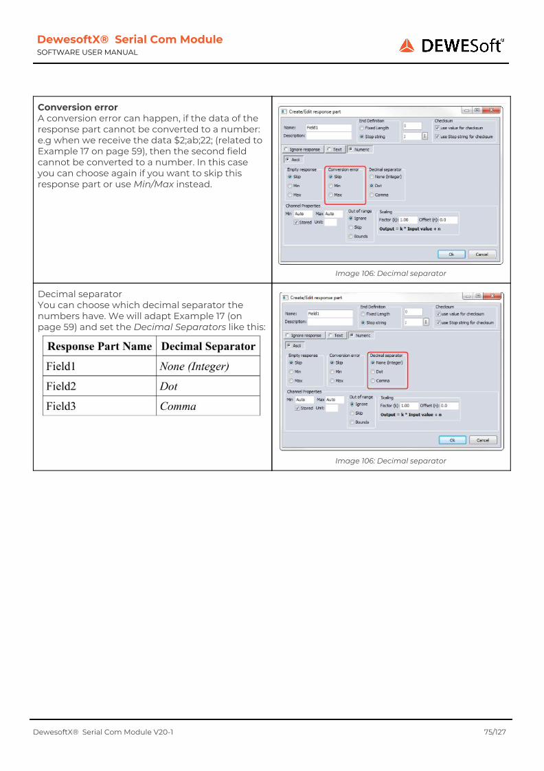
DewesoftX® Serial Com Module SOFTWARE USER MANUAL
Conversion error A conversion error can happen, if the data of the response part cannot be converted to a number: e.g when we receive the data $2;ab;22; (related to Example 17 on page 59), then the second field cannot be converted to a number. In this case you can choose again if you want to skip this response part or use Min/Max instead.
Image 106: Decimal separator
Decimal separator You can choose which decimal separator the numbers have. We will adapt Example 17 (on page 59) and set the Decimal Separators like this:
Image 106: Decimal separator
DewesoftX® Serial Com Module V20-1 75/127

DewesoftX® Serial Com Module SOFTWARE USER MANUAL
Now let's take a look at the results, when we receive these 3 responses: $1;11;21;$2.2;12.3;22,3;$2,2;12,3;22.3;
● Response 1: $1;11;21; all 3 fields are valid – note that the selected decimal separator may be missing (e.g. Field2 has Decimal Separator Dot, but the data does not contain a .)
● Response 2: $2.2;12.3;22,3; Field1 (2.2) is invalid – we have specified Decimal Separator None (Integer), but the data contains a . as a decimal separator. The other 2 fields are valid and they contain the specified decimal separator.
● Response 3: $2,2;12,3;22.3; is completely missing, since all fields are invalid: Field1 contains a , as decimal separator, but we have specified Decimal Separator None (Integer). Field2 contains a , as decimal separator, but we have specified Decimal Separator Dot. Field3 contains a . as decimal separator, but we have specified Decimal Separator Comma.
Image 107: Decimal Separator Data
Hint When you have selected Dot as Decimal Separator, then the data may also contain optional Commas as thousand separators: e.g. 1,234,567.12 is valid. When you have selected Comma as Decimal Separator, then the data may also contain optional Dots as thousand separators: e.g.
1.234.567,12 is valid.
8.3.1.6. Channel Properties
Here you can define general properties of the numeric channels.
● Min/Max: here you can define a valid range of the numeric data: see chapter Out Of Range Handling for details The values can also be used in the Empty response and Conversion error handling: see chapter Exception Handling Of Response Parts. And the values will also be used as the default range when you assign the channel to a visual control (e.g. to a Recorder) in the measure mode of DewesoftX® .
● Stored: if the data will be stored in the DewesoftX® data file or not.
● Unit: the unit that will be displayed for this channel: e.g. A, V, °C, etc.
● Out of Range: here you can define what
Image 108: Channel Properties
DewesoftX® Serial Com Module V20-1 76/127
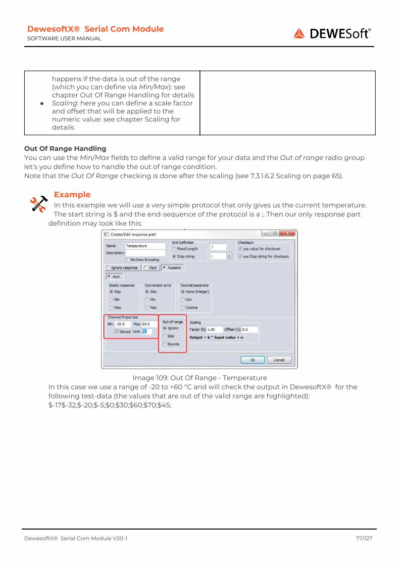
DewesoftX® Serial Com Module SOFTWARE USER MANUAL
happens if the data is out of the range (which you can define via Min/Max): see chapter Out Of Range Handling for details
● Scaling: here you can define a scale factor and offset that will be applied to the numeric value: see chapter Scaling for details
Out Of Range Handling You can use the Min/Max fields to define a valid range for your data and the Out of range radio group let's you define how to handle the out of range condition. Note that the Out Of Range checking is done after the scaling (see 7.3.1.6.2 Scaling on page 65).
Example In this example we will use a very simple protocol that only gives us the current temperature. The start string is $ and the end-sequence of the protocol is a ;. Then our only response part
definition may look like this:
Image 109: Out Of Range - Temperature
In this case we use a range of -20 to +60 °C and will check the output in DewesoftX® for the following test-data (the values that are out of the valid range are highlighted): $-17$-32;$-20;$-5;$0;$30;$60;$70;$45;
DewesoftX® Serial Com Module V20-1 77/127

DewesoftX® Serial Com Module SOFTWARE USER MANUAL
Out Of Range: Ignore In this case, the Out Of Range condition will be ignored; i.e. the data that is out of the specified range will still be used: in our example data the values -32 °C and +70 °C are out of range, but will still show up in the DewesoftX® data channel: see Image 111. So the only reason why you would specify Min/Max and use the Out Of Range setting Ignore, is that the Min/Max values will automatically be used as Min/Max range for the DewesoftX® channel: i.e. when you assign the channel to a recorder display, the initial range will be set correctly – see Image 110
Image 110: Recorder: Initial Range
Image 111: Out Of Range: Ignore
Out Of Range: Skip In this case, data that is Out Of Range will be skipped (see also Skip the response part).
You can see in Image 113 that the data that is out of range (in our example data the values -32 °C and +70 °C) will just not show up in the DewesoftX® channel – they are skipped (compare this to Image 111 above).
DewesoftX® Serial Com Module V20-1 78/127
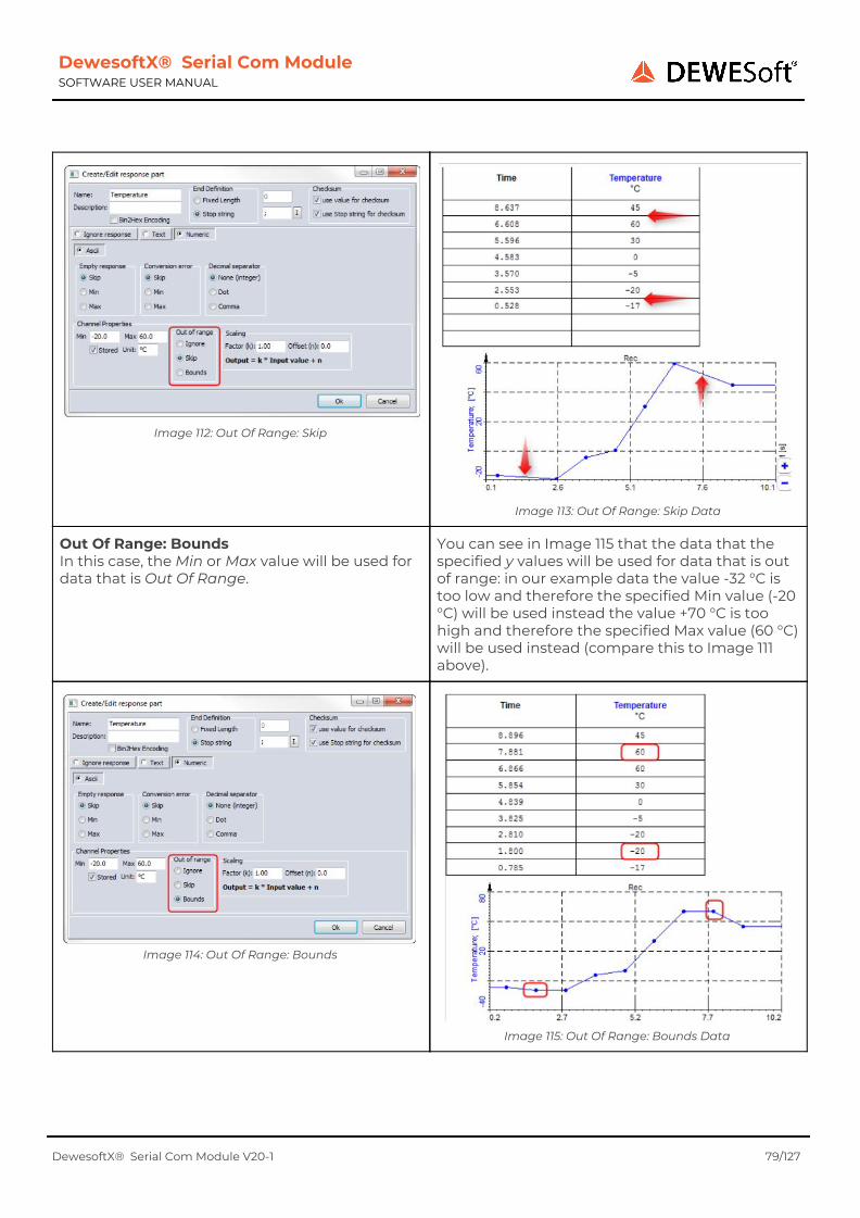
DewesoftX® Serial Com Module SOFTWARE USER MANUAL
Image 112: Out Of Range: Skip
Image 113: Out Of Range: Skip Data
Out Of Range: Bounds In this case, the Min or Max value will be used for data that is Out Of Range.
You can see in Image 115 that the data that the specified y values will be used for data that is out of range: in our example data the value -32 °C is too low and therefore the specified Min value (-20 °C) will be used instead the value +70 °C is too high and therefore the specified Max value (60 °C) will be used instead (compare this to Image 111 above).
Image 114: Out Of Range: Bounds
Image 115: Out Of Range: Bounds Data
DewesoftX® Serial Com Module V20-1 79/127
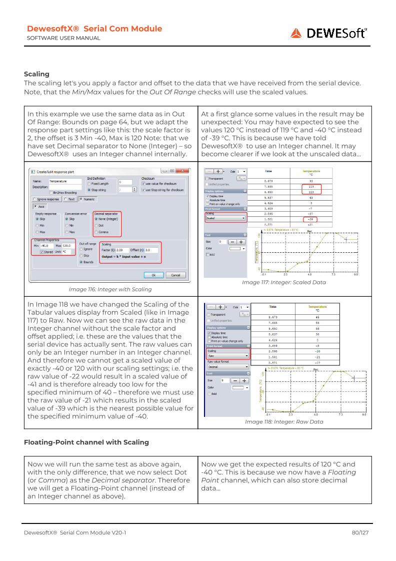
DewesoftX® Serial Com Module SOFTWARE USER MANUAL
Scaling The scaling let's you apply a factor and offset to the data that we have received from the serial device. Note, that the Min/Max values for the Out Of Range checks will use the scaled values.
In this example we use the same data as in Out Of Range: Bounds on page 64, but we adapt the response part settings like this: the scale factor is 2, the offset is 3 Min -40, Max is 120 Note: that we have set Decimal separator to None (Integer) – so DewesoftX® uses an Integer channel internally.
At a first glance some values in the result may be unexpected: You may have expected to see the values 120 °C instead of 119 °C and -40 °C instead of -39 °C. This is because we have told DewesoftX® to use an Integer channel. It may become clearer if we look at the unscaled data...
Image 116: Integer with Scaling
Image 117: Integer: Scaled Data
In Image 118 we have changed the Scaling of the Tabular values display from Scaled (like in Image 117) to Raw. Now we can see the raw data in the Integer channel without the scale factor and offset applied; i.e. these are the values that the serial device has actually sent. The raw values can only be an Integer number in an Integer channel. And therefore we cannot get a scaled value of exactly -40 or 120 with our scaling settings; i.e. the raw value of -22 would result in a scaled value of -41 and is therefore already too low for the specified minimum of 40 – therefore we must use the raw value of -21 which results in the scaled value of -39 which is the nearest possible value for the specified minimum value of -40.
Image 118: Integer: Raw Data
Floating-Point channel with Scaling
Now we will run the same test as above again, with the only difference, that we now select Dot (or Comma) as the Decimal separator. Therefore we will get a Floating-Point channel (instead of an Integer channel as above).
Now we get the expected results of 120 °C and -40 °C. This is because we now have a Floating Point channel, which can also store decimal data...
DewesoftX® Serial Com Module V20-1 80/127

DewesoftX® Serial Com Module SOFTWARE USER MANUAL
Image 119: Floating Point with Scaling
Image 120: Floating Point: Scaled Data
In the Raw data view, we can see that we now can store floating point values and can therefore get the desired results for the Min/Max values: e.g. 58.5 which relates to the scaled value of 120.
Image 121: Floating Point: Raw Data
8.3.2. CRC
Note: the CRC handling has changed a lot in version 2.1.0 of the Module: see also chapter Update to V2.1.0. You can create a new CRC response part by clicking the CRC button (1) of the main toolbar in the Create/Edit response from device dialogue (see 7.2.4 Response: Main Toolbar on page 52). Each response can contain a maximum of one CRC part: when you have already added a CRC the CRC button will be disabled. An existing CRC will show up in the Response part list (2) and can be edited like any other response part. Note: since version 2.1.0 the CRC calculation can also use parts that are ordered after the CRC part.
Image 122: Check Value Definition
DewesoftX® Serial Com Module V20-1 81/127

DewesoftX® Serial Com Module SOFTWARE USER MANUAL
Name and Description (3) are arbitrary strings for the CRC-response part: You should define meaningful values. The Test (4) allows you to test the CRC calculation. When you press the Calculate button , the data in the Test input field will be used to calculate the Check value with the currently selected settings (7). The calculated value will be written to the output field (right to the Calculate button). When there is an error (e.g. when you set the Polynom to 0), the error-message will be written to the output field. The actual Check value calculation algorithm and parameters can be set via the Preset drop-down box (6) and the settings (7).
8.3.2.1. Presets Presets are some predefined configurations with well known names: e.g. the NMEA0183 V3 protocol uses an XOR 8 check value calculation and AsciiHex representation. When you select a preset from the drop-down list, the settings (7) will be changed accordingly.
Image 123: Presets
8.3.2.2. Check Value Settings The settings (see 7 in Image 122) define which algorithm (and which parameters) are used for the check value calculation. Sum 8 Each relevant byte of the input data will be added to a Byte variable. The sum may overflow the number range. Sum 16 Each relevant byte of the input data will be added to a variable with the selected Data Type (8 or 16 bit unsigned: see Image 124). The sum may overflow the number range. You can also define the byte order of the result. Sum 32 Each relevant byte of the input data will be added to a variable with the selected Data Type (8, 16 or 32 bit unsigned: see Image 124). The sum may overflow the number range. You can also define the byte/word order of the result.
DewesoftX® Serial Com Module V20-1 82/127

DewesoftX® Serial Com Module SOFTWARE USER MANUAL
Image 124: Data Type Selection
XOR 8 This setting will apply the XOR operator to all input bytes. CRC 8/16/32 This setting will do a cyclic redundancy check and you can define the corresponding parameters. For the multi-bytes sums you can also define the byte/word order.
Representation The representation setting will be applied to the calculated result. You can choose to output the result as bytes directly or to use AsciiHex representation:
Example When the calculation result is $61$04$30$6C , then the Byte representation will result in exactly those 4 bytes. The AsciiHex representation will result in 8 bytes, where each word will
correspond to the ASCII representation of the bytes hexadecimal value: so the result will be the ASCII characters: 6104306C.
8.3.2.3. Check Value data
You can define for each response part separately if its value (and also its Stop string, if the response part has one defined), is used for the checksum calculation: see Image 125.
Image 125: Request Part: Checksum
DewesoftX® Serial Com Module V20-1 83/127

DewesoftX® Serial Com Module SOFTWARE USER MANUAL
In the Response dialogue (Image 126), the Use for Checksum check-box (2) will define if the Startstring (2)of the response ($ in this case) is used for the check value calculation. Since the starting $ in the NMEA-0183 format must not be part of the checksum, the Use for Checksum check-box is deactivated. When you enter a Test Response and then click the Test button (3), you can see in the Converted column of the Checksum part that the CRC calculation was okay. The value in the Device Data column matches your Test response input (3D).
Image 126: Request Part: Checksum
DewesoftX® Serial Com Module V20-1 84/127

DewesoftX® Serial Com Module SOFTWARE USER MANUAL
9. Monitoring
In the Monitoring tab-sheet you can find some monitoring/debug settings. (1) see chapter Monitoring Timeout (2) see chapter Status Channel (3) see chapter Sent requests (4) see chapter Skipped Data Channel (5) see chapter Com Buffer Size (6) see chapter Log received data
Image 127: Monitoring Off
9.1. Monitoring Timeout When you enter a time-out value (in seconds) the SerialCom Module will monitor the COM port and if no data is received in the time-out period, then the COM port will be closed and reopened. Note: it does not matter if the data that is received matches a response definition or not. Before closing the COM port the SerialCom Module will try to send any requests with the Activation Event On Stop (6.2.1 Activation Event on page 31). After reopening the COM port the SerialCom Module will send any requests with the Activation Event On Start (6.2.1 Activation Event on page 31).
Hint This monitoring is usually only useful if you have a true RS232 connection; i.e. a native RS232 port on the PC. It does not work with most virtual COM ports (i.e. some devices can be connected to the PC via
a USB cable and a dedicated software driver will emulate a so called virtual COM port).
9.1.1. Add status message on timeout This check-box will only be enabled if the Monitoring Timeout and the Status Channel are active. If the check-box is activated and a time-out occurs, then a status message will be added to the Status Channel.
9.2. Status Channel You can activate the status channel to get some debug information
Image 128: Status Channel assigned to a tabular values display
Status messages will be written to the Status Channel,
● if: a time-out has occurred: see chapter Monitoring Timeout ● a request is fired, but is already active or already in the queue: see chapter Queueing
DewesoftX® Serial Com Module V20-1 85/127

DewesoftX® Serial Com Module SOFTWARE USER MANUAL
● a request has been skipped: e.g. because it is out of the specified range: see Numeric range
validation ● no data was available for sending the request: see chapter Channel data ● an unexpected error occurred when trying to send the request
The value that you enter in the Status Channel Length edit field is the length of the DewesoftX® string channel; i.e. if you enter a low value, longer messages will be cut off.
9.3. Sent requests
If activated, all sent requests will be written to this string channel.
Image 129: Status Channel assigned to a tabular values
display
The value that you enter in the Status Channel Length edit field is the length of the DewesoftX® string channel; i.e. if the sent request is longer than the entered length, it will be cut off.
9.4. Skipped Data Channel When you activate the Skipped Data Channel, you will see a new text-channel named Skipped Data in the channel list (see Image 130). When we receive data, which does not match any of the defined responses, the bytes will be added to this channel (see column Skipped Data in Image 131). This can be very useful for debugging.
Image 130: Skipped Data: Channel List
Image 131: Skipped Data Channel
DewesoftX® Serial Com Module V20-1 86/127
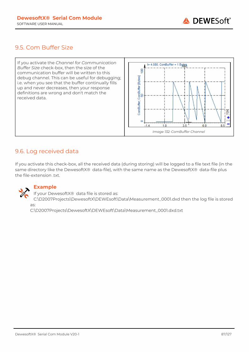
DewesoftX® Serial Com Module SOFTWARE USER MANUAL
9.5. Com Buffer Size
If you activate the Channel for Communication Buffer Size check-box, then the size of the communication buffer will be written to this debug channel. This can be useful for debugging; i.e. when you see that the buffer continually fills up and never decreases, then your response definitions are wrong and don't match the received data.
Image 132: ComBuffer Channel
9.6. Log received data If you activate this check-box, all the received data (during storing) will be logged to a file text file (in the same directory like the DewesoftX® data-file), with the same name as the DewesoftX® data-file plus the file-extension .txt.
Example If your DewesoftX® data file is stored as: C:\D2007Projects\DewesoftX\DEWEsoft\Data\Measurement_0001.dxd then the log file is stored
as: C:\D2007Projects\DewesoftX\DEWEsoft\Data\Measurement_0001.dxd.txt
DewesoftX® Serial Com Module V20-1 87/127

DewesoftX® Serial Com Module SOFTWARE USER MANUAL
10. Advanced Topics
10.1. Copy and Paste You can copy a complete device (see chapter Device Toolbar) responses, response parts, requests and request parts to the clipboard and paste those objects back from the clipboard. The data in the clipboard will have a special XML syntax, so you could even paste the clipboard data into a mail (or text file), send it to another location and paste it into another DewesoftX® setup. Note: when you paste objects from one DewesoftX® setup to another one, you may see warnings and errors after pasting - Examples:
● when you paste the same request twice, you will get a warning because now you have (at least) 2 requests with the same name
● when you paste a request, which has a reference to e.g. a Math channel called 'MathCalc1', into another setup, where this channel does not exist, you will see that this request has an error after pasting
10.2. Drag And Drop
In the data-grids you can use drag and drop to change the order of the rows. Just click on the # column of the row, that you want to move, and keep the left mouse button down. Then move the row up/down (while still holding the left mouse button pressed) - the black horizontal line between the rows will show you where the row will be inserted, when you release the left mouse-button.
Image 133: Drag And Drop Of Rows
10.3. Testing the Module without hardware It is possible to test the Module without actual hardware. This requires the installation of some test-programs.
10.3.1. Null-modem emulator Since there is no serial hardware available, we need to use a program to emulate a COM-port. We will use the program com0com which is open source and freeware: http://com0com.sourceforge.net/
DewesoftX® Serial Com Module V20-1 88/127
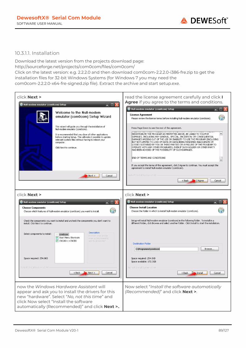
DewesoftX® Serial Com Module SOFTWARE USER MANUAL
10.3.1.1. Installation Download the latest version from the projects download page: http://sourceforge.net/projects/com0com/files/com0com/ Click on the latest version: e.g. 2.2.2.0 and then download com0com-2.2.2.0-i386-fre.zip to get the installation files for 32-bit Windows Systems (for Windows 7 you may need the com0com-2.2.2.0-x64-fre-signed.zip file). Extract the archive and start setup.exe.
click Next >
read the license agreement carefully and click I Agree if you agree to the terms and conditions.
click Next >
click Next >
now the Windows Hardware Assistant will appear and ask you to install the drivers for this new “hardware”. Select “No, not this time” and click Now select “Install the software automatically (Recommended)” and click Next >..
Now select “Install the software automatically (Recommended)” and click Next >.
DewesoftX® Serial Com Module V20-1 89/127
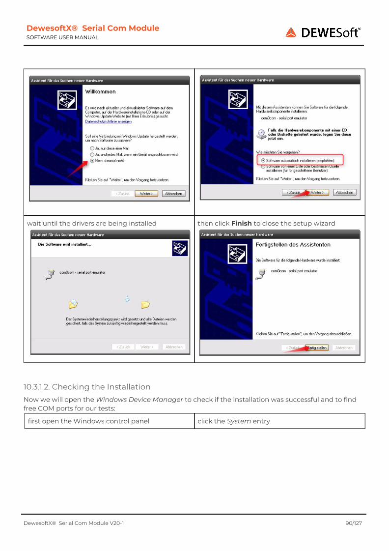
DewesoftX® Serial Com Module SOFTWARE USER MANUAL
wait until the drivers are being installed
then click Finish to close the setup wizard
10.3.1.2. Checking the Installation Now we will open the Windows Device Manager to check if the installation was successful and to find free COM ports for our tests:
first open the Windows control panel click the System entry
DewesoftX® Serial Com Module V20-1 90/127

DewesoftX® Serial Com Module SOFTWARE USER MANUAL
go to the Hardware tab sheet and click the Device Manager button
1) shows all COM and LPT ports on your computer 2) shows the emulated COM ports that we have just installed
DewesoftX® Serial Com Module V20-1 91/127

DewesoftX® Serial Com Module SOFTWARE USER MANUAL
In this case only COM-port COM1 is used on the computer. So we must not use this port for our emulator (we use COM17 and COM18 instead).
10.3.1.3. Renaming the COM Ports The emulator ports are currently called CNCA0 and CNCB0 we will change this to COM17 and COM18 in the next steps:
first start the com0com-Setup program that we have just installed:
Now change the names of the COM-ports:
DewesoftX® Serial Com Module V20-1 92/127

DewesoftX® Serial Com Module SOFTWARE USER MANUAL
After you have changed the names, they appear in blue colour. Press the Apply button to actually apply the changes to your system.
When this has finished the names of the ports will be in black colour again and you can also see the new names in the Windows Device Manager
10.3.2. Data emulator Now we need to write some data on the COM port. We can use the freeware program COM Port Data Emulator. Download the program from here: http://www.aggsoft.com/com-port-emulator/download.htm and start the setup program: asdlemul2.exe.
on the Welcome screen click Next > read the license agreement carefully and if you agree to the terms and conditions, select the 'I accept the agreement' option and click Next >
DewesoftX® Serial Com Module V20-1 93/127

DewesoftX® Serial Com Module SOFTWARE USER MANUAL
keep the default installation location and click Next >
keep the default settings, and click Next >
choose which additional tasks you want and click Next >
check the settings again and click Install to start the installation.
DewesoftX® Serial Com Module V20-1 94/127

DewesoftX® Serial Com Module SOFTWARE USER MANUAL
after the installation has finished, make sure, that the 'Launch COM Port Data Emulator' checkbox is activated click the Finish button
Now the COM Port Data Emulator is started and we will generate some test-data:
in the Device tab-sheet: 1) change the Serial port to 17 and 2) keep the connection settings in mind (we will need them later in DewesoftX® 's hardware setup) the comma separated numbers have the following meaning: Baud Rate, Data Bits, Parity, Stop Bit
then click the Data source tab-sheet: 1. select Text strings for the Data source 2. enter some test-message: e.g. I11.23#0FvariableText i-2.34#11short 3. activate the 'Auto sending interval (ms)' checkbox and change the interval to 1000 ms, so that the test-messages will be sent every second when the settings are okay, press the Start button.
DewesoftX® Serial Com Module V20-1 95/127

DewesoftX® Serial Com Module SOFTWARE USER MANUAL
the application will switch to the Log tab-sheet and show the data that it is now sending to COM port 17 and also some information messages. You can press Stop any time to stop the communication.
The Null-modem emulator (see chapter Null-modem emulator) will receive all messages that the Data emulator sends to COM Port 17 and copy them to COM Port 18.
DewesoftX® Serial Com Module V20-1 96/127

DewesoftX® Serial Com Module SOFTWARE USER MANUAL
10.3.3. Test-data in DewesoftX® Now we start DewesoftX® and check if the test-data is received correctly:
● first open Options... - Settings. Go to the ● Extension tab-sheet and select the Serial
Com Module. At the right side enter the Module properties. COM Port: this must be the COM Port that the Null-modem emulator is sending the output to (in our case we have to choose COM18.
● Baud rate, Stop bits, Data bits and Parity must match the settings that you have selected in the Data emulator setup. In our case: 9600, 1, 8, None
When you are done, press the OK button to leave hardware setup.
Go to Setup files and press the New Setup button to create a new DewesoftX® channel setup.
Now go to channel setup (Ch. setup). You will see which COM port is in use and its communication settings. First we go to the Default Settings and make sure that 'Dot' is selected as default decimal separator:
Now we go to the Responses tabsheet and create our Response definition – just click the Add button:
We can enter a meaningful name for the response and then we click the Add button to enter the first part of our response (note, that you can see an error message at the left bottom of the dialogue, because we have not defined any response part yet).
When we look at our test-message: I11.23#0FvariableText i-2.34#11short we can see that the first char is not very meaningful – we will just skip it and not store it in any DewesoftX® channel. When you have changed the settings like in the image below, press OK to go back to
DewesoftX® Serial Com Module V20-1 97/127
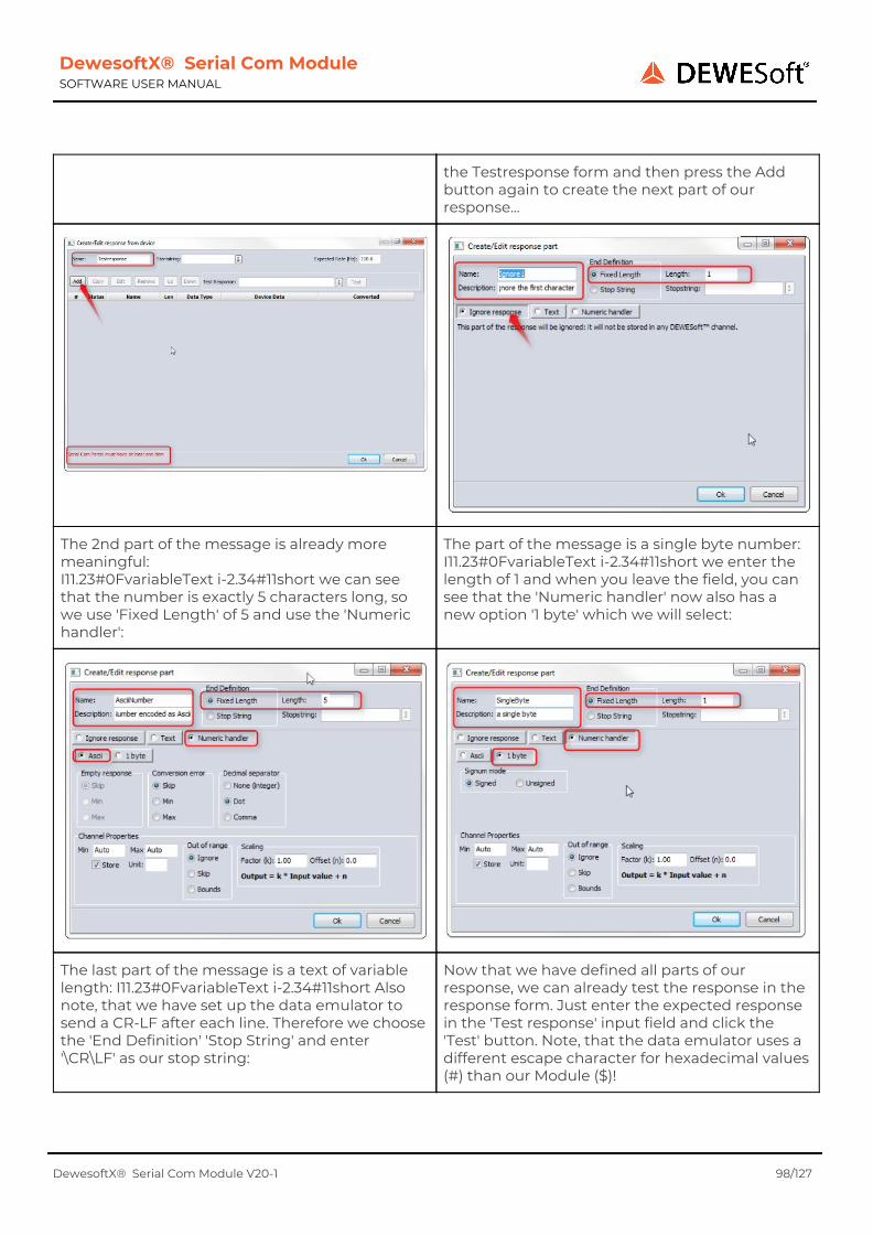
DewesoftX® Serial Com Module SOFTWARE USER MANUAL
the Testresponse form and then press the Add button again to create the next part of our response...
The 2nd part of the message is already more meaningful: I11.23#0FvariableText i-2.34#11short we can see that the number is exactly 5 characters long, so we use 'Fixed Length' of 5 and use the 'Numeric handler':
The part of the message is a single byte number: I11.23#0FvariableText i-2.34#11short we enter the length of 1 and when you leave the field, you can see that the 'Numeric handler' now also has a new option '1 byte' which we will select:
The last part of the message is a text of variable length: I11.23#0FvariableText i-2.34#11short Also note, that we have set up the data emulator to send a CR-LF after each line. Therefore we choose the 'End Definition' 'Stop String' and enter '\CR\LF' as our stop string:
Now that we have defined all parts of our response, we can already test the response in the response form. Just enter the expected response in the 'Test response' input field and click the 'Test' button. Note, that the data emulator uses a different escape character for hexadecimal values (#) than our Module ($)!
DewesoftX® Serial Com Module V20-1 98/127

DewesoftX® Serial Com Module SOFTWARE USER MANUAL
We can also test the second line of your data. And now that everything seems to work, we should save the setup and then go to Measure mode to see the results..
Note: when you switch to measure mode, you may need to restart the data emulator in order to see the data in DewesoftX® . This is a restriction of the Null-modem emulator.
DewesoftX® Serial Com Module V20-1 99/127
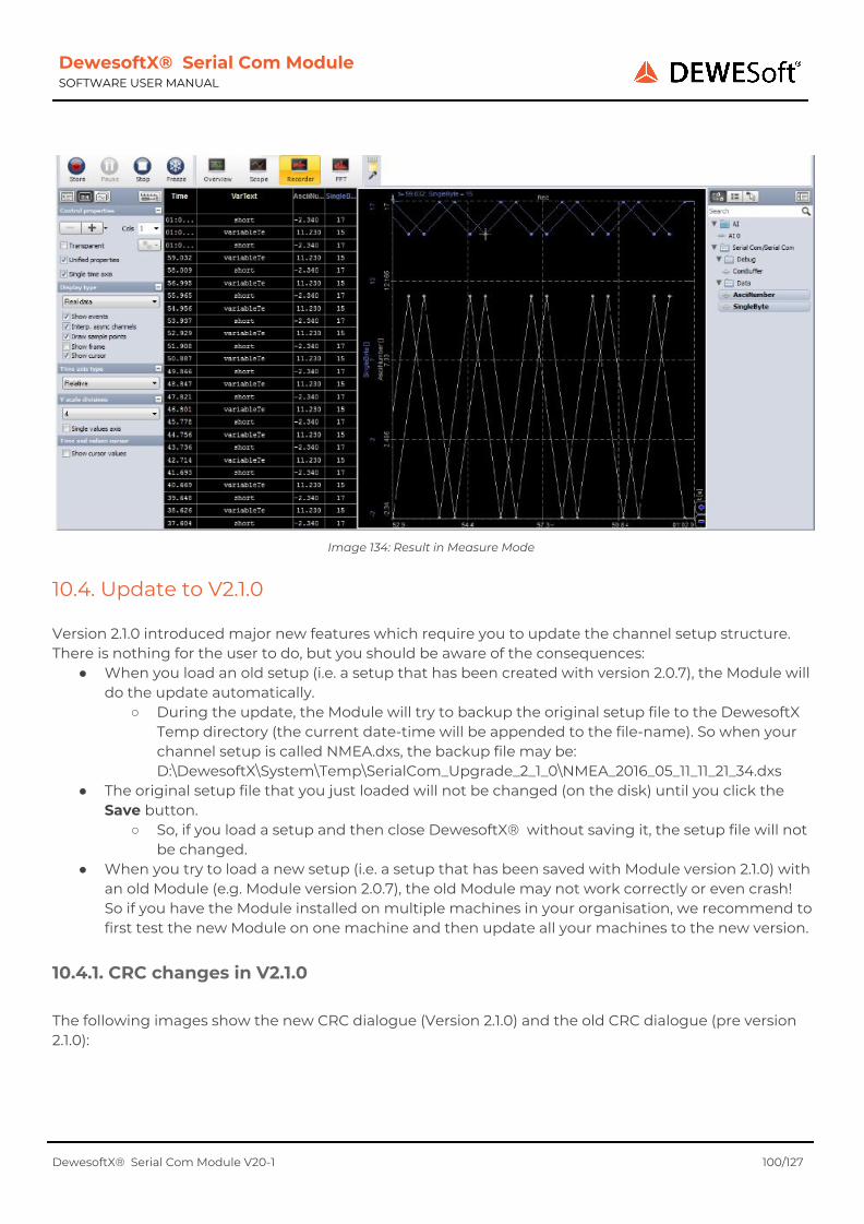
DewesoftX® Serial Com Module SOFTWARE USER MANUAL
Image 134: Result in Measure Mode
10.4. Update to V2.1.0 Version 2.1.0 introduced major new features which require you to update the channel setup structure. There is nothing for the user to do, but you should be aware of the consequences:
● When you load an old setup (i.e. a setup that has been created with version 2.0.7), the Module will do the update automatically.
○ During the update, the Module will try to backup the original setup file to the DewesoftX Temp directory (the current date-time will be appended to the file-name). So when your channel setup is called NMEA.dxs, the backup file may be: D:\DewesoftX\System\Temp\SerialCom_Upgrade_2_1_0\NMEA_2016_05_11_11_21_34.dxs
● The original setup file that you just loaded will not be changed (on the disk) until you click the Save button.
○ So, if you load a setup and then close DewesoftX® without saving it, the setup file will not be changed.
● When you try to load a new setup (i.e. a setup that has been saved with Module version 2.1.0) with an old Module (e.g. Module version 2.0.7), the old Module may not work correctly or even crash! So if you have the Module installed on multiple machines in your organisation, we recommend to first test the new Module on one machine and then update all your machines to the new version.
10.4.1. CRC changes in V2.1.0 The following images show the new CRC dialogue (Version 2.1.0) and the old CRC dialogue (pre version 2.1.0):
DewesoftX® Serial Com Module V20-1 100/127

DewesoftX® Serial Com Module SOFTWARE USER MANUAL
Image 135: CRC 2.1.0
Image 136: CRC pre V2.1.0
Notes:
● The old Include Start String check-box has been moved to the Response dialogue and is now called 'Use for Checksum' (see in Image 135)
● The old NMEA0183 V3 checksum (which is just an XOR8 checksum) can now be activated via the corresponding preset (see chapter Presets) or by selecting XOR 8 directly.
● The old 16bit Sum is now called Sum 16 see also: chapter CRC
DewesoftX® Serial Com Module V20-1 101/127

DewesoftX® Serial Com Module SOFTWARE USER MANUAL
11. Configuration Examples
11.1. NMEA-0183 WIMWV $WIMWV is an NMEA sentence that provides information about wind speed and angle, which will be sent by simple wind sensors via serial port to the PC.
11.1.1. Format The format of the $WIMWV sentence is defined like this: $WIMWV,(1),(2),(3),(4),(5)*hh<CR><LF> Fields:
(1) Wind angle, 0.0 to 359.9 degrees (2) Reference: R = Relative, T = Theoretical (3) Wind speed (4) Wind speed units: K = km/h, M = m/s, N = knots (5) Status: A = data valid; V = data invalid
* is the checksum separator hh is the NMEA-0183 V3 check sum: the data to calculate the checksum is the complete request, except the starting $, the * and the checksum itself.
11.1.2. Configuration Weather stations usually just start to transmit data automatically once they are powered up, so we need not define any requests – just the response definition for the WIMWV sentence. In order to test the response that we create throughout this example, we will use this valid test-data : \$WIMWV,265,R,5.7,M,A*3D
We create a new response and call it Wind Speed And Angle and enter the Startstring ($) of this response (see (1) in Image 137): Note: that the start-string needs to be escaped correctly (\$): see chapter Character escaping. Now we can click the Add button to create the first response part (see (2) in Image 137): we call it ID and set the End Definition to the Stop string WIMWV,. We also activate the Exact match check-box, because between the Startstring ($) and the Stop string (WIMWV,), there must not be any other characters. We keep both check-boxes in the Checksum group active, because the Stop string must be part of the checksum.
Image 137: WIMWV Id
Now we can already enter the test-data and click the Test button: we can see that the Device Data column is still empty – which is okay in this case, because we have selected Ignore response for this response part.
Just to show the difference, we can now enter an error into the Test Response; e.g. we can enter an X between $ and WIMWV, so that our response part definition for the first part does not match anymore: \$XWIMWV,265,R,5.7,M,A*3D After clicking the Test button, the Device Data
DewesoftX® Serial Com Module V20-1 102/127

DewesoftX® Serial Com Module SOFTWARE USER MANUAL
column now shows the error message 'not found' for the first response part: because the Stop string WIMWV, has not been found after the Startstring. Note: if we had not activated the Exact match check-box for the response part, the data would still match (you can try it). Before you continue, make sure to enter the correct Test Response again, for the next steps.
Now we enter the 2nd response part, called Wind Angle. We use the Stop string , and select the Response Part Handler Numeric. The decimal separator must be Dot (according to the NMEA specification). And we can enter Min of 0.0 and Max of 360.0.
It is always a good idea to test the new response part immediately after you create it, to find problems/errors immediately. In our case, the test works fine: we can see in column Device Data, that the characters 265 (highlighted in yellow) of the Test Response were used for the 2nd response part Wind Angle. Since we have chosen the Response Part Handler Numeric with interpretation Ascii, these characters will be converted to the floating point number 256, multiplied with the scale factor (which is 1) and finally the offset is added (which is 0) and so the final result that will show up in the DewesoftX® channel, is 256.
Image 138: Response Part 2: Wind Angle
We call the next response part Reference, and use the Stop string , again. But this time the data
Time for another test. Also this test is okay – we can see that the character R of the Test Response
DewesoftX® Serial Com Module V20-1 103/127

DewesoftX® Serial Com Module SOFTWARE USER MANUAL
is not numeric, but a character, so we select the Response Part Handler Text. Since the data for this part is only a single character, we set the Length to 1.
is used for the request part. Since there is no scaling possible for text data the Converted column shows the same a s the Device Data column.
The next response part Wind Speed is very much like the response part Wind Angle which we have already created. Therefore it is the fastest way to select the existing Wind Speed response part and click the Duplicate button:
Now we just need to change the Name of the duplicated response part to Wind Speed and we change the Min/Max values to Auto (since the documentation does not say what the minimum and maximum values are).
Next is the Wind Speed Unit which is very similar to Reference – so just select Reference, click Duplicate and change the name – done.
Next is the last data field, named Status – since the data is also very similar we can create a duplicate of Reference. But this time there are 2 things to change: 1) the character after the Status is not a ,, but an * instead – so we change the Stop string 2) the * must not be used for the checksum calculation, so we deactivate the use Stop string for checksum check-box
DewesoftX® Serial Com Module V20-1 104/127

DewesoftX® Serial Com Module SOFTWARE USER MANUAL
Now that we have defined all the response parts, we can add the check sum: just click the CRC button and select Preset NMEA-0183 V3:
Finished – time for a test. The test looks already quite good – all the response parts have been found correctly. The only problem is that the Device Data column of the Checksum shows a warning CRC mismatch. In the Converted column, you can see which parts of the Test Response have been used for the checksum calculation: $WIMWV,265,R,5.7,M,A The problem is, that the start string ($) has also been used for the checksum calculation – but it should not be used...
DewesoftX® Serial Com Module V20-1 105/127

DewesoftX® Serial Com Module SOFTWARE USER MANUAL
We can change this by deactivating the Use for Checksum checkbox (1). Now click the Test button again: very good, everything's okay – also the checksum calculation!
11.2. DMU02 Gyro & Eval board In this example we will use the following hardware (by Silicon Sensing®):
● Capacitive Gyro Evaluation System (CG9230) ● DMU02: Six Degrees of Freedom Dynamics Measurement Unit
The DMU02 sensor is connected to the J4 DMU02 CONNECTOR of the Evaluation Board. The Evaluation Board is connected via USB cable to the PC – on the PC we have a virtual COM port with a baud rate of 38.4k. Note: The drivers seems to work fine on 32-bit systems (tested on Windows XP/Prof./32-bit and Windows 7/Ultimate/32-bit, but sometimes causes a crash (blue screen) on 64 bit systems (seen on Windows 7 (64 bit).
11.2.1. Format The data format of the Evaluation Board is very simple (too simple for production use, because it does not include start string/stop string or checksum). To start the continuous data transmission we must transfer the command: $01. To stop it: $FF. The data itself are transmitted as a 2 byte signed integer. The angular rates are transmitted with Big Byte Endianess and the acceleration data are transmitted in Little Byte Endianess.
11.2.2. Configuration
11.2.2.1. Requests We start with the configuration of the requests, which are very simple.
DewesoftX® Serial Com Module V20-1 106/127
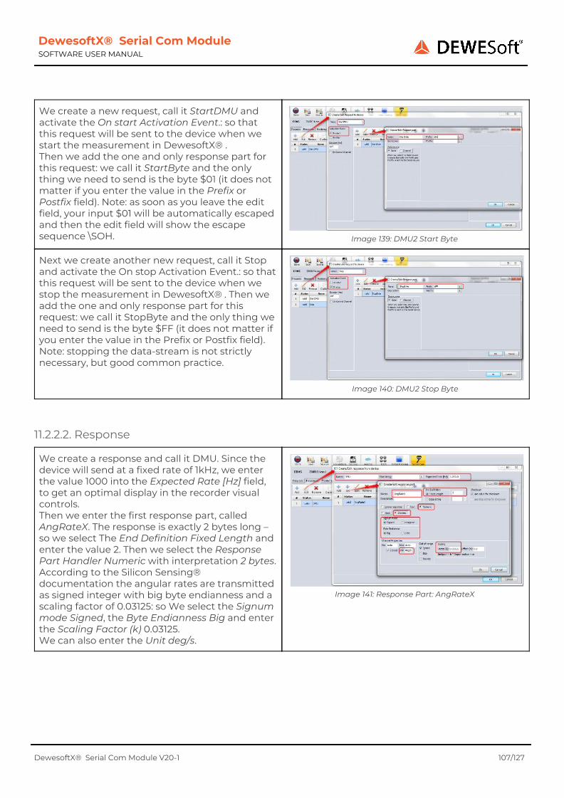
DewesoftX® Serial Com Module SOFTWARE USER MANUAL
We create a new request, call it StartDMU and activate the On start Activation Event.: so that this request will be sent to the device when we start the measurement in DewesoftX® . Then we add the one and only response part for this request: we call it StartByte and the only thing we need to send is the byte $01 (it does not matter if you enter the value in the Prefix or Postfix field). Note: as soon as you leave the edit field, your input $01 will be automatically escaped and then the edit field will show the escape sequence \SOH.
Image 139: DMU2 Start Byte
Next we create another new request, call it Stop and activate the On stop Activation Event.: so that this request will be sent to the device when we stop the measurement in DewesoftX® . Then we add the one and only response part for this request: we call it StopByte and the only thing we need to send is the byte $FF (it does not matter if you enter the value in the Prefix or Postfix field). Note: stopping the data-stream is not strictly necessary, but good common practice.
Image 140: DMU2 Stop Byte
11.2.2.2. Response
We create a response and call it DMU. Since the device will send at a fixed rate of 1kHz, we enter the value 1000 into the Expected Rate [Hz] field, to get an optimal display in the recorder visual controls. Then we enter the first response part, called AngRateX. The response is exactly 2 bytes long – so we select The End Definition Fixed Length and enter the value 2. Then we select the Response Part Handler Numeric with interpretation 2 bytes. According to the Silicon Sensing® documentation the angular rates are transmitted as signed integer with big byte endianness and a scaling factor of 0.03125: so We select the Signum mode Signed, the Byte Endianness Big and enter the Scaling Factor (k) 0.03125. We can also enter the Unit deg/s.
Image 141: Response Part: AngRateX
DewesoftX® Serial Com Module V20-1 107/127

DewesoftX® Serial Com Module SOFTWARE USER MANUAL
Since the data-format specification of the angular rate y is the same as for the angular rate x, we can simply select the response part AngRateX and click Duplicate. The only thing that we must change now is the name of the response part: AngRateY and we are done – all other settings are the same as for the AngRateX. After that we do the same again for AngRateZ and we have already defined all angular rates.
Image 142: Response Part: Duplicate AngRateX
The acceleration data is also quite similar to the angular rates, so we can create a duplicate of e.g. AngRateZ and change the following settings: Name is AccX, the Byte Endianness is now Little, the Unit is g and the Scaling Factor (k) is 0.00366. Since the other acceleration data is the same, we can duplicate AccX twice and change the names of the duplicates to AccY and AccZ respectively.
Image 143: Response Part: Duplicate AngRateZ
Now the response definitions should look like Image 144. We enter some test-data $FF$F0$FF$FE$00\ACK\DC1$00$ED$FF$FE$FE and can see that the final calculated values in the Converted column are correct.
Image 144: Response Test
11.3. EPAD modules In this example we will use the following hardware (by DEWETRON):
● EPAD-TH8-P ● EPAD-V8-P
Note: since the EPAD modules use RS-485 you also need some kind of converter to connect it to the PC and to have a virtual COM port on the PC (e.g. EPAD-BASE module).
11.3.1. Format
DewesoftX® Serial Com Module V20-1 108/127
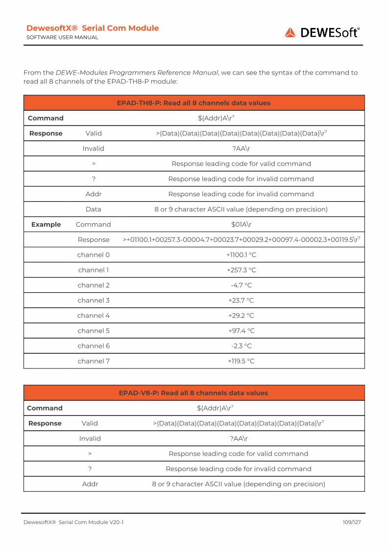
DewesoftX® Serial Com Module SOFTWARE USER MANUAL
From the DEWE-Modules Programmers Reference Manual, we can see the syntax of the command to read all 8 channels of the EPAD-TH8-P module:
EPAD-TH8-P: Read all 8 channels data values
Command $(Addr)A\r7
Response Valid >(Data)(Data)(Data)(Data)(Data)(Data)(Data)(Data)\r7
Invalid ?AA\r
> Response leading code for valid command
? Response leading code for invalid command
Addr Response leading code for invalid command
Data 8 or 9 character ASCII value (depending on precision)
Example Command $01A\r
Response >+01100.1+00257.3-00004.7+00023.7+00029.2+00097.4-00002.3+00119.5\r7
channel 0 +1100.1 °C
channel 1 +257.3 °C
channel 2 -4.7 °C
channel 3 +23.7 °C
channel 4 +29.2 °C
channel 5 +97.4 °C
channel 6 -2.3 °C
channel 7 +119.5 °C
EPAD-V8-P: Read all 8 channels data values
Command $(Addr)A\r7
Response Valid >(Data)(Data)(Data)(Data)(Data)(Data)(Data)(Data)\r7
Invalid ?AA\r
> Response leading code for valid command
? Response leading code for invalid command
Addr 8 or 9 character ASCII value (depending on precision)
DewesoftX® Serial Com Module V20-1 109/127
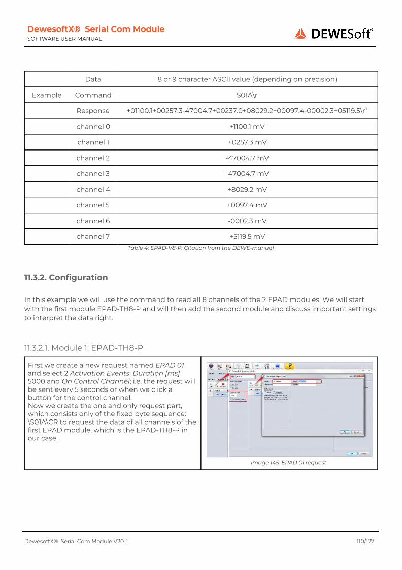
DewesoftX® Serial Com Module SOFTWARE USER MANUAL
Data 8 or 9 character ASCII value (depending on precision)
Example Command $01A\r
Response +01100.1+00257.3-47004.7+00237.0+08029.2+00097.4-00002.3+05119.5\r7
channel 0 +1100.1 mV
channel 1 +0257.3 mV
channel 2 -47004.7 mV
channel 3 -47004.7 mV
channel 4 +8029.2 mV
channel 5 +0097.4 mV
channel 6 -0002.3 mV
channel 7 +5119.5 mV Table 4: EPAD-V8-P: Citation from the DEWE-manual
11.3.2. Configuration In this example we will use the command to read all 8 channels of the 2 EPAD modules. We will start with the first module EPAD-TH8-P and will then add the second module and discuss important settings to interpret the data right.
11.3.2.1. Module 1: EPAD-TH8-P
First we create a new request named EPAD 01 and select 2 Activation Events: Duration [ms] 5000 and On Control Channel; i.e. the request will be sent every 5 seconds or when we click a button for the control channel. Now we create the one and only request part, which consists only of the fixed byte sequence: \$01A\CR to request the data of all channels of the first EPAD module, which is the EPAD-TH8-P in our case.
Image 145: EPAD 01 request
DewesoftX® Serial Com Module V20-1 110/127

DewesoftX® Serial Com Module SOFTWARE USER MANUAL
Now we create the corresponding response. We call it Response EPAD 01. The start string is a > sign. We create the response part for the first temperature channel and call it Ch1. The data that we receive has a fixed size of 8 characters, so we set the End Definition to a Fixed Length of 8.
Image 146: EPAD 01: Ch1
The other 7 channels are easy to create. We simply Duplicate Ch1 and change the names to Ch2, Ch3, etc.
Image 147: EPAD 01: Duplicate Ch1
The channel data is followed by a terminating carriage return character, so we create a final response part named StopChar. The End Definition is of course the Stop string \CR. And we select Ignore response and activate Exact match.
Image 148: EPAD 01: StopChar
Now we can insert the Test Response >+01100.1+00257.3-00004.7+00023.7+00029.2+00097.4-00002.3+00119.5\CR from the DEWE-manual and check the results, which are correct in this case:
DewesoftX® Serial Com Module V20-1 111/127

DewesoftX® Serial Com Module SOFTWARE USER MANUAL
Image 149: EPAD 01: Test Response
Now, let's go to measure mode and check the results. In this example we have added an Input Control Display visual control (Display type to Push Button) and assigned the control channel of the EPAD 01 request: see (1) in Image 150. Right to it, we have a digital display to show all 8 channels of the response. Directly below, we have a Tabular values display to show the Sent requests debug channel (see chapter Sent requests). At the very bottom of the screen there is a recorder showing the data of temperature channel one. At the beginning of the measurement the temperature sensor was just exposed to the room temperature (we see almost no change) and we've never clicked the EPAD 01 button, so that only the timer fired the request every 5 seconds: these data are highlighted by the blue rectangles in Image 150. At the end of the measurement, I've touched the temperature sensor, and clicked the EPAD 01 button several times, so that we can see some changes: see (2) and the red rectangles in Image 150.
DewesoftX® Serial Com Module V20-1 112/127

DewesoftX® Serial Com Module SOFTWARE USER MANUAL
Image 150: EPAD 01: Measurement Data
11.3.2.2. Module 2: EPAD-V8-P The request for the EPAD-V8-P module is almost the same as the request for the response of the EPAD-TH8-P module (except for the module address). Therefore, we can simply Duplicate the response EPAD 01, change the name to EPAD 02 and the Duration [ms] to 1500 and edit the one and only request part AllChannels and change the Prefix to: \$02A\CR (the Prefix of the 1st \$01A\CR). module was:
DewesoftX® Serial Com Module V20-1 113/127
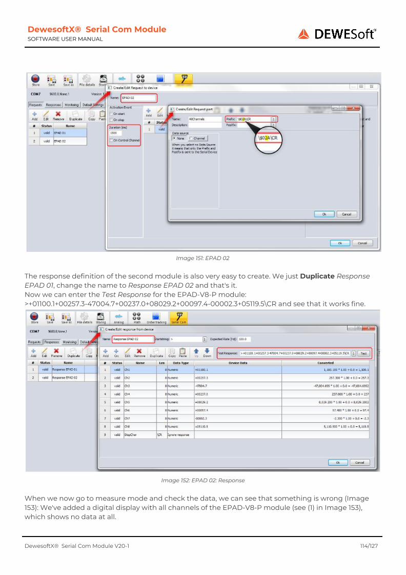
DewesoftX® Serial Com Module SOFTWARE USER MANUAL
Image 151: EPAD 02
The response definition of the second module is also very easy to create. We just Duplicate Response EPAD 01, change the name to Response EPAD 02 and that's it. Now we can enter the Test Response for the EPAD-V8-P module: >+01100.1+00257.3-47004.7+00237.0+08029.2+00097.4-00002.3+05119.5\CR and see that it works fine.
Image 152: EPAD 02: Response
When we now go to measure mode and check the data, we can see that something is wrong (Image 153): We've added a digital display with all channels of the EPAD-V8-P module (see (1) in Image 153), which shows no data at all.
DewesoftX® Serial Com Module V20-1 114/127

DewesoftX® Serial Com Module SOFTWARE USER MANUAL
Also the tabular values display (see (2) in Image 153), shows only data for Ch1 (blue text) one of the Response EPAD 01, but no data for Ch1 (yellowish text) one of the Response EPAD 02. In the recorder (see (3) in Image 153) we can see that the data in Ch1 (blue line) one of the Response EPAD 01 seems unstable. Sometimes it's 0 and every 5 seconds it is about 25. This can already show us the way to the problem: it seems that the data of both modules is written to the same response – always to Response EPAD 01 and never to Response EPAD 02...
Image 153: EPAD 02: Wrong Measurement Data
To prove our suspicion, we can use the Test Response function (see chapter Response Test) in the Responses tab-sheet. We enter the Test Response of Response EPAD 02 into the Response Test, and click the Test button.
Image 154: EPAD: Response test
We can see that both response definitions match the Test Response (which should not be much of a surprise, because Response EPAD 01 is actually a duplicate of Response EPAD 02 - and the format of the responses IS actually the same). In this case it is impossible for the Module to distinguish to which response definition the data belongs. So every response will end up in Response EPAD 01 and none in Response EPAD 02. To solve this problem, we need to give the SerialCom Module more information:
DewesoftX® Serial Com Module V20-1 115/127

DewesoftX® Serial Com Module SOFTWARE USER MANUAL
We change the Response Handling of the request EPAD 01 to Custom and select only Response EPAD 01. As time-out we use 250 ms which is fine for the slow EPAD modules.
We do the same for request EPAD 02, but now we select only Response EPAD 02.
Image 155: EPAD 01: Response Handling
Image 156: EPAD 02: Response Handling
When we now look at the measurement data we can see that everything's fine. The blue line in the recorder shows only the data of the first channel of the EPAD-TH8-P module. The yellowish line in the recorder shows only the data of the first channel of the EPAD-V8-P module (around 0 in this case, because no voltage is connected). This is, because now the SerialCom Module now works like this:
● when it sends the request EPAD 01 it will for response: Response EPAD 01. ● no other request will be sent until the response: Response EPAD 01 is received (or the time-out
occurs). ● when the response: Response EPAD 01 is received (in the specified time-out period), the data will
be written to the channels of Response EPAD 01. The same is true for the 2nd EPAD module. The SerialCom Module will
● send the request EPAD 02 it will for response: Response EPAD 02. ● no other request will be sent until the response: Response EPAD 02 is received (or the time-out
occurs). ● when the response: Response EPAD 02 is received (in the specified time-out period), the data will
be written to the channels of Response EPAD 02.
DewesoftX® Serial Com Module V20-1 116/127

DewesoftX® Serial Com Module SOFTWARE USER MANUAL
Image 157: EPAD: Measurement Data
11.4. Analyt-MTC Massflow meter The Analyt-MTC Massflow meter was connected via ATHEN USB to Serial Bridge to a Windows 7 (64 bit) PC. The baud rate of the device is 19.200 baud (8-N-1 format). The device is configured to send the data automatically after it is powered up.
11.4.1. Format The serial data consists of 5 space-separated fields and a terminating carriage return character: (1) (2) (3) (4) (5)\CR Fields:
(1) absolute pressure (2) temperature (3) volumetric flow rate (4) mass flow (5) text field showing the unit (e.g. AIR)
DewesoftX® Serial Com Module V20-1 117/127

DewesoftX® Serial Com Module SOFTWARE USER MANUAL
11.4.2. Configuration This format is quite easy to set up: We create one response with 1 field for each of the data fields:
We create a single response and add the first part: we call it pressure and use the Numeric handler (with Ascii interpretation). The Stop string is a space character. Then we Duplicate this part 3 times and call the parts temperature, flow rate and mass flow respectively.
The last part is a little different. We call it LastPart, the Stop string is a carriage return character in this case and we select the Text handler.
Image 158: Analyt-MTC: Response Definition
Image 159: Analyt-MTC: Last Part
That's it – we can already test the definition with this Test Response: +938\SPC+025.64\SPC+005\SPC+005\SPC\SPC\SPC\SPC\SPCAir\CR Then click Test and check the results:
When we go to measurement, we can already see the data in the recorder and digital displays.
Image 160: Analyt-MTC: Test
Image 161: Analyt-MTC: Measurement
DewesoftX® Serial Com Module V20-1 118/127

DewesoftX® Serial Com Module SOFTWARE USER MANUAL
12. Warranty information Notice The information contained in this document is subject to change without notice. Note: Dewesoft d.o.o. shall not be liable for any errors contained in this document. Dewesoft MAKES NO WARRANTIES OF ANY KIND WITH REGARD TO THIS DOCUMENT, WHETHER EXPRESS OR IMPLIED. DEWESOFT SPECIFICALLY DISCLAIMS THE IMPLIED WARRANTIES OF MERCHANTABILITY AND FITNESS FOR A PARTICULAR PURPOSE. Dewesoft shall not be liable for any direct, indirect, special, incidental, or consequential damages, whether based on contract, tort, or any other legal theory, in connection with the furnishing of this document or the use of the information in this document. The copy of the specific warranty terms applicable to your Dewesoft product and replacement parts can be obtained from your local sales and service office. To find a local dealer for your country, please visit https://dewesoft.com/support/distributors. 12.1. Calibration Every instrument needs to be calibrated at regular intervals. The standard norm across nearly every industry is annual calibration. Before your Dewesoft data acquisition system is delivered, it is calibrated. Detailed calibration reports for your Dewesoft system can be requested. We retain them for at least one year, after system delivery. 12.2. Support Dewesoft has a team of people ready to assist you if you have any questions or any technical difficulties regarding the system. For any support please contact your local distributor first or Dewesoft directly. Dewesoft d.o.o. Gabrsko 11a 1420 Trbovlje Slovenia Europe Tel.: +386 356 25 300 Web: http://www.dewesoft.com Email: [email protected] The telephone hotline is available Monday to Friday from 07:00 to 16:00 CET (GMT +1:00)
12.3. Service/repair The team of Dewesoft also performs any kinds of repairs to your system to assure a safe and proper operation in the future. For information regarding service and repairs please contact your local distributor first or Dewesoft directly on https://dewesoft.com/support/rma-service.
12.4. Restricted Rights Use Slovenian law for duplication or disclosure. Dewesoft d.o.o. Gabrsko 11a, 1420 Trbovlje, Slovenia / Europe.
DewesoftX® Serial Com Module V20-1 119/127

DewesoftX® Serial Com Module SOFTWARE USER MANUAL
12.5. Printing History Version 2.0.0, Revision 217 Released 2015 Last changed: 23. July 2018 at 16:54. 12.6. Copyright Copyright © 2015-2019 Dewesoft d.o.o. This document contains information which is protected by copyright. All rights are reserved. Reproduction, adaptation, or translation without prior written permission is prohibited, except as allowed under the copyright laws. All trademarks and registered trademarks are acknowledged to be the property of their owners. 12.7. Trademarks We take pride in our products and we take care that all key products and technologies are registered as trademarks all over the world. The Dewesoft name is a registered trademark. Product families (KRYPTON, SIRIUS, DSI, DS-NET) and technologies (DualCoreADC, SuperCounter, GrandView) are registered trademarks as well. When used as the logo or as part of any graphic material, the registered trademark sign is used as a part of the logo. When used in text representing the company, product or technology name, the ® sign is not used. The Dewesoft triangle logo is a registered trademark but the ® sign is not used in the visual representation of the triangle logo.
DewesoftX® Serial Com Module V20-1 120/127

DewesoftX® Serial Com Module SOFTWARE USER MANUAL
13. Safety instructions Your safety is our primary concern! Please be safe! 13.1. Safety symbols in the manual
Warning Calls attention to a procedure, practice, or condition that could cause the body injury or death Caution Calls attention to a procedure, practice, or condition that could possibly cause damage to equipment or permanent loss of data.
13.2. General Safety Instructions
Warning
The following general safety precautions must be observed during all phases of operation, service, and repair of this product. Failure to comply with these precautions or with specific warnings elsewhere in this manual violates safety standards of design, manufacture, and intended use of the product. Dewesoft GmbH assumes no liability for the customer’s failure to comply with these requirements. All accessories shown in this document are available as an option and will not be shipped as standard parts.
13.2.1. Environmental Considerations Information about the environmental impact of the product.
13.2.2. Product End-of-Life Handling Observe the following guidelines when recycling a Dewesoft system:
13.2.3. System and Components Recycling Production of these components required the extraction and use of natural resources. The substances contained in the system could be harmful to your health and to the environment if the system is improperly handled at its end of life! Please recycle this product in an appropriate way to avoid unnecessary pollution of the environment and to keep natural resources.
This symbol indicates that this system complies with the European Union’s requirements according to Directive 2002/96/EC on waste electrical and electronic equipment (WEEE). Please find further information about recycling on the Dewesoft web site www.dewesoft.com Restriction of Hazardous Substances
DewesoftX® Serial Com Module V20-1 121/127

DewesoftX® Serial Com Module SOFTWARE USER MANUAL
This product has been classified as Monitoring and Control equipment and is outside the scope of the 2002/95/EC RoHS Directive. However, we take care of our environment and the product is lead-free.
13.2.4. General safety and hazard warnings for all Dewesoft systems Safety of the operator and the unit depend on following these rules.
● Use this system under the terms of the specifications only to avoid any possible danger. ● Read your manual before operating the system. ● Observe local laws when using the instrument. ● DO NOT touch internal wiring! ● DO NOT use higher supply voltage than specified! ● Use only original plugs and cables for harnessing. ● You may not connect higher voltages than rated to any connectors. ● The power cable and connector serve as Power-Breaker. The cable must not exceed 3 meters,
the disconnect function must be possible without tools. ● Maintenance must be executed by qualified staff only. ● During the use of the system, it might be possible to access other parts of a more comprehensive
system. Please read and follow the safety instructions provided in the manuals of all other components regarding warning and security advice for using the system.
● With this product, only use the power cable delivered or defined for the host country. ● DO NOT connect or disconnect sensors, probes or test leads, as these parts are connected to a
voltage supply unit. ● Ground the equipment: For Safety Class 1 equipment (equipment having a protective earth
terminal), a non-interruptible safety earth ground must be provided from the mains power source to the product input wiring terminals.
● Please note the characteristics and indicators on the system to avoid fire or electric shocks. Before connecting the system, please read the corresponding specifications in the product manual carefully.
● The inputs must not, unless otherwise noted (CATx identification), be connected to the main circuit of category II, III and IV.
● The power cord separates the system from the power supply. Do not block the power cord, since it has to be accessible for the users.
● DO NOT use the system if equipment covers or shields are removed. ● If you assume the system is damaged, get it examined by authorized personnel only. ● Adverse environmental conditions are Moisture or high humidity Dust, flammable gases, fumes
or dissolver Thunderstorm or thunderstorm conditions (except assembly PNA) Electrostatic fields, etc.
● The measurement category can be adjusted depending on module configuration. ● Any other use than described above may damage your system and is attended with dangers like
short-circuiting, fire or electric shocks. ● The whole system must not be changed, rebuilt or opened. ● DO NOT operate damaged equipment: Whenever it is possible that the safety protection
features built into this product have been impaired, either through physical damage, excessive moisture, or any other reason, REMOVE POWER and do not use the product until the safe operation can be verified by service-trained personnel. If necessary, return the product to Dewesoft sales and service office for service and repair to ensure that safety features are maintained.
● If you assume a more riskless use is not provided anymore, the system has to be rendered inoperative and should be protected against inadvertent operation. It is assumed that a more
DewesoftX® Serial Com Module V20-1 122/127

DewesoftX® Serial Com Module SOFTWARE USER MANUAL
riskless operation is not possible anymore if the system is damaged obviously or causes strange noises. The system does not work anymore. The system has been exposed to long storage in adverse environments. The system has been exposed to heavy shipment strain.
● Warranty void if damages caused by disregarding this manual. For consequential damages, NO liability will be assumed!
● Warranty void if damage to property or persons caused by improper use or disregarding the safety instructions.
● Unauthorized changing or rebuilding the system is prohibited due to safety and permission reasons (CE).
● Be careful with voltages >25 VAC or >35 VDC! These voltages are already high enough in order to get a perilous electric shock by touching the wiring.
● The product heats during operation. Make sure there is adequate ventilation. Ventilation slots must not be covered!
● Only fuses of the specified type and nominal current may be used. The use of patched fuses is prohibited.
● Prevent using metal bare wires! Risk of short circuit and fire hazard! ● DO NOT use the system before, during or shortly after a thunderstorm (risk of lightning and high
energy over-voltage). An advanced range of application under certain conditions is allowed with therefore designed products only. For details please refer to the specifications.
● Make sure that your hands, shoes, clothes, the floor, the system or measuring leads, integrated circuits and so on, are dry.
● DO NOT use the system in rooms with flammable gases, fumes or dust or in adverse environmental conditions.
● Avoid operation in the immediate vicinity of high magnetic or electromagnetic fields, transmitting antennas or high-frequency generators, for exact values please refer to enclosed specifications.
● Use measurement leads or measurement accessories aligned with the specification of the system only. Fire hazard in case of overload!
● Do not switch on the system after transporting it from a cold into a warm room and vice versa. The thereby created condensation may damage your system. Acclimatise the system unpowered to room temperature.
● Do not disassemble the system! There is a high risk of getting a perilous electric shock. Capacitors still might be charged, even if the system has been removed from the power supply.
● The electrical installations and equipment in industrial facilities must be observed by the security regulations and insurance institutions.
● The use of the measuring system in schools and other training facilities must be observed by skilled personnel.
● The measuring systems are not designed for use in humans and animals. ● Please contact a professional if you have doubts about the method of operation, safety or the
connection of the system. ● Please be careful with the product. Shocks, hits and dropping it from already- lower level may
damage your system. ● Please also consider the detailed technical reference manual as well as the security advice of the
connected systems. ● This product has left the factory in safety-related flawlessness and in proper condition. In order to
maintain this condition and guarantee safety use, the user has to consider the security advice and warnings in this manual.
EN 61326-3-1:2008
DewesoftX® Serial Com Module V20-1 123/127
DewesoftX® Serial Com Module SOFTWARE USER MANUAL
IEC 61326-1 applies to this part of IEC 61326 but is limited to systems and equipment for industrial applications intended to perform safety functions as defined in IEC 61508 with SIL 1-3. The electromagnetic environments encompassed by this product family standard are industrial, both indoor and outdoor, as described for industrial locations in IEC 61000-6-2 or defined in 3.7 of IEC 61326-1. Equipment and systems intended for use in other electromagnetic environments, for example, in the process industry or in environments with potentially explosive atmospheres, are excluded from the scope of this product family standard, IEC 61326-3-1. Devices and systems according to IEC 61508 or IEC 61511 which are considered as “operationally well-tried”, are excluded from the scope of IEC 61326-3-1. Fire-alarm and safety-alarm systems, intended for the protection of buildings, are excluded from the scope of IEC 61326-3-1.
DewesoftX® Serial Com Module V20-1 124/127

DewesoftX® Serial Com Module SOFTWARE USER MANUAL
14. Documentation version history
Version Date Notes
2.0.0 14.12.2012 ☑Now multiple serial devices are supported by the Module □ Each device has it's own logfile ☑Major changes to the parsing logic □ better performance □ improved GUI responsiveness in Measure mode (parsing is done in a separate thread/s) ☑BinHex Encoding is now supported ☑Request Parts now support 4 byte numeric data ☑ Monitoring: added skipped data channel ☑Major changes to Control Centre □ the Control Centre can now also be used in channel setup □ sending of the predefined requests in channel setup is possible □ grouping mode responses is supported in channel setup □ better parsing performance + added progress indication □ improved GUI responsiveness (parsing is done in a separate thread) □ improved performance when saving a big xml file □ added Auto Scroll check-box □ settings for encoding an grouping will be saved in channel setup ☑ Input fields: added indication for unsaved changes (yellow colour) Documentation changes: ☑Major changes to Control Centre chapter ☑Chapter Monitoring is now one level higher (was sub-chapter of Responses before) ☑ TOC: entries are now hyper-links, showing less heading levels
2.0.1 25.02.2013 ☑Numeric Data Ascii Interpretation: ASCII: space and tab characters after the signum are ignored Documentation changes: ☑ 7.3.1.4.1 Numeric Data Ascii Interpretation: ASCII: space and tab characters after the signum are ignored ☑ now all TOC entries are hyper links (was only for top-level chapters before)
2.0.2 22.03.2013 ☑Added Flow Control settings ☑ Fixed problem with COM port selection when opening the Control Centre from Hardware setup ☑ LongTest resources (for internal startup tests) are now compiled into the dll (instead of using a fixed path to the file location) Documentation changes: ☑Added Flow Control settings
DewesoftX® Serial Com Module V20-1 125/127

DewesoftX® Serial Com Module SOFTWARE USER MANUAL
2.0.3 04.11.2013 ☑Added feature to send acknowledge to responses ☑Now the Scale factor can have more than only 2 decimal places ☑ Fixed possible Access Violation when using the Custom Response Handling ☑ Fixed issue with handling of the modal windows of the Module ☑ Fixed possible issue with dangling DewesoftX® channel references (introduced new IHasIChannelRefs interface) Documentation changes: ☑Added chapter 7.2.2 Receive Action ☑Updated to Open Office 4.0.1 (removed frames around images)
2.0.4 02.04.2015 ☑ Improved error handling in HW-setup ☑Added Data-Wait [ms] in HW-setup ☑Max. Timeout for Requests is now 10s ☑New Module logo is a png for transparency Documentation changes: ☑Updated to X2 (installation, registration) and to the new orange design
2.0.5 28.05.2015 ☑ Fixed a problem with negative scale factors (the user-input field doubled the negative signum and then reported an error)
2.0.6 13.07.2015 ☑ Improved timestamps when the CPU load is very high and you start storing directly from Ch. Setup
2.0.7 06.08.2015 ☑DewesoftX® X2 input channels can now be used in Requests ☑ Fixed possible problem with Status Channel ☑Better error-handling when sending requests (old version showed pop-ups)
2.1.0 11.05.2016 ☑Major improvements to CRC handling: new XML setup version: see chapter1 CRC changes in V2.1.0 ☑ Fixed problem with Store checkbox of the Response parts. Documentation changes: ☑ chapter 6 Requests: □Updated some screenshots □Rearranged some chapters □Added 6.3.2.2 User for Crc □Added Request Part Crc ☑Updated Response CRC chapter ☑Updated some screenshots in chapter “10.1 NEMA-0183 WIMWV” ☑Added Chapter “Update to V2.1.0” ☑History: Merged the Module and Documentation, removed old entries (before version 2)
2.1.1 24.10.2017 ☑ The Module now supports arbitrary baud rates □ This also required a change in the
DewesoftX® Serial Com Module V20-1 126/127
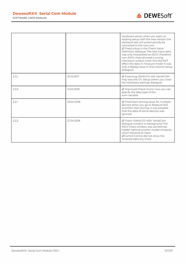
DewesoftX® Serial Com Module SOFTWARE USER MANUAL
Hardware setup: when you open an existing setup with the new version the old baud rate will automatically be converted to the new one ☑ Fixed a bug in the Check Value Definition dialogue: The test-input data was only interpreted as ASCII: therefore non-ASCII chars showed a wrong checksum output (note: this did NOT affect the data in measure mode: it was only a display issue in this channel setup dialogue)
2.1.2 20.12.2017 ☑ Fixed bug SWAUTO-455: SerialCOM may lose the Ch. Setup (when you close the Hardware settings dialogue)
2.2.0 14.02.2018 ☑ Improved Check-Sums: now you can specify the data type of the sum-variable.
2.2.1 05.04.2018 ☑ Fixed start-storing issue: for multiple devices when you go to Measure first and then start storing, it was possible that the data of some devices was ignored
2.2.2 27.04.2018 ☑ Fixed <SWAUTO-450> SerialCom dialogue window in background The ASCII Chars window was sometimes hidden behind another modal windows which blocked all input ☑Control Centre did not show the received data any more
DewesoftX® Serial Com Module V20-1 127/127