device drivers cpu i/o interface device driver devicecontrol operationsdata transfer operations disk...
TRANSCRIPT

Device Drivers

CPU
I/O
InterfaceDevice
Device
Driver

DEVICE CONTROL OPERATIONS DATA TRANSFER OPERATIONS
DiskSeek to Sector, Track, Cyl.Seek Home Position
Read SectorWrite Sector
Magnetic Tape
RewindForward Space RecordBackspace RecordWrite Mark
Read RecordWrite RecordRead Backwards
Printer **Print characterLoad fontInitialize
Terminal **Read CharacterWrite Character
Mouse Read positionRead button status
** Control operations are normally invoked by special characters in the data streamFigure 9--1: I/O Operations for Typical Devices


Memory mapped I/O

Figure 10--3: I/O Subsystem as an Integral Part of the OS

Figure 10--4: Device Drivers as Separate Modules

Implementation strategies for handling devices
• Programmed I/O
• Block transfer
• I/O processors

Simple Polling algorithm/* initialize pointer and index */
ix=0;count = BUFLEN;
/* begin polling loop */while ((count > 0) && (no device error)) {
/* wait while device is busy */while (device is busy) {}
/* process character if no error */if (no device error) {
write buffer[ix]; /* write next character */count = count - 1; /* decrement count */ix = ix + 1; /* increment index */
}}

Polling using Memory mapped i/o• /* initialize pointer and index */• ix=0;• count = BUFLEN;• /* begin polling loop */• while ((count < 0) && (error bit of status register is 0)) {• • /* wait while device is busy */• while (status bit of status register is BUSY) {}• /* process character if no error */• if (error bit of status register is 0) {• data register = buffer[ix]; /* write next character */• count = count - 1; /* decrement count */• ix = ix + 1; /* increment index */• }• }

• Using interrupts for device management:– Starting I/O– Returning to the process or OS– Device generates an interrupt signal

InterruptsMAIN PROGRAM:/* initialize index, count, and device flag */ix = 0;count = BUFLEN;dev_flag = 0;...enable interrupts for device.../* loop until all characters are written */while (dev_flag == 0) {}...INTERRUPT HANDLER:save registers/* check for errors */if (error) {dev_flag = -1; /* set flag to error code */disable interrupts for devicerestore registersreturn from interrupt}
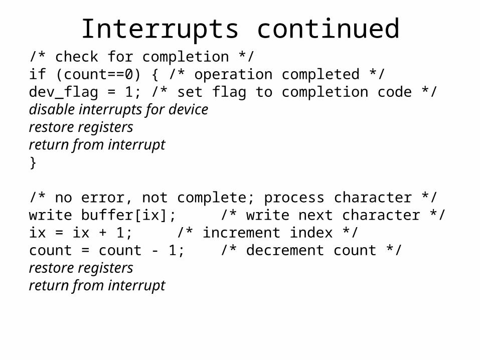
Interrupts continued/* check for completion */if (count==0) { /* operation completed */dev_flag = 1; /* set flag to completion code */disable interrupts for devicerestore registersreturn from interrupt}
/* no error, not complete; process character */write buffer[ix]; /* write next character */ix = ix + 1; /* increment index */count = count - 1; /* decrement count */restore registersreturn from interrupt

Buffering
• Buffering is a technique that can be used to improve device as well as CPU throughput
• Buffering is the use of temporary storage areas in memory to store data that is read from an input device before it is needed. Process can also use buffering to store data before it is sent to the output device

Buffering with character devices

Ring Buffer
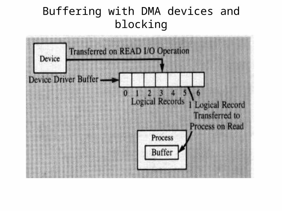
Buffering with DMA devices and blocking

BUFFER1
BUFFER2
DISK1
CPU/PROCESS
READ MORE DATA
PROCESS
Device
Driver

BUFFER1
BUFFER2
CPU/PROCESS
Read Last logical record from buffer 1
DISK1
Start read from device to fill buffer 2

Copying with a single buffer WHILE NOT END_OF_FILE(TAPE1)
READ TAPE1,BUFFER
WAIT TAPE1
IF NOT END_OF_FILE(TAPE1)
WRITE TAPE2,BUFFER
WAIT TAPE2
ENDIF
ENDWHILE

Copying with double buffers READ TAPE1,BUFFER1 WHILE NOT END_OF_FILE(TAPE1) WAIT TAPE1 WAIT TAPE2 IF NOT END_OF_FILE(TAPE1) READ TAPE1,BUFFER2 WRITE TAPE2,BUFFER1 ENDIF WAIT TAPE1 WAIT TAPE2 IF NOT END_OF_FILE(TAPE1) READ TAPE1,BUFFER1 WRITE TAPE2,BUFFER2 ENDIF ENDWHILE

Software Caching

Data structures for Device Management
• I/O operations that are in progress need to be represented by some type of data structure in every operating system
• This data structure can be called by various names DCB, IOB, IOCB
• It represents a device, channel or controller, and the activity of the device

Data structures for device management: I/OCB
Channel (port ) Number Controller AddressDevice NameDevice AddressInterrupt Vector AddressAddress of Interrupt HandlerDevice TypeAddress of Open ProcedureAddress of Close ProcedureAddress of Start I/O ProcedureAddress of Cancel I/O ProcedureBuffer AddressBuffer LengthCurrent Buffer PointerCurrent Data CountCurrent I/O OperationAddress of PCB of Process which requested the OperationAddress of I/O Request ParametersAddress of ECB for Current OperationFigure 10--15: Information Stored in an I/O Control Block
Device table entry
• Device Name• Device Status• Device Driver File Name or Disk Address• Entry Point in Main Memory, if loaded• Device Size• Device Driver Size• Logical Name(s)
• Figure 10--16: Content of a Typical Device Table Entry

Device driver organization: structure and functions of device drivers
Figure 10--17: Structure and Functions of Device Drivers
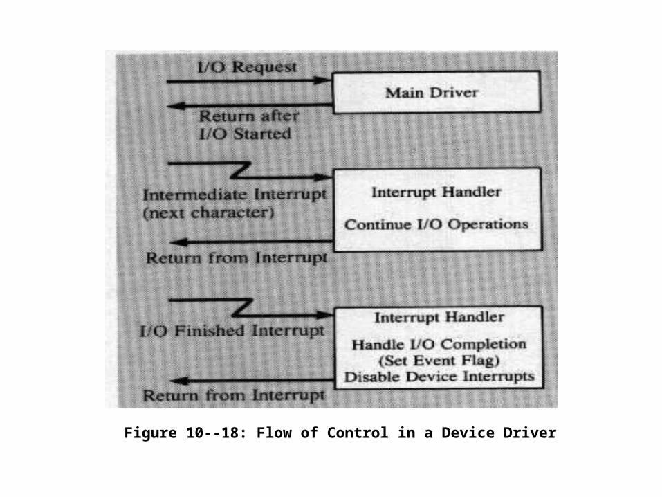
Figure 10--18: Flow of Control in a Device Driver

Preparing for I/O
• Preparation for I/O is the first activity of a device driver when invoked via one of the device system calls.
• I/O system call parameters must:– specify the type of operation requested (read, write, control), – the address of the data buffer to be used, – the size of the data area, – and other relevant information. – Additionally, device-dependent parameters, such as track and sector numbers for disk operations, may also
be required.• Preparation of I/O components of a device driver validates device-specific parameters of an I/O
request. Appropriate error return codes must be provided to the user for any errors detected in the service request parameters.
• The preparation for I/O might include:– temporary buffer allocation or initialization, – formatting of data, – placing information in the appropriate location(s) in some I/O control block that is accessible to the device
interrupt handler and the operating system. • Once the I/O request parameters are validated, the device status must be checked. If the device
is busy or not ready, the device driver must take an appropriate system dependent action. – If an error condition or problem such as "device not ready" is detected, the driver might take action causing
the application process to terminate, or it might simply provide a return code to be passed back to the process, which then must deal with the problem in a suitable way depending on the application.
– In a multiprogramming operating system, the response may include queuing the I/O request for a shared device that is presently busy with another operation.
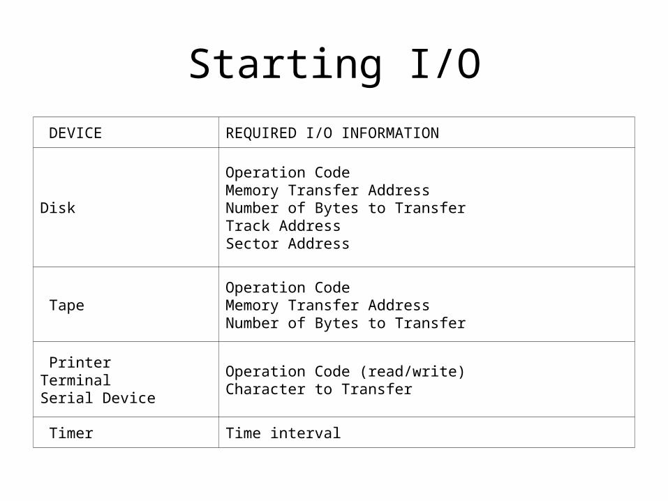
Starting I/O
DEVICE REQUIRED I/O INFORMATION
Disk
Operation CodeMemory Transfer AddressNumber of Bytes to TransferTrack AddressSector Address
TapeOperation CodeMemory Transfer AddressNumber of Bytes to Transfer
PrinterTerminalSerial Device
Operation Code (read/write)Character to Transfer
Timer Time interval

Interrupt Servicing• The most complicated part of most I/O drivers or I/O supervisor modules is
the interrupt handler. • Much of the device control is embedded in the interrupt handler, which is
given control asynchronously when the device needs service. – This could involve processing the next character for a device in the case of a
non-DMA device, – starting a second or third phase of an I/O operation for DMA devices (for
example, a read after a seek to sector on some disks).• Information needed by the interrupt handler must be provided by the main
portion of the device driver. Such information is usually contained in the I/O control blocks that represent the current I/O operation, just as PCBs represent process execution to the dispatcher.
– Device interrupt handlers must save all registers and hardware status of the interrupted program. In a stack machine, this merely involves saving information on the stack and restoring it before returning to the interrupted program.
– Certainly the most complex part of interrupt handler service is error recovery – Error recovery routines can be either resident or dynamically loaded when
needed, depending on operating system design and requirements.

Possible errors for devices
DEVICE POSSIBLE ERRORS
Disk
Invalid Track, SectorWrong DensityPower UnsafeData error
TapeData errorEnd of tape
PrinterPaper outPaper jamOff Line

Sample Error HandlerERROR HANDLER:
/* initialize counter and flag */loop = 0;tape_error = TRUE;/* repeat entire process up to ten times */while ((loop < 10) && tape_error) {/* backspace and reread up to nine times */count = 0;while ((count < 9) && tape_error) {backspace recordread record againif (read is ok) tape_error = FALSE;else count = count + 1;}

/* if error still present, backup further */if (tape_error) {
/* backspace ten records */count = 0;while (count < 10) {backspace recordcount = count + 1;
}/* skip forward nine records */count = 0;while (count < 9) {
forward space recordcount = count + 1;
}/* try reading again */read recordif (read is ok) tape_error = FALSE;loop = loop + 1; /* prepare for retry */} /* repeat if necessary */

Device Driver Components and Responsibilities
• I/O System Call Interface– Mechanism to invoke device driver– Format of parameter list– Locating parameter list
• Preparation for I/O– Validate parameters– Save parameters in I/O control block– Pass error codes to process or to OS– Place in I/O queue or invoke start component
• Starting of I/O– Enable Interrupts– Issue first I/O command to device– Return to calling process or to OS

• Interrupt Servicing– Save registers– Determine cause of interrupt– If error, invoke error recovery routine– If operation not done, issue next I/O command– advance pointer(s)– decrement count(s)– restore registers– return from interrupt– If operation complete, set event flag– invoke completion routine
• Error Detection and Recovery– Invoke error recovery algorithm– If error recovers, resume interrupt handler– If error is permanent, set event flag to error code and– invoke completion routine
• Completion of I/O (Return to Idle)– Set event flag– Disable interrupts– Move process just finished with device to ReadyQ– Invoke I/O scheduler– Invoke dispatcher
• Cancellation of I/O– If I/O request in I/O queue, remove it– Return to caller

Scheduling I/O
process1 process2 process3
I/O event 1
I/O event 3
I/O event 2
Device or I/O queue

Multiple I/O queues
Figure 10--23: A Single I/O Queue
Figure 10--24: Multiple I/O Queues

PCB 0
Priority 60
Running Process
Ready QIO_Active Q
IO_Init Q
PCB 9
Priority 32
PCB 8
Priority 40
PCB 5
Disk Read
PCB 4
Printer Write
PCB 3
Disk Write
PCB 2
Disk Read
PCB1
Printer Write
PRINTER_IOCB
PCB7 Address
ECB Address
DISK_IOCB
PCB6 Address
ECB Address
Modified figure 10-25
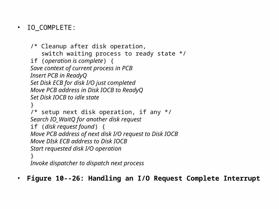
• IO_COMPLETE:
/* Cleanup after disk operation, switch waiting process to ready state */if (operation is complete) {Save context of current process in PCBInsert PCB in ReadyQSet Disk ECB for disk I/O just completedMove PCB address in Disk IOCB to ReadyQSet Disk IOCB to idle state}/* setup next disk operation, if any */Search IO_WaitQ for another disk requestif (disk request found) {Move PCB address of next disk I/O request to Disk IOCBMove DIsk ECB address to Disk IOCBStart requested disk I/O operation}Invoke dispatcher to dispatch next process
• Figure 10--26: Handling an I/O Request Complete Interrupt

Running Process
Ready QIO_Active Q
IO_Init Q
PCB 8
Priority 40
PCB 6
Priority 42
PCB 5
Disk Read
PCB 4
Printer Write
PCB 3
Disk Write
PCB1
Printer Write
PRINTER_IOCB
PCB7 Address
ECB Address
DISK_IOCB
PCB2 Address
ECB Address
PCB 0
Priority 60
PCB 9
Priority32
Modified Figure 1--27

Figure 10--28: State Transitions with IO_init and IO_active States