development of ultra-high-speed elevator that achieved … · 220 development of ultra-high-speed...
TRANSCRIPT

Hitachi Review Vol. 66 (2017), No. 3 219
- 45 -
Featured Articles II
at the time) and used to develop and test features
such as accurate speed control technology, vibration
noise control technology, and high-speed safety
equipment, culminating in the successful completion
of the 300-m/min ultra-high-speed elevator(1). This was
followed in 1974 by the development of a 540-m/min
ultra-high-speed elevator for the Shinjuku Sumitomo
Building. In 1993, Hitachi developed technology for
an 810-m/min elevator (the world’s fastest at that time)
in response to the trend toward buildings of 100 stories
or more(2).
With the start of the new century, meanwhile,
elevator manufacturers around the world were
participating in the major new market that had
emerged from the rapid economic growth taking place
in Asia, particularly in the Chinese market. The trend
in the Middle East, too, was toward taller and larger
buildings, creating a demand for ultra-high-speed and
high-capacity elevators.
An elevator with a speed of 1,010 m/min commenced
operation in Taiwan in 2004, making it the world’s
fastest(3). Hitachi, meanwhile, has continued to build
up its own technical capabilities for elevators with
high capacity and long travel, including construction
techniques, with the development of high-capacity
elevators for the Shanghai World Financial Center with
a travel distance of approximately 440 m in 2008(4).
In 2010, Hitachi constructed a new elevator research
tower with the world’s highest above-ground height
INTRODUCTION
NUMEROUS skyscrapers exceeding a height of
500 m are being planned in China and Middle
Eastern countries. A strong brand and a technological
presence indicative of high reliability are prerequisites
for maintaining competitiveness in this market. To
strengthen its competitiveness and to expand its share
of the market for skyscrapers, Hitachi developed a
1,200-m/min elevator for the Guangzhou Chow Tai
Fook (CTF) Finance Centre.
Hitachi equipped the new elevator with drive
and control systems that achieve the world’s fastest
speed, a governor and brake that stop the elevator car
in an emergency, and new technologies that prevent
lateral vibration of the car caused by guide rail joints
or warping and reduce the sensation of ear blockage
caused by pressure differences. New techniques for
constructing and fastening the guide rails were also
adopted for use during on-site installation.
This article describes the new technologies developed
in order to achieve these 1,200-m/min elevators.
DEVELOPMENT BACKGROUND
Hitachi’s development of skyscraper elevators began
in 1968 with the delivery of 300-m/min elevators
for the Kasumigaseki Building. A 90-m elevator
research tower was constructed (the world’s highest
OVERVIEW: A strong brand and a technological presence indicative of high reliability are prerequisites for maintaining competitiveness in the market for landmark skyscrapers, many of which are being planned in China and Middle Eastern countries. Developing the world’s fastest elevators has been among Hitachi’s objectives since it built its new elevator research tower. As a result of its ongoing work on element technology development and verifi cation testing, Hitachi received an order to manufacture 1,200-m/min elevators for the Guangzhou CTF Finance Centre. This development included creating a heavy-duty drive system, highly reliable safety systems, elevator cars that provide users with a comfortable ride, and establishing construction techniques. A speed of 1,200 m/min was verifi ed in May 2016, achieving the fastest speed for elevators that currently exist in the world (as of May 2016, as determined by Hitachi).
Hideka Matsuoka
Yoshiki Higashida
Naoto Ohnuma
Takashi Abe
Tetsuya Nakayama
Yosuke Kawamura
Yue Zheng Guan
Keizo Nakamura
Chen Song Xin
Xie Yi Xin
Atsushi Arakawa, Dr. Eng.
Development of Ultra-High-Speed Elevator that Achieved the World’s Fastest Elevator with a Speed of 1,200 m/min

220 Development of Ultra-High-Speed Elevator that Achieved the World’s Fastest Elevator with a Speed of 1,200 m/min
- 46 -
of 213 m at that time. Hitachi has used the tower as
a research facility for developing and supplying the
world’s fastest elevators, and has conducted various
trials and developed technologies that take account of
safety, comfort, and the environment(5) (see Fig. 1).
DEVELOPMENT WORK AND FEATURES
Faster elevators not only make skyscrapers more
convenient by transporting users to the destination
fl oor more quickly, they also enhance the value of
the building itself. On the other hand, when elevators
travel at very high speeds, problems arise that did not
exist before, including noise and vibration caused by
air fl ow, minute height differences in the guide rail
joints, and warping in the guide rails, resulting in a
degradation of user comfort. To ensure user comfort,
the development of ultra-high-speed elevators needs
to include keeping noise and vibration in the elevator
car down to the same sort of levels as conventional
elevators. Likewise, the various safety devices and
control systems also need to maintain similar levels
of performance and quality despite the much faster
speed. This requires the development of technologies
for comfort and safety as well as the drive and control
techniques used to achieve the elevator’s ultra-high
speed. The technologies acquired through this work
raise the technical standard of Hitachi elevators and
make it possible to provide customers with safer and
more reassuring products.
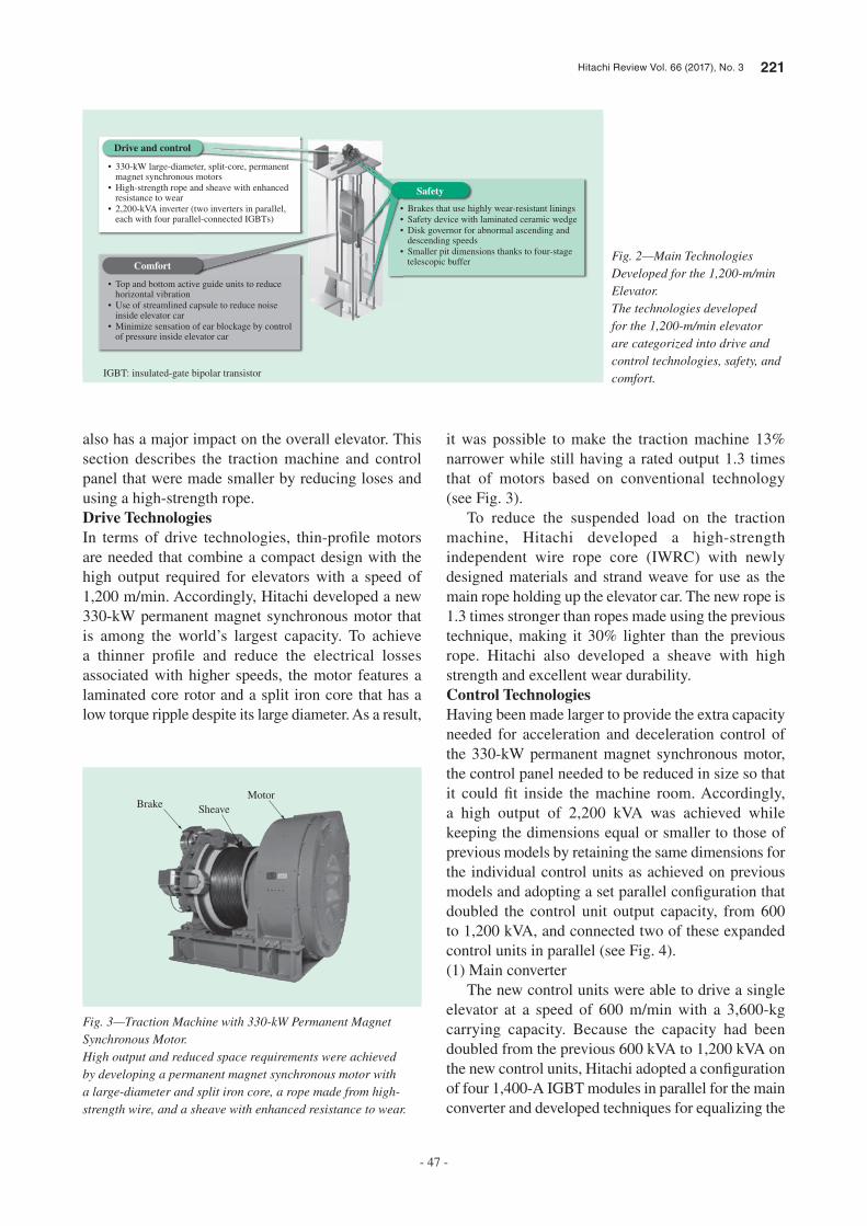
Fig. 2 shows the equipment and technologies
that needed to be developed for the world’s fastest
elevator. In particular, these included major technical
innovations in the form of a traction machine that
was made smaller thanks to lower losses and other
enhancements while still providing a high 330-kW
capacity, and a high-output (2,200 kVA) control unit
that was reduced to approximately half the size of the
previous model by using a drive circuit confi guration
with four insulated-gate bipolar transistors (IGBTs)
in parallel. Other new technologies developed by
Hitachi to maintain user comfort when traveling at
1,200 m/min were the use of top and bottom active
guide units to halve the amount of vibration caused by
bumps in the guide rails, and air pressure adjustment
technology for elevator cars to alleviate the sensation
of ear blockage(6).
Drive and Control Technologies to Attain a
Speed of 1,200 m/min
Elevators that travel at high speeds require larger
equipment because of the resistance and losses that
occur. Moreover, the greater weight of the rope
required in taller buildings with longer elevator travel
Kasumigaseki Building
Shinjuku Sumitomo Building
Tokyo Metropolitan Government Buildings
Testing (810 m/min)
Mito elevator research tower
(90 m)
New elevator research tower
(213 m)
Shanghai World Financial Center
(China)
AL HAMRATOWER(Kuwait)
19600
500
1,000
(m/min)
1970 1980 1990 2000
* Two-story elevator
2010
480*
600
1,200
540
300
(year)
Fig. 1—History of Hitachi’s Ultra-High-Speed Elevators.The graph shows the history of elevator speeds from the late 1960s to the present day.
Hitachi Review Vol. 66 (2017), No. 3 221
- 47 -
also has a major impact on the overall elevator. This section describes the traction machine and control panel that were made smaller by reducing loses and using a high-strength rope.Drive TechnologiesIn terms of drive technologies, thin-profi le motors are needed that combine a compact design with the high output required for elevators with a speed of 1,200 m/min. Accordingly, Hitachi developed a new 330-kW permanent magnet synchronous motor that is among the world’s largest capacity. To achieve a thinner profi le and reduce the electrical losses associated with higher speeds, the motor features a laminated core rotor and a split iron core that has a low torque ripple despite its large diameter. As a result,
it was possible to make the traction machine 13% narrower while still having a rated output 1.3 times that of motors based on conventional technology (see Fig. 3).
To reduce the suspended load on the traction machine, Hitachi developed a high-strength independent wire rope core (IWRC) with newly designed materials and strand weave for use as the main rope holding up the elevator car. The new rope is 1.3 times stronger than ropes made using the previous technique, making it 30% lighter than the previous rope. Hitachi also developed a sheave with high strength and excellent wear durability.Control TechnologiesHaving been made larger to provide the extra capacity needed for acceleration and deceleration control of the 330-kW permanent magnet synchronous motor, the control panel needed to be reduced in size so that it could fi t inside the machine room. Accordingly, a high output of 2,200 kVA was achieved while keeping the dimensions equal or smaller to those of previous models by retaining the same dimensions for the individual control units as achieved on previous models and adopting a set parallel confi guration that doubled the control unit output capacity, from 600 to 1,200 kVA, and connected two of these expanded control units in parallel (see Fig. 4).(1) Main converter
The new control units were able to drive a single elevator at a speed of 600 m/min with a 3,600-kg carrying capacity. Because the capacity had been doubled from the previous 600 kVA to 1,200 kVA on the new control units, Hitachi adopted a confi guration of four 1,400-A IGBT modules in parallel for the main converter and developed techniques for equalizing the
• 330-kW large-diameter, split-core, permanent magnet synchronous motors
• High-strength rope and sheave with enhanced resistance to wear
• 2,200-kVA inverter (two inverters in parallel, each with four parallel-connected IGBTs)
Drive and control
Comfort
• Brakes that use highly wear-resistant linings• Safety device with laminated ceramic wedge• Disk governor for abnormal ascending and
descending speeds• Smaller pit dimensions thanks to four-stage
telescopic buffer
• Top and bottom active guide units to reduce horizontal vibration
• Use of streamlined capsule to reduce noise inside elevator car
• Minimize sensation of ear blockage by control of pressure inside elevator car
Safety
IGBT: insulated-gate bipolar transistor
Fig. 2—Main Technologies Developed for the 1,200-m/min Elevator.The technologies developed for the 1,200-m/min elevator are categorized into drive and control technologies, safety, and comfort.
MotorBrake Sheave
Fig. 3—Traction Machine with 330-kW Permanent Magnet Synchronous Motor.High output and reduced space requirements were achieved by developing a permanent magnet synchronous motor with a large-diameter and split iron core, a rope made from high-strength wire, and a sheave with enhanced resistance to wear.

222 Development of Ultra-High-Speed Elevator that Achieved the World’s Fastest Elevator with a Speed of 1,200 m/min
- 48 -
current across these four IGBTs, reducing losses, and improving cooling performance.(2) Control circuit
As well as increasing the number of rotations per minute, the 1,200-m/min elevator has a larger number of poles due to its larger diameter, and this means it has a higher motor current frequency. In particular, because the problem of current control delay arises when compensation for dead time in the upper and lower IGBT arms is performed by software, the resulting distortion of the current waveform with higher fi fth- and seventh-order harmonics becomes a source of noise and vibration. To deal with this, Hitachi developed a technique that limits current waveform distortion to 1% or less by adjusting the phase of the dead time compensation voltage based on the motor current frequency.
The control characteristics of the traction machine (incorporating the new motor) and control panel were tested using a ground-based equivalence test rig to confi rm that the speed, motor torque, and current behaved normally (see Fig. 5).
The spring constant of the main elevator rope falls signifi cantly when the distance of travel reaches the 500-m range. This results in problems due to stretching of the rope such as low-frequency vibration of the elevator car, stop position errors, or the fl oor level being offset when people enter and exit the elevator car. In response, Hitachi drew on past experience and simulation-based testing to establish a way to control the fl oor level alignment with high precision.(3) Panel confi guration
Because the higher capacity of the control panel made its overall dimensions larger and heavier, the
3
Main drive circuit 1
Main drive circuit 2
Signalingdevice
Converter/inverter 1
Converter/inverter 2
Inverter control
Motor current referenceThree-phase dual-winding
PM motor
M
Elevator car
i1
i2Current difference reference
Current differencecontrol
Current sumcontrolConverter
control
Powersupply
PM: permanent magnet
Fig. 4—Control System Confi guration.The confi guration achieves high capacity by using a dual inverter (two independent main drive circuits connected in parallel) with sum and difference current control used to balance the two inverter currents.
1,200 m/min
2 s
Torque measurement
Motor 1 current
Motor 2 current
Power supply current
Speed feedback (elevator speed)
Fig. 5—Control Characteristics of 1,200-m/min Elevator.To determine the control characteristics, a ground-based equivalence test rig that simulates the inertial mass and load of the elevator was used to test operation for a travel distance of 600 m and a speed of 1,200 m/min.
Main drive circuit 2
Main drive circuit 1
Signaling device
Fig. 6—Control Panel.The three panels are installed separately and, from left to right, house main drive circuit 2, a signaling device, and main drive circuit 1, respectively. Separate panels house the mains power connection and reactor.

Hitachi Review Vol. 66 (2017), No. 3 223
- 49 -
developed a vertical active system with upper and lower active guide units that have accelerometers and actuators installed at four locations (top, bottom, left, and right) (see Fig. 8). The control system was built to be able to suppress different modes of vibration by designing it using the H∞ control technique to allow for sensitivity to horizontal vibration due to people and variations in the elevator parameters.
Testing on a vibrator test rig demonstrated that the new vertical active system can suppress rotational as
confi guration was divided by function to make it easier to work on during production and to allow for transportation to the machine room and construction (see Fig. 6). A unit confi guration with each phase in a separate unit was adopted for the drive circuit converters and inverters, with improvements also made to maintenance, including the use of a special-purpose trolley to pull the units out for easy inspection or replacement. Consideration was also given to the reliability of parts supply, and major components such as the printed circuit boards used for control functions were standardized with lower-rated mass-produced models.
Comfortable Elevators That Can Be Used
with Peace of Mind Even at Ultra-High Speed
Over Long Travel
At a speed of 1,200 m/min (72 kph), even minute bumps or warping in the guide rails have a major impact on elevator car vibration. The sensation of ear blockage resulting from the large pressure changes that occur in skyscrapers is also a source of greater user discomfort. Accordingly, Hitachi undertook development to improve these aspects of user comfort.Techniques for Reducing Elevator Car VibrationThe method used in the past to reduce horizontal vibration of the elevator car involved an active guide unit that detected vibrations using an accelerometer attached to the bottom of the car and used an actuator in the guide unit on the underside of the car to suppress the vibrations by controlling the spring force. At 1,200 m/min, however, the periodic vibrational disturbances due to rail misalignment are shifted to a higher frequency, and these are prone to generating higher-order modes of vibration that include pitching and other rotational modes as well as translational vibration (see Fig. 7). To deal with this, Hitachi
Translational Yaw Pitch
Rotational
Primary Secondary Tertiary
Fig. 7—Elevator Car Vibration Modes.The diagrams represent the primary, secondary, and tertiary vibration modes that pose a problem at very high speeds.
Elevator car Lower guide unit
Upper guide unit
Guide roller
Actuator
Active controller
Accelerometers
Active guide unit
System configuration Active guide unit
Fig. 8—Confi guration of Vertical Active System.A single controller coordinates control of the accelerometers and active guide units that are fi tted at four locations on the elevator car. The active guide units use an actuator to control the force pushing against the rail.
Time (s)
(a) Translational mode
Elev
ator
car
acc
eler
atio
n(m
/s2 )
Elev
ator
car
acc
eler
atio
n(m
/s2 )
Time (s)
(b) Rotational mode (pitch)
210
−0.1−0.05
00.050.1
0.15
−0.1−0.05
00.050.1
0.15
3 4 5
210 3 4 5
Control offActive control (bottom only)Active control (top and bottom)
Control offActive control (bottom only)Active control (top and bottom)
Fig. 9—Vibration Suppression by Vertical Active System.Whereas it is impossible to suppress rotational modes of vibration when active guide units are only provided at the two bottom locations, rotational modes can be controlled if active guide units are installed at the top, bottom, left, and right.

224 Development of Ultra-High-Speed Elevator that Achieved the World’s Fastest Elevator with a Speed of 1,200 m/min
- 50 -
speed. Accordingly, to suppress interior noise and reduce vibration, the counterweight was fi tted with a streamlining cover and an opening that reduces wind pressure by about 30%.
The noise reduction measures relating to the transmission path involved both, improving the acoustic insulation in the ceiling, side walls, and
well as translational modes of vibration, and that this ability to suppress a number of different modes of vibration works even when higher speeds cause the frequency of vibration to increase (see Fig. 9).Techniques for Reducing Noise in Elevator CarFaster elevator speeds increase the level of aerodynamic noise, causing more noise to propagate into the interior of the elevator car. The predicted increase in interior noise when changing from 600 m/min to 1,200 m/min was more than 15 dB, reaching a level similar to that experienced when standing next to a major highway. Minimizing this increased interior noise level requires suppression measures for both the noise source and transmission path.
To reduce noise at its source, Hitachi used computational fl uid dynamics techniques acquired through development work in the railway industry to evaluate the surface pressure fluctuations that cause aerodynamic noise, and developed a streamlined capsule that reduces these fl uctuations by approximately 50% compared to previous models (see Fig. 10). Moreover, because an elevator car is subject to increased horizontal vibration when passing its counterweight, experiencing wind pressure that increases with the square of the speed, reducing the noise and vibration caused by this passing is one of the challenges associated with increasing elevator
Door
Capsule
(a) Previous elevator car (b) Elevator car encased in capsule
Small
Large
Pressure change
Fig. 10—Use of Computational Fluid Dynamics to Determine Changes in Elevator Car Surface Pressure.The analysis found that encasing the elevator car in a streamlined capsule with a curved profi le, including on the door side, reduced the area subject to large pressure changes.
Airflow(schematic diagram)
Elevator car model
Fig. 11—Wind Tunnel Testing of Scale Model.The reduction in noise from adopting the streamlined capsule was determined by evaluating the aerodynamic noise from a 1/12 scale model of the elevator car.
Fig. 12—Elevator Car Capsule.The capsule shape was developed based on the results of testing using computational fl uid dynamics and the wind tunnel.

Hitachi Review Vol. 66 (2017), No. 3 225
- 51 -
changes in air pressure. To solve this problem, Hitachi developed a control technology with two degrees of freedom in which feedforward control is used for a fast response and control tolerance is minimized by combining feedback control with the generation of control commands in a way that takes account of the change in volume of structural components due to pressure differences. This succeeded in making air pressure control both accurate and responsive (see Fig. 14).
Safety Features for Ultra-High-Speed
Operation
Safety devices and systems development practices that can cope with high elevator speeds are among the challenges that need to be overcome to ensure the safety performance of the 1,200-m/min elevator. A new brake, safety device, overspeed governor, oil buffer, and electronic safety systems were developed for the elevator.BrakeWhile the elevator brake is normally used to hold the elevator car in position when stopped, it is also required to brake the motion of the car and bring it to a safe halt in the event of a power outage or other emergency.
Whereas the heating of the brake lining during an emergency stop reaches no more than 200°C on normal elevators, the friction heating of the brake lining when engaged at a speed of 1,200 m/min can exceed 400°C
other parts of the car to reduce transmitted noise, and developing an airtight car by minimizing gaps around the door and elsewhere to reduce airborne noise transmission.
Testing in a wind tunnel and on actual elevators verifi ed that these techniques had succeeded in reducing internal noise (see Fig. 11 and Fig. 12).Reduction of the Sensation of Ear Blockage Caused by Air Pressure ChangesThe changes in air pressure associated with taller buildings and faster speeds can cause user discomfort in elevator cars by causing the sensation of ear blockage, and the effect of pressure changes on the human body are more severe in skyscrapers of 500 m or more. Because this sensation of ear blockage is more noticeable when the elevator is descending than when it is ascending, it is necessary to place a limit on the descent speed.
Moreover, to reduce this discomfort, Hitachi adopted a method of controlling air pressure inside the elevator car that prevents the sensation of ear blockage from becoming more severe by forcing a rapid change in car air pressure to prompt users to swallow, which helps equalize the pressure in their ears. Testing of the rate of change in air pressure and the sensation of ear blockage was performed by using an air pressure simulator to conduct sensory evaluations (see Fig. 13).
To control the interior air pressure, Hitachi developed an air pressure control system made up of a pressurizer and a depressurizer mechanism. The diffi culty with this air pressure control system was that it needed to minimize control tolerance while still providing the fast response needed to achieve rapid
Fig. 13—Air Pressure Simulator.This simulator is used to replicate the changes in air pressure in an elevator in a skyscraper.
Fig. 14—Testing of Ability to Control Pressure Difference between Interior and Exterior of Elevator Car at Guangzhou CTF Finance Centre.The graph on the left shows a comparison of the internal air pressures for a traveling elevator in the Guangzhou CTF Finance Centre when control is on and off respectively. The graph on the right shows a comparative evaluation of the command values and observed values for internal air pressure when control is enabled.
Control onControl off
Command pressure valuesObserved pressure values
Time Time
(a) Air pressure change profile (b) Observed values with air pressure control
Cha
nge
in a
ir p
ress
ure
Inte
rior/e
xter
ior p
ress
ure
diff
eren
ce

226 Development of Ultra-High-Speed Elevator that Achieved the World’s Fastest Elevator with a Speed of 1,200 m/min
- 52 -
To deal with elevators that have different ascending and descending speeds, development was undertaken by fi tting separate speed detectors on the front and rear of the overspeed governor so that the same unit could be used for the two different speeds [see Fig. 15 (b)]. The descending speed detector needs to be set to a lower speed than the ascending speed detector, and therefore Hitachi constructed it to disconnect the descending speed detector when the elevator is ascending so that it is not activated by mistake. As well as maintaining safety, this also reduces the amount of space required.Oil BufferThe oil buffer is installed at the bottom of the hoistway (the pit) to halt the elevator and cushion the impact when it reaches the bottom.
The greater impact force resulting from the faster elevator speed means that the height of the oil buffers needs to be increased. Using the old design, a 1,200-m/min elevator would require an oil buffer of 24 m or more, causing extra construction work and making future replacement diffi cult. Hitachi resolved this problem by developing an oil buffer that uses a telescopic confi guration with a four-stage plunger to shorten its overall height, to 15 m or less in this case (see Fig. 16).Electronic ETSDAn emergency terminal speed-limiting device (ETSD) monitors the elevator car location and speed as it
for short periods. Accordingly, through improvements to the compounding agent and the shape of the braking surface, Hitachi developed a brake lining that is able to bring the elevator car to a safe halt even if it gets as hot as 400°C.Safety DeviceThe safety device fi tted to elevator cars is used to bring the car to a halt if it exceeds its rated speed by applying a friction brake to the rails. Decelerating an elevator traveling at 1,200 m/min to a full halt requires approximately 4.8 times as much braking energy as Hitachi’s previous largest-capacity safety device.
Hitachi developed a laminated ceramic wedge that is able to withstand the heat and wear caused by braking and to bring the elevator car to a halt without exceeding the maximum rate of deceleration specifi ed by the regulations. It also adopted a dual brake confi guration for the safety device, with separate upper and lower brakes to ensure that the required braking force can be achieved while also making the safety device smaller [see Fig. 15 (a)]. By conducting drop tests on the elevator research tower (described below), Hitachi satisfi ed the requirement to perform braking reliably twice using the same brake as specifi ed by European norms and Chinese standards, and acquired certifi cation.Overspeed GovernorAn overspeed governor is a speed detector that engages the safety devices (brake and safety devices) when it detects abnormal elevator acceleration.
Descent speed detector (ascent detector is on rear side)
Ceramicwedge
Pulley
Catchweight
(a) Safety Device (b) Overspeed Governor
Fig. 15—Safety Device and Overspeed Governor.The safety device grips the guide rails to brake the 1,200-m/min elevator in the event of an emergency and the overspeed governor detects the elevator car speed.
Fig. 16—Oil Buffer for 1,200-m/min Elevator.Hitachi reduced the size of the pit by approximately 9 m by developing a four-stage telescopic oil buffer.

Hitachi Review Vol. 66 (2017), No. 3 227
- 53 -
machine room and starting work on the fl oor above. Through close coordination of schedules between the construction work in China and the traction machine manufacture and shipment from Japan, delivery and installation in the machine room (at an elevation of 470 m) were completed quickly and safely, without delaying construction (see Fig. 17).
Joint Assembly Test of Elevator Car Prior to
Installation
The 1,200-m/min elevator cars are equipped with the new internal pressure control system and the vertical active system. Moreover, the streamlined capsule for reducing noise in the elevator car needs to be installed without leaving any gaps between the capsule and car.
To ensure that local workers with little experience of installing special elevator cars would be able to complete the installation on schedule, the test assembly of a complete elevator car was undertaken at the Japan factory. By allowing the work procedures to be checked, assembling a complete elevator car at
approaches the end of the hoistway and decelerates the car if its speed at a specifi ed distance from the end of the hoistway exceeds a specifi ed limit.
On past ETSDs, location was determined using a photoelectric device on top of the elevator car that detected when it moved past a shielding plate in the hoistway, while car speed was detected by the mechanical operation of a switch in the governor. Unfortunately, it proved diffi cult to build practical ETSDs of this type that worked at faster speeds because of the increased number of shielding plates in the hoistway and more complex governor mechanism.
Instead, Hitachi developed an electronic ETSD that uses an encoder in the governor to routinely and continuously monitor car location and speed, and incorporates a control panel to determine whether the elevator is operating in an acceptable range. The electronic ETSD has dual encoders and control panels (power supply, printed circuit boards, microcomputer), with each system monitoring the other to ensure a high level of safety and reliability.
CONSTRUCTION TECHNIQUES
Important tasks during the installation of a 1,200-m/min elevator include hoisting up a traction machine that weighs more than 20 t, installing approximately 200 guide rails that infl uence elevator ride comfort, and correctly assembling the complex array of elevator car components. At the Guangzhou CTF Finance Centre, construction staff from Hitachi Elevator (China) Co., Ltd. worked together under the supervision of construction staff from Japan to develop effi cient installation and construction techniques. The work was undertaken by a project organization coordinated between Japan and China.
Delivery of Fully Assembled Traction
Machines
Traction machine installation usually involves lifting the machine into place using a hoist. In this case, however, because the high-capacity traction machines (including the mount) weigh more than 20 t, it was decided to install them fully assembled. That is, to speed up the installation process, the traction machine and mount were assembled on the ground and then the completed unit was lifted into place using a construction tower crane.
Installing the traction machines fully assembled meant that the work needed to be done during the short time window between completing the fl oor of the
Fig. 17—Delivery of Fully Assembled Traction Machine.The photograph shows a traction machine and mount (with a combined weight of more than 20 t) being lifted up to the machine room after being assembled on the ground.

228 Development of Ultra-High-Speed Elevator that Achieved the World’s Fastest Elevator with a Speed of 1,200 m/min
- 54 -
the compressive force is high enough it causes small amounts of deformation in the rails and in the joints between rails. This compressive force also makes it diffi cult to correct for warping after installation (see Fig. 19).
In the past, Hitachi has used rail clips for skyscrapers that allow the guide rails to slip along their supporting brackets if enough force is applied to them in the axial direction. To further reduce the compressive force experienced by the rails in this latest project, Hitachi developed new clips that minimize the amount of load needed before guide rail slipping occurs, thereby reducing the level of compressive force and progressive deformation of the guide rails and making tasks like correcting guide rail warping easier. This ensured the proper installation of the guide rails in the building.
EVALUATION TRIALS AND ONSITE TESTING
To cope with the numerous test requirements for the various different types of equipment, the development included conducting evaluation trials of this equipment that involved both testing the 1,200-m/min elevator in the new elevator research tower and conducting emulation testing on a ground-based equivalence test rig. For those checks that are diffi cult to perform in practice, system testing was conducted on an evaluation system that incorporated simulation techniques developed by Hitachi and used parameters obtained from testing of the actual elevator (see Fig. 20).
the factory prior to installation ensured that the actual on-site construction could be completed accurately (see Fig. 18).
Guide Rail Construction Technique
Skyscrapers tend to shrink over time under the weight of installed equipment and of the building itself. The cumulative effect of the small amounts of shrinkage at each fl oor places a compressive load on the elevator guide rails via the brackets to which they are mounted. This also occurs during guide rail installation, and if
Fig. 18—Assembly of Complete Elevator Car.The photograph shows the trial assembly of a complete elevator car at Mito Works together with construction site workers.
Dial gauge
Guide rail
Joint
Hydraulic jack
Rail clip
Fig. 19—Guide Rail Compression Test Rig.Testing was used to determine the effect on things like rail warping of the anticipated compressive load on the guide rails due to progressive deformation (settling) of the building.
Fig. 20—Overview of Elevator System Test.Precise elevator system testing was made possible by using a combination of simulation and tests on actual elevators.
Testing onelevator research tower
Emulation testing onequivalence test rig
PC and computer simulation
System testing of elevator with a speed of 1,200 m/min and a travel distance in the 600-m range
PC: personal computer

Hitachi Review Vol. 66 (2017), No. 3 229
- 55 -
and forward-backward directions when traveling at 1,200 m/min being similar to that of previous elevators (see Fig. 23). The elevators were also put through various tests, including internal pressure control, internal noise level, and fl oor stopping accuracy, to demonstrate that the 1,200-m/min elevator satisfi ed
Testing on Ground-based Equivalence Test
Rig
The ground-based equivalence test rig (see Fig. 21) incorporates equipment for simulating inertial mass under different conditions for things like elevator car weight and distance of travel. It uses included emergency brake testing and testing the performance of the traction machine and control panel operating together under conditions equivalent to an elevator with a speed of 1,200 m/min and a travel distance of 600 m.
Operating Trials on New Elevator Research
Tower
The new 213-m high elevator research tower (see Fig. 22) was used to evaluate fl oor level accuracy and vibration during acceleration and deceleration, and also for elevator car testing to assess measures for minimizing vibration and noise when traveling at very high speed, including the streamlined capsule for reducing wind noise when moving and the active guide for reducing elevator car vibration due to guide rail warping. It was also used to test the safety device, overspeed governor, oil buffer, and other safety mechanisms.
Test Results for 1,200-m/min Elevator
Having completed testing using simulation and the above test equipment, a speed of 1,200 m/min was achieved on the actual elevator (with a travel distance of 440 m) in May 2016.
A high level of ride comfort was achieved with a level of elevator car vibration in the vertical, horizontal,
Fig. 22—New Elevator Research Tower.The 213-m elevator research tower is located at Hitachi’s Mito Works, and was built with the aim of representing Hitachi as global No. 1 in elevators.
1,200 m/min
Elevator speed
Horizontal vibration
Forward-backward vibration
Vertical vibration
Fig. 23—Operation Profi le of 1,200-m/min Elevator at Guangzhou CTF Finance Centre.The graphs show the operation and car vibration profi les measured on-site for the elevator traveling at 1,200 m/min.
Fig. 21—Ground-based Equivalence Test Rig.The test rig can be used to simulate a variety of conditions on the ground, including the loaded weight and inertial mass of the elevator.

230 Development of Ultra-High-Speed Elevator that Achieved the World’s Fastest Elevator with a Speed of 1,200 m/min
- 56 -
(3) T. Nakagawa et al., “World’s Fastest Elevator (1,010 m/min),” Toshiba Review 57, No. 06 (2002) in Japanese.
(4) H. Matsuoka et al., “Development of Large Transportation and High Speed Elevator,” Hitachi Hyoron 88, pp. 944–947 (Dec. 2006) in Japanese.
(5) A. Omiya et al., “World-leading Elevator Research Tower and New Elevator Technology for Next Generation of Urban Vertical Mobility Infrastructure,” Hitachi Review 60, pp. 106–111, (Apr. 2011).
(6) T. Nakayama, “Technology Development for the Ultra-high-speed Elevator with a Speed of 1,200 m/min,” Elevcon 2016 (May 2016).
the performance criteria. As a result, the elevator passed government inspection and certifi cation testing for Chinese national certifi cation [Guobiao (GB) standards] in August 2016.
CONCLUSIONS
The 1,200-m/min elevator supplied to the Guangzhou CTF Finance Centre (see Fig. 24) entered service in May 2016 and was shown to be the world’s fastest.
In the future, Hitachi plans to serve the taller and larger buildings that are in demand from overseas markets in particular by utilizing the new technologies and know-how developed for the 1,200-m/min elevator and by providing building environments that are secure, comfortable, and convenient.
REFERENCES
(1) H. Miyao et al., “Control of 300 m/min Gearless Elevators for Kasumigaseki Building,” Hitachi Hyoron 50, pp. 838–841 (Sep. 1968) in Japanese.
(2) M. Shigeta et al., “Super-high Speed Elevators (810 m/min),” Hitachi Hyoron 75, pp. 437–442 (Jul. 1993) in Japanese.
Fig. 24—Guangzhou CTF Finance Centre.The photo shows the building under construction in Guangzhou, China. Hitachi’s 1,200-m/min elevator was already operating at the time.

Hitachi Review Vol. 66 (2017), No. 3 231
- 57 -
Yoshiki Higashida
Global Big Project Department, Installation Management Division, Global Elevator & Escalator Division, Building Systems Business Unit, Hitachi, Ltd. He is currently engaged in the project coordination of important global customers.
Takashi Abe
Elevator Development Department, Global Development Division, Global Elevator & Escalator Division, Building Systems Business Unit, Hitachi, Ltd. He is currently engaged in the coordination of mechanical development of elevators. Mr. Abe is a member of The Japan Society of Mechanical Engineers (JSME).
Yosuke Kawamura
Elevator Development Department, Global Development Division, Global Elevator & Escalator Division, Building Systems Business Unit, Hitachi, Ltd. He is currently engaged in the mechanical development of elevators.
Keizo Nakamura
Engineering Company, Hitachi Elevator (China) Co., Ltd. He is currently engaged in the coordination of elevator installation and maintenance in China.
Xie Yi Xin
Engineering Company, Hitachi Elevator (Guangzhou) Co., Ltd. He is currently engaged in the coordination of elevator installation in China.
Atsushi Arakawa, Dr. Eng.
Power Electronics Systems Research Department, Center for Technology Innovation – Controls, Research & Development Group, Hitachi, Ltd. He is currently engaged in the development of vibration control and noise reduction technologies for elevators. Dr. Arakawa is a member of the JSME.
Hideka Matsuoka
Elevator Development Department, Global Development Division, Global Elevator & Escalator Division, Building Systems Business Unit, Hitachi, Ltd. He is currently engaged in the coordination of overall elevator development.
Naoto Ohnuma
Elevator Development Department, Global Development Division, Global Elevator & Escalator Division, Building Systems Business Unit, Hitachi, Ltd. He is currently engaged in the coordination of electrical development of elevators. Mr. Ohnuma is a member of the Institute of Electrical Engineers of Japan.
Tetsuya Nakayama
Elevator Development Department, Global Development Division, Global Elevator & Escalator Division, Building Systems Business Unit, Hitachi, Ltd. He is currently engaged in the mechanical development of elevators.
Yue Zheng Guan
Sales Headquarters, Hitachi Elevator (China) Co., Ltd. He is currently engaged in the sale of elevators in China.
Chen Song Xin
Engineering Company, Hitachi Elevator (China) Co., Ltd. He is currently engaged in the coordination of elevator installation in China.
ABOUT THE AUTHORS