development of the can crusher machine che … · development of the can crusher machine che mohd...
TRANSCRIPT

DEVELOPMENT OF THE CAN CRUSHER MACHINE
CHE MOHD AKHAIRIL AKASYAH B CHE ANUAR
Report submitted in partial fulfillment of the requirements
for the award of Diploma in Mechanical Engineering
Faculty of Mechanical Engineering
UNIVERSITI MALAYSIA PAHANG
NOVEMBER 2008

i
SUPERVISOR DECLARATION
“I declare that I have read this thesis and in my opinion, this thesis is enough to fulfill
the purpose for the award for the Diploma of Mechanical Engineering from the aspects
of scope and quality.”
Signature : ……………………………
Supervisor : EN. ZULKIFLI B AHMAD @ MANAP
Date :

ii
STUDENT DECLARATION
I declare that this report entitled “Development of the Can Crusher Machine” is the
result of my own research except as cited in the references. The report has not been
accepted for any degree and is not concurrently submitted in candidature of any other
degree.
Signature : ……………………………
Name : CHE MOHD AKHAIRIL AKASYAH B CHE ANUAR
ID Number : MB06007
Date :

iii
ACKNOWLEDGEMENTS
Alhamdulillah, I would like to express my thankfulness to Allah s.w.t to giving
me all the strength in fulfilling and completely this final year project. All the praise and
blessing be upon Prophet Muhammad s.a.w. I would like to thank to those who had been
involved whether directly or in directly in helping me to complete my final year project.
It could not have been written and produced without the help of many people.
Special appreciation is goes to my lovely parents, Mr. Che Anuar b Che
Muhammad and Mrs. Normah binti Hassan. Not forgotten to my family who gave
support at all times. My appreciated is also extended to Mr. Zulkifli b Ahmad @ Manap
who acts as my supervisor. Thank for supervision and encouragements. I also would like
to thank all my friend who always been listening my problems during the period to
finish this dissertation. All your kindness is very much appreciated.

iv
ABSTRACT
Designing and fabrication the can crusher machine is a product that fulfills the
customer needs. This project uses many materials such as sheet metal, hollow steel bar
and others. Overall, this project involves many processes, starting from the design
concept, fabrication and assembling procedures. Even though there are many types of
the can crusher machine in the market, the completion of this new model provides a
more practical usage.

v
ABSTRAK
Meraka bentuk dan membuat mesin pengemik tin merupakan salah satu produk
untuk kepentingan pengguna. Projek ini meggunakan pelbagai jenis bahan seperti
kepingan besi, besi berongga dan sebagainya. Keseluruhan projek ini melibatkan
berbagai-bagai proses bermula dengan idea konsep rekabentuk, pemotongan bahan,
mereka bentuk dan fabrikasi. Walaupun mesin pengemik tin seperti ini telah banyak di
pasaran, namun kelainan dalam penyelesain produk ini telah dilakukan bagi memastikan
ianya lebih praktikal untuk digunakan.

vi
TABLE OF CONTENTS
CHAPTER TITLE PAGE
SUPERVISOR DECLARATION i
STUDENT DECLARATION ii
ACKNOWLEDGEMENT iii
ABSTRACT iv
ABSTRAK v
TABLE OF CONTENT vi
LIST OF TABLES x
LIST OF FIGURES xi
LIST OF APPENDIXES xiii
1 INTRODUCTION
1.1 Project Synopsis 1
1.2 Project Problem Statement 1
1.3 Project Objective 2
1.3.2 General Objective 2
1.3.3 Specific Project Objective 2
1.4 Project Scope 2
1.5 Project Planning 3

vii
2 LITERATURE REVIEW
2.1 Introduction 6
2.2 Project Review 6
2.2.1 Foot Operated Can Crusher 7
2.2.2 Can Crusher Bin Single Pack 8
2.2.3 6 Can Aluminium Can Crusher 9
2.2.4 Easy Pull Can Crusher and Storage
System 10
2.3 CNC Shearing Machine 11
2.4 Drilling 13
2.4.1 Introduction 13
2.4.2 Hammer Drill 13
2.4.3 Drill Press 14
2.5 Vertical Bandsaw 16
2.5.1 Introduction 16
2.5.2 Powermatic Bandsaw 16
2.5.3 The Control 17
2.5.3.1 Start/stop 17
2.5.3.2 High/Low Range 17
2.5.3.3 Bandsaw Speed 17
2.6 Gas Metal Arc Welding (GMAW) 17
2.6.1 Introduction 17
2.6.2 MIG Welding Benefit 19
2.7 Rivet 19
2.7.1 Introduction 19
2.7.2 Blind Rivet 20
2.8 Bending Machine 21
2.8.1 Introduction 21
2.8.2 CNC Bending 22
2.8.3 Specification for CNC Bending 22

viii
3 METHODOLOGY
3.1 Project Flow Chart 24
3.2 Design 27
3.2.1 Concept A 28
3.2.2 Concept B 29
3.2.3 Concept C 30
3.3 Concept Generation and Evaluation 31
3.4 Finalize Design 32
3.5 Product Design Specification 33
3.6 Engineering Drawing Of The Design 34
3.7 Fabrication Process 38
3.7.1 Getting Material 38
3.7.2 Measuring and Marking Process 39
3.7.3 Cutting Process 39
3.7.4 Drilling Process 41
3.7.5 Bending Process 42
3.7.6 Mechanical Joining Process 42
3.7.7 Painting Process 44
4 RESULT AND DISCUSSION
4.1 Introduction 45
4.2 Result 45
4.2.1 Introduction 45
4.2.2 Product Specification 48
4.2.3 Types Of Defects 48
4.3 Discussion 50

ix
5 RECOMMENDATION AND CONCLUSION
5.1 Introduction 51
5.2 Recommendation 51
5.3 Conclusion 52
REFERENCES
APPENDIX A-B

x
LIST OF TABLES
TABLE NO. TITLE PAGE
1.0 Gantt Chart 5
3.1 Pugh Selection Concept 31
4.5 Table of Product Specification 48

xi
LIST OF FIGURES
FIGURE NO. TITLE PAGE
2.1 Foot Operated Can Crusher 7
2.2 Can Crusher Bin Single Pack 8
2.3 6-Can Aluminium Can Crusher 9
2.4 Easy Pull Can Crusher and Storage system 10
2.5 CNC Shearing Machine 11
2.6 Shearing Process Feature 12
2.7 A Hammer Drill 14
2.8 Drill Press 15
2.9 A Vertical Bandsaw 16
2.10 Basic Structure of MIG Nozzle 18
2.11 Three Blind Rivet: 1/8’’, 3/32’’ and 1/16’’ 21
2.12 A CNC Bending Machine 22
3.1 Project Flow Chart 26
3.2 Concept A 28
3.3 Concept B 29
3.4 Concept C 30
3.5 Final Design 32
3.6 Body of the Can Crusher 34
3.7 Handle of the Can Crusher 35
3.8 Hopper of the Can Crusher 35
3.9 Stand of the Can Crusher 36
3.10 Dustbin of the Can Crusher 36
3.11 Can Crusher Assembly 37
3.12 Material at FKM Lab 38

xii
3.13 Measuring and Marking 39
3.14 Cut The Workpiece 40
3.15 The Workpiece Done 41
3.16 Make Hole 41
3.17 Workpiece Done 42
3.18 Join the Hollow Steel Bar Using MIG 43
3.19 Join the Sheet Metal and Hollow Steel Bar 43
3.20 Painting the Can Crusher 44
4.1 Isometric View 46
4.2 Front View 46
4.3 Top View 47
4.4 Side View 47
4.5 Bead at the Body 59
4.6 The Body not parallel 49

xiii
LIST OF APPENDICES
APPENDIX TITLE PAGE
A Detail Drawing Part 54
B Machine Tool and Equipment 57

CHAPTER 1
INTRODUCTION
1.1 PROJECT SYNOPSIS
This project contains of designing and fabrication of can crusher machine.
There have many differences between this can crusher with current design in market
place. This project is to develop and improving it performance as well so that there
has no doubt about the design and concept. This design required little forces to crush
the aluminum cans, can crush a can at a time. In this project, it needs lot of skills and
information and also knowledge such as Computer Aided Design software
(AutoCad), Solidworks software, using shearing machine, Truma Bend V Series
(bending machine), vertical bendsaw, bench work and welding process. This design
obviously would help the user. So, this design would through much process before it
get into prototype term in order to achieve the objectives and off course customer
need.
1.2 PROJECT PROBLEM STATEMENT
Usually we use leg to stamp the cans. This method is very dangerous because
can make injure for us, but nowadays many can crusher was produce. But most of the
current product was attached at the wall. So the current product is not portable. Then
the current products are troublesome and difficult because it make user feel not
suitable as well. Beside that most of products also not have hopper to prepare the can
before crush and not have storage for the crushed cans.

2
1.3 PROJECT OBJECTIVES
1.3.1 General Objective
Diploma final year project objectives is to practices the knowledge and skill
of the student that have been gathered before solving problem using academic
research, to born an engineer that have enough knowledge and skill. This project also
to complete the subject on this semester. The student also can be explore the
advanced machine before involves in industries. The project otherwise will be
produce and train student capable of doing work with minimal supervisory and more
independent in searching, detailing and expanding the knowledge and experiences.
The project also will generate student that have capability to make a good research
report in thesis form technical writing.
1.3.2 Specific Project Objective
This project will be following these objectives;
i. To design and fabricate the can crusher that required low force
to crush the cans.
ii. To design and fabricate the can crusher that can crush a can at
a time a.
iii. To design and fabricate the can crusher that has storage to
locate the can after crush.
1.4 PROJECT SCOPE
In order to finish this project require precise scope of work and proper plan
need to be followed because this project must through various process before it
would be produce. Beside that this project title is new idea which is come from
instructor engineer in lab and as the knowledge isn’t entirely covered in classes or
lab. So it give us advantages to learn new process to produce this product and
absolutely we could find lot of advantages neither we are realized or not. These are
scope of work in this project:-

3
i. Literature review about the design from any possible resource
ii. Design the model of can crusher
iii. Fabricate the design using material that been selected
iv. Test the design in demonstration
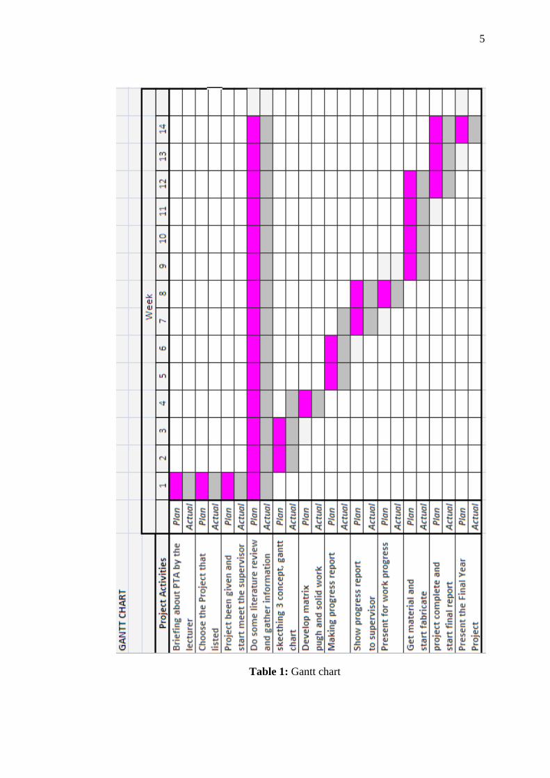
1.5 PROJECT PLANNING
This project is beginning with meet supervisor to collect information and
otherwise search from via internet, books and survey at market, this literature review
must do for every week. The finding of information not will be stop on a week but
continues along the way of this project because to get more information.
The Gantt chart (time management) and flow chart (process management)
will be developing on second week. This is done using Microsoft Excel using Gantt
chart system.
The week second and third, have to make three sketching. These sketching
based on the advantages and disadvantage product in marketing.
The Fourth week the Pugh analysis and matrix analysis will be developing.
The function of this analysis is to get a final design, from three designs any criteria
will be research to get good concept. After get a final design solid work will be start.
Just final design will use this software. Each part will be developed and lastly
the assembly part will be begun.
On weeks fifth and sixth the progress report will be start. Meeting with
supervisor on weeks seventh and eight gather data to complete progress report. That
week the mid presentations also start.
The getting material will be start after mid presentation. The process cutting
raw materials start on week nine. At the same time the fabrication also starts. The
planning process of fabrication around week’s nine until twelve.

4
After finish the process fabrication, the final report will be start. To complete
the report I will use format thesis 2008.The last presentation will be started on week
fourteen.
5
Table 1: Gantt chart

CHAPTER 2
LITERATURE REVIEW
2.1 INTRODUCTION
The purpose of this chapter is to provide a review of product in market. I will
make a comparison of other product in market. Substantial literature has been studied
on advantages and disadvantages of that product. However, little information can be
found on integrated durability evaluation methods. The example of evaluation I will
be develop is Pugh analysis and matrix analysis. The below is some product in
market.
2.2 PRODUCT REVIEW
Study about the current design is important in order to determine what the
product function really are and find out how it perform and getting out it advantages
for each and then compare with other product that been review already. In this
process, it is decided to study about three current designs in market now in order to
gain information that could help me created my new design as well.

7
2.2.1 Foot Operated Can Crusher
Figure 2.1: Foot Operated Can Crusher
• Advantages
i. Suitable for both steel and aluminum cans
ii. Reduces cans by up to 85%
iii. Slip and non marking feet
iv. Sturdy all metal construction
v. Suitable for cans up to 500ml
• Disadvantages
i. No hopper
ii. No have container to storage the crushed cans
iii. Need more time to crush many cans

8
2.2.2 Can Crusher Bin Single Pack
Figure 2.2: Can Crusher Bin Single Pack
• Advantages
i. Crushes and self-ejects standard aluminum cans
ii. Stores more than 400 cans and conveniently fits into small spaces
iii. Hand operated crusher allows you to crush can with easy
• Disadvantages
i. No hopper ii. Need more time to crush many cans
iii. Heavy iv. High force need to operate

9
2.2.3 6-Can Aluminum Can Crusher
Figure 2.3: 6-Can Aluminum Can Crusher
• Advantages
i. Have hopper ii. Can crushed 6 can at a times
iii. Little force need to operate
• Disadvantages
i. Not portable ii. Not have storage
10
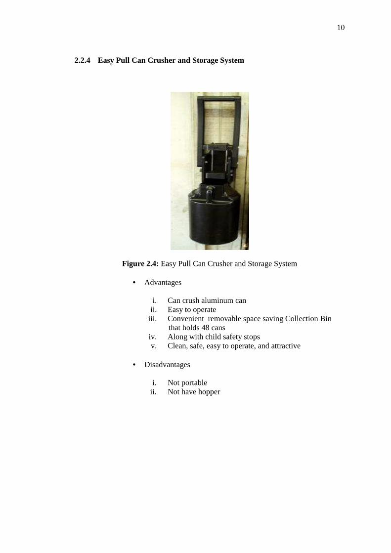
2.2.4 Easy Pull Can Crusher and Storage System
Figure 2.4: Easy Pull Can Crusher and Storage System
• Advantages
i. Can crush aluminum can ii. Easy to operate
iii. Convenient removable space saving Collection Bin that holds 48 cans
iv. Along with child safety stops v. Clean, safe, easy to operate, and attractive
• Disadvantages
i. Not portable
ii. Not have hopper

11
2.3 CNC SHEARING MACHINE
Shearing is a process for cutting sheet metal to size out of a larger stock such
as roll stock. Shears are used as the preliminary step in preparing stock for stamping
processes, or smaller blanks for CNC presses. During the shearing process, an upper
blade and a lower blade are forced past each other with the space between them
determined by a required offset.
Material thickness ranges from 0.125 mm to 6.35 mm (0.005 to 0.250 in).
The dimensional tolerance ranges from ±0.125 mm to ±1.5 mm (±0.005 to ±0.060
in). The shearing process produces a shear edge burr, which can be minimized to
less than 10% of the material thickness. The burr is a function of clearance between
the punch and the die (which is nominally designed to be the material thickness), and
the sharpness of the punch and the die.
The illustration at next page had shown a two-dimensional look at a typical
metal shearing process. Note how the upper shear blade fractures the metal
workpiece held in place by the work holding devices. The sheared piece drops away.
Figure 2.5: CNC shearing machine

12
Typically, the upper shear blade is mounted at an angle to the lower blade
that is normally mounted horizontally. The shearing process performs only
fundamental straight-line cutting but any geometrical shape with a straight line cut
can usually be produced on a shear. Metal shearing can be performed on sheet, strip,
bar, plate, and even angle stock. Bar and angle materials can only be cut to length.
However, many shapes can be produced by shearing sheet and plate.
Materials that are commonly sheared include:
i. Aluminum
ii. Brass
iii. Bronze
iv. Mild steel
v. Stainless steel
Figure 2.6: Shearing process features

13
2.4 DRILLING
2.4.1 Introduction
A drill is a tool with rotating drill bit used for drilling holes in various
materials. Drills are commonly used in woodworking and metalworking. The drill bit
is gripped by a chuck at one end of the drill, and is pressed against the target material
and rotated. The tip of the drill bit dose the work of cutting into the target material,
slicing off thin shaving ( twist drills or auger bits ) or grinding off small particles ( oil
drilling )
2.4.2 Hammer Drill
The hammer drill is similar to a standard electric drill, with the experience
that is provided with a hammer action for drilling masonry. The hammer action
maybe engaged or disengaged as required. The hammer action is cheap but delicate.
It uses two cam plates to make chuck accelerate towards to the work. However
because of the relative masses of the chick bit and the remainder of the drill the
energy transfer is inefficient and will fail to penetrate harder materials and vibrates
the operator’s hand. The cams were fast. Compare this to a rotary/ pneumatic
hammer drill where just the bit is accelerate to the work is sucking the bit inwards.
Large cam hammer drills, especially transverse motor, are crude in their
action. The energy delivered in each stroke is highly variable. The cheaper drill will
smash its way through the work and vibrate the surroundings which can cause lots of
collateral damage.

14
Figure 2.7: A hammer drill
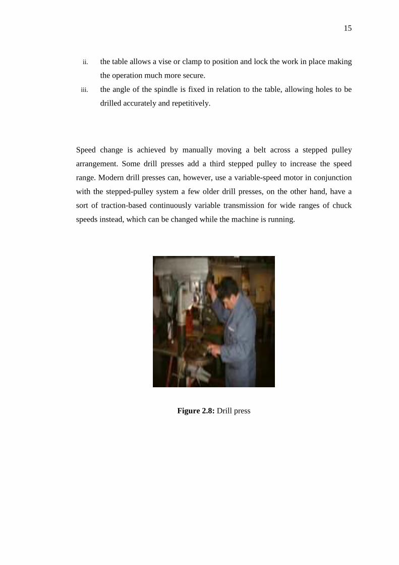
2.4.3 Drill Press
A drill press (also known as pedestal drill, pillar drill, or bench drill) is a fixed
style of drill that may be mounted on a stand or bolted to the floor or workbench. A
drill press consists of a base, column (or pillar), table, spindle (or quill), and drill
head, usually driven by an induction motor. The head has a set of handles (usually 3)
radiating from a central hub that, when turned, move the spindle and chuck
vertically, parallel to the axis of the column. The table can be adjusted vertically and
is generally moved by a rack and pinion however, some older models rely on the
operator to lift and reclamp the table in position. The table may also be offset from
the spindle's axis and in some cases rotated to a position perpendicular to the column.
The size of a drill press is typically measured in terms of swing. Swing is defined as
twice the throat distance, which is the distance from the center of the spindle to the
closest edge of the pillar. For example, a 16-inch (410 mm) drill press will have an 8-
inch (200 mm) throat distance.
A drill press has a number of advantages over a hand-held drill:
i. less effort is required to apply the drill to the work piece. The movement of
the chuck and spindle is by a lever working on a rack and pinion, which gives
the operator considerable mechanical advantage.
15
ii. the table allows a vise or clamp to position and lock the work in place making
the operation much more secure.
iii. the angle of the spindle is fixed in relation to the table, allowing holes to be
drilled accurately and repetitively.
Speed change is achieved by manually moving a belt across a stepped pulley
arrangement. Some drill presses add a third stepped pulley to increase the speed
range. Modern drill presses can, however, use a variable-speed motor in conjunction
with the stepped-pulley system a few older drill presses, on the other hand, have a
sort of traction-based continuously variable transmission for wide ranges of chuck
speeds instead, which can be changed while the machine is running.
Figure 2.8: Drill press

16
2.5 VERTICAL BANDSAW
Figure 2.9: A vertical bandsaw
2.5.1 Introduction
Vertical band saws, also known as contour saws, perform metal removal jobs
that save time and material. Large sheets and bars of material can be cut to size or
shape without creating too many chips in a short period of time. Most materials, from
wood and plastics to aluminum and steel, can be cut on the two band saws in the
shop. Certain metals require specific saw bands in order to be cut, so check with
someone in the shop before cutting steels or hardened materials.
2.5.2 Powermatic Bandsaw
This bandsaw is used for cutting steel and stainless steel. The other band saw
in the shop should not be used to cut these harder materials.

17
2.5.3 The Controls
-starts/stop
-high / low range
-bandsaw speed
2.5.3.1 Start s/stop
The green button will start the bandsaw, the red button will stop it. The
bandsaw will coast to a stop, so wait until the blade has stopped moving before
removing your part or scrap pieces from the table.
1) High / low range
The bandsaw has a high speed and low speed gear that can be changed with
this lever. The bandsaw must be stopped before attempting to change the range.
2) Bandsaw Speed
The speed of the bandsaw may also be changed with this hand wheel. The
bandsaw must be running to adjust the variable speed.
2.6 GAS METAL ARC WELDING (GMAW)
2.6.1 Introduction
Welding is a fabrication process that joins materials, usually metals or
thermoplastics, by causing coalescence. This is often done by melting the work
pieces and adding a filler material to form a pool of molten material that cools to
become a strong joint. This is in contrast with soldering and brazing, which involve
melting a lower-melting-point material between the work pieces to form a bond
between them, without melting the work pieces.

18
The method joining that able to fabricate and assembled the can crusher is
Metal Inert Gas (MIG) welding. The equipment used in GMAW is a welding gun; a
wire feed unit, an electrode wire and a shielding gas supply. When the control switch
is turned on the wire feed, electrical power and gas flow are initiated. This causes an
electric arc to be struck. The gas nozzle is used to direct the welding gas evenly into
the welding zone.
The Figure 2.10 below shows the basic structure of MIG nozzle
Figure 2.10: Basic Structure of MIG Nozzle
(1) Torch Handle (2) Molded phenolic dielectric (3) shielding gas nozzle (4) Contact
tip (5) Nozzle output fac
To perform gas metal arc welding, the basic necessary equipment is:
i. a welding gun
ii. a wire feed unit
iii. a welding power supply
iv. an electrode wire
v. a shielding gas supply

19
2.6.2 MIG Welding Benefit
i. All position capability
ii. Higher deposition rates than SMAW
iii. Less operator skill required
iv. Long welds can be made without starts and stops
v. Minimal post weld cleaning is required
2.7 RIVET
2.7.1 Introduction
A rivet is a mechanical fastener. Before it is installed it consists of a smooth
cylindrical shaft with a head on one end. The end opposite the head is called the
buck-tail. On installation the rivet is placed in a pre-drilled hole. Then the tail is
"upset" (i.e. deformed) so that it expands to about 1.5 times the original shaft
diameter and holds the rivet in place. To distinguish between the two ends of the
rivet, the original head is called the factory head and the deformed end is called the
shop head or buck-tail.
Because there is effectively a head on each end of an installed rivet it can support
tension loads (loads parallel to the axis of the shaft); however, it is much more
capable of supporting shear loads (loads perpendicular to the axis of the shaft). Bolts
and screws are better suited for tension applications.
Fastenings used in traditional wooden boat building like copper nails and clinch bolts
work on the principle of the rivet but they were in use long before the term rivet was
invented. So, where they are remembered, they are usually classified among the nails
and bolts respectively.

20
2.7.2 Blind Rivets
Blind rivets are tubular and are supplied with a mandrel through the center.
The rivet assembly is inserted into a hole drilled through the parts to be joined and a
specially designed tool used to draw the mandrel into the rivet. This expands the
blind end of the rivet and then the mandrel snaps off. (These are also commonly
called pop rivets from the sound and feel through the setting tool when the mandrel
breaks.) These types of Blind rivets have non-locking mandrels and are avoided for
critical structural joints because the mandrels may fall out, due to vibration or other
reasons, leaving a hollow rivet that will have a significantly lower load carrying
capability than solid rivets. Furthermore, because of the mandrel they are more prone
to failure from corrosion and vibration.
Prior to the adoption of blind rivets, installation of a solid rivet typically
required two assemblers: one person with a rivet hammer on one side and a second
person with a bucking bar on the other side. Seeking an alternative, inventors such as
Carl Cherry and Lou Huck experimented with other techniques for expanding solid
rivets. Unlike solid rivets, blind rivets can be inserted and fully installed in a joint
from only one side of a part or structure, "blind" to the opposite side.
Due to this feature, blind rivets are mainly used when access to the joint is
only available from one side. The rivet is placed in a pre-drilled hole and is set by
pulling the mandrel head into the rivet body, expanding the rivet body and causing it
to flare against the reverse side. As the head of the mandrel reaches the face of the
blind side material, the pulling force is resisted, and at a predetermined force, the
mandrel will snap at the break point of the mandrel. A tight joint formed by the rivet
body remains, the head of the mandrel remains encapsulated at the blind side,
although variations of this are available, and the mandrel stem is ejected.

21
The rivet body is normally manufactured from one of three methods:
i. Wire, the most common method
ii. Tube, common in longer lengths, not normally as strong as wire
iii. Sheet, least popular and generally the weakest option.
Figure 2.11: Three aluminium blind rivets: 1/8", 3/32", and 1/16"
2.8 BENDING MACHINE
2.8.1 Introduction
Press brakes and bending machine are used to bend and fold metal by
pressing it into a die. There are several types of press brakes and bending machines.
Example include a hydraulic press brake, folding equipment, bending machine, press
brake tooling, CNC brake press and a sheet metal press brake. A hydraulic press
brake is designed for both specialized sheet metal work and continuous production
application. A hydraulic press brake is designed to handle tough industrial
production jobs from single-cycle operations to automated cell components. Folding
equipment can be used to stiffen new metal panels that would otherwise flap around,
and to put lips on pieces of sheet that would normally need screws passed through
the front face. A bending machines forms angels in sheet metal. Press brake tooling

22
is used in cold-forming metal sheets or strips into desired sections. A CNC brake
press is a computer numerically controlled, fully automated brake press with
extensive bending capacity and networking function. A sheet metal press brake is
used to bend.
2.8.2 CNC Bending
Metal bending forms angle in sheet metal.
Figure 2.12: A CNC Bending
2.8.3 Bending Designed Guidelines
i. The minimum inner radius recommended is approximately one material
thickness for most materials.
ii. The minimum flange width should be at least 4 times the material thickness
plus the bending radius.
iii. Holes or slot should be located a minimum of 3 stock thickness plus the bend
radius. If it necessary to have holes closer, then the hole or slot should be
extended beyond the bend line.

23
2.8.4 Specification for CNC Bending
i. Material – most ductile metals
ii. Alternative machine – none
iii. Tooling – CNC Bending requires only software program tooling.
iv. Reducing cost – reduce the number of bends used in design. Design parts to
pack efficiently. For example, in designing a large box consider marking the
sides of the box separate with bolted flanges. Avoid complex bend
combinations. It can avoid the costs of the bending by adding slots in place
of the bend combinations.
CHAPTER 3
METHODOLOGY
3.1 PROJECT FLOW CHART
From the flow diagram on Figure 3.1, this project started with discussion
with supervisor about title after got from lecturer. This discussion covering project
overview supervisor and throw out opinion that related about title and supervisor
instruct to proposed a certain design and concept before go up to next step.
Then go to literature review about the title. The most important in these
manner is a determined the project scope, objective and project planning so that we
could easy get a clear overview. Then study and gather information related to the
design and these entire task been done through study from internet, journal and other
source.
After gather and collect all related information and obtain new idea and
knowledge about the title, the project would continue with the design process. In this
stage, the knowledge and idea should throw out in sketching process. After several
design sketched, the best design would be choose among previous design so that we
could carry on designing process. Then the selected design would be transfer to
engineering drawing using SolidWork software in order to improve it capability and
for analysis process.
After that material preparation which is has been confirm initially. Purpose of
this process is a to determine the suitable and strength material follow the product
and design requirement. This process covering purchased material, measuring