development of single crystal beta alumina membrane
TRANSCRIPT
DEVELOPMENT OF SINGLE CRYSTAL BETA ALUMINA MEMBRANE
J. T. A. Pollock R. Stormont
F. Wald
Tyco Laboratories, Inc. Bear Hill
Waltham, Massachusetts 02 154
Preparzd for
NATIONAL AERONAUTICS AND SPACE ADMINISTRATION
NASA Lewis Research Center Cleveland, Ohio 44 13 5
Contract NAS 3 - 144 10
J. Stuart Fordyce, Project Manager

* For sale by the National Technical Information Service, Springfield, Virginia 22151
,
NASA-C-168 (Rev. 6-71)
3. Recipient's Catalog No.
5. Report Date
June 1971 6. Performing Organization Code
8. Performing Organization Report No.
10. Work Unit No.
11. Contract or Grant No.
NAS 3-14410 13. Type of Report and Period Covered
Contractor Report 14. Sponsoring Agency Code
1. Report No.
NASA CR-72982
2. Government Accession No.
4. Title and Subtitle
DEVELOPMENT OF SINGLE CRYSTAL BETA ALUMINA MEMBRANE
7. Author[s)
J. T. A. Pollock, R. Stormont and F. Wald
9. Performing Organization Name and Address
q c o Laboratories, Inc. Bear Hill Waltham, Mass 02154
12. Sponsoring Agency Name and Address
National Aeronautics and Space Administration Washington, D. C., 20546
15. Supplementary Notes
Project Manager, Dr. J. Stuart Fordyce, Direct Energy Conversion Division, NASA Lewis Research Center, Cleveland, Ohio
16. Abstract
The feasibility of using a novel crystal growth technique developed by Tyco Laboratories, Inc., for the growth of p-alumina sheaths is investigated. Melt containment components fabricated from Mo, W, and Ir a re used and it i s concluded that only Ir offers sufficient thermodynamic com- patibility with the melt. Rods and tubes a r e grown and characterized using metallographic and X- ray diffraction techniques. They a r e found to be two phase, composed of p-alumina with an admix- ture of a-alumina. The appearance of the latter phase is due to sodium loss from the melt and it is suggested that 100% p-alumina tubes may be grown using apparatus allowing growth in inert gas pressures of up to 30 atm.
17. Key Words (Suggested by Author(s))
Beta alumina Solid electrolytes Batteries Crystal growth
18. Distribution Statement
Unclassified - unlimited
22. Price"
$3.00
21. No. of Pages
2 1 19. Security Classif. (of this report)
Unclassified 20. Security Classif. (of this page)
Unclassified
ABSTRACT
The feasibility sf using a novel crystal. growth te~hniqpe developed by Tyco
Laboratories, hc., for the growth of p-alumina sheaths is investigated. Melt con-
tainment cornpogents fabricated f r ~ m Mo, W, anq Ir a r e used and it is copcluded
that only Ir offers sufficient thenn~dynamic compatibility with the melt. Rods gnd
tubes a r e grown and characterized using metall~grapbic and X-ray diffraction tech-
niques. They a r e found to be two phase, composed ~f p-alumina with an admixture
of a -alumina. The qppearance of the latter phase ig due to sodium loss from the
melt and i t is suggested that 100% p-alumina tubes may be grown using apparatus
allowing growth in inert gas pressures of up to 30 am.
iii


Table of Contents
Page No .
ABSTRACT ................................................ iii
L SUMMARY .................................................
IL INTRODUCTION ............................................
..................... IIL APPARATUS AND BASIC EXPE RIMGNTAL PROCEDURES
......................................... IV . CRYSTAL GROWTH
V . CONCLUSIONS .............................................
Appepdix: REFRIS\TTS OF PUBLICATIONS DESCRIBING EDGE.DEFINElJ. l?II+Jbl- FED GROWTH


List of Illustrations
Figure No. Page No.
..................... 1. Quartz Furnace Assembly Incorporating Two 6 Window Ports
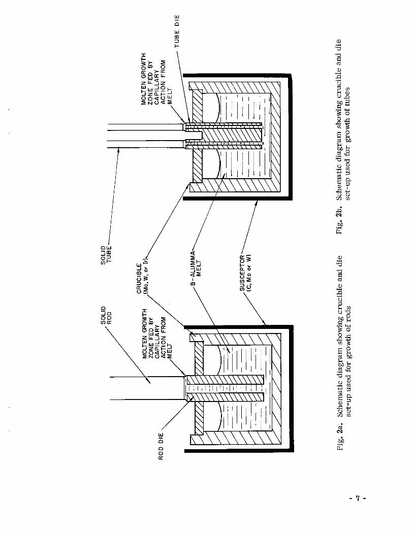
23. Schematic Diagram Showing Crucible and Die ..................... 7 Set-Up Used for Growth of Rods
2b. Schematic Diagram Showing Crucible and Die.. .,,................ 7 Set-Up Used for Growth of Tubes
...................................... 3. Crystal Growth Apparatus 8
.................. 4. p-Alymina Tubes Grown a t 8 to 11 In./Hr Using 13 Molybdenum Setups
......................... 5. p-A1 0 Rod Grown From Iridium Setup 2 3 16
......................... 6. p-A1 0 Rod Grown From Iridium Setup 16 2 3
............... 7. Laue Back Reflection Photograph of Area Shown in. . 1 7 Figs. 5 and 6
................ 8. Laue Back Reflection Photograph of Flat Surface of 1 7 Monofrax Hp-A1203 Sliver Platelet Shows { 0001) Plane of Hexagonal P-A1203
I. SUMMARY
The crystalline and electronic structure of 6 -alumina is such that, although
exhibiting negligible electronic conductivity below 300 "C, i t exhibits considerable
anistropy with respect to sodium ion conductivity. It has been proposed that it may
have important future application as a membrane for high energy batteries. Ford
Motor Company has demonstrated this potential with polycrystalline 0 -alumina
membranes. A s well as improvements in efficiency which would accrue from the
use of single crystal membranes, lower operating temperatures and freedom from
circuit failure due to intergranular processes a r e additional possible advantages.
Thus, the establishment of a method for the growth of single crystalline p-alumina is
of considerable interest.
The objective of the present program was to establish the feasibility of grow -
ing single crystal 6-alumina using the "edge-defined, film-fed growth" technique
developed by Tyco Laboratories which allows the growth from the melt of crystals of
predefined shape, such as tubes.
Crystal growth was carried out in an argon atmosphere using R F heating, and
melt and die components fabricated from Mo, W and Ir. Using single crystal seeds,
0.125 in. diameter rods and 0.20 in. 0.d. x 0.16 in. i.d. tubes were grown from the
melt at rates of up to 15 in./hr. As determined by Debye-Scherrer X-ray diffraction,
the material grown was p -alumina containing an admixture of a -alumina. Only iridium
components may be used without excessive errosion and dissolution of the crucible and
die material in the melt, and subsequent incorporation in the crystals grown. Rods
grown using I r components were free from contamination, and, although two phase,
exhibited single crystallinity a s determined by X-ray Laue diffraction, indicating
that the a - and p - phases were mutually oriented with respect to each other.
The major problem to be solved is loss of sodium from the melt by volatiliza-
tion during growth. This is the reason for the appearance of a -alumina in the samples
grown. It is suggested that a furnace be constructed such that p -alumina tubes may
be grown in inert atmosphere pressures of up to 30 atm, thus suppressing the loss of
volatile components during growth.
- 1 -


11. INTRODUCTION
p-alumina has for some time been in widespread use as a refractory mate-
r ia l in the form of cast byicka. More recently, it has been proposed that i t may
have important future application a s a membrane for high energy batteries. Ford
Motor Company has demonstrated this potential with polycrystalline p -alumina
membranes and a liquid sodium-liquid sulphur system. 1
The property of p-alumina which allows i t to be considered for this function is
the anistropy which is crystalline structure exhibits with respect to ionic conductivity, 2 electronic conductivity being essentially negligible in all directions. At room tem-
perature, it is virtually nonc~nducting along the c-axis of the hexagonal cell, yet has
a specific resistance of only 30 ohm-em a t right angles to this direction, i.e., along
the a-axis. Obvious advantages in efficiency compared with polycrystalline aggre-
gates will accrue from the use of single crystalline membranes of the correct orienta-
tion. Even if the polycrystalline aggregates' a r e of preferred orientation, the presence
of grain boundaries provides additional problems, since integranular processes may
occur, resulting in failure of the conducting path. Also, i t is possible that lower
operating temperatures may result from the use of single crystal materials. Thus,
the establishment of a method for the growth of single crystalline p-alumina is of
considerable interest.
The objective of the present program was to establish the feasibility of
growing single crystal p-alumina by making use of a novel crystal growing technique
developed by Tyco Laboratories, Inc. 394* This technique has been developed pri-
marily with the growth of sapphire (a! -alumina) and allows the growth of crystals
with constant, but almost arbitrary, cross~sect ional shape. In addition ta producing
single crystals, the method, if successfully applied to p-alumina, would allow the
production of p-alumina sheaths in forms most suited for battery use. These sheaths
would allow the fabrication of plates containing a minimum quantity of, for example,
liquid sodium. By this me th~d , the bulk of the s~diurn could be held in a container
away from the liquid cathode o r catholyte, and transported to the p-alumina sheath
for reaction by capillary action.
*See Appendix.

This report describes experiments and results whose goal was the establish-
ment of a melt growth approach to the production of single crystalline p-alumina
sheaths.
111. APPARATUS AND BASIC EXPERIMENTAL PROCEDURES
5 The double window-port quartz furnace assembly shown schematically in
Fig. 1 was used for all crystal growth experiments. Schematic diagrams of the set-
ups used for the growth of rods and tubes a r e presented in Fig. 2. The overall sys-
tem including furnace, stereomicroscope viewer, pulling system, etc., is shown
photographed in Fig. 3. An inert atmosphere, argon in the presept case, is main-
tained within the furnace, which consists of two concentric quartz tubes between
which cooling water flows. The melt and growth area is viewed directly through
either of the ports which allow essentially undistorted observation. The window-ports
a r e provided with a cover of optical quality glass, The inert gas flow (2) acts to
prevent oxide deposition on the inside of the window and thus mai~ta ins clean obser-
vation conditions. The two ports a r e separated by 120" of arc. They allow both
temperature measurements and control, and optical monitorivg of the growth proce-
dures. They a r e at angles of 90" and 60" to the furnace axis in order to provide addi-
tional observation freedom of the area of interest.
A 450- Kc induction unit is used to ra ise the crucible containing the melt to
the necessary growth temperature either by susception directly to the crucible or
a susceptor surrounding it. Crucibles and dies were fabricated from molybdenum,
tungsten, and iridium and will be described in the following appropriate sections.
The pulling mechanism may be simply considered a s two rigid parallel vertical
shafts on one of which is an a i r bearing connected to a plate with guide bearings
on either side of the opposite shaft. Using compressed ai r , the system is essen-
tially frictionless. A ball disk integrator and synchronous motor a r e used t~ move
the shaft holding the seed crystal. The length of growth available is - 30 in. and
constant growth speeds in the range 0.001 to 38 in./hr may be selected. In order to
maintain a beneficial f u n a c e atmosphere and to prevent backstreaming of a i r into
the system via the pulling rod exit, an expandable bellows arrangement was used
as shown in Fig. 3.

f G A S FLOW OUT
GAS
- I-
H2Q OUT - - FLOW (2) IN - GAS FLOW (2) IN
- GAS FLOW OUT
R.E COIL/
SUPPORT PEDESTAL
1 INERT GAS FLOW (1) IN
Fig. 1. Quartz furnace assembly incorporating two window ports
SO
LID
S
OL
ID
MO
LTE
N G
RO
WT
H
ZO
NE
F
ED
B
Y
CA
P1 L
LA
RY
C
AP
ILL
AR
Y
AC
TIO
N
FR
OM
--
TU
BE
DIE
Fig
. 2a
. S
chem
atic
dia
gra
m s
how
ing
cru
cib
le a
nd d
ie
Fig
. 2b
. S
chem
atic
dia
gra
m s
how
ing
cru
cib
le a
nd d
ie
set-
up
use
d f
or
gro
wth
of
rod
s se
t-u
p u
sed
fo
r gr
owth
of
tub
es
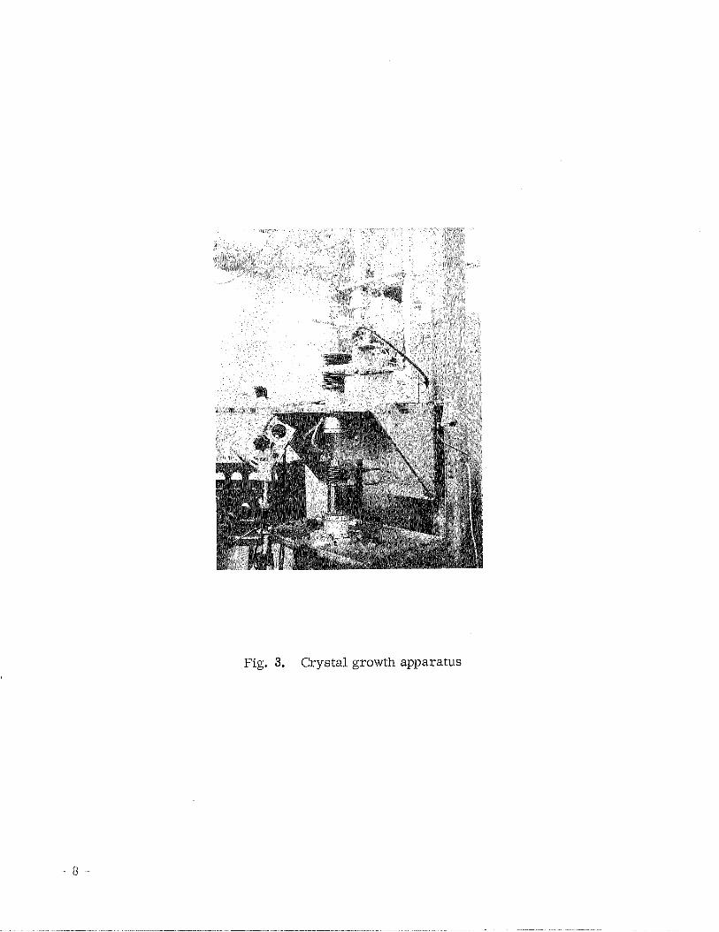
Fig. 3, Crystal growth apparatus

There is a continuing uncertainty with regard to the exact composition of
p-alumina, The material commonly obtainable in such form and known as Carborun-
dum Monofrax H -alumina contains 5.59 wt % Na20 and is therefore 11.1 = A1203:
Na20 in molar ratio. This material was used for many of the growth experiments. 6 However, Weber and Venero reported the composition of p-alumina as being A1203:
Na20 = 9: 1 with a congruent melting point at 1967 OC a 6 OC. Both 9: 1 and 11: 1
molar ratio material were prepared internally. Calculated stoichiometric mixtures
of Na2 C03 and A12 O3 were mixed and pressed into disks under a pressure of - 200
atm. These disks were placed in Pt crucibles and sintered at 1150 OC for 15 hr
under an oxygen atmosphere in a Burrel Box Furnace.
Rods and tubes were grown from p-alumina melt using the experimental tech- 3
nique a s described by LaBelle in a recent publication. The crystals grown were
examined using optical microscopy in transmitted and reflected light. The composi-
tion and occurrence of p-alumina in the crystals grown was determined using standard
Debye-Scherrer examination of powdered samples and comparing the pattern and line
intensities with standard films. Although the p-alumina pattern is complex and r e -
quires sophisticated interpretation, Laue X-ray back reflection photography was used
to study the crystallinity of the samples grown.


IV. CRYSTAL GROWTH EXPERIMENTS
A. Molybdenum Setups
The first growth experiments were carried out using molybdenum components
and Carborundum Monofrax H p-alumina as charge material. Three arrangements
of the crucible-susceptor were used in experiments aimed at the growth of 0.125 in.
diameter rods. These were:
1. Mo crucible, with RF susception directly to crucible
2. Identical Mo crucible inside a larger diameter Mo crucible,
with susception to the larger
3. Identical Mo crucible placed inside a graphite cylindrical sus-
ceptor in which the RF field was induced.
The modifications outlined above were introduced in order to arrive at the
optimum thermal operating conditions, i. e., the minimum melt temperature en-
vironment which would allow crystal growth.
p-alumina rods were grown from each of the setups at growth rates in the
range 2 - 15 in./hr using a small sliver of Monofrax H, nominally of c-axis orienta-
tion a s seed. Debye-Scherrer (D/S) examination of a powdered sample taken from
the rods revealed that they were mainly p-alumina with an admixture of a! -alumina.
Back reflection ~ a u e ' x - r a ~ photography indicated that some of the rods (or parts)
were single crystalline o r contained only a few grains. However, the rods were
dark, indicating Mo dissolution from the crucible setup, although Mo lines were
not observed in the D/S patterns. No chemical analysis was carried out, but visual
examination made it apparent that the rods grown from setup no. 3 were nearly
translucent and were of the best surface quality.
It was apparent during these experiments that vaporization of sodium or
sodium oxide was occurring during growth. It was primarily for this reason that
the bellows was introduced at the pulling shaft exit, thus allowing a slight positive

pressure to be maintained within the system. Also, the crucible setup was modified
to reduce the exposed surface area of the melt (from which sodium losses will take
place) to only the crystal growth area (diameter). This sodium loss is undoubtedly
the reason for the appearance of a! -alumina in these and other crystals grown.
A second series of experiments was carried out using Mo components and
the growth arrangement involving the graphite susceptor. A Mo tube die was fabri-
cated using rod and tube of matching dimensions. After machining, spacing, and
pinning of these basic components, a die which would allow the growth of tubes
0.200 in. 0.d. X 0.160 in. i .d was available. Charge material of composition A.1203:
NaZO = 9: 1 was used in an effort to compensate for sodium losses. A small single
crystal sliver was again used as seed. On bringing the setup to temperature, seeding
was successfully carried out and a tube grown a t - 9 in./hr (sample T I in Fig. 4).
The crucible was emptied and a tube over 2 1/2 in. long was obtained. Approximately
1 1/4 in. of this tube, the last section to be grown, had a smooth surface.
A second growth run was carried out using Carborundum Monofrax H p -alu-
mina (A1203:Na20 = 11: 1) a s charge material. A tube - 2 1/4 in. long was grown at
about 11 in./hr (sample T2 in Fig. 4).
It was observed that considerable erosion of the Mo die had taken place
during both of these growth experiments. However, by mechanical polishing, it
was possible to salvage the die for a further growth run. Two changes in the growth
procedure were introduced as possible means of reducing the die erosion. It was
considered that a possible reason for Mo die erosion during growth was excessive
radiant heat from the walls of the crucible. In an attempt to reduce this, a small
vertically slotted Mo pipe was placed around the die. The length of the pipe was
qualitatively judged so a s to produce a temperature gradient that would buffer the
excessive radiant heat, yet not reduce the thermal environment by an amount causing
difficulty in reaching growth conditions. Secondly, the crucible setup together with
the charge was placed in the furnace and flushed with helium overnight to ensure an
oxygen and moisture free starting environment. These changes produced no notice-
able improvements in either the loss of Na or Mo die erosion. A tube approximately
3 1/2 in. long, which failed to grow entirely cylindrical, was grown.
D/S X-ray diffraction patterns confirmed that samples taken from the begin-
ning, middle, and end of sample T I were p -alumina, containing a -alumina as a
second phase. Comparing line intensities with D/S patterns taken from rods, it
appeared that there was more a! -alumina present and that it increased a s the growth
of the tube progressed.
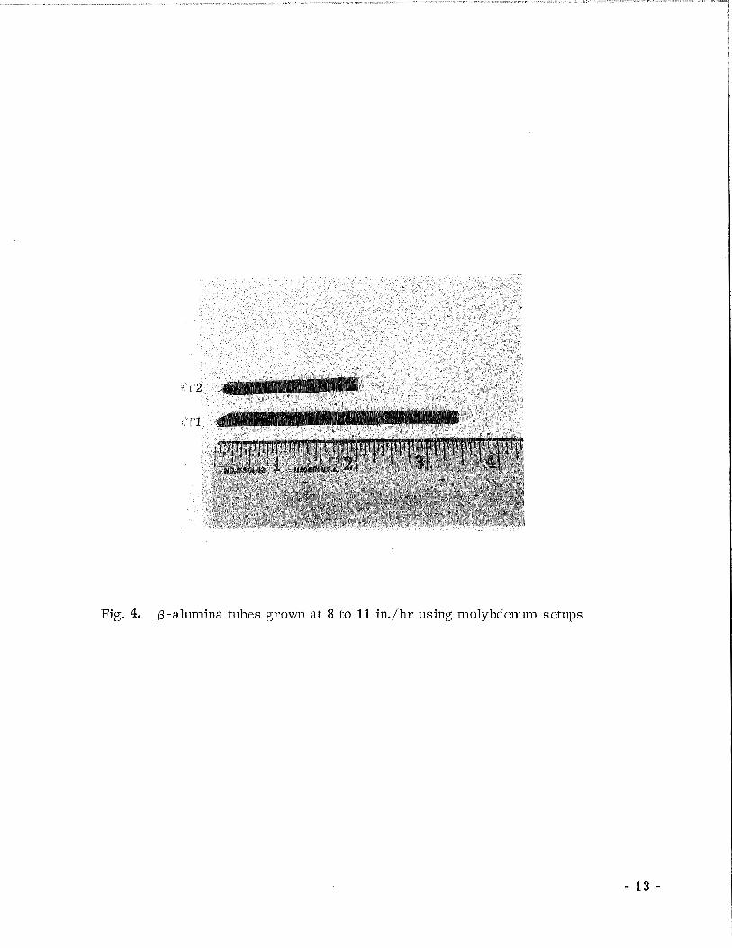
Fig. 4. p-alumina tubes grown at 8 to I1 in./hr using molybdenum setups
B. Tungsten S e t u ~ s
Experience with the growth of a! -alumina (sapphire) has shown that tungsten
components a r e thermodynamically more compatible. It was decided to check if
this was also true for p-alumina in an effort to reduce crucible and die dissolution
and later precipitation during crystal growth.
A complete growth setup was fabricated from tungsten (i.e., crucible and
die). This proved to a complex procedure due to the brittleness of tungsten, which
makes machining slow and difficult. Acid etching in HF:HN03 = 1: 1 proved to be
the only successful means of producing the thin walled parts of the die. The basic
components were then spaced and pinned to produce a W die which would allow the
growth of tubes 0.250-in. i.d. X 0.200-in. 0.d. A Mo susceptor was used.
Carborundum Monofrax H p -alumina was used as charge material and a
small single crystal sliver of the same material served as a seed. Thermal growth
conditions proved to be more difficult to achieve with W than with the Mo components. 2
\ This is probably related to the higher thermal conductivity of W, - 1 W/cm , com- 2 pared with - 0.65 W/cm for Mo, at 2000 "C. This means that the melt temperature
has to be raised to compensate for increased radiation losses. A small, dark .-
colored tube was grown which proved to be almost entirely a! -alumina. Also, 'the
walls of the tungsten crucible had been excessively attacked, possibly worse than
with Mo components.
It was concluded that W components could not be used, and that Ir was the
next logical choice.
C. Iridium Growth Setup
p-alumina rods were grown from an iridium crucible and die setup. The
latter proved to be compatible with the melt material, no metallographically detectable
erosion taking place.
A 0.625 in. diameter iridium crucible was used. The bottom end of the
0.125 in. diameter Lr rod die was pressed into an Lr disk which could be located ! ' .
a t the bottom of the crucible, thus maintaining the die in in a vertical position. 1 1 8
This method of mounting the die was used because the components normally in-
volved were not available in iridium and machining would have been costly. How-
ever, i t is not the most efficient setup design. In particular, it is unfavorable
from the point of view of creating a growth thermal environment at a low R F power
setting.

Two growth runs using Carborundum Monofrax H p-alumina as charge mate-
r ia l and a small sliver a s seed were carried out. During the second run, after in-
troducing heat shielding modifications, a rod about 2 in. long was grown. A piece of
material taken from the center of this rod was crushed and used to obtain a D/S pat-
tern. A mixture of p - and a -alumina was detected. The p-lines were more intense
(relative to the a! -lines) than with the samples grown from the Mo setups. It was
noted that during growth considerably less "smoking" was observed, despite the
more open nature of the growth setup and the higher heat input required to produce
the necessary growth conditions. Also examination of the setup after growth indi-
cated that no attack of the crucible or die had occurred. After growth, the melt
material remaining was a very pale blue color, due perhaps to back streaming of
Mo from the radiation -shielding.
Slices were cut out of the rod grown perpendicular to the growth direction
and just above the region used to obtain the D/S patterns. Five of these slices were
mounted and polished using standard metallographic techniques to - 0.004 in. thick.
Between cross polarizers in transmitted light, the slice exhibited a two-
phase distribution, taking up three-fold symmetry (Fig. 5). This was at first thought
to be the (0001) plane but, on rotation about the growth axis, the minority phase ex-
hibiting the three-fold symmetry was found to extinguish every 90". Using reflected
light, the same symmetry distribution was observed. It is evident that the phase
proportions a re about 60:40, although it is not possible to separate them into a! and
p a t this time. Using unpolarized light, the polished slices appeared as in Fig. 6
with no obvious sign of symmetry. These micrographs confirm the D/S evidence of
the two phase nature of the rods. /
Laue back reflection photographs taken from similar slices approximately
parallel to the growth direction a r e typical of single crystals and show no evidence
of the spot splitting which might be expected from a two-phase sample (Fig. 7).
This implies that the phases a r e oriented in the same direction. The ~aue'~hoto-
graph shows three-fold symmetry and was confirmed as being the (10il) plane found
in a -alumina. Thus, it appears that the p-alumina is oriented with respect to the
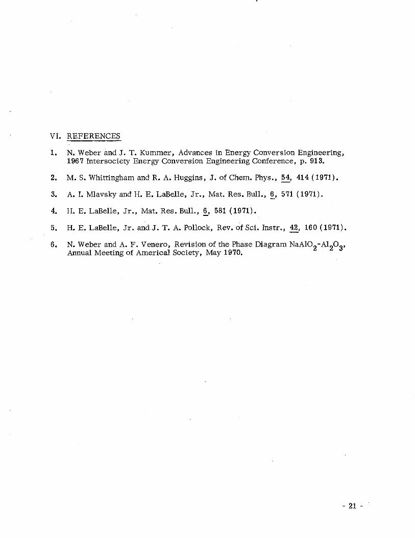
a -alumina structure. An example of the true p-alumina symmetry was obtained by
taking a Laudfrom a Monofrax H p-alumina sliver platelet. The platelet was X-
rayed on a flat face perpendicular to the growth plane wed, and the photograph is
shown in Fig. 8. The crystal face X-rayed is the (0001) plane of p-alumina and

Fig. E. @-A1203 rod grown from iridium setup (viewed parallel to growth direction in polarized reflected light at 75X)
Fig. 6. p-A1203 rod grown from iridium setup (viewed parallel to growth direction in relfected light at 75X)
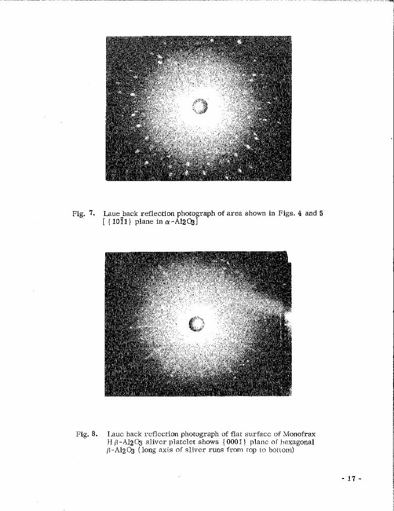
Fig. 7. Laue back reflection photograph of area shown in Figs. 4 and 5 [ { 10ilj plane in a-A12031
Fig. 8. Laue back reflection photograph of flat surface of Monofrax H 0-A1203 sliver platelet shows (0001 } plane of hexagonal p -A1203 ( long axis of sliver runs from top to bottom)

hexagonal six-fold symmetry with six mirror planes is evident. Py contrast, the
(0001) plane of a -alumina exhibits three-fold symmetry with three mirror planes.
The ~ a u e ) ~ h o t o ~ r a ~ h s from the platelets a r e fuzzy compared to the photo-
graphs obtained from the rod, even though a "single crystal" was used. An a-axis
~aue'could not be obtained from the platelets due to this excessive splitting.
The (10il) orientation of the rod grown, which is 18" from the axis of the
seed platelet, is probably due to a magnification of an original misalignment.

V. CONCLUSIONS
It has been demonstrated that melt growth of p-alumina sheaths using a novel
crystal growth technique developed by Tyco Laboratories, Inc. is feasible. Tube
and rods containing mixtures of p - and a! -alumina have been grown from components
fabricated from Mo, W, and Jr. It is concluded that, in regard to thermodynamic
compatibility with the p-alumina melt, only iridium components may be used without
excessive erosion and dissolution of the crucible and die material in the melt. Rods
grown using Ir setups were two phase, yet exhibited single crystallinity, indicating
that the phases were mutually oriented with respect to each other.
The major problem remaining to be solved is loss of sodium by volatilization
from the melt during growth. This is undoubtedly the reason for the appearance of
a! -alumina in the samples grown. It is suggested that a furnace be constructed such
that the p-alumina tubes may be grown under inert gas pressures of up to 30 atm,
since it has been demonstrated by other research that this is a suitable method f ~ r
suppressing the loss of volatile components during melt growth.
It is possible that, i f the ionic conductivity of the p-phase in the two-phase
structure is that of the stoichiometric single crystal, sQme advantages in mechanical
strength might accrue from the use of two-phase membranes. Also, control of the
alpha content could result in a material which would have value as a "graded seal" to
pure alumina, and have potential use in p~ae t ica l battery systems.

VI. REFERENCES
1. N. Weber and J. T. Kummer, Advances in Energy Conversion Engineering, 196 7 Intersociety Energy Conversion Engineering Conference, p. 91 3.
2. M. S. Whittingham and R. A. Huggins, J. of Chem. Phys., - 54, 414 (1971).
3. A. I. Mlavsky and H. E. LaBelle, Jr., Mat. Res, Bull., - 6, 571 ( 1971).
4. H. E. LaBelle, Jr., Mat. Res. Bull., - 6, 581 (1971).
5. H. E. LaBelle, Jr. and J. T. A. Pollock, Rev. of Sci. Instr., - 42, 160 ( 1971).
6. N. Weber and A. F. Venero, Revision of the Phase Diagram NaA102-M203, Annual Meeting of America1 Society, May 1970.


APPENDIX
REPRINTS OF PUBLICATIONS DESCRIBING
EDGE-DEFINED, FILM-FED GROWTH


Mat. Res. Bull. Vol. 6, pp. 571-580, 1971. Pergamon Press , Inc. Printed in the United States.
GROWTH OF CONTROLLED PROFILE CRYSTALS FROM THE MELT: PART I - SAPPHIRE FILAMENTS
H. E . LaBelle, Jr . and A . I. Mlavsky Tyco Laboratories, Inc.
Waltham, Massachusetts 02154
(Received May 27, 1971; Communicated by J. B. Goodenough)
ABSTRACT A crys ta l growth technique is described in which a tubular, annu- l a r , o r ribbon-shaped capillary orifice is used to maintain the liquid level coi~stant during growth and to determine the shape of the growing crystal. The orifice material must be wetted by, but chemically iloilreactive to the moltell phase of the crystal to be grown. Usiiig molybdenum orif ices and crucibles, single crystal sapphire filaments several hundred feet in length and diameters of . O l - .05 c m have been growl1 at speeds of 2 .5 - 5 cm/min; c -axis crys ta ls have beell grown a t r a t e s up to 20 cm/min, and a variety of other crys ta l orieiltatioils has been grown at speeds up to 2 .5 cm/min. Sapphire tubes, ribbons and multiple fila- ments have also been grown.
Over the past several years , we have been conceriied with the devel- opment of techniques for the coiitinuous growth of controlled profile single crys ta ls from the melt. During the course of this work, a succession of techniques has been developed such that we a r e now able to grow essentially contiiluous crystals (several hundred feet long in the case of filament) of a l -
most arbi trar i ly coiltrolled c r o s s section directly from the melt. The tech- niques have mostly been applied to the growth of a! -alumina although other materials including spinels, titanates, other oxides, metals, and ionic sal ts have a lso been grown.
In Part I of this se r i e s , we describe the basic technique by which coiltinuous sapphire filaments have been grown and we indicate the applica -
bility of the method to the growth of other materials and other shapes. In

5 72 SAPPHIRE FILAMENTS Vol. 6, No. 7
Part 11, ' ~ l l e of us (H. E . LaB. ) describes a refinement of the technique which
greatly aids in the accurate control of the dimensions of the growing crystal and which enhances a self -stabilizing feature of the growth. In Part 111, the basic theory of that method i s described, iilcluding a discussioll of the effect of the growth process on the morphology of filaments, particularly of a! - alumina. In Part IV, detailed experimental results on the growth morphology a re reported and compared with the theoretical predictions.
Part I: Sapphire Filaments
Techniques for the continuous melt growth of filaments have been previously reported. Thus, von Gomperz (1) grew metal filaments, Gaule and Pastore (2) grew germanium, and LaBelle and Mlavsky (3) reported the
growth of sapphire filaments. In all of these approaches, the crystal was pulled through a disc -like die located on the surface of the melt. The techni - que described here requires the use of a rigid capillary made from a material that i s wetted by, but nonreactive to the molten phase of the crystal to be grown. Use of the technique permits the growth of single crystal sapphire filaments in lengths of hundreds of feet; ribbons, tubes and other shapes a re also grown by a slight variation of the technique which has also been applied to the growth of materials other than a! -alumina.
Basic Approach
Previously we described a "floating orifice technique" (4) by which sapphire filaments of reasonably controlled geometry were grown from the melt. The orifice was fabricated from molybdenum which i s wetted by the melt and which"f1oats"on the surface thereof. A disadvantage of this techni - que in the preparation of coi~tii~uous filaments arises from the fact that the floating orifice continuously lowers as the filament i s grown and the melt depleted. Also, a rather elaborate temperature control i s required for con- tinuous growth over an extended period.
In the present technique (5), a capillary tube (typically fabricated from molybdenum) i s attached to the bottom of a crucible (also molybdenum)
in such a way that liquid is able to enter the bottom of the capillary, Because the contact angle, 8 , of molten alumina is less than 90°, liquid r ises in the capillary an amount, h cm, given by:
* "Growth of Controlled Profile Crystals From the Melt, " Parts I, 11, 111, and IV will be published in this Journal.
Vol. 6, No. 7 SAPPHIRE FILAMENTS 5 73
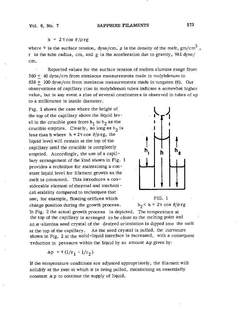
h = 2Ycos 8 / p r g
3 where Y is the surface tension, dyne/cm, p i s the density of the melt, gm/cm , r is the tube radius, cm, and g is the acceleration due to gravity, 981 dyne/ cm.
Reported values for the surface tension of molten alumina range from 360 -t - 40 dyne/cm from meniscus measurements made in molybdenum to 638 -k - 100 dyne/cm from meniscus measurements made in tungsten (6). Our observations of capillary r i s e in molybdenum tubes indicate a somewhat higher value, but in any event a r i se of several centimeters is observed in tubes of up to a millimeter in inside diameter.
Fig. 1 shows the case where the height of the top of the capillary above the liquid lev- e l in the crucible goes from hl to h2 a s the crucible empties. Clearly, so long a s h2 is
less than h where h = 2~ cos 8/p rg , the liquid level will remain at the top of the capillary until the crucible i s completely emptied. Accordingly, the use af a capil- lary arrangement of the kind shown in Fig. 1 provides a technique for maintaining a con - stant liquid level for filament growth a s the melt is consumed. This introduces a con- siderable element of thermal and mechani - cal stability compared to techniques that ' use, for example, floating orifices which FIG. 1
change position during the growth process. h2< h = 2Y cos B/prg
In Fig. 2 the actual growth process is depicted. The temperature at the top of the capillary is arranged to be close to the melting point and an a! -alumina seed crystal of the desired orientation is dipped into the melt
at the top of the capillary. As the seed crystal i s pulled, the curvarure shown in Fig. 2 at the solid-liquid interface is increased, with a consequent
reduction in pressure within the liquid by an amount Ap given by:
If the temperature conditions a r e adjusted appropriately, the filament will solidify at the rate at which it is being pulled, maintaining an essentially constant A p to continue the supply of liquid.
SAPPHIRE FILAMENTS Vol. 6, No. 7
I - . 7 . . i . - . . / - - - MOLTEN AUMINA - - --
FIG. 2 The growth process
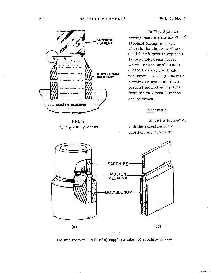
In Fig. 3(a), an arrangement for the growth of sapphire tubing i s shown wherein the single capillary used for filament i s replaced by two molybdenum tubes which a re arranged so a s to create a cylindrical liquid reservoir. Fig. 3(b) shows a
simple arrangement of two parallel molybdenum plates from which sapphire ribbon
can be grown.
Apparatus
Since the technique,
with the exception of the capillary mounted with -
MOLYBDENUM
(a (b)
FIG. 3
Growth-from the melt of a) sapphire tube, b) sapphire ribbon

Vol. 6, No. 7 SAPPHIRE FILAMENTS 5 75
in the crucible, is essentially identical to Czochralski growth, any standard melt growth furnace can be used. The pulling mechanism, however, may require modification especially to enable the growth and spooling of continu - ous filaments.
The specific apparatus we have used for most of our experiments II U I I i s shown diagrammatically in Fig. 4. The molybdenum capillary assembly is supported in a molyb- denum crucible which i s used to c~i l ta in the melt. The crucible i s positioned in a double jacketed, water cooled quartz chamber and heated by R F of 450 KHz from a 20 kw generator. The inside of the tube is maintained in a helium or argon atmosphere . FIG. 4
Crystal growth apparatus
For the growth of ribbons, tubes, and other stiff shapes of limited lengths, the pulling motion is imparted by a moving platen; two motor - driven endless belts, between which a filament is sandwiched, qre used for continuous growth. The filament is c~l lec ted on a spool operated by a slip- ping clutch.
For most of the experiments, molybdenum has been used since it has good compatibility with molten alumina, low cost and easy machinability. Tungsten has also been used successfully and we assume that iridium would be suitable although i ts high cost and poor machinability make it an unattractive candidate.
Experimental Results
The main purpose of this part of the investigation was to develop a process for the contiiluous preparation of single crystal sapphire filaments primarily for use in structural composites. A secondary g ~ a l was to inves- tigate the applicability of the method to the growth of other sapphire shapes. A successful filamentary reinforcement must combine high tensile strength and modulus with good uniformity and low cost. Accordingly, the emphasis on the experiments to be reported below was on determining the fastest rate
576 SAPPHIRE FILAMENTS Vol. 6, No. 7
at which it was possible to grow continuously sapphire filament with the c - direction along the axis of growth since it is in this direction that sapphire exhibits the maximum value of modulus of elasticity. We had also previously shown (3) that dendrites in sapphire are spontaneously propagated in the c - direction which indicated that this might also be the direction in which the fastest growth rate might be achieved.
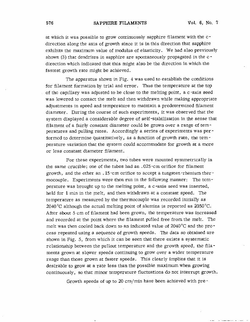
The apparatus shown in Fig. 4 was used to establish the conditions for filament formation by tr ial and e r ror . Thus the temperature at the top of the capillary was adjusted to be close to the melting point, a c -axis seed was lowered to contact the melt and then withdrawn while making appropriate adjustments in speed and temperature to maintain a predetermined filament diameter. During the course of such experiments, it was observed that the system displayed a considerable degree of self -stabilization in the sense that filament of a fairly constant diameter could be grown over a range of tem- peratures and pulling rates. Accordingly a series of experiments was per - formed to determine quantitatively, as a function of growth rate, the tem- perature variation that the system could accommodate for growth at a more o r less constant diameter filament.
For these experiments, two tubes were mounted symmetrically in the same crucible; one of the tubes had an .025-cm orifice for filament growth, and the other an . 15 -cm orifice to accept a tungsten-rhenium ther - mocouple. Experiments were then run in the following manner: The tem- perature was brought up to the melting point, a c -axis seed was inserted, held for 1 min in the melt, and then withdrawn at a constant speed. The temperature a s measured by the thermocouple was recorded initially a s 2040°C although the actual melting point of alumina is reported a s 2050°C. After about 5 cm of filament had been grown, the temperature was increased and recorded at the point where the filament pulled free from the melt. The melt was then cooled back down to an indicated value of 2040°C and the pro- cess repeated using a sequence of growth speeds. The data so obtained a re shown in Fig. 5, from which it can be seen that there exists a systematic relationship between the pullout temperature and the growth speed, the fila- ments grown at slower speeds continuing to grow over a wider temperature range than those grown at faster speeds. This clearly implies that it is
desirable to grow at a rate less than the possible maximum when growing continuously, so that minor temperature fluctuations do not interrupt growth.
Growth speeds of up to 20 cm/min have been achieved with pre-
Vol. 6, No. 7 SAPPHIRE FILAM&NTS
GROWTH SPEED ( c m h ~ n 1
FIG. 5 Dependence of pullout temperature on growth speed for
,025 -cm -diameter filament
chosen filament diameters in the range .0 1 - .05 cm; however, good diameter control over a long period required that the ra te be 2.5 - 5 crn/rnin. Al- though most of our work involved growth in the c-direction, we have been able to grow continuous sapphire filaments in essentially any crystallo - graphic direction SQ long a s the rate of growth is kept to about 2.5 cm/min o r lower. At faster speeds where dendritic growth is apparently occurring, the c -axis is the preferred one for continuous filament propagation. This, a s we noted above, is the major dendritic direction for sapphire. In Fig. 6, an example of a c -axis sapphire filament is shown; Laue back -reflection analysis of the filament shows it to be a single crystal with a small number of low angle grain boundaries. Filaments such a s this exhibit average
tensile strengths greater than 300,000 psi (using a 2.5 -cm gauge length, and 6 a strain rate of .005 min-' ) and a modulus of elasticity 67.5 x 10 psi. (7)
Using the die designs shown in Fig. 3(a) and 3(b), sapphire tubes and ribbons have been grown respectively. 111 all cases, the precise ehape of the growing crystal i s determined by the shape of the liquid reservoir formed at the top of the die. Tubes of typically a 1 cm outside diameter and an .075 -cm wall thickness have been grown at rates up ta 3.5 cm/min; ribbons up to 2 .5 cm wide and typically ,075-cm thickness have been grown at similar riites.
These results indicated that the use of a capillary feed arrangement

5 '38 SAPPHIRE FILAMENTS Vol. 6 , No. 7
FIG. 6 Photograph of sapphire filament
t o maintain a constant liquid level for growth itldepelldeilt of the liquid level
in the crucible and to control the shape and size of the growing crystal lends
itself also to the growth of several sapphire crystals simultalleously. We
have experimeiltally confirmed this progi~ostication by growing three fila-
ments simultaileously from a single crucible using three capillary as sem-
bl ies placed radially symmetrically and using three separate seeds mounted
on a cornmoil pulling shaft.
In Part I1 of this se r i e s , at1 improved version of this crystal growth
technique i s described which extends the process to the growth of virtually
any chosen c ross -sectional shape from the melt.
Ackilow ledrrments
The authors a r e pleased to acknowledge useful discussioils and e x - perimental assistallce from a number of their colleagues, with special thanks
Vol. 6 , No. 7 SAPPHIRE FILAMENTS 5 79
due to Mr. John Bailey and Mr. William Little who aided in the exper imei~ts , and to Dr . George Hurley who made mechanical measuremeilts on the crys ta ls .
This work was supparted by the U. S. Air Force Materials Labora- tory , Nonmetallic Materials Division (development of basic techniques), and Manufacturing Technology Division (continuous filament growth equipment), Wright -Patterson Air Force Base, Dayton, Ohio.
References ,--
1. E . vo11 Gomperz, Z. Pl~ysik. - I$, 184 (1922).
2. G. K. Gaule and J . R. Pastore, in Metallurgy of Elemei~ta l and Corn - pound Semiconductors , p. 20 1 lnterseience Publighers , New Y ork and Loridon, (1960).
3. H. E . LaBelle, J r . , akd A . I. Mlavsky, Nature 216, 5115 (1967), 574.
-
4. A . I. Mlavsky and H. E . LaBelle, Jr. , in Whisker Technology, p. 121, Albert P. Levitt, Ed. , John Wiley & Soils, Inc. (1970).
5. H. E . LaBelle, Jr. , Growth of Inorganic Filaments, U. S. Patent No. 3,471,266.
6. J . J . Rasmussen, et a l , Status Report to Office of Naval Research, Contract No. N0014-67 -C -0341, NR032 -501.
7. H. E . LaBelle, J r . , and G. F. Hurley, Sampe Journal - 6, 17 (1970).


Mat. Res. Bull. Vol. 6, pp. 581-590, 1971. Pergamon Press, Inc. Printed in the United States.
GROWTH OF CONTROLLED PROFILE CRYSTALS FROM THE MELT: PART I1 - EDGE -DEFINED,
FILM -FED GROWTH (EFG)
H, E. LaBelle, Jr. Tyco Laboratories, 111~.
Waltham, Massachusetts 02154
(Received May 27, 1971; Communicated by J. B. Goodenough)
ABSTRACT
A crystal growth technique i s described, "Edge -Defined, Film -Fed Growth" (EFG), by which continuous single crystals having virtually any cross -sectional shape can be grown from the melt. Crystals with shapes ranging from simple rods or filaments to almost arbitrarily com- plex cross sections may be grown with excellent dimen- sional control over very long lengths with minimal tem- perature and speed control. The EFG technique i s an extension of that described in "Growth of Controlled Pro- file Crystals from the Melt: Part I"* in that a capillary structure i s used to furnish a constant liquid level at the growth interface a s melt in the crucible i s depleted. In the present technique, however, the shape of the growing crystal i s determined by a thin melt layer sandwiched between the growing solid liquid interface and the plane top surface of the rigid capillary structure. The crystal grows only over solid regions of the die surface and not over any deep depressions in this surface. Accordingly any pattern of depressions fabricated into the top surface of the die will be propagated in the growing crystal. I11 this paper the application of the process to the growth of various single crystal sapphire shapes directly from the melt is described.
Process Descr i~t ion
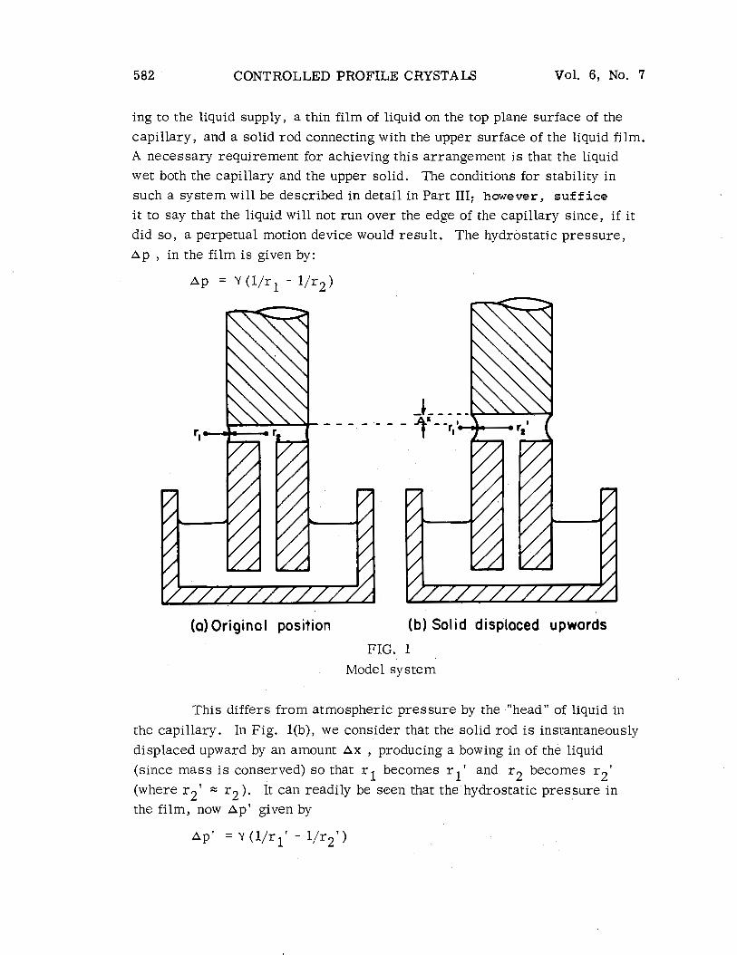
In Fig. l(a), a system i s shown comprising a supply of liquid in a container, a solid capillary tube mounted vertically in the liquid and connect -
9;
"Growth of Controlled Profile Crystals from the Melt, " Parts I, 11, 111, and IV will be published in this Journal.
58 1
582 CONTROLLED PROFILE CRYSTALS Vol. 6, No. 7
ing to the liquid supply, a thin film of liquid on the top plane surface of the
capillary, and a solid rod connecting with the upper surface of the liquid film. A necessary requirement for achieving this arrangement i s that the liquid
wet both the capillary and the upper solid. The conditions for stability in such a system will be described in detail in Part 111; however, suffice
i t to say that the liquid will not run over the edge of the capillary since, if it
did so , a perpetual motion device would result . The hydrostatic pressure , Ap , in the film is given by:
(a) Original position (b) Solid displaced upwords
FIG. 1
Model system
This differs from atmospheric pressure by the "head" of liquid in
the capillary. I11 Fig. l(b), we consider that the solid rod i s instantaneously displaced upward by an amount Ax , producing a bowing in of the liquid (since mass is conserved) s o that r l becomes r l ' and r2 becomes r 2 '
(where r2' = r2 ). It can readily be seen that the hydrostatic pressure in the film, now Ap' given by
Vol. 6, No. 7 CONTROLLED PROFILE CRYSTALS 583
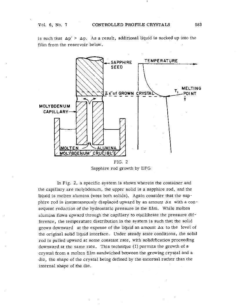
i s such that Dpf > Ap. As a result, additional liquid i s sucked up into the film from the reservoir below.
- SAPPHIRE SEED
X x'of GROWN - - - - - -
TEMPERATURE
FIG. 2 Sapphire rod growth by EFG
In Fig. 2, a specific system i s show11 wherein the container and the capillary a r e molybdenum, the upper solid i s a sapphire rod, and the liquid i s molten alumii~a (wets both solids). Again consider that the sap- phire rod i s iilstailtaileously displaced upward by an amouqt Ax with a con- sequent reduction of the hydrostatic pressure in the film. While molten
alumina flows upward through the capillary to equilibrate the pressure dif - ference, the temperature distribution ill the system i s such thgt the solid grows dowiiward at the expense of the liquid an amount Ax to the level of the original solid liquid interface. Under steady state condif ions, the solid rod i s pulled upward a t some constaiqt rate, with solidificatioll proceeding downward at the same rate. This technique (1) permits the growth of a
crystal from a molten film sandwiched between the growing crystal and a die, the shape of the crystal being defined by the external rather than the internal shape of the die.
CONTROLLED PROFILE CRYSTALS Vol. 6, No. 7
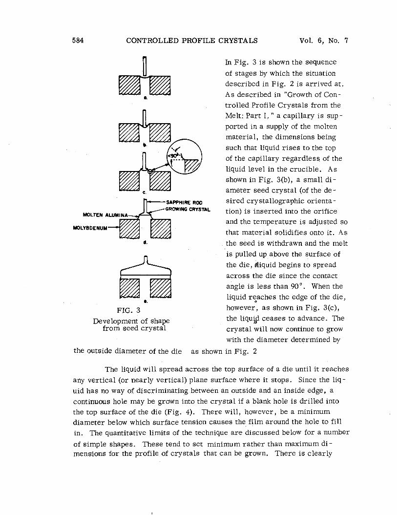
n In Fig. 3 i s shown the sequence
of stages by which the situation described in Fig. 2 i s arrived at.
As described in "Growth of Con- trolled Profile Crystals from the Melt: Part I , " a capillary i s sup-
ported in a supply of the molten
n material, the dimensions being
'. A/ \ such that liquid r ises to the top of the capillary regardless of the
liquid level in the crucible. As shown in Fig. 3(b), a small di- ameter seed crystal (of the de-
SAPPHIRE ROO sired crystallographic orienta -
MOLTEN ALUMINA GRoWING CRYSTAL tion) i s inserted into the orifice
MOLYBDENUM a @ and the temperature is adjusted so
that material solidifies oilto it. As d. the seed is withdrawn and the melt
is pulled up above the surface of
the die, @liquid begins to spread
FIG. 3 Development of shape
from seed crystal
across the die since the contact
angle i s less than 90". When the
liquid reaches the edge of the die,
however, a s shown in Fig. 3(c), the liquid ceases to advance. The
crystal will now continue to grow with the diameter determined by
the outside diameter of the die a s shown in Fig. 2
The liquid will spread across the top surface of a die until it reaches
any vertical (or nearly vertical) plane surface where it stops. Since the liq-
uid has no way of discriminating between a11 outside and an inside edge, a
continuous hole may be grown into the crystal if a blank hole i s drilled into
the top surface of the die (Fig. 4). There will, however, be a minimum diameter below which surface tension causes the film around the hole to fill in. The quantitative limits of the technique a re discussed below for a number
of simple shapes. These tend to set minimum rather than maximum di- mensions for the profile of crystals that can be grown. There i s clearly

Vol. 6, No. 7 CONTROLLED PROFILE CRYSTALS
no limit to the complexity of the pro-
file (see for example, Fig. s), but only to the smallest radii of curva-
ture that form part of the pattern Fur - ther by reference to the discussion accompanying Fig. 3 , it can readily be seen that crystals of arbitrary com- plexity can be grown using the simplest
seed geometry, namely a small diam-
eter rod.
FIG. 4 Rod with continuous
eccentric hole
B- SAPPHI RE
,MOLTEN ALUMINA
-MOLYBDENUM
SAPPHIRE
MOLTEN ALUMINA
MOLYBDENUM
FIG. 5 Complex shapes
Since the shape of the growing crystal is defined by the edge of a die and growth takes place from a film of liquid which i s continuously r e - plenished, the denotative name "edge -defined, film-fed growth"(EFG)* has
-~ ~ - -
* Name suggested by A. I. Mlavsky.

586 CONTROLLED PROFILE CRYSTALS Vol. 6, No. %
been given to the technique. The process i s described here in qualitative
terms; a more detailed basic theory of the process including a discussion
of the limits of stability of the system will be presented in Part 111 of this ser ies .
The apparatus used for EFG is essentially a modified Czochralski unit a s previously described in Part I of this series. The majority of all sapphire crystals has been grown from a molybdenum crucible in an argon
atmosphere. Alternates such a s tungsten and iridium crucibles and a helium atmosphere may also be used.
FIG. 6
Experimental Results
In a typical experiment, a molybdenum crucible i s provided with a molybdenum die of a chosen configuration, charged with small par- ticles of a -alumina and heated by means of R F in the equipment previously described. An approximate estimate of the correct conditions for growth i s afforded by observation of molten alumina rising to the top of the capillary orifices
within the die. A small diameter preoriented sapphire seed is lowered to contact the melt in
one of the orifices. The seed i s then moved up- wards, and the speed and/or temperature a r e ad- justed so that the liquid spreads out across the
surface of the die to form the complete profile
that it i s intended to grow. I11 practice, the de -
Development of tube sired cross -sectional shape is achieved within
from rod seed 2 - 5 cm of growth as shown in Fig. 6.
Using EFG by the method indicated above, sapphire filaments,
ribbons, and tubes a r e being grown. In Fig. 7 , a variety of sapphire
shapes i s shown. In Table 1, the maximum and minimum sizes grown in various simple shapes is summarized. Filaments have been grown in
lengths up to several hundreds of feet since they a re flexible and readily lend themselves to contiiluous collection on a spooling mechanism; inflex-
ible shapes such a s tubes have been grown in lengths up to 5 feet. For accurate control of diameter, the maximum growth rate for filaments,

Vol. 6, No. 7 CONTR.OLLED PROFILE CRYSTALS
TABLE 1
Sapphire Shapes Produced
Lellgt h Dimei~sions Shape (maximum, cm) (maximum, cm) (minimum, cm)
Filament 11,500 . 5 diameter . 0 13 diameter
Tube
150 2 .5 wide 1 wide . 15 thick .008 thick
FIG. 7
Sapphire shapes produced directly from the melt by EFG.

588 CONTROLLED PROFILE CRYSTALS Mol. 6, No, 7
typically .025 -cm diameter is 5 cm/min. As the cross section gets
larger, this rate is reduced; for example, the maximum rate of growth
for a tube 4.. 0 -cm o. d , x .075 -cm wall thickness i s approximately
2 cm/min. It is clear that, to grow filaments several hundred feet in
length, growth must be continuous over periods of days. The self-stabil-
izing features of the technique which make it possible to achieve growth from the melt over such very long periods without the necessity for accu- rate temperature control a re described in detail in Part I11 of this series.
The micromorphology of sapphire produced by this technique will be discussed in detail in Part IV of this series. Briefly, the micromor-
phology consists of an array of microvoids which vary in size and nunlber
depending on the actual growth col~ditions. Fig. 8 shows two filament
c ross sections viewed under transmitted light. The filament shown in
Fig. 8(a) was grown at 5 cm/min while that shown in Fig. 8(b) was grown
at 1.3 cm/min. This type of microvoid distribution i s observed in all
sapphire filaments grown at relatively fast speeds by EFG, with the spe - cific exception of totally clear filament (2) grown under certain conditions
to be described in Part 111.
FIG. 8
Filament cross sections showing distribution of microvoids

Vol. 6, No. 7 CONTROLLED PROFILE CRYSTALS
Although the majority of experiments have beell performed on
sapphire, several other materials including MgA1204, NaC1, Cu -Au alloys, andLiNb03 (3) have been grown. I11 general, the process i s
applicable to any material for which a nonreactive die material which i s wet by the liquid can be found. An essentially iqfinite variety of cross - sectional shapes may be grown, in some cases of a complexity impos- sible to fabricate by conventional methods.
Acknow ledgments
The author wishes to thapk Dr. A. I. Mlavsky for his invaluable technical guidance and stimulation, Drs. G. I?. Hurley and J . T . A.
Pollack for their technical contributions, Messrs. J . Bailey, C . Cronan and W. Little for their experimental expertise, and Dr. G. A. Wolff for his helpful technical discussions.
This work was supported by the U. S. Air Force Materials Lab- oratory, Nonmetallic Materials Division, Wright-Patterson Air Force Base, Dayton, Ohio.
References
1. H. E. LaBelle, Jr. , Method and Apparatus for Growing Crystalline Materials, British Patent No. 1,205,544.
2. To be published by J T.A .Pollock, Tyco Laboratories, Inc.
3. Final Report on Army Contract No. DAAB07 -69 € -0 138.