development of plate heat exchangers as main components of
TRANSCRIPT

ISRN LUTMDN/TMHP—11/5234—SE
Kkk ISSN 0282-1990
Development of Plate Heat Exchangers as Main Components of an Absorption Chiller
Thomas Hasenöhrl
Thesis for the Degree of Master of Science
Division of Heat Transfer Division 1: Technology for
Department of Energy Sciences Energy Systems and
Faculty of Engineering, LTH Renewable Energy
Lund University Bavarian Center for Applied
P.O. Box 118 Energy Research e.V.
SE-221 00 Lund Walther-Meißner-Str. 6
Sweden 85748 Garching
Germany

Abstract
Absorption chillers are energy saving, but low-capacity applications are not availableyet. To become competitive with the established vapor-compression chillers, compactand inexpensive main component heat exchangers are required. In the respective ca-pacity range, the conventionally used tube bundle heat exchangers can hardly fulfill thatrequirement - plate heat exchangers, however, could. The present work evaluates cy-cle and heat exchanger concepts for a four kilowatt lithium-bromide absorption chillerbased on compact plate heat exchangers. The preliminarily planned external tempera-tures are 15/10◦C, 30/38◦C and 90/80◦C.Cycle calculations show: Recirculation provides enough solution to permit good wettingof the absorber. Two concepts perform similarly. At the generator, recirculation requiresan additional pump. Alternatively, the generator could operate as a pool-generator, butonly if the external temperatures are adopted. Making evaporator/absorber and con-denser/generator pairwise equal in size results in a low overall heat exchanger area in-crease. Consequently, two heat exchangers can be pressed on one plate, which lowersthe cost and allows to make the chiller more compact.CFD-simulations of different plate heat exchangers show: Lowering the plate width,which is favorable as to vapor pressure loss, hardly impacts the water side. Rotat-ing the channels towards the horizontal promises better wetting on the solution side,but increases the pressure loss on the water side. Smaller channels between the waterchannels supposedly increase wetting, too. Moreover, they increase the heat exchangeperformance and reduce the pressure loss on the water side.Integrating the wall of the pressure vessel and the solution distribution system into theheat exchanger plates is an approach to further reduce the manufacturing costs and sizeof the absorption chiller.
i
Contents
1 Introduction 11.1 Background: The Need for a Sustainable Energy Supply . . . . . . . . 11.2 Market Gap for Low-scale Absorption Chillers . . . . . . . . . . . . . 21.3 Motivation and Structure of this work . . . . . . . . . . . . . . . . . . 3
2 Fundamentals of Absorption Chilling 42.1 Vapor-Compression Chiller . . . . . . . . . . . . . . . . . . . . . . . . 42.2 Absorption Chiller . . . . . . . . . . . . . . . . . . . . . . . . . . . . 5
3 Heat Exchangers for Absorption Chillers 93.1 Disadvantages of Small Tube Bundle Heat Exchangers . . . . . . . . . 93.2 Plate Heat Exchangers for Absorption Chillers . . . . . . . . . . . . . . 103.3 Advanced Plate Design: Integration . . . . . . . . . . . . . . . . . . . 12
3.3.1 Integrating the Fluid Distribution System . . . . . . . . . . . . 123.3.2 Integrating the Vacuum Vessel . . . . . . . . . . . . . . . . . . 123.3.3 Integrating Two Heat Exchangers on One Plate . . . . . . . . . 13
4 Modeling of Absorption Chiller Cycle Concepts 154.1 Modeling of Absorber Recirculation . . . . . . . . . . . . . . . . . . . 17
4.1.1 Motivation for Absorber Recirculation . . . . . . . . . . . . . . 174.1.2 Modeled Recirculation Concepts . . . . . . . . . . . . . . . . . 184.1.3 Results of the Absorber Recirculation Cycle Calculations . . . . 19
4.2 Equal Heat Exchanger Sizes . . . . . . . . . . . . . . . . . . . . . . . 234.3 Pool Generator . . . . . . . . . . . . . . . . . . . . . . . . . . . . . . 26
4.3.1 Concept, Motivation and Constraints of a Pool Generator . . . . 264.3.2 How to Model a Pool Generator . . . . . . . . . . . . . . . . . 284.3.3 Convective Heat Transfer Coefficient in the Pool . . . . . . . . 294.3.4 Results of the Pool Generator Calculations . . . . . . . . . . . 32
5 CFD-based Heat Exchanger Design 355.1 Design Goals for the New Heat Exchanger . . . . . . . . . . . . . . . . 355.2 Modification of the Heat Exchanger Design . . . . . . . . . . . . . . . 385.3 CFD-Simulation as Evaluation Tool . . . . . . . . . . . . . . . . . . . 405.4 Investigated Heat Exchanger Designs . . . . . . . . . . . . . . . . . . 415.5 CFD-Simulation . . . . . . . . . . . . . . . . . . . . . . . . . . . . . . 45
5.5.1 Determination of the Water Mass Flow Rate . . . . . . . . . . . 455.5.2 Simulation Results . . . . . . . . . . . . . . . . . . . . . . . . 485.5.3 Conclusions from the Simulation Results . . . . . . . . . . . . 52
6 Summary 54
References 56
A Solution Mass Flow Rate for Good Wetting 60

ii
List of Figures
2.1 Schematic of a vapor-compression chiller . . . . . . . . . . . . . . . . 42.2 Schematic of a single-effect absorption chiller . . . . . . . . . . . . . . 62.3 Single-effect absorption cycle in a Dühring-plot . . . . . . . . . . . . . 83.1 Heat exchangers used as absorbers . . . . . . . . . . . . . . . . . . . . 93.2 Plate heat exchanger . . . . . . . . . . . . . . . . . . . . . . . . . . . 113.3 Two-in-one heat exchanger plate . . . . . . . . . . . . . . . . . . . . . 144.1 Specific absorber solution mass flow rate over f, basic cycle . . . . . . . 184.2 Modeled concepts for solution recirculation at the absorber . . . . . . . 194.3 Overall area optimized calculation of cycle concepts . . . . . . . . . . 204.4 Absorber heat exchanger area and recirculation ratio for absorption cy-
cles with solution recirculation at the absorber . . . . . . . . . . . . . . 214.5 Overall heat exchanger areas for different cycle and area optimization
concepts . . . . . . . . . . . . . . . . . . . . . . . . . . . . . . . . . . 244.6 Overall heat exchanger area and COP for the sump recirculation concept 254.7 Equilibrium temperature of LiBr solution in a pool . . . . . . . . . . . 274.8 Discretization of the flooded part in the pool generator . . . . . . . . . 284.9 Heat transfer coefficients measured by [Lee et al. (1991)] . . . . . . . . 304.10 Atotal of an absorption chiller with pool generator and absorber sump
recirculation . . . . . . . . . . . . . . . . . . . . . . . . . . . . . . . . 335.1 The plate heat exchanger investigated by Hulin and Behr . . . . . . . . 355.2 Dühring-plot with two different equilibrium states at x = 55% . . . . . . 365.3 Heat exchanger plate hb . . . . . . . . . . . . . . . . . . . . . . . . . . 385.4 Isometric view of the simulated 2sub plate package . . . . . . . . . . . 415.5 Flow trajectory plot of the 2sub plate package . . . . . . . . . . . . . . 425.6 Heat exchanger plate nosub63 . . . . . . . . . . . . . . . . . . . . . . 435.7 Heat exchanger plate nosub . . . . . . . . . . . . . . . . . . . . . . . . 445.8 Heat exchanger plate 1sub . . . . . . . . . . . . . . . . . . . . . . . . 445.9 Heat exchanger plate 2sub . . . . . . . . . . . . . . . . . . . . . . . . 445.10 The overall heat transfer coefficient U as a function of the convective
heat transfer coefficient on the water side . . . . . . . . . . . . . . . . 475.11 Prestudy to find the appropriate cooling water mass flow rate . . . . . . 475.12 Averaged convective heat transfer coefficients on the water side . . . . . 485.13 Temperature plot of the film side of the hb plate . . . . . . . . . . . . . 505.14 Temperature plot of the film side of the nosub63 plate . . . . . . . . . . 505.15 Temperature plot of the film side of the nosub plate . . . . . . . . . . . 505.16 Temperature plot of the film side of the 1sub plate . . . . . . . . . . . . 515.17 Temperature plot of the film side of the 2sub plate . . . . . . . . . . . . 515.18 Specific capacity and pressure loss of the simulated heat exchanger plates 52
List of Tables
4.1 Planned external temperatures . . . . . . . . . . . . . . . . . . . . . . 155.1 Main characteristics of the simulated heat exchanger plates . . . . . . . 45
iii
Symbols
Latin characters
Symbol Unit Meaning
A m2 area
cpkJ
kg·K specific heat capacity
C W heat capacity rate
COP − coefficient of performance
f − solution circulation ratio
fR − solution recirculation ratio
h Wm2K
heat transfer coefficient
h m height
k Wm·K thermal conductivity
lmtd K log mean temperature difference
m kgs
mass flow rate
mspeckgm2s
specific mass flow rate
n − integer number of heat exchanger plate pairs
p bar pressure
q Wm2 heat transfer rate
Q W heat flow rate
s m thickness
t ◦C temperature
T K temperature
U Wm2K
overall heat transfer coefficient
v m3
kgspecific volume
V̇ ls
volume flow rate
W W mechanical work
x − solution concentration (mass share of ab-sorbent)

iv
Greek characters
Symbol Unit Meaning
∆p mbar pressure loss
∆t K temperature spread
η − ratio of component performance and coolingperformance
ρ kgl
density
Subscripts
Subscript Meaning
0 referring to the evaporator (pressure or temperature level)
1 referring to the condenser/absorber (pressure or temperaturelevel)
2 referring to the generator (pressure or temperature level)
a outlet
abs absorber
c cooling water
con condenser
e external
evap evaporator
f film (i.e., falling film)
flooded referring to the flooded part of the generator
gen generator
i inner / internal
i inlet
i index for discretization
min minimum
mix mixed solution

v
mixed referring to the mixed recirculation concept
o outer
package referring to one plate package
p plate
pool for pool boiling
recirc recirculated
refr refrigerant
rich rich solution (high water content)
sat saturation
sol solution
sump referring to the sump recirculation concept
total all heat exchangers
w wetted
Abbreviations
Subscript Meaning
CAD Computer-Aided Design
CFD Computational Fluid Dynamics
EES Engineering Equation Solver (Software for numerical solu-tion of equation systems)
HW hot water
LiBr lithium-bromide
OECD Organization for Economic Cooperation and Development
ZAE Bayern Bayerisches Zentrum für Angewandte Energieforschung -Bavarian Center for Applied Energy Research

1 Introduction
One reliable source of energy is not even close to being depleted: Simplysaving it may be the safest and cleanest option mankind has.[Jung (2007)]
1.1 Background: The Need for a Sustainable Energy Supply
To be exact, saving energy is not a source of energy. In fact, coal, gas, uranium andso on are not either - they are rather energy storages, containing energy in a chemicalform. And, according to the First Law of Thermodynamics, this chemical energy canbe transformed into other forms of energy, for example thermal, mechanical, or electri-cal energy. But energy can neither be created nor destroyed. For a long time, naturalenergy resources were considered virtually inexhaustible. Maybe this is why the ex-pression energy source could establish in everyday and scientific language. Everybodyuses terms like energy consumption, energy conservation and energy wastage - althoughthey are physically incorrect - because there is a general consensus on the meaning ofthese terms.Today, it is considered as a matter of fact that natural resources are finite, yet the grow-ing world population and increasing consumption of goods and energy require more andmore natural resources. This year, the world population reaches seven billion1 and in2030, more than eight billion people will live on earth. The OECD2 estimates that inthe meantime, the world energy consumption will rise by more than fifty percent andthe electricity consumption will double [Bethge & Wüst (2007)]. It is only a matter oftime until the increased thirst for energy will result in the depletion of the fossil energyresources. If then, however, our civilization still depends on these resources in the wayit does today, international conflicts are more than probable. Moreover, the rising con-sumption of fossil fuels is connected with environmental problems and climate change.
Shortly, the current situation and future prospects demand for a reduced consumptionof fossil fuels and, more general, a sustainable energy supply. In Germany and otherEuropean countries, the most frequently discussed approach for a sustainable energysupply is a massive extension of the renewable energies. Increasing the renewable en-ergies’ share of the overall energy supply, however, is easier and faster to achieve if theoverall energy consumption is lower. Insofar, [Jung (2007)] is right when he states thatsaving energy is an energy source. Saving energy helps to achieve a sustainable energysupply because it reduces the number of wind turbines, biogas plants, solar panels, andso on, that need to be installed to replace the conventional power and heat facilities withsustainable alternatives.
1[Kommer & Hinz (2010)]2Organization for Economic Cooperation and Development
1 Introduction 2
1.2 Market Gap for Low-scale Absorption Chillers
One sector in which considerable amounts of power can be saved is air conditioning.In Germany, air conditioning in the residential sector is not established yet. It is mostlybusiness and office premises that are equipped with air conditioning. In other countries,however, air conditioning plays a more important roll [Clausen (2007)]. In the UnitedStates, for example, virtually all buildings are air conditioned - including residentialbuildings. Unsurprisingly, this also reflects in the country’s power consumption: Morethan ten percent of the power consumed in the United States is used for air conditioning.On hot days, that share may rise up to more than twenty percent [Höges (1997)]. World-wide, the market for air conditioners is growing. Hence, also the energy consumed forair conditioning increases [Clausen (2007)].Currently, most air conditioning systems with medium capacity and all air condition-ers with low capacity are based on the vapor-compression technology. These vapor-compression chillers are usually driven by an electric compressor and consume a con-siderable amount of electric power, the most valuable form of energy. There is, however,another technology for chill production whose driving energy is not electric power butheat: absorption chilling. Depending on their design, absorption chillers can use differ-ent heat sources, for instance district heat, reject heat or solar heated water - heat that iseither abundant or can be produced in an inexpensive and ecologically sustainable way.Estimations for the primary energy saving by absorption chillers are as high as 40 to60 percent [Clausen (2007)]. That makes absorption chillers a promising alternative tovapor-compression chillers.
All the same, private customers cannot buy absorption chillers. Most absorptionchillers on the market have capacities of hundred kilowatts and more - far too muchfor chilling an apartment or a single-family home. In fact, there is no absorption chillerin the capacity range that is relevant for the residential sector, that is, below ten kilo-watts. The reason for that market gap is of technical and economical nature:The main components of an absorption chiller are heat exchangers. In conventional ab-sorption chillers with capacities of hundred kilowatts and more, these heat exchangersare tube bundle heat exchangers. As for other technologies, downscaling tube bundleheat exchangers does only work to a certain extent. The relative size, weight, materialcost and labor cost for the tube bundle heat exchangers increase. Consequently, a chillerwith low capacity, having small tube bundle heat exchangers, becomes large, heavyand expensive compared to its capacity and, above all, compared to vapor-compressionchillers with the same capacity. For absorption chillers with low capacities, tube bundleheat exchangers are therefore not the right technology [Estiot (2009)].

1 Introduction 3
1.3 Motivation and Structure of this work
Some years ago, the ZAE Bayern3 started to research on alternative heat exchangertechnologies for low-scale absorption chillers. The goal of this research is to developa compact and inexpensive heat exchanger that allows to design low-scale absorptionchillers able to establish on the market, which is dominated by the conventional vapor-compression chillers. During that research, plate heat exchangers turned out to be apromising approach. The first prototype, however, did not perform as expected, mainlybecause of poor wetting with solution.Last year, the ZAE Bayern launched a project that aims at the development of a low-capacity absorption chiller with compact plate heat exchangers. The first and centraltask is to improve the plate heat exchanger design. Good wetting, a compact geometryand a low first cost are the aspired qualities of the new plate heat exchanger.The previous work on the project has brought about a number of ideas for how to changethe heat exchanger and cycle design in order to attain these qualities. However, some ofthese ideas need to be investigated more deeply to make sure that the respective designchanges in fact have a positive impact. This investigation is provided by the presentwork:
First, chapter 2 introduces some fundamental knowledge on vapor-compression chill-ers and absorption chillers. Then, chapter 3 briefly discusses the use of tube bundle andplate heat exchangers in absorption chillers and presents the integration design conceptas an approach to create a compact, low-cost plate heat exchanger. The cycle calcu-lations in chapter 4 and the flow simulations in chapter 5 evaluate the different ideasfor design changes. Lastly, chapter 6 summarizes the most important findings and theirconsequences for the heat exchanger and cycle design.
3Bayerisches Zentrum für Angewandte Energieforschung - Bavarian Center for Applied Energy Re-search
2 Fundamentals of Absorption Chilling
This chapter introduces some fundamentals that are helpful for the reader who is notfamiliar with the topic absorption chilling. More comprehensive information is availablein the referenced literature.
2.1 Vapor-Compression Chiller
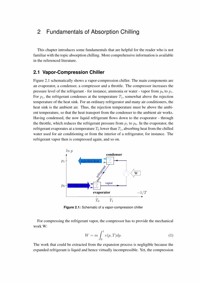
Figure 2.1 schematically shows a vapor-compression chiller. The main components arean evaporator, a condenser, a compressor and a throttle. The compressor increases thepressure level of the refrigerant - for instance, ammonia or water - vapor from p0 to p1.For p1, the refrigerant condenses at the temperature T1, somewhat above the rejectiontemperature of the heat sink. For an ordinary refrigerator and many air conditioners, theheat sink is the ambient air. Thus, the rejection temperature must be above the ambi-ent temperature, so that the heat transport from the condenser to the ambient air works.Having condensed, the now liquid refrigerant flows down to the evaporator - throughthe throttle, which reduces the refrigerant pressure from p1 to p0. In the evaporator, therefrigerant evaporates at a temperature T0 lower than T1, absorbing heat from the chilledwater used for air conditioning or from the interior of a refrigerator, for instance. Therefrigerant vapor then is compressed again, and so on.
vaporcooling energy
rejection heat
−1/T
ln p
T0 T1
p0
p1
condenser
evaporator
refri
gera
nt
W
Figure 2.1: Schematic of a vapor-compression chiller
For compressing the refrigerant vapor, the compressor has to provide the mechanicalwork W:
W = m
∫ 1
0
v(p, T )dp. (1)
The work that could be extracted from the expansion process is negligible because theexpanded refrigerant is liquid and hence virtually incompressible. Yet, the compression
2 Fundamentals of Absorption Chilling 5
work W is not negligible. Usually, and particularly in refrigerators and in small scaleair conditioning applications, the compressor is driven by an electric motor. Conse-quently, these vapor-compression chillers consume a significant amount of electricity([Alefeld & Radermacher (1993)], [Herold et al. (1996)]).
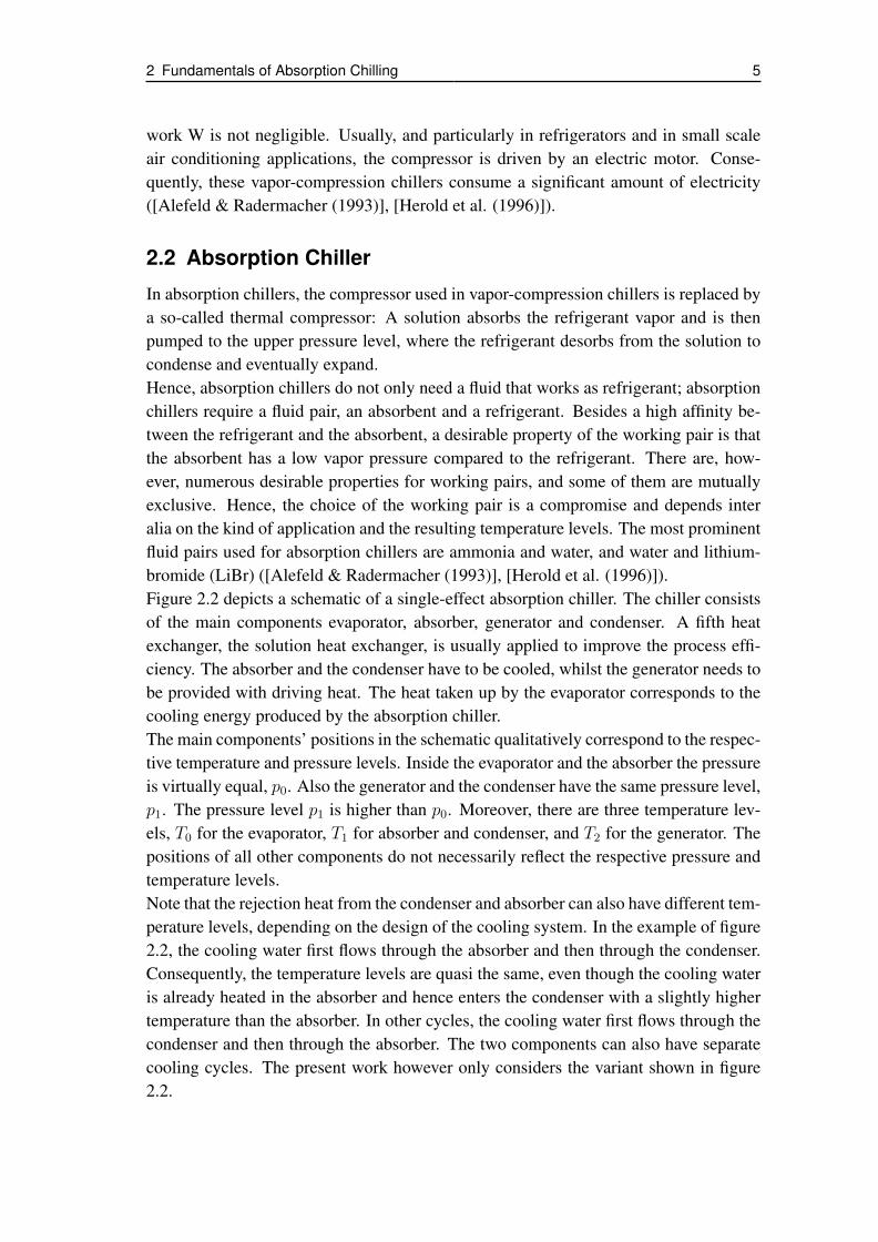
2.2 Absorption Chiller
In absorption chillers, the compressor used in vapor-compression chillers is replaced bya so-called thermal compressor: A solution absorbs the refrigerant vapor and is thenpumped to the upper pressure level, where the refrigerant desorbs from the solution tocondense and eventually expand.Hence, absorption chillers do not only need a fluid that works as refrigerant; absorptionchillers require a fluid pair, an absorbent and a refrigerant. Besides a high affinity be-tween the refrigerant and the absorbent, a desirable property of the working pair is thatthe absorbent has a low vapor pressure compared to the refrigerant. There are, how-ever, numerous desirable properties for working pairs, and some of them are mutuallyexclusive. Hence, the choice of the working pair is a compromise and depends interalia on the kind of application and the resulting temperature levels. The most prominentfluid pairs used for absorption chillers are ammonia and water, and water and lithium-bromide (LiBr) ([Alefeld & Radermacher (1993)], [Herold et al. (1996)]).Figure 2.2 depicts a schematic of a single-effect absorption chiller. The chiller consistsof the main components evaporator, absorber, generator and condenser. A fifth heatexchanger, the solution heat exchanger, is usually applied to improve the process effi-ciency. The absorber and the condenser have to be cooled, whilst the generator needs tobe provided with driving heat. The heat taken up by the evaporator corresponds to thecooling energy produced by the absorption chiller.The main components’ positions in the schematic qualitatively correspond to the respec-tive temperature and pressure levels. Inside the evaporator and the absorber the pressureis virtually equal, p0. Also the generator and the condenser have the same pressure level,p1. The pressure level p1 is higher than p0. Moreover, there are three temperature lev-els, T0 for the evaporator, T1 for absorber and condenser, and T2 for the generator. Thepositions of all other components do not necessarily reflect the respective pressure andtemperature levels.Note that the rejection heat from the condenser and absorber can also have different tem-perature levels, depending on the design of the cooling system. In the example of figure2.2, the cooling water first flows through the absorber and then through the condenser.Consequently, the temperature levels are quasi the same, even though the cooling wateris already heated in the absorber and hence enters the condenser with a slightly highertemperature than the absorber. In other cycles, the cooling water first flows through thecondenser and then through the absorber. The two components can also have separatecooling cycles. The present work however only considers the variant shown in figure2.2.

2 Fundamentals of Absorption Chilling 6
vapor
vapor
hot water
rejection heatcooling energy
driving heatrejection heat
−1/T
ln p
T0 T1 T2
p0
p1
desorbercondenser
absorberevaporator
solution heat exchanger
cool
ing
wat
er
chilled waterre
frige
rant
rich
solu
tion
poor
solu
tion
Figure 2.2: Schematic of a single-effect absorption chiller (adopted from [Estiot (2009)])
Briefly, the function of the absorption cycle can be described as follows: In the evap-orator, the refrigerant, coming from the condenser, evaporates at the pressure level p0.As p0 is low, the refrigerant evaporates at a low temperature level, T0. The chilled waterloop provides the necessary heat. The refrigerant vapor produced in the evaporator thenflows to the absorber, where it is absorbed by a liquid film of poor working solution,yielding rich solution and rejection heat at the temperature level T1. Poor and rich solu-tion indicate solution containing little and much refrigerant, respectively. Pumped to thegenerator, the rich solution is boiled at the pressure level p1. As the pressure p1 is higherthan p0, also the saturation temperature, that is, boiling temperature, T2 of the solutionin the generator is higher than the temperature T1 of the absorption process. Having ahigher vapor pressure than the absorbent, only refrigerant evaporates and flows to thecondenser. The remaining solution is poor in refrigerant and flows through an expansionvalve back to the absorber to again absorb refrigerant vapor. In the condenser, the vaporis cooled and condenses. Finally, the refrigerant condensate flows through an expansionvalve back to the evaporator, where it evaporates again.As mentioned above, the evaporation heat provided by the chilled water loop corre-sponds to the capacity of the absorption chiller. The cooling water temperature in-creases as the cooling water absorbs the condensation and absorption heat. In a coolingtower, it can reject that heat to, for instance, the ambient air. Hot water provides thedriving energy for the absorption cycle. Various sources for the hot water are possi-ble, for instance combustion, industrial waste heat, reject heat from power generationor solar collectors. In any case, the heat capacity rates and the temperature levels of

2 Fundamentals of Absorption Chilling 7
the external fluids have to match the cycle design ([Alefeld & Radermacher (1993)],[Herold et al. (1996)], [Schweigler (1999)]).
T2, the temperature in the generator, is higher than T1, the temperature in the absorber.Consequently, also the poor solution leaving the generator is warmer than the absorberand has to be cooled to T1 after entering the absorber. In the same way, the rich solutionleaving the absorber is cooler than the generator and must be heated to T2 after enteringthe generator. To reduce these heating and cooling loads, a solution heat exchanger assketched in figure 2.2 is usually applied to transfer heat from the poor solution to therich solution. Thus, the temperature difference between the internal temperature of thegenerator and absorber and the respective solution entering them is reduced. This reduc-tion in required driving heat results in a better overall efficiency of the absorption chiller.
The common figure to express the efficiency of absorption chillers is the coefficientof performance (COP), defined as
COP =driving heat
cooling energy. (2)
For a certain cooling capacity, the required driving heat input determines the COP.Hence it becomes obvious that a solution heat exchanger, reducing the driving heatinput, increases the COP. Another commonly used figure is the solution circulation ra-tio f, defined as the ratio of the respective mass flow rates of the rich solution and therefrigerant:
f =mrich
mrefrigerant
. (3)
By definition, f is larger than one, and commonly it ranges between ten and twenty-five.
A more abstract but common way to depict absorption cycles is the Dühring-plot, asshown in figure 2.3 for the working pair water and lithium-bromide (LiBr). The satu-ration temperature, that is, boiling temperature, of the solution is given on the x-axis,the corresponding dew-point temperature of water, the refrigerant, on the left y-axis andthe corresponding dew-point pressure of water on the right y-axis. The gray lines areisosteres, lines of constant solution concentration. The water vapor pressure is a func-tion of both the temperature and the solution concentration. With the isosteres, bothinterdependencies can be plotted in one diagram: Each isostere shows the solution’sequilibrium states for a certain LiBr concentration. The light blue line represents purewater and the light red line marks the solubility limit of LiBr in water.
Figure 2.3 also depicts a single-effect absorption cycle as described above and il-lustrated in figure 2.2. Figure 2.3 however is quantitative as to the temperatures andpressure levels in the main components evaporator, absorber, generator and condenser.

2 Fundamentals of Absorption Chilling 8
absorber
generatorcondenser
evaporator
6.1
10
20
50
100
0
10
20
30
40
50
0 10 20 30 40 50 60 70 80 90
satu
rati
on
pre
ssu
re [
mb
ar]
dew
-po
int
tem
pera
ture
of
wate
r [°
C]
saturation temperature of the solution [°C]
solubility limit
xLiBr 0% 40% 50%
60%ch
ille
dw
ate
r
co
olin
gw
ate
r
hot
wa
ter
Figure 2.3: Single-effect absorption cycle in a Dühring-plot
Moreover, the diagram contains thinkable external temperatures, that is, the inlet andoutlet temperatures of the chilled water, the cooling water and the hot water, respec-tively. The external temperatures are represented by the dashed lines. As heat transportrequires temperature gradients, the hot water and chilled water temperatures are abovethe generator and evaporator temperature, respectively, and the cooling water tempera-ture is below the condenser and absorber temperature.The single-effect absorption chiller is the simplest kind of absorption chiller. Variouskinds of more sophisticated cycles are described in the literature. For the present work,however, only the single-effect cycle is of interest.

3 Heat Exchangers for Absorption Chillers
Although not literally mentioned in the previous elaborations on the vapor-compressionand the absorption chiller, the main components of these applications are heat exchang-ers. Currently, the heat exchangers in most absorption chillers are horizontally arrangedtube bundle heat exchangers operating in falling film mode. On top of the heat exchang-ers, the refrigerant or the solution, respectively, is applied to the outside of the tubes andforms a falling film - in the condenser, the condensed refrigerant vapor forms the fallingfilm. Inside the tubes flows the chilled water, cooling water, or hot water, respectively.Figure 3.1(a) depicts the sketch of a falling film tube bundle absorber. Regardless of thekind of heat exchanger used, there is always one side with water and one with vapor andcooling agent or solution. The former is named water side, the latter film side or vaporside, respectively. Film side and vapor side are synonymous, their use mostly dependson the context.
vapor
solution
coolingwater
(a) Tube bundle heat exchanger
coolingwater
vapor
solution
(b) Plate heat exchanger
Figure 3.1: Heat exchangers used as absorbers
3.1 Disadvantages of Small Tube Bundle Heat Exchangers
At present, absorption chillers are only established for capacities in the range of hun-dreds of kilowatts and more. The present work however is part of the project Absorp-tionskältemaschine auf Basis kompakter Plattenapparate (absorption chiller with com-pact plate heat exchangers), which aims at the development of a three to five kilowattwater/LiBr absorption chiller. For that low capacity range, the chiller requires smallheat exchangers. The simplest approach would now be to downscale the tube bundle

3 Heat Exchangers for Absorption Chillers 10
heat exchangers used in the established absorption chillers of medium capacity to therequired sizes. This approach has however proved unfavorable, mostly for cost reasons.
Water/LiBr chillers operate at total pressures well below one hundred millibars, thatis, far below the ambient air pressure. Air entering the chiller results in a performancedecrease because the pressure inside the chiller increases and, in the presence of LiBr,air causes corrosion, which shortens the chiller’s life cycle. Hence, it is important toprevent the ambient air from entering the heat exchangers and hence the chiller.To make the tube bundle heat exchangers pressure tight, each tube has to be matedthoroughly into the tube sheets holding the tubes, which requires a labor-intensive man-ufacturing step. The height of the tube bundle determines the residence time of thesolution on the heat exchanger surface and thus also the amount of vapor that it can ab-sorb and eventually the concentration difference between the rich and the poor solution- an important parameter for the cycle design. In order not to reduce the concentrationdifference between rich and poor solution, the tube bundle height, that is, the numberof horizontal tube layers should keep constant when the heat exchanger is downscaled.The number of vertical tube layers, however, can decrease. But for a significant reduc-tion of the heat exchanger area, this will not be sufficient - the tubes have to becomeshorter. For shorter tubes however, the relative labor cost for the heat exchanger assem-bly increases.In addition, the tube sheets have to be rather thick to withstand the prevailing pressuredifference and to allow for mating the tubes in a pressure-tight way. For medium andlarge-scale absorption chillers with large heat exchangers, these aspects are not weighty,yet they are for small-scale chillers. As the material and particularly the labor costs donot correlate linearly with the chiller capacity, the first cost for a small-scale chiller withtube bundle heat exchangers is unproportionally high ([Estiot (2009)]).
3.2 Plate Heat Exchangers for Absorption Chillers
To avoid the disadvantages of using tube bundle heat exchangers for the planned small-scale absorption chiller, the goal of the project Absorptionskältemaschine auf Basis kom-pakter Plattenapparate is to develop an absorption chiller with plate heat exchangers asmain components.Plate heat exchangers usually consist of pressed metal sheets. Their manufacture re-quires a machine press with a die and a punch, having the negative pattern of the desiredplate pattern on the respective side. The sheet is put on the die and then the punchpresses it against the die, forcing it to deform into the desired shape. Die and punchhave to be hardened, hence tool costs for pressing are high. The variable costs, how-ever, are low compared to tube bundle heat exchangers. Therefore, plate heat exchang-ers are an inexpensive alternative when produced in large numbers. Moreover, plateheat exchangers are more compact than tube bundle heat exchangers: For the same heattransfer capacity, a plate heat exchanger is smaller than a tube bundle heat exchanger.

3 Heat Exchangers for Absorption Chillers 11
Figure 3.2(a) depicts a set of typical heat exchanger plates. A stack of such plates formsa heat exchanger, where the two fluids alternately flow in every second gap betweentwo adjacent plates. A cut brazed plate heat exchanger is shown in figure 3.2(b). It hasa large opening for the one, and a smaller opening for the other fluid. In contrast togasketed plate heat exchangers, brazed plate heat exchangers have a good pressure andvacuum tightness. Therefore, they can be used in air conditioning applications, wherethe operating pressure usually differs notably from the ambient pressure. Figure 3.1(b)schematically shows a plate heat exchanger operating as a falling film absorber.
(a) (b)
Figure 3.2: Heat exchanger plates (a) and a cut open brazed plate heat exchanger (b)[Alfa Laval (2004)]
In a previous project, [Estiot et al. (2007)], [Behr (2006)] and [Hulin (2008)], inves-tigated a plate heat exchanger operated as absorber. Characteristic for their plate heatexchanger: The film side is open at the edges. On the one hand, that allows the vapor toenter or exit the heat exchanger, respectively, and to apply solution from above the heatexchanger to attain a falling film. On the other hand, that kind of plate heat exchangerrequires a vacuum vessel, because subatmospheric operating pressures are required, anda solution application system, analogously to a tube bundle heat exchanger. Estiot, Behrand Hulin found that the plate heat exchanger performed worse than expected becausesurface wetting with solution on the plates was poor. Hence, one major goal of the cur-rent project is to design heat exchanger plates with improved surface wetting.

3 Heat Exchangers for Absorption Chillers 12
3.3 Advanced Plate Design: Integration
As section 3.2 shows, using plate heat exchangers instead of tube bundle heat exchang-ers is a promising approach in designing a compact and inexpensive low-capacity ab-sorption chiller. Moreover, another design approach for heat exchangers arose duringthe current project, a design approach with high potential to reduce cost, weight and sizeof the absorption chiller: Integration. This section presents the idea to integrate (1) thesolution distribution system and (2) the walls of the vacuum vessel into the plate and (3)two heat exchangers on one plate. These three integration concepts can be implementedeither altogether or only one or two of them.
3.3.1 Integrating the Fluid Distribution System
Falling film heat exchangers require a system to distribute the liquid - be it the cool-ing agent or the solution. So far, nozzles or other external systems located above therespective heat exchanger have been used to apply the solution on the heat exchangers.These distribution systems and the necessary piping increase both the material cost andthe labor cost of the chiller - especially for small-scale chillers.Integrating the solution distribution system into the plates, however, cuts these costs.The plate integrated distribution system is manufactured in the same moment as theheat exchanger plates are stamped and assembled. Consequently, it does, unlike exter-nal distribution systems, not require any extra labor and no extra parts. Moreover, itallows for a very compact design.Besides the inlet and outlet openings for the external fluid, the integrated distributionsystem has additional inlet and outlet openings for the solution or refrigerant, respec-tively. When used as an absorber, the heat exchanger works as follows: From the inletopening, located at the top of the plate, the poor solution flows into the distribution sys-tem, for example a horizontal channel, in which it spreads on the entire width of the heatexchanger. Then the solution forms a falling film flowing downwards and absorbing wa-ter vapor. After reaching the bottom of the heat exchanger, the solution is collected andleaves the heat exchanger through the outlet opening to be pumped to the generator.When used as a generator or evaporator, the heat exchanger works correspondingly -with desorption and evaporation instead of absorption, respectively. When used as acondenser, the distribution system is not necessary, but it does not constrain the conden-sation. Hence the same type of heat exchanger can also be used as a condenser.
3.3.2 Integrating the Vacuum Vessel
As the lithium-bromide absorption chiller requires subatmospheric pressures, the heatexchangers have to be inside pressure-tight vessels. Because of the very low inside pres-sure, the vessels have to meet high quality standards and their manufacturing is costly.

3 Heat Exchangers for Absorption Chillers 13
But in contrast to tube bundle heat exchangers, plate heat exchangers can form theirvessel themselves. In fact, conventional plate heat exchangers do not need a pressurevessel, because their volumes for both fluids are hermetic. The Estiot et alii plate heatexchangers, however, is open on the solution side and does therefore need a pressurevessel. Yet, if the solution distribution system is integrated in the plates, the solutionside can be closed again. Roughly, this works similarly as for conventional plate heatexchangers:When dimensioning the raw plate for the heat exchanger larger than the heat exchangeractually requires, pressing produces a heat exchanger with an enlarged edge. Edgingthis surplus edge forms a pan like object where the heat exchanger is located at thebottom. When assembling the heat exchanger plates as usually, the edged sections ofthe plates form the vacuum vessel. Every other plate has to be turned over so the watersides and the vapor sides of the adjacent plates are in contact. Consequently, the edgingdirection of the plate edges has to alternate, too.A plate-integrated vessel supposedly is the most compact and light-weight vessel thatcan be realized. Moreover, compared to a conventional vacuum vessel, its manufactureis significantly faster and less expensive.
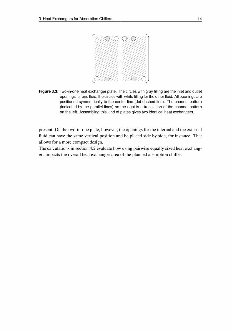
3.3.3 Integrating Two Heat Exchangers on One Plate
Pairwise equal heat exchangers can be made on one and the same plate. Consider figure3.3, depicting the sketch of a plate with the pattern for two equal heat exchangers. Sucha two-in-one heat exchanger plate must be symmetric as to the fluid inlet and outletopenings, whereas the channel pattern of the right heat exchanger is a translation of theleft one. Thus, when two plates are assembled to a plate package - one of them has tobe turned over around the center line first -, the corresponding fluid openings coincideand hence allow for the necessary fluid flow to and from the adjacent plate packages.
The channels form the cavity system in the same manner as they do for conventional,single, heat exchangers. That means that the cavities for the external fluid form a closedsystem - with exception for the inlet and outlet openings - and that the vapor side isopen. Consequently, vapor can flow from one to the other heat exchanger - the vaporpiping can be omitted and the distances for the vapor to flow are short. Just as the in-tegration of the distribution system, omitting the vapor piping results in a simpler andcheaper assembly and lower material cost. And the short distances for the vapor flowresult in low pressure loss, which is favorable, too - see section 5.1.Another advantage of two-in-one plates is that the fluid inlet and outlet openings do nothave to be located in the center, even though a plate package consists of two identicalplates. Thanks to the symmetrical arrangement on the left and the right heat exchanger,the respective openings coincide in spite. The openings for external and internal fluid donot have to be placed on top of each other, which would result in increased unused areason the top and the bottom of the heat exchanger, where only one of the fluids would be
3 Heat Exchangers for Absorption Chillers 14
Figure 3.3: Two-in-one heat exchanger plate. The circles with gray filling are the inlet and outletopenings for one fluid, the circles with white filling for the other fluid. All openings arepositioned symmetrically to the center line (dot-dashed line). The channel pattern(indicated by the parallel lines) on the right is a translation of the channel patternon the left. Assembling this kind of plates gives two identical heat exchangers.
present. On the two-in-one plate, however, the openings for the internal and the externalfluid can have the same vertical position and be placed side by side, for instance. Thatallows for a more compact design.The calculations in section 4.2 evaluate how using pairwise equally sized heat exchang-ers impacts the overall heat exchanger area of the planned absorption chiller.

4 Modeling of Absorption Chiller Cycle Concepts
The present work is a step in the engineering of a new absorption chiller that usesplate heat exchangers as main components. The chillers’ planned capacity is four kilo-watts; table 4.1 lists the planned external temperatures. The intention is to design anabsorption chiller that can use water heated with reject heat from a combined heat andpower plant or water heated by solar collectors. These heat sources can heat water torather moderate temperatures. Therefore, the respective hot water is called low tem-perature hot water. A typical temperature level of low temperature hot water is ninetydegrees Celsius. Thus, the planned inlet temperature for the hot water is ninety degreesCelsius. The planned cooling water inlet temperature is thirty degrees Celsius becausethat comparably high cooling water temperature requires a smaller cooling tower thana lower cooling temperature, as, for instance, 27 degrees Celsius. And moreover, thirtydegrees Celsius may even be reached with a dry cooling tower, which is easier to installand less expensive than a wet cooling tower. Lastly the chilled water inlet and outlettemperature is fifteen and ten degrees, respectively - suitable for air conditioning.
Table 4.1: Planned external temperatures for the absorption chiller
temperatures [◦C] inlet outlet
chilled water 15 10
cooling water 30 38
hot water 90 80
This section presents a number of results from numerical cycle calculations. Thegoal of these calculations is to evaluate different cycle designs and to give an idea ofthe required heat exchanger areas and the achievable coefficient of performance (COP).Moreover, the calculations show whether the planned external temperatures are ade-quate for the planned cycles - here, especially the use of a pool generator is critical, assection 4.3 will show.In the mathematical model, an equation system consisting of energy, mass and saltbalances in the main components evaporator, absorber, generator and condenser, andin the solution heat exchanger, describes the absorption chiller cycle. The commer-cial software Engineering Equation Solver (EES) solves the equation system. More-over, EES provides a library with the relevant physical properties of water and aqueouslithium bromide solution, the two substances present in the absorption chiller, the so-called working pair. The library is based on data in [Parsons & Forman (1989)] and

4 Modeling of Absorption Chiller Cycle Concepts 16
[Uemura & Hasaba (1964)].The cycle models are based on the following assumptions and simplifications4:
• The system is in a steady state. That is, the mass flow rate of water vapor ab-sorbed in the absorber is equivalent to the mass flow rate of water vaporized inthe generator.
• The pressure drop inside the piping and the vessels is negligible.
• The heat transported between any of the components of the cooling machine andthe surroundings is negligible.
• The main component (evaporator, absorber, generator and condenser) heat ex-changers and the solution heat exchanger have constant overall heat transfer co-efficients U.
• The heat exchangers are fully wetted.
Note that the used U-values have been measured in a ten kilowatt absorption chillerwith tube bundle heat exchangers and with similar external temperatures. As no othernumbers are available, we assume that the main component heat exchangers and the so-lution heat exchanger of the modeled cycles have all about the same overall heat transfercoefficients as the respective heat exchangers of the ten kilowatt chiller: Uevaporator =1.2 kW/m2K, Ucondenser = 2.0 kW/m2K, Uabsorber = 1.0 kW/m2K and Ugenerator = 0.8kW/m2K. Tests with prototype heat exchangers will have to show in how far the esti-mated U-values differ from the real ones.
As stated in the introduction, the specific heat exchanger area is one of the factorsdefining the costs of an absorption chiller. It is defined as the overall heat exchangerarea of the absorption chiller divided by the cooling capacity of the chiller. Moreover,the specific heat exchanger area influences the size of the main components and thusalso the size of the entire absorption chiller. As both low costs and a small size of thechiller are favorable, the cycle modeling aims at a minimum heat exchanger area ateach calculated operating point. The chiller capacity is four kilowatts for all calcula-tions, hence the calculated absolute heat exchanger areas can easily be transformed intospecific areas if the reader is interested in specific areas.
This chapter has the following structure: The first section evaluates two conceptsof solution recirculation at the absorber, the second section investigates the impactof using pairwise equally sized heat exchangers for absorber/evaporator and genera-tor/condenser, and the third section examines if the planned external temperatures allowfor the use of a pool generator.
4The first three of these assumptions correspond to the assumptions of [Joudi & Lafta (2000)].

4 Modeling of Absorption Chiller Cycle Concepts 17
4.1 Modeling of Absorber Recirculation
First, this section answers the question why to consider solution recirculation at theabsorber. Then the modeled recirculation concepts are presented, followed by the resultsof the cycle calculations and their discussion.
4.1.1 Motivation for Absorber Recirculation
Plate heat exchangers do not wet as well as tube bundle heat exchangers. The presumedreason for that drawback is the vertical and continuous geometry. Compared to tubebundles, which have convex surfaces and where solution collects at the bottoms of thetubes before dripping off to the next tube, the solution flows faster on a plate. Therefore,larger solution mass flow rates are necessary to keep up a contiuous film, which resultsin an efficient use of the plate heat exchanger. The calculation in appendix A estimatesthe solution mass flow necessary to attain good wetting of the plate heat exchanger pre-viously investigated at the ZAE Bayern. That mass flow rate refers to one plate package,that is, the surfaces of two adjacent plates. The absorber heat exchanger, and the otherheat exchangers as well, however, will consist of several, say n, plate pairs.5 Conse-quently, the mass flow rate needed for good wetting will be n times as much as the massflow rate for one package. And so will the area.Yet, the modeling does not return integer multiples of the plate pair surface area. EESsolves the equation system describing an absorption chiller cycle with the task to min-imize the overall heat exchanger area. But it does not know what plate size will beused for the heat exchangers,6 so the returned heat exchanger areas will usually be non-integer multiples of the intended plate surface area and can be seen as a lower limit forthe heat exchanger design.Again, the cycle model is based on the assumption of good wetting. And plate heatexchanger wetting is good when the solution mass flow rate is sufficient. Hence we de-fine a ratio of the solution mass flow rate applied on the absorber and the absorber area;let us name that ratio specific mass flow rate. The calculations in appendix A, basedon wetting tests by [Beil (2011)], show that the minimum specific mass flow rate forthe current heat exchanger design is some 0.15 kg/m2s. The calculated absorber heatexchanger area is only realistic for a specific mass flow rate of at least that value.7
In a basic single-effect absorption chiller cycle, the solution mass flow rate applied
5n is an integer.6In fact, the used equation systems are not limited to the calculation of absorption chillers with plateheat exchangers. They can be used for absorption chillers with any other kind of heat exchanger, aslong as the assumptions and constraints of the equation system suit the heat exchanger type in question.
7Note that the specific mass flow rate necessary for good wetting depends, inter alia, on the plate width.When changing the plate width notably, an adjustment of the specific mass flow rate will be necessaryto keep wetting on a good level. Therefore, the specific mass flow rate could also refer to the mass flowrate per plate width. Both ratios can, however, be transformed into one another.

4 Modeling of Absorption Chiller Cycle Concepts 18
on the absorber equals the mass flow rate of poor solution coming from the generator. Ifthis mass flow rate is to be increased in order to provide the specific solution mass flowrate necessary for good wetting, more solution circulates between absorber and gener-ator, which is expressed by a rising solution circulation ratio f. The increased solutionmass flow rates in turn increases the required pump work and the losses in the solutionheat exchanger, both decreasing the overall efficiency of the chiller. Figure 4.1 showsthe specific mass flow rate at the absorber as a function of f for the cycle model withthe external temperatures given in table 4.1. The graph shows that f must be far beyondthe plotted range so the specific mass flow rate reaches the threshold for good wetting.As the discussion in section 4.1.3 shows, for an f far beyond twenty-five, the total heatexchanger area is high, which is the opposite of what we aim at, and the COP becomesreally poor, which is unfavorable as well. So, increasing f in order to attain good wettingis not the right approach.
0.00
0.05
0.10
0.15
0.20
6 8 10 12 14 16 18 20 22 24 26
mp
oo
r/A
ab
s[k
g/m
²s]
f
good wetting
poor wetting
Figure 4.1: Specific solution mass flow rate at the absorber of the basic cycle. The dashed linemarks the threshold for good wetting.
However, the specific mass flow rate at the absorber can be independent of the massflow rate circulating between the absorber and the generator. Solution recirculation atthe absorber provides this independence. It allows for an increase of the solution massflow rate applied on the absorber heat exchanger at constant mass flow rates betweenabsorber and generator. Thus, we can prescribe a constant specific mass flow rate andoptimize other variables in the cycle model.
4.1.2 Modeled Recirculation Concepts
The cycle calculations encompass two concepts for solution recirculation at the ab-sorber:
• Mixed recirculation: Rich solution is taken from the absorber sump and mixedwith the poor solution coming from the generator. The mixed solution is then
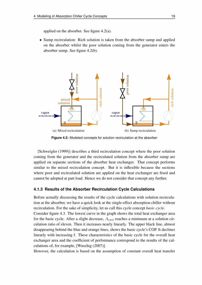
4 Modeling of Absorption Chiller Cycle Concepts 19
applied on the absorber. See figure 4.2(a).
• Sump recirculation: Rich solution is taken from the absorber sump and appliedon the absorber whilst the poor solution coming from the generator enters theabsorber sump. See figure 4.2(b).
vapor
rich
solu
tion
poor
solu
tion
mixedsolution
(a) Mixed recirculation
vapor
rich
solu
tion
poor
solu
tion
(b) Sump recirculation
Figure 4.2: Modeled concepts for solution recirculation at the absorber
[Schweigler (1999)] describes a third recirculation concept where the poor solutioncoming from the generator and the recirculated solution from the absorber sump areapplied on separate sections of the absorber heat exchanger. That concept performssimilar to the mixed recirculation concept. But it is inflexible because the sectionswhere poor and recirculated solution are applied on the heat exchanger are fixed andcannot be adopted at part load. Hence we do not consider that concept any further.
4.1.3 Results of the Absorber Recirculation Cycle Calculations
Before actually discussing the results of the cycle calculations with solution recircula-tion at the absorber, we have a quick look at the single-effect absorption chiller withoutrecirculation. For the sake of simplicity, let us call this cycle concept basic cycle.Consider figure 4.3. The lowest curve in the graph shows the total heat exchanger areafor the basic cycle. After a slight decrease, Atotal reaches a minimum at a solution cir-culation ratio of eleven. Then it increases nearly linearly. The upper black line, almostdisappearing behind the blue and orange lines, shows the basic cycle’s COP. It declineslinearly with increasing f. These characteristics of the basic cycle for the overall heatexchanger area and the coefficient of performance correspond to the results of the cal-culations of, for example, [Wuschig (2007)].However, the calculation is based on the assumption of constant overall heat transfer

4 Modeling of Absorption Chiller Cycle Concepts 20
0.55
0.60
0.65
0.70
0.75
0.80
2.5
3.0
3.5
4.0
4.5
5.0
6 8 10 12 14 16 18 20 22 24 26
CO
P
Ato
tal[m
²]
f
basic cycle
mixed recirculation
sump recirculation
Atotal
COP
Figure 4.3: Overall area optimized calculation of cycle concepts
coefficients - which are valid for good wetting. As stated in section 4.1.1, good wettingof the plate heat exchanger requires a certain solution mass flow rate per area; some0.15 kg/m2s for the current plate design. Now, figure 4.1 shows that the solution massflow rate applied per absorber heat exchanger area for the basic cycle is far below therequired value of 0.15 kg/m2s. Thus, wetting of the absorber heat exchanger will bepoor. Hence the heat exchanger area will not be large enough to provide the heat andmass transfer rates necessary for the design chilling performance.Consequently, the result for the basic cycle shown in figure 4.3 may be well valid forbundled tube heat exchangers, but not for a plate heat exchanger type as we intend touse. Now, how can the heat exchanger wetting be enhanced? As elaborated in section4.1.1, by solution recirculation rather than by increasing f.For the cycle calculation of the recirculation concepts, we prescribe a specific solutionmass flow rate of 0.15 kg/m2s, thus providing good wetting. Hence, the calculatedabsorber heat exchanger area is sufficient because it provides enough heat and masstransfer area for the vapor absorption, in contrast to the basic cycle concept without so-lution recirculation, which does not provide good wetting.
The orange and blue curves in figure 4.3 show the total heat exchanger area and COPfor mixed recirculation and sump recirculation at the absorber. Especially for low val-ues of f, both recirculation concepts’ Atotal is significantly larger than the basic cycle’s

4 Modeling of Absorption Chiller Cycle Concepts 21
Atotal. This is due to the different concentrations of the solution applied on the absorberheat exchanger:In the basic cycle, poor solution coming from the generator is applied on the absorberheat exchanger. Having a low water concentration, this solution can absorb much va-por. In the cycles with recirculation however, rich solution from the absorber sump isapplied on the absorber heat exchanger, either pure or mixed with poor solution comingfrom the generator. In either case, the applied solution contains much more water thanthe poor solution. Hence, more solution is necessary to absorb the vapor coming fromthe evaporator. With the specific mass flow rate (that is, mass flow rate of the appliedsolution divided by the absorber heat exchanger area) being constant, an increased solu-tion mass flow rate also means an increased absorber heat exchanger area. For f below23, the cycle with sump recirculation has a somewhat larger total heat exchanger areathan the cycle with mixed recirculation. That difference is mainly because of the largerabsorber area, see figure 4.4, where the two upper curves depict the absorber heat ex-changer area for the two recirculation concepts. The larger absorber area in turn resultsfrom the higher water content of the applied solution: The richer solution can absorbless water.
20
40
60
80
100
120
140
160
180
200
0.0
0.2
0.4
0.6
0.8
1.0
1.2
1.4
1.6
6 8 10 12 14 16 18 20 22 24 26
f R
Aa
bs
[m²]
f
mixed recirculation
sump recirculationAabs
fR
Figure 4.4: Absorber heat exchanger area and recirculation ratio for absorption cycles withsolution recirculation at the absorber
Figure 4.4 also depicts the solution recirculation ratio fR, defined as the ratio of themass flow rate of the recirculated solution and the refrigerant mass flow rate:
fR =mrecirc
mrefr
. (4)

4 Modeling of Absorption Chiller Cycle Concepts 22
For the sump recirculation concept, only the recirculated solution is applied on the ab-sorber, whereas the poor solution coming from the generator flows into the absorbersump. Hence, the specific mass flow rate, that is, the mass flow rate applied on theabsorber per absorber area, is
mspec,sump =mrecirc
Aabs
, (5)
and the recirculation ratio writes
fR,sump =mrecirc
mrefr
=mspec · Aabs
mrefr
. (6)
For the mixed recirculation concept however, the poor solution coming from the gen-erator is part of the solution that is applied on the absorber and the specific mass flowrate writes
mspec =mrecirc +mpoor
Aabs
. (7)
With mpoor being
mpoor = mrich −mrefr = mrefr(f − 1), (8)
this term becomes
mspec =mrecirc +mrefr(f − 1)
Aabs
(9)
and solving for mrecirc yields
mrecirc = mspec · Aabs −mrefr(f − 1), (10)
and finally the recirculation ratio for mixed recirculation writes
fR,mixed =mrecirc
mrefr
=mspec · Aabs
mrefr
− f + 1. (11)
Equations (6) and (11) show that for mixed recirculation, the solution circulation ratiof influences the recirculation ratio fR considerably more than it does for sump recircula-tion. fR,sump is only influenced by f via the absorber area, which is a function of f. Theequation for fR,mixed, however, additionally contains the term -f. That explains the formof the fR,mixed curve in figure 4.4: With the curve for the absorber area approaching alinear shape with increasing f, the term mspec·Aabs
mrefrvirtually becomes constant. Hence,
the curve for fR,mixed approaches a linear function with the slope -f. As the slope offR,sump is larger than f, the two curves diverge. Within the relevant range of f, the dif-ference is moderate, and thus also the additional pump work. Consequently, the higherrecirculation mass flow rate of the sump recirculation concept is not a decisive criterionagainst the concept.
4 Modeling of Absorption Chiller Cycle Concepts 23
One more look at figure 4.3 shows that for mixed recirculation, the COP is virtu-ally equal to the COP of the basic cycle whereas the sump recirculation cycle’s COP issomewhat better for f larger than twelve. However, the differences are relatively smallfor moderate values of f. And as to area optimization, an increase of f beyond, say,sixteen, has only little effect. For mixed recirculation, Atotal even begins to rise again atan increase of f beyond eighteen.What conclusions can we draw from these results? First, solution recirculation is apromising approach to improve wetting of the absorber plate heat exchanger. Second,mixed recirculation and sump recirculation perform similarly. From the heat exchangerarea and COP point of view, they are more or less equal. Sump recirculation requiressomewhat more pump work for the solution recirculation. Third, there is no absolutedesign optimum. The design is a compromise between reaching a low heat exchangerarea and a good COP. While the heat exchanger area determines the material costs, theweight, and the achievable compactness of an absorption chiller, the COP determinesthe energy input needed for a certain chilling performance and thus impacts the runningcosts. A more detailed evaluation of economic and energetic aspects as, for instance,material prices and the necessity to reduce the operating energy consumption is nec-essary to decide on the best compromise between low heat exchanger area and highCOP.
4.2 Equal Heat Exchanger Sizes
In the previous section, we discussed solution recirculation at the absorber as an ap-proach to overcome the poor wetting of the used plate heat exchangers and the badperformance connected with it. Now we will investigate another design approach, onethat has little to do with performance enhancement but more with cost reduction: Equalheat exchangers. The question we are going to discuss is: What impact does it have onthe overall heat exchanger area and the COP, if (1) the absorber and the evaporator and(2) the absorber and the evaporator, and the generator and the condenser, have pairwisethe same size, that is, the same heat exchanger area.The motivation for this question is: If pairwise equal heat exchangers can be used inthe absorption chiller, fewer heat exchangers have to be engineered and fewer heat ex-changer variants have to be produced. Moreover, the pairwise equal heat exchangers,could even be made on the same plate. For instance, the absorber and the evaporatoron one plate. Production and assembly costs of the main components would reducenotably, as illustrated in section 3.3. Thus, equal heat exchangers are a promising ap-proach to reduce the production costs for the absorption chiller and thus the first cost ofthe chiller. If the absorption chiller shall have a chance to establish on the market, itsfinal price must not be significantly higher than the final price of compression chillerswith comparable capacity.
Now, what impact does it have on the entire absorption chiller if the absorber and the

4 Modeling of Absorption Chiller Cycle Concepts 24
evaporator heat exchanger are equal? And if additionally the condenser is equal to thegenerator? Consider figure 4.5, depicting the result of cycle calculations with the sameinput data as for the previous cycle calculations, but with the modification that (1) theabsorber and the evaporator are equal in size (Aabs = Aevap, medium colored curves),and (2) additionally the condenser and the generator are equal in size (Aabs = Aevap
and Agen = Acon, light colored curves). The dark colored curves are for individuallyoptimized heat exchanger areas, that is, equal to the curves in figure 4.3.
2.5
3.0
3.5
4.0
4.5
6 8 10 12 14 16 18 20 22 24 26
Ato
tal[m
²]
f
basic cycle
mixed recirculation
sump recirculation
Figure 4.5: Overall heat exchanger area with different cycle designs and area optimizationconcepts. Dark colored curves: Minimum overall heat exchanger area; individualoptimization for every heat exchanger. Medium colored curves: Aabs = Aevap. Lightcolored curves: Aabs = Aevap and Agen = Acon.
The dark and medium colored lines are close together. For mixed recirculation (or-ange curves), it is even hard to distinguish between them as the medium orange curve isonly slightly above the dark orange curve. In other words: Making the heat exchangerareas of absorber and evaporator equal results in a negligible increase of the overall heatexchanger area.However, the light colored curves are considerably above the dark and medium coloredcurves. That means, making not only the absorber and evaporator, but also the generatorand condenser pairwise equal does increase the overall heat exchanger area comparedto an individual optimization of all main component heat exchanger areas. For mixedrecirculation, this impact is somewhat stronger than for sump recirculation; the distance

4 Modeling of Absorption Chiller Cycle Concepts 25
between the light, and the medium and dark colored curve is larger than it is for sumprecirculation.
On the one hand, the previous results show that compared to sump recirculation,mixed recirculation results in a somewhat lower overall heat exchanger area and aslightly lower or equal COP. On the other hand, sump recirculation has constructive ad-vantages compared to mixed recirculation. The pump for the rich solution must increasethe pressure far enough so that the rich solution can enter the absorber. Depending onhow the mixed solution is applied on the absorber heat exchanger, the pressure afterthe pump may have to be even higher than the internal pressure in the generator. Inthat case, however, the poor solution coming from the generator will be stopped fromflowing to the absorber. Hence, simply connecting the pipes as sketched in figure 4.2(a)does not work. As sump recirculation is easier to carry out and has only slight disad-vantages as to COP and heat exchanger area, it is the preferable recirculation concept.So, let us have one more close look on the results of the cycle calculation for the sumprecirculation concept, depicted in figure 4.6.
0.55
0.6
0.65
0.7
0.75
0.8
3.0
3.5
4.0
4.5
5.0
6 8 10 12 14 16 18 20 22 24 26
CO
P
Ato
tal[m
²]
f
sump recirculation
1
2
3
minimum Atotal
Aabs = Aevap
Aabs = Aevap & Acon = Agen
COP
Atotal
Figure 4.6: Overall heat exchanger area and COP for the sump recirculation concept
Besides the overall heat exchanger area, the diagram also shows the COPs for the dif-ferent heat exchanger optimization concepts. Making the evaporator and the absorberequal has little effect, both on the area and the COP. Yet, as found above, if also the con-denser is equal to the generator, the overall heat exchanger area is considerably larger,which is a disadvantage. As figure 4.6 shows, however, also the COP increases a bit,
4 Modeling of Absorption Chiller Cycle Concepts 26
which is favorable. The reason for this COP increase is that with larger heat exchangers,lower temperature differences between the fluids are needed to transfer the same amountof heat, and thus the losses are lower and the heat transfer is more efficient. Hence, thedriving heat needed for the four kilowatt chilling capacity decreases.
4.3 Pool Generator
After having investigated the effect of recirculation and making the heat exchangerspairwise equal, we will now elaborate whether using a pool generator is promising forour design problem. This sections consists of four subsections. The first subsectionpresents the concept of and the motivation for using a pool generator, as well as pos-sible constraints. The second subsection briefly states the assumptions for the modelof the pool generator. The third subsection contains a calculation estimating the heattransfer coefficient for the flooded plate heat exchanger. Lastly, the fourth subsectionpresents the results of the calculations for the absorption chiller cycle with sump recir-culation and pool generator.
4.3.1 Concept, Motivation and Constraints of a Pool Generator
Pool generator means that the solution is not applied on top of the heat exchanger andthen forms a falling film flowing down along the heat exchanger plates, as it works infalling film heat exchangers. Instead, the generator is a pool, partly filled with solutionand the generator heat exchanger is partly flooded by the solution [Estiot (2009)].In the pool, nucleate boiling generates vapor bubbles. Because of the low pressure inthe generator - in our case some seventy millibars -, the specific volume of the vapor isvery high and thus the solution bubbles intensely. The intense bubbling makes solutionsplash on the upper part of the heat exchanger - the part that is above the solution sur-face and that is dry when the solution is in rest. In this way, the entire heat exchanger iswetted with solution.Now, why use a pool generator, what are its advantages? First, thanks to the intensebubbling, pool boiling provides good wetting without recirculation. Recirculation at theabsorber works without an additional pump, because one and the same pump can de-liver the recirculated solution and the solution leaving to the generator. At the generatorhowever, the outgoing solution does not have to be pumped because the pressure dropfrom the generator to the absorber is sufficient to make the solution flow from the gener-ator to the absorber. Hence solution recirculation at the generator requires an additionalpump. A pool generator however does not need recirculation and hence not need thatadditional pump. That saves both pump work and the weight and money for the pump.Moreover, the piping for the recirculated solution can be omitted.Second, as the pool generator is simply flooded with solution, it does not need any solu-
4 Modeling of Absorption Chiller Cycle Concepts 27
tion application system. To sum up the first two advantages, pool boiling reduces bothweight and costs of the generator - even if the additional solution in the generator sumpincreases the weight somewhat.Third, pool boiling promises higher heat transfer rates and thus a smaller heat exchangerarea than film boiling. [Estiot (2009)] showed the benefit of operating a generator with atube bundle heat exchanger in pool boiling mode if the wall superheat is at least thirteenKelvin. Assumed that pool boiling is as effective in plate heat exchangers, pool boilingallows for reduction of the generator heat exchanger and consequently reduces weightand costs, too.
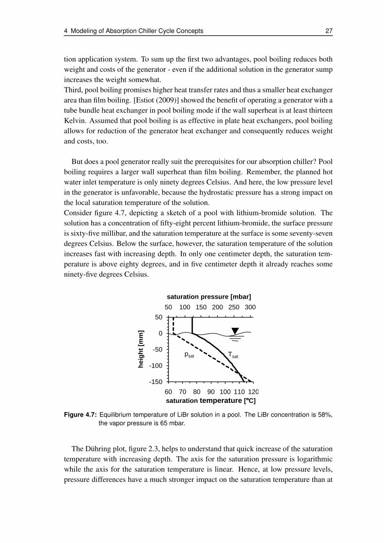
But does a pool generator really suit the prerequisites for our absorption chiller? Poolboiling requires a larger wall superheat than film boiling. Remember, the planned hotwater inlet temperature is only ninety degrees Celsius. And here, the low pressure levelin the generator is unfavorable, because the hydrostatic pressure has a strong impact onthe local saturation temperature of the solution.Consider figure 4.7, depicting a sketch of a pool with lithium-bromide solution. Thesolution has a concentration of fifty-eight percent lithium-bromide, the surface pressureis sixty-five millibar, and the saturation temperature at the surface is some seventy-sevendegrees Celsius. Below the surface, however, the saturation temperature of the solutionincreases fast with increasing depth. In only one centimeter depth, the saturation tem-perature is above eighty degrees, and in five centimeter depth it already reaches someninety-five degrees Celsius.
50 100 150 200 250 300
-150
-100
-50
0
50
60 70 80 90 100 110 120
saturation pressure [mbar]
he
igh
t [m
m]
saturation temperature [ C]
psat Tsat
Figure 4.7: Equilibrium temperature of LiBr solution in a pool. The LiBr concentration is 58%,the vapor pressure is 65 mbar.
The Dühring plot, figure 2.3, helps to understand that quick increase of the saturationtemperature with increasing depth. The axis for the saturation pressure is logarithmicwhile the axis for the saturation temperature is linear. Hence, at low pressure levels,pressure differences have a much stronger impact on the saturation temperature than at

4 Modeling of Absorption Chiller Cycle Concepts 28
high pressure levels. At a fifty-eight percent concentration, the lithium-bromide solutionhas a density of some 1600 kg/m3. That means, for every ten millimeters of depth, thehydrostatic pressure in the pool rises by almost 1.6 millibar, which is much comparedto the sixty-five millibar surface pressure. Now, another look at the Dühring plot showswhy the saturation temperature in the pool rises so quickly.
4.3.2 How to Model a Pool Generator
As elaborated above, the hydrostatic pressure has a notable influence on the local sat-uration - that is, boiling - temperature. Hence the model for the numerical calculationshould take this interrelation into account. To calculate local heat transfer coefficientsin a tube bundle pool generator, [Estiot (2009)] used the local saturation temperaturesof the solution in the middle of the respective tube.This discretization can be carried over and be used to model a pool generator with a plateheat exchanger. Figure 4.8 sketches how to carry out the discretization. For the heat ex-changer, we assume a height of one hundred millimeters. Half of the heat exchangeris flooded, so the height of the solution to be discretized is fifty millimeters. Theseheights for the heat exchanger and the solution correspond to those in [Estiot (2009)],for which Estiot found in her experiments that the pool generator performed well. Themodel discretizes the solution, which is fifty millimeters high, into one hundred layers,so each layer’s height dh is a half millimeter. For every layer, the local pressure and therespective saturation temperature are determined, under the assumption that concentra-tion gradients within the pool are negligible.
x
h
heat exchanger plate
solutionAii
i+1
i-1
dh
p(hi) Tsat(hi)
HW inlet(hot side)
HW outlet(cold side)
hi
Figure 4.8: Discretization of the flooded part in the pool generator
The saturation temperature of the solution in the pool increases with increasing depth,yet we assume that because of good mixing there is no horizontal temperature gradienton the solution side. But as the flow direction of the hot water (HW) on the other sideof the heat exchanger plate is horizontal and water loses heat as it heats the solution,there is a horizontal temperature gradient on the water side. We assume however thatthe vertical temperature gradient on the water side is negligible because the forced flow

4 Modeling of Absorption Chiller Cycle Concepts 29
results in good vertical mixing.Because of the vertical temperature gradient in the pool, the heat transfer rate is a func-tion of the depth. The local logarithmic mean temperature difference is
lmtd(h) =(tHW,in − tpool(h)) − (tHW,out − tpool(h))
ln(
tHW,in−tpool(h)tHW,out−tpool(h)
) (12)
and rewriting yields
lmtd(h) =tHW,in − tHW,out
ln(
tHW,in−tpool(h)tHW,out−tpool(h)
) . (13)
Now, the heat transfer rate in the layer i is
qi = Ai · Ui · lmtd(hi), (14)
where Ai is the area of one layer and equal for all layers, and Ui is the overall heattransfer coefficient for h = hi. Let us assume that, within the small height of the pool,the overall heat transfer coefficient is constant, Upool. Then the heat transfer rate for theflooded part of the generator is the sum of the heat transfer rates of all layers:
qflooded =∑i
qi = Ai · Upool ·∑i
lmtd(hi). (15)
The flow regime of pool boiling in a plate heat exchanger differs much from that in a hor-izontal tube bundle. Hence, the overall heat transfer coefficient Upool is not a value mea-sured by [Estiot (2009)] but an estimation based on the findings of [Lee et al. (1991)]and [Kaji et al. (1995)], see section 4.3.3 below.
According to the model, the intense boiling splashes saturated solution from the poolon the upper part of the generator heat exchanger. The solution then forms a falling film,hence the upper half of the generator is calculated as a falling film heat exchanger.
4.3.3 Convective Heat Transfer Coefficient in the Pool
Other than for the falling film heat exchangers, where we could use measured U-valuesof a tested absorption chiller, little information is available on the heat transfer coeffi-cients of pool generators. [Estiot (2009)] investigated subatmospheric pool boiling ofaqueous LiBr-solution for plain and finned horizontal tube bundle heat exchangers, butnot for vertically arranged plate heat exchangers as we will model. Also most otherpublications on subatmospheric pool boiling of aqueous LiBr-solution refer to horizon-tal tubes, mostly single tubes, or horizontal plates.In contrast to falling film boiling, buoyancy plays an important role in pool boiling.Buoyancy forces vapor bubbles to move upwards, and that motion substantially rules

4 Modeling of Absorption Chiller Cycle Concepts 30
the flow regime in the pool and thus the convective heat transfer. The bubble motionhowever is influenced by the arrangement of the heat exchanger - be it consisting oftubes or of plates -, because the arrangement determines the paths the bubbles can take.For instance, the flows between the tubes of a horizontal tube bundle and a vertical tubebundle differ. Different flows, however, result in different convective heat transfer co-efficients. For example, single vertical tubes reach a higher heat transfer than singlehorizontal tubes in subatmospheric LiBr-solution [Lee et al. (1991)].Concludingly, it is advisable to estimate the convective heat transfer coefficient of thepool generator we will model by means of data referring to vertically arranged heat ex-changers, because our plate heat exchanger will also be arranged vertically.
[Lee et al. (1991)] and [Kaji et al. (1995)] made experiments with a vertical tube anda vertical plate, respectively, and determined the convective heat transfer coefficientfor subatmospheric pool boiling of aqueous lithium-bromide solution. Lee et alii im-mersed an eleven millimeter diameter and 120 millimeter long cylinder in aqueous LiBr-solution with a 55 percent LiBr mass fraction. They heated the cylinder and determinedthe heat transfer coefficient in the middle of the cylinder, that is, 60 millimeters belowthe surface of the solution. They conducted measurements at varying wall superheatand at four different system pressures between 30 and 300 torr, that is, between 40 and400 millibars. The diagram in figure 4.9 plots the measured convective heat transfer co-efficients at 40, 93 and 200 millibars, for a twelve Kelvin wall superheat - which shouldbe enough for a well-working pool generator [Estiot (2009)].
0
500
1000
1500
2000
2500
0 50 100 150 200 250
h [
W/m
²K]
p [mbar]
Figure 4.9: Convective heat transfer coefficients of boiling aqueous LiBr solution measured by[Lee et al. (1991)]. ∆TW = 12K, xLiBr = 55%. Dashed line: linear fit.
A linear fit - the dashed line in the graph - points on a linear correlation betweenthe saturation pressure and the heat transfer coefficient in the range between 40 and200 millibars. Based on the previous cycle calculation results, we assume a 70 millibarpressure in the generator, a pressure located within the linear range between 40 and200 millibars. Hence, linear interpolation yields the estimated convective heat transfer
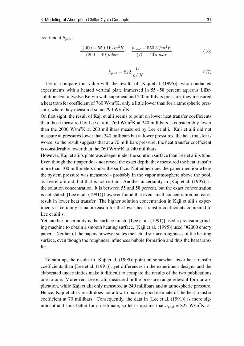
4 Modeling of Absorption Chiller Cycle Concepts 31
coefficient hpool:
(2000 − 550)W/m2K
(200 − 40)mbar=hpool − 550W/m2K
(70 − 40)mbar(16)
hpool = 822W
m2K(17)
Let us compare this value with the results of [Kaji et al. (1995)], who conductedexperiments with a heated vertical plate immersed in 55∼58 percent aqueous LiBr-solution. For a twelve Kelvin wall superheat and 240 millibars pressure, they measureda heat transfer coefficient of 760 W/m2K, only a little lower than for a atmospheric pres-sure, where they measured some 790 W/m2K.On first sight, the result of Kaji et alii seems to point on lower heat transfer coefficientsthan those measured by Lee et alii. 760 W/m2K at 240 millibars is considerably lowerthan the 2000 W/m2K at 200 millibars measured by Lee et alii. Kaji et alii did notmeasure at pressures lower than 240 millibars but at lower pressures, the heat transfer isworse, so the result suggests that at a 70 millibars pressure, the heat transfer coefficientis considerably lower than the 760 W/m2K at 240 millibars.However, Kaji et alii’s plate was deeper under the solution surface than Lee et alii’s tube.Even though their paper does not reveal the exact depth, they measured the heat transfermore than 100 millimeters under the surface. Not either does the paper mention wherethe system pressure was measured - probably in the vapor atmosphere above the pool,as Lee et alii did, but that is not certain. Another uncertainty in [Kaji et al. (1995)] isthe solution concentration. It is between 55 and 58 percent, but the exact concentrationis not stated. [Lee et al. (1991)] however found that even small concentration increasesresult in lower heat transfer. The higher solution concentration in Kaji et alii’s exper-iments is certainly a major reason for the lower heat transfer coefficients compared toLee et alii’s.Yet another uncertainty is the surface finish. [Lee et al. (1991)] used a precision grind-ing machine to obtain a smooth heating surface, [Kaji et al. (1995)] used "#2000 emerypaper". Neither of the papers however states the actual surface roughness of the heatingsurface, even though the roughness influences bubble formation and thus the heat trans-fer.
To sum up, the results in [Kaji et al. (1995)] point on somewhat lower heat transfercoefficients than [Lee et al. (1991)], yet differences in the experiment designs and theelaborated uncertainties make it difficult to compare the results of the two publicationsone to one. Moreover, Lee et alii measured in the pressure range relevant for our ap-plication, while Kaji et alii only measured at 240 millibars and at atmospheric pressure.Hence, Kaji et alii’s result does not allow to make a good estimate of the heat transfercoefficient at 70 millibars. Consequently, the data in [Lee et al. (1991)] is more sig-nificant and suits better for an estimate, so let us assume that hpool = 822 W/m2K, as
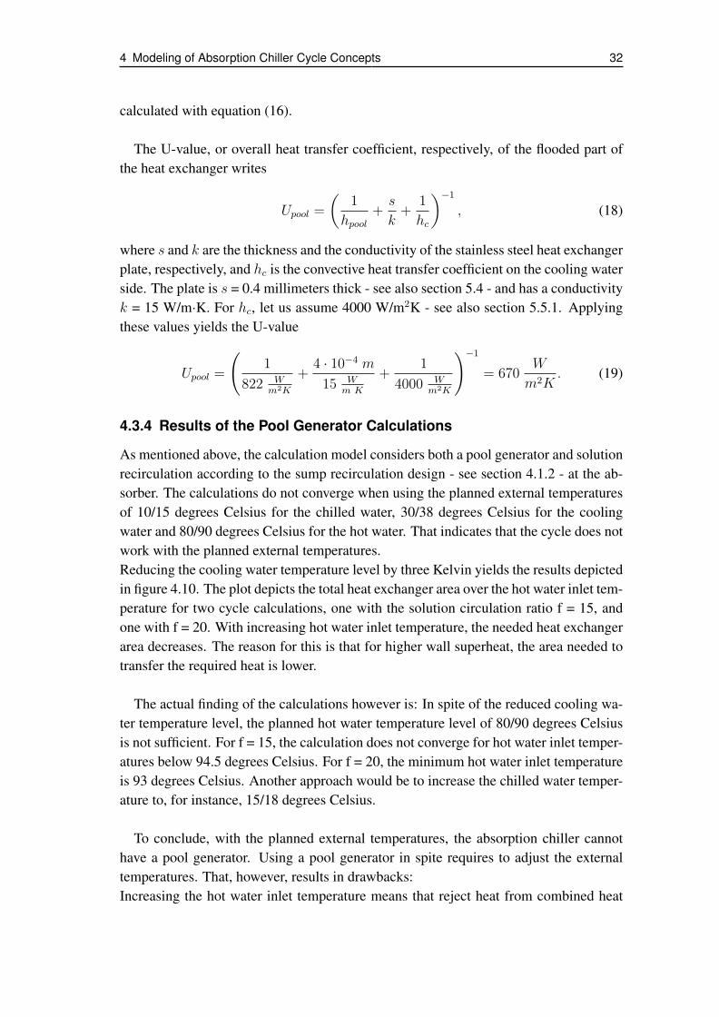
4 Modeling of Absorption Chiller Cycle Concepts 32
calculated with equation (16).
The U-value, or overall heat transfer coefficient, respectively, of the flooded part ofthe heat exchanger writes
Upool =
(1
hpool+s
k+
1
hc
)−1, (18)
where s and k are the thickness and the conductivity of the stainless steel heat exchangerplate, respectively, and hc is the convective heat transfer coefficient on the cooling waterside. The plate is s = 0.4 millimeters thick - see also section 5.4 - and has a conductivityk = 15 W/m·K. For hc, let us assume 4000 W/m2K - see also section 5.5.1. Applyingthese values yields the U-value
Upool =
(1
822 Wm2K
+4 · 10−4 m
15 Wm K
+1
4000 Wm2K
)−1= 670
W
m2K. (19)
4.3.4 Results of the Pool Generator Calculations
As mentioned above, the calculation model considers both a pool generator and solutionrecirculation according to the sump recirculation design - see section 4.1.2 - at the ab-sorber. The calculations do not converge when using the planned external temperaturesof 10/15 degrees Celsius for the chilled water, 30/38 degrees Celsius for the coolingwater and 80/90 degrees Celsius for the hot water. That indicates that the cycle does notwork with the planned external temperatures.Reducing the cooling water temperature level by three Kelvin yields the results depictedin figure 4.10. The plot depicts the total heat exchanger area over the hot water inlet tem-perature for two cycle calculations, one with the solution circulation ratio f = 15, andone with f = 20. With increasing hot water inlet temperature, the needed heat exchangerarea decreases. The reason for this is that for higher wall superheat, the area needed totransfer the required heat is lower.
The actual finding of the calculations however is: In spite of the reduced cooling wa-ter temperature level, the planned hot water temperature level of 80/90 degrees Celsiusis not sufficient. For f = 15, the calculation does not converge for hot water inlet temper-atures below 94.5 degrees Celsius. For f = 20, the minimum hot water inlet temperatureis 93 degrees Celsius. Another approach would be to increase the chilled water temper-ature to, for instance, 15/18 degrees Celsius.
To conclude, with the planned external temperatures, the absorption chiller cannothave a pool generator. Using a pool generator in spite requires to adjust the externaltemperatures. That, however, results in drawbacks:Increasing the hot water inlet temperature means that reject heat from combined heat

4 Modeling of Absorption Chiller Cycle Concepts 33
0
1
2
3
90 95 100 105 110
Ato
tal[m
²]
hot water inlet temperature [ C]
f = 20
f = 15
Figure 4.10: Atotal over the hot water inlet temperature for an absorption chiller with pool gen-erator and absorber sump recirculation. The hot water outlet temperature is tenKelvin below the respective inlet temperature. The cooling water temperaturesare 27/35 degrees Celsius and the chilled water temperatures are 10/15 degreesCelsius.
and power plants may be on a too low temperature level and hence no longer be suit-able. Moreover, it complicates the use of solar panels to produce the hot water. Eventhough solar panels can heat water to temperatures above 90 degrees Celsius, it is notfavorable: For flat plate collectors, losses increase and consequently a larger collectorarea is necessary, which increases the first cost. Evacuated tube collectors have lowertemperature-dependent losses and are therefore more suitable for higher temperatures.Nevertheless, they cost significantly more than flat plate collectors.A cooling water temperature level below 30/38 degrees Celsius requires a wet coolingtower. In contrast, depending on the local maximum outdoor temperatures, 30/38 de-grees cooling water can also be realized with a dry cooling tower, which is less costlythan a wet cooling tower [Natzer et al. (2010)]. If the local climate does not allow to usea dry cooling tower, however, higher cooling water temperatures still require a smallercooling tower, which reduces the application’s first cost. Hence, keeping the coolingwater temperature level at 30/38 degrees Celsius would be favorable.Increasing the chilled water temperature to, for instance, 15/18 degrees Celsius hasdrawbacks, too. That temperature level is too high to dry the chilled air. Thus, thechilled air becomes humid and that means a reduced comfort for the persons presentin the respective air conditioned room. Nevertheless, 15/18 degrees chilled water canprovide enough chill for radiant cooling, for instance with ceiling panels.
Note that the pool generator calculation is based on an overall heat transfer coefficientin the pool of Upool = 550 W/m2K, a somewhat more conservative estimation than theabove derived 670 W/m2K. When the present work was due to be finished, the remain-ing time was not sufficient to recalculate the cycle with the new U-value. Hence, thecalculation underestimates the heat transfer in the flooded part of the generator and thusoverestimates the required heat exchanger area. Qualitatively, however, that error does

4 Modeling of Absorption Chiller Cycle Concepts 34
not impair the validity of the following conclusion:
As becomes obvious, any adoption of the external temperatures has drawbacks. Butto realize the absorption chiller with a pool generator, at least one external temperaturelevel has to be adopted. Hence, a pool generator requires a compromise, weighing thedifferent options. Alternatively, the generator could still operate as a falling film heatexchanger.

5 CFD-based Heat Exchanger Design
This chapter aims at the improvement of a plate heat exchanger that was designed asa main component heat exchanger for absorption chillers but performs poorly. The firstsection gives a brief description of the current heat exchanger design and the reasons forits poor performance, and lists three design goals to improve the heat exchanger. Thesecond section states three design changes to attain the design goals identified in the firstsection. The third section briefly explains why CFD (Computational Fluid Dynamics)is used as design tool and the fourth section introduces the five heat exchanger designswhich are compared and evaluated in the last section of the chapter.
5.1 Design Goals for the New Heat Exchanger
[Behr (2006)] and [Hulin (2008)] investigated the plate heat exchanger depicted in fig-ure 5.1. The heat exchanger had been developed for the use in an absorption chiller.When tested as a falling film absorber, however, the heat exchanger performed worsethan expected.
Figure 5.1: The plate heat exchanger investigated by Hulin and Behr
Behr conducted wetting tests and found that wetting on the vapor side of the heatexchanger was poor. Good wetting however is crucial for a falling film absorber toperform well. Hence, Behr concluded that bad wetting is the major reason for the ab-sorber’s poor performance. Behr also calculated the heat transfer coefficient on thecooling water side and found that it cannot be the limiting factor of the absorber perfor-mance. Hulin confirmed Behr’s conclusion. He found that the flow on the water sideis well distributed and that the heat transfer on the water side is good: At a mass flow

5 CFD-based Heat Exchanger Design 36
rate as low as 0.006 kilogram water per second through one plate package8, Hulin founda value of 3000 W/m2K for the convective heat transfer coefficient on the water side.As good wetting is necessary for a good absorber performance and the current heat ex-changer wets poorly, the design of an improved absorber has to aim at improved wettingon the solution side.
Besides wetting, the vapor pressure loss is an important aspect of the absorber design.The absorber will operate at a pressure level of about ten millibars. At such a low pres-sure level, even a small pressure loss is adverse for the chiller performance. Considerthe Dühring-plot in figure 5.2. The saturation pressure on the right vertical axis is givenon a logarithmic scale while the horizontal axis for the solution saturation temperatureis given on a linear scale. Hence, even small pressure differences at low pressure levelshave a considerable impact on the solution saturation temperature.
6.1
10
20
50
100
0
10
20
30
40
50
0 10 20 30 40 50 60 70 80 90
satu
rati
on
pre
ssu
re [
mb
ar]
dew
-po
int
tem
pera
ture
of
wate
r [°
C]
saturation temperature of the solution [°C]
solubility limit
xLiBr 0% 40% 50%
60%
Figure 5.2: Dühring-plot with two different equilibrium states at x = 55%
Consider the following example for which the respective values are sketched in theDühring-plot, figure 5.2: In the absorber vessel of a lithium bromide absorption chiller,the pressure is ten millibars and the concentration of the lithium bromide solution isfifty-five percent. On its way from the edge to the center of the heat exchanger, thevapor loses two millibars. That is, the pressure at the center of the heat exchanger isonly eight millibars. So, at the edge of the heat exchanger, where the pressure is tenmillibars, the saturation temperature of the solution is 37 degrees Celsius. In the center
8A plate package consisting of two heat exchanger plates.
5 CFD-based Heat Exchanger Design 37
however, where the pressure is eight millibars, the saturation temperature of the solu-tion is only slightly above 33 degrees Celsius, that is, almost four degrees lower thanat the edge. Consequently, the driving temperature difference, that is, the temperaturedifference between the saturated solution on the one side and the cooling water on theother side, is considerably lower in the center. As the heat flux is a linear function ofthe driving temperature difference, it decreases from the edge of the heat exchanger tothe center, in the same extent as the temperature difference. The lower heat flux how-ever reduces the cooling agent absorption rate, because less absorption enthalpy can becooled by the heat exchanger. As a result, the chilling performance decreases. Similarly,pressure loss in the evaporator causes an increased boiling temperature of the coolingagent. Consequently, the vapor pressure loss in the heat exchanger should be low.[Behr (2006)] estimated the vapor pressure loss for the current heat exchanger designin a CFD simulation and found that it is reasonable. Behr’s model however does nei-ther consider absorption in the vapor channels nor the solution flow and wetting on theplates. It considers a constant vapor mass flow rate in the channels. Consequently, thevalue of Behr’s simulation is limited; it can be seen as a rough estimate. Tests at theBavarian Center for Applied Energy Research, however, showed that the vapor pressureloss in the current absorber does not limit the performance of the absorption chiller.9
Insofar, the tests confirm Behr’s results.Admittedly, the results of both the tests and Behr’s simulations are strongly qualitative,yet they indicate that the poor performance of the current heat exchanger is not causedby excessive vapor pressure loss. Nevertheless, even though bad wetting is the mainproblem to be solved, vapor pressure loss should play a role in the design of the newheat exchanger. To avoid a poor chiller performance because of high vapor pressurelosses in the heat exchangers, the vapor pressure loss in the new heat exchanger shouldnot be significantly higher than in the current one.
A third aspect to be considered in the design of the new heat exchanger is the pressureloss on the water side. In laminar flows, pressure loss is low; and so is the convectiveheat transfer. To achieve good convective heat transfer between the fluid and the walls,turbulent flow is by far better than laminar flow. Thus many technical applications, andparticularly heat exchangers, require turbulent flow. Yet turbulent flow has a drawback:It causes significantly more pressure loss than laminar flow. Although increased pres-sure loss on the external side of the heat exchanger, for example in the water coolingthe absorber, does not directly affect the thermodynamic cycle on the internal side, itincreases the pump work to pump the water through the heat exchanger. And increasedpump work results in a lower overall efficiency of the absorption chiller. Thus, the pres-sure loss on the water side of the new heat exchanger should not be excessive. It shouldkeep below, say, two hundred millibars.
9The results of the tests were not published. They are in-house knowledge of the institute.
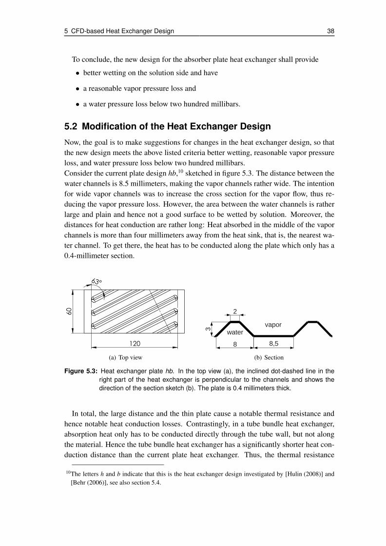
5 CFD-based Heat Exchanger Design 38
To conclude, the new design for the absorber plate heat exchanger shall provide
• better wetting on the solution side and have
• a reasonable vapor pressure loss and
• a water pressure loss below two hundred millibars.
5.2 Modification of the Heat Exchanger Design
Now, the goal is to make suggestions for changes in the heat exchanger design, so thatthe new design meets the above listed criteria better wetting, reasonable vapor pressureloss, and water pressure loss below two hundred millibars.Consider the current plate design hb,10 sketched in figure 5.3. The distance between thewater channels is 8.5 millimeters, making the vapor channels rather wide. The intentionfor wide vapor channels was to increase the cross section for the vapor flow, thus re-ducing the vapor pressure loss. However, the area between the water channels is ratherlarge and plain and hence not a good surface to be wetted by solution. Moreover, thedistances for heat conduction are rather long: Heat absorbed in the middle of the vaporchannels is more than four millimeters away from the heat sink, that is, the nearest wa-ter channel. To get there, the heat has to be conducted along the plate which only has a0.4-millimeter section.
60
63°
120
(a) Top view
2
8,58
3
vaporwater
(b) Section
Figure 5.3: Heat exchanger plate hb. In the top view (a), the inclined dot-dashed line in theright part of the heat exchanger is perpendicular to the channels and shows thedirection of the section sketch (b). The plate is 0.4 millimeters thick.
In total, the large distance and the thin plate cause a notable thermal resistance andhence notable heat conduction losses. Contrastingly, in a tube bundle heat exchanger,absorption heat only has to be conducted directly through the tube wall, but not alongthe material. Hence the tube bundle heat exchanger has a significantly shorter heat con-duction distance than the current plate heat exchanger. Thus, the thermal resistance
10The letters h and b indicate that this is the heat exchanger design investigated by [Hulin (2008)] and[Behr (2006)], see also section 5.4.

5 CFD-based Heat Exchanger Design 39
and hence the heat conduction losses in the plate heat exchanger are higher than in thetube bundle heat exchanger. Reducing the channel distance improves the plate heat ex-changer both as to heat conduction losses and as to surface wetting. In order to keep theincrease of vapor pressure loss moderate, we choose to reduce the channel distance toseven millimeters.
Now, the idea to improve wetting on the solution side is to create some kind of sub-structure between the water channels: water channels, smaller than the existing mainchannels. Let us call these smaller channels subchannels. See for example figure 5.4,depicting a plate with two subchannels per main channel. The subchannels divide theplanar surface between two adjacent main channels into several smaller surfaces andforce the solution flow to change its direction. Presumably, this diversification of thesurface on the vapor side improves wetting.Yet, subchannels have further advantages: First, they increase the plate’s surface area.An increased surface area means better heat exchange; more heat can be exchanged perplate (because Q = U · A · lmtd). In other words, the heat exchanger becomes morecompact because it needs fewer plates to exchange the required amount of heat. Theincreased surface area is a complement to the improved wetting, the latter resulting in amore efficient use of the available heat exchanger surface area.Another advantage: Subchannels reduce the heat conduction losses. The cooling waterflows not only in the main channels, but also in the subchannels. Consequently, theheat from absorption on or near the subchannels does not have to be conducted as far asto the next main channel but only to the subchannel. As a result, the average distancefor heat conduction from the solution to the cooling water decreases and so do the heatconduction losses; the efficiency of the heat exchanger increases.A drawback of subchannels is, however, that the subchannels reduce the cross section ofthe vapor channels; and so does the lower distance between the main channels. Hencethe vapor pressure loss increases. As mentioned above, not the vapor pressure loss butbad wetting is supposed to be the cause for the current heat exchanger’s poor perfor-mance. Certainly subchannels and narrower vapor channels increase the vapor pressureloss. We assume, however, that the positive impact of improved wetting and lower heatconduction losses by far outweighs increased vapor pressure losses. This assumptionstill is to be verified by, for instance, tests of a prototype or simulations. The presentwork, however, cannot cover that verification.Moreover, two further design changes can reduce the vapor pressure loss: First, asmaller plate width and second, a larger channel angle. The channel angle is the an-gle between the channel axis and the side edge of the plate. Both a smaller plate widthand a larger channel angle reduce the distance that the vapor has to cover from the edgeto the center of the absorber heat exchanger. As to wetting, a smaller channel angle isbetter than a larger, as [Behr (2006)] found in his wetting experiments. Nevertheless, amoderate increase of the channel angle will be considered.To sum up, we consider the following changes of the heat exchanger plate design:

5 CFD-based Heat Exchanger Design 40
• creation of smaller subchannels between the existing channels,
• reduction of the heat exchanger’s width, and
• increase of the channel angle.
5.3 CFD-Simulation as Evaluation Tool
In the previous subsections, we discussed the current design of the plate heat exchangerand suggestions to improve the heat exchanger’s performance. To get a more detailedidea of the positive or negative effects of the suggestions for an improved heat exchangerdesign, we need to quantify the effects of the design parameters in question. Therefore,we create a number of plate designs in which one or more of the suggested designchanges are implemented, see section 5.4. Comparing the different designs then allowsto more accurately evaluate the impact of the different changes. The criteria in thatcomparison are the heat transfer and the resulting capacity per volume, and the pressureloss on the water side.For conventional plate heat exchangers, that is, intermating and chevron corrugated plateheat exchangers with a uniform channel size and uniform channel distances, literatureoffers correlations to calculate the pressure loss and the heat transfer coefficient.11 Thus,engineers can estimate the performance of a new heat exchanger design quite comfort-ably. In our case however, the mentioned correlations are not or only partly valid. As[Hulin (2008)] did, we could with some approximations use the existing correlations forour designs without subchannels. The designs with subchannels however are certainlytoo different from the conventional designs and the respective correlations are not validfor them. Consequently, we do not consider this approach.Instead, we use Computational Fluid Dynamics (CFD).12 After designing the heat ex-changer plates with the commercial CAD program SolidWorks13, we analyze them withFlow Simulation, the CFD application within SolidWorks. Flow Simulation can calcu-late a great variety of flow problems. The user has to define the computational domainand the boundary conditions, can configure a number of settings like mesh generationor convergence criteria, and Flow Simulation then calculates the flow and the specifieddata like, for instance, pressure, temperature or velocity. As in other CFD applications,the post-processing of Flow Simulation also allows to visualize all calculated character-istics of the simulated flow problem in a number of ways.
11See for instance [Martin (2006)].12For more detailed information on CFD, see for instance [Versteeg & Malalasekera (1995)].13The used version is SolidWorks 2010.

5 CFD-based Heat Exchanger Design 41
5.4 Investigated Heat Exchanger Designs
This section presents the above mentioned plate designs that we simulate in order toevaluate the impact of the different design changes suggested in section 5.2. For all de-signs, a pair of the respective heat exchanger plates is assembled, so that the water sideis between the plates. Yet, the simulations do not calculate the entire plate pairs. See forexample figure 5.4, showing the isometric view of a simulated plate pair assembly. Onboth the top and the bottom side, the plates are canted. Thus, only a part of the plates isleft; the actual inlet and outlet openings and the distribution and collecting systems forthe fluids are cut away.
Figure 5.4: Isometric view of the simulated 2sub plate package
Why not simulate an entire plate package? First, a smaller computational domainallows more accurate results with the given, limited computing power. The mesh for thecalculation can be refined to better resolve the turbulent flow and in spite of the refinedmesh, the computing time is reasonable. Second, this study focusses on the patternof the heat exchanger plates, that is, the channel distance, the channel angle and thepresence of subchannels. The inlet and outlet region and the adjacent distribution andcollecting areas are only small compared to the rest of the plates. Hence, they only causea relatively small part of the pressure loss, as a prestudy confirmed. And moreover, thedistribution and collecting systems of the plates will be redesigned later anyway.14 Con-sequently considering the current ones in this study without comparing them with othersmakes only limited sense - especially as it would also require to coarsen the computa-tional mesh because of the limited computing power at our disposal and hence lead toless accurate results. In short, this CFD study aims at an improved channel structureand thus the simulations focus on the respective part of the plates.Back to figure 5.4. The water flows through the plate assembly in negative z-direction.Note the red faces in the front. They mark the inlet boundaries of the water. Here, thewater enters the plate assembly, flows through the channel pattern and exits at the outlet
14For reasons of time, the redesign of the inlet and outlet systems cannot be covered within this thesis.

5 CFD-based Heat Exchanger Design 42
boundaries on the back. Figure 5.5 gives an idea of what the flow through the plateassembly looks like.
Figure 5.5: Flow trajectory plot of the 2sub plate package
The following paragraphs briefly describe the main characteristics of the simulatedheat exchanger plates, which are listed in table 5.1. Note that the plate geometries serveto compare the impact of different design features based on the result of the CFD sim-ulations. They are, however, not intended as ready-to-manufacture designs. In fact,minor changes may be necessary before a heat exchanger design can be manufactured.
hb
The letters h and b, the initial letters of the names Hulin and Behr indicate that the firstplate design to be simulated is the design that was investigated by [Hulin (2008)] and[Behr (2006)]. Figure 5.3 shows the plate. The channels are eight millimeters wideand three millimeters high. The channel angle is 63 degrees, the channel distance is8.5 millimeters, and the heat exchanger width (that is, the horizontal dimension of thechannels, not the distance between the side edges of the plates) is 120 millimeters.
nosub63
The second plate design is depicted in figure 5.6. The term nosub in the name indicatesthat the plate does not have any subchannels. As for the hb-design, the channel angleis 63 degrees, indicated by the number 63 in the name. Yet, compared to the hb-designthe channel distance is reduced from 8.5 to seven millimeters, and the heat exchangerwidth from 120 to 106 millimeters.Note: The heat exchanger width of the following designs is not 106, but 100 millime-ters. However, those designs have another channel angle, 72.2 degrees. For a 72.2
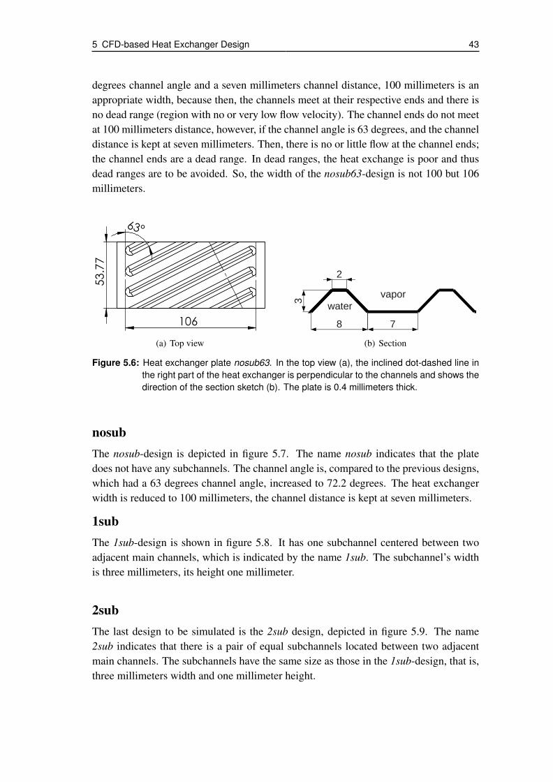
5 CFD-based Heat Exchanger Design 43
degrees channel angle and a seven millimeters channel distance, 100 millimeters is anappropriate width, because then, the channels meet at their respective ends and there isno dead range (region with no or very low flow velocity). The channel ends do not meetat 100 millimeters distance, however, if the channel angle is 63 degrees, and the channeldistance is kept at seven millimeters. Then, there is no or little flow at the channel ends;the channel ends are a dead range. In dead ranges, the heat exchange is poor and thusdead ranges are to be avoided. So, the width of the nosub63-design is not 100 but 106millimeters.
53.77
106
63°
(a) Top view
2
78
3vapor
water
(b) Section
Figure 5.6: Heat exchanger plate nosub63. In the top view (a), the inclined dot-dashed line inthe right part of the heat exchanger is perpendicular to the channels and shows thedirection of the section sketch (b). The plate is 0.4 millimeters thick.
nosubThe nosub-design is depicted in figure 5.7. The name nosub indicates that the platedoes not have any subchannels. The channel angle is, compared to the previous designs,which had a 63 degrees channel angle, increased to 72.2 degrees. The heat exchangerwidth is reduced to 100 millimeters, the channel distance is kept at seven millimeters.
1subThe 1sub-design is shown in figure 5.8. It has one subchannel centered between twoadjacent main channels, which is indicated by the name 1sub. The subchannel’s widthis three millimeters, its height one millimeter.
2subThe last design to be simulated is the 2sub design, depicted in figure 5.9. The name2sub indicates that there is a pair of equal subchannels located between two adjacentmain channels. The subchannels have the same size as those in the 1sub-design, that is,three millimeters width and one millimeter height.

5 CFD-based Heat Exchanger Design 44
57
100
72.2°
(a) Top view
2
78
3
vaporwater
(b) Section
Figure 5.7: Heat exchanger plate nosub. In the top view (a), the inclined dot-dashed line inthe right part of the heat exchanger is perpendicular to the channels and shows thedirection of the section sketch (b). The plate is 0.4 millimeters thick.
57
100
72.2°
(a) Top view
2
2
1
38
3
1
water
vapor
(b) Section
Figure 5.8: Heat exchanger plate 1sub. In the top view (a), the inclined dot-dashed line in theright part of the heat exchanger is perpendicular to the channels and shows thedirection of the section sketch (b). The plate is 0.4 millimeters thick.
57
100
72.2°
(a) Top view
2
0,3
1
30,4
8
3
1
water
vapor
(b) Section
Figure 5.9: Heat exchanger plate 2sub. In the top view (a), the inclined dot-dashed line in theright part of the heat exchanger is perpendicular to the channels and shows thedirection of the section sketch (b). The plate is 0.4 millimeters thick.
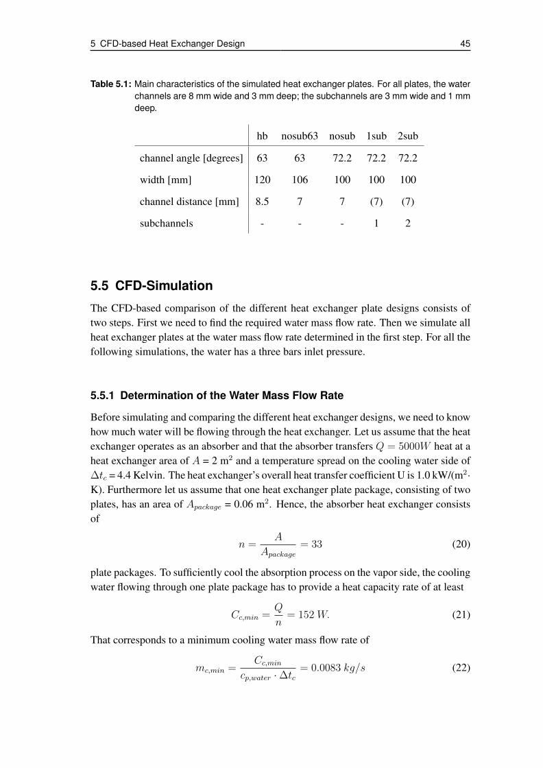
5 CFD-based Heat Exchanger Design 45
Table 5.1: Main characteristics of the simulated heat exchanger plates. For all plates, the waterchannels are 8 mm wide and 3 mm deep; the subchannels are 3 mm wide and 1 mmdeep.
hb nosub63 nosub 1sub 2sub
channel angle [degrees] 63 63 72.2 72.2 72.2
width [mm] 120 106 100 100 100
channel distance [mm] 8.5 7 7 (7) (7)
subchannels - - - 1 2
5.5 CFD-Simulation
The CFD-based comparison of the different heat exchanger plate designs consists oftwo steps. First we need to find the required water mass flow rate. Then we simulate allheat exchanger plates at the water mass flow rate determined in the first step. For all thefollowing simulations, the water has a three bars inlet pressure.
5.5.1 Determination of the Water Mass Flow Rate
Before simulating and comparing the different heat exchanger designs, we need to knowhow much water will be flowing through the heat exchanger. Let us assume that the heatexchanger operates as an absorber and that the absorber transfers Q = 5000W heat at aheat exchanger area of A = 2 m2 and a temperature spread on the cooling water side of∆tc = 4.4 Kelvin. The heat exchanger’s overall heat transfer coefficient U is 1.0 kW/(m2·K). Furthermore let us assume that one heat exchanger plate package, consisting of twoplates, has an area of Apackage = 0.06 m2. Hence, the absorber heat exchanger consistsof
n =A
Apackage
= 33 (20)
plate packages. To sufficiently cool the absorption process on the vapor side, the coolingwater flowing through one plate package has to provide a heat capacity rate of at least
Cc,min =Q
n= 152 W. (21)
That corresponds to a minimum cooling water mass flow rate of
mc,min =Cc,min
cp,water · ∆tc= 0.0083 kg/s (22)
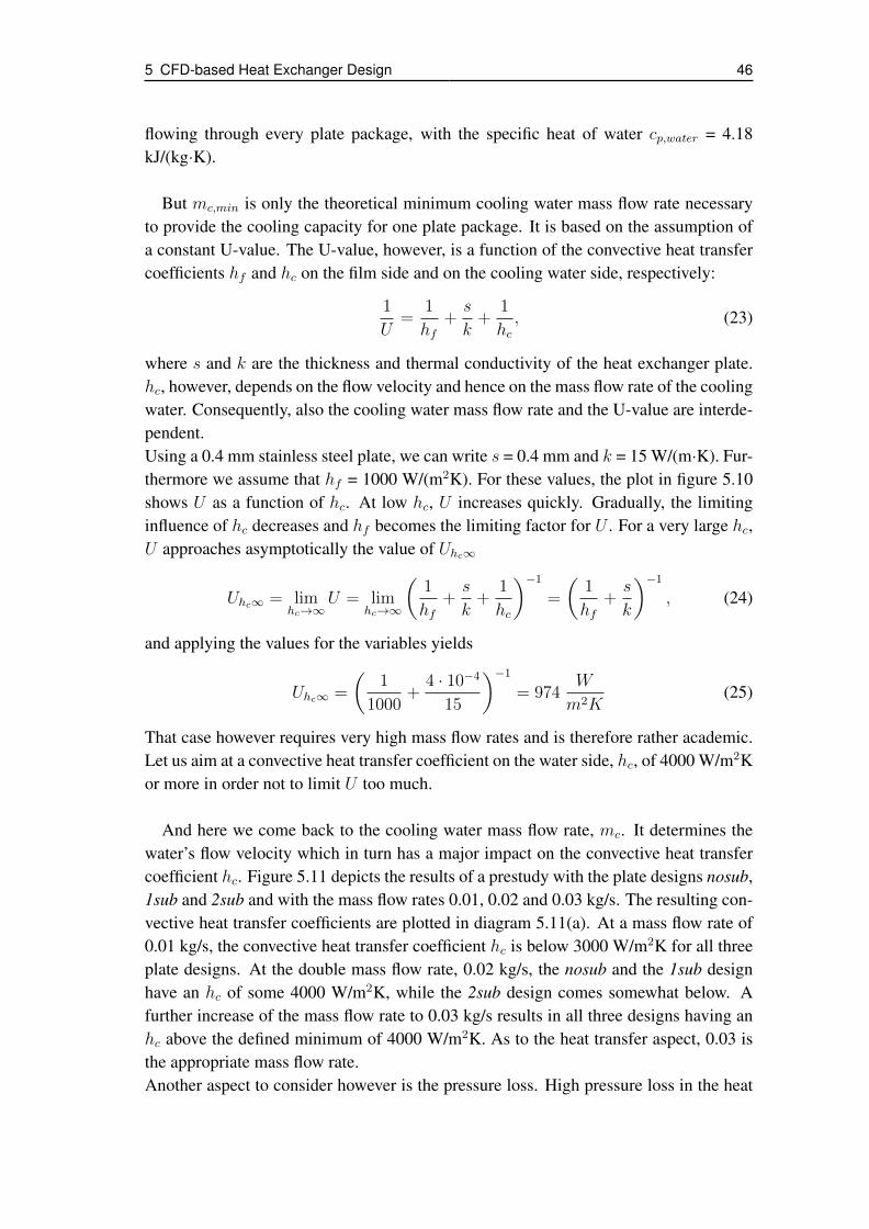
5 CFD-based Heat Exchanger Design 46
flowing through every plate package, with the specific heat of water cp,water = 4.18kJ/(kg·K).
But mc,min is only the theoretical minimum cooling water mass flow rate necessaryto provide the cooling capacity for one plate package. It is based on the assumption ofa constant U-value. The U-value, however, is a function of the convective heat transfercoefficients hf and hc on the film side and on the cooling water side, respectively:
1
U=
1
hf+s
k+
1
hc, (23)
where s and k are the thickness and thermal conductivity of the heat exchanger plate.hc, however, depends on the flow velocity and hence on the mass flow rate of the coolingwater. Consequently, also the cooling water mass flow rate and the U-value are interde-pendent.Using a 0.4 mm stainless steel plate, we can write s = 0.4 mm and k = 15 W/(m·K). Fur-thermore we assume that hf = 1000 W/(m2K). For these values, the plot in figure 5.10shows U as a function of hc. At low hc, U increases quickly. Gradually, the limitinginfluence of hc decreases and hf becomes the limiting factor for U . For a very large hc,U approaches asymptotically the value of Uhc∞
Uhc∞ = limhc→∞
U = limhc→∞
(1
hf+s
k+
1
hc
)−1=
(1
hf+s
k
)−1, (24)
and applying the values for the variables yields
Uhc∞ =
(1
1000+
4 · 10−4
15
)−1= 974
W
m2K(25)
That case however requires very high mass flow rates and is therefore rather academic.Let us aim at a convective heat transfer coefficient on the water side, hc, of 4000 W/m2Kor more in order not to limit U too much.
And here we come back to the cooling water mass flow rate, mc. It determines thewater’s flow velocity which in turn has a major impact on the convective heat transfercoefficient hc. Figure 5.11 depicts the results of a prestudy with the plate designs nosub,1sub and 2sub and with the mass flow rates 0.01, 0.02 and 0.03 kg/s. The resulting con-vective heat transfer coefficients are plotted in diagram 5.11(a). At a mass flow rate of0.01 kg/s, the convective heat transfer coefficient hc is below 3000 W/m2K for all threeplate designs. At the double mass flow rate, 0.02 kg/s, the nosub and the 1sub designhave an hc of some 4000 W/m2K, while the 2sub design comes somewhat below. Afurther increase of the mass flow rate to 0.03 kg/s results in all three designs having anhc above the defined minimum of 4000 W/m2K. As to the heat transfer aspect, 0.03 isthe appropriate mass flow rate.Another aspect to consider however is the pressure loss. High pressure loss in the heat
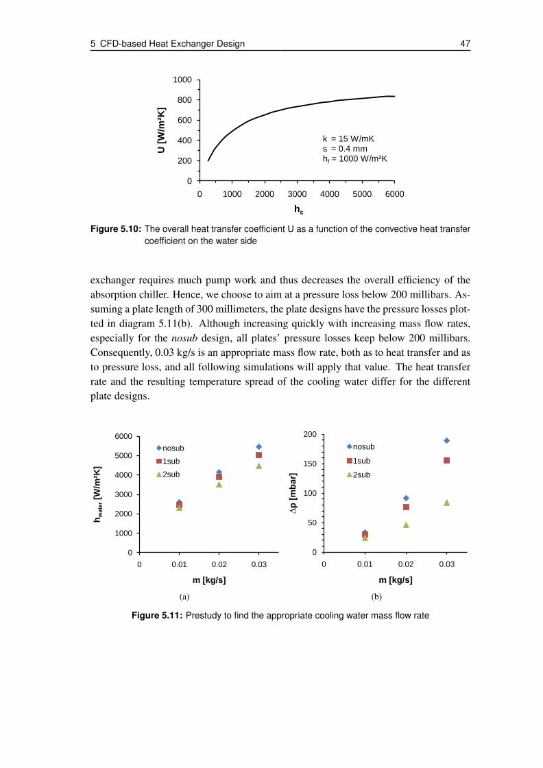
5 CFD-based Heat Exchanger Design 47
0
200
400
600
800
1000
0 1000 2000 3000 4000 5000 6000
U [
W/m
²K]
hc
k = 15 W/mKs = 0.4 mmhf = 1000 W/m²K
Figure 5.10: The overall heat transfer coefficient U as a function of the convective heat transfercoefficient on the water side
exchanger requires much pump work and thus decreases the overall efficiency of theabsorption chiller. Hence, we choose to aim at a pressure loss below 200 millibars. As-suming a plate length of 300 millimeters, the plate designs have the pressure losses plot-ted in diagram 5.11(b). Although increasing quickly with increasing mass flow rates,especially for the nosub design, all plates’ pressure losses keep below 200 millibars.Consequently, 0.03 kg/s is an appropriate mass flow rate, both as to heat transfer and asto pressure loss, and all following simulations will apply that value. The heat transferrate and the resulting temperature spread of the cooling water differ for the differentplate designs.
0
1000
2000
3000
4000
5000
6000
0 0.01 0.02 0.03
hw
ate
r[W
/m²K
]
m [kg/s]
nosub
1sub
2sub
(a)
0
50
100
150
200
0 0.01 0.02 0.03
∆p
[m
bar]
m [kg/s]
nosub
1sub
2sub
(b)
Figure 5.11: Prestudy to find the appropriate cooling water mass flow rate

5 CFD-based Heat Exchanger Design 48
5.5.2 Simulation Results
After having introduced the simulated heat exchanger plate designs and having deter-mined the necessary cooling water mass flow rate in the previous subsections, we canpresent and discuss the simulation results in this subsection. But before, let us mentionthe input data:The cooling water has an inlet temperature of 30 degrees Celsius and an inlet pressure ofthree bars, at a mass flow rate of 0.03 kilogram per second. As it will do in countercur-rent operation, the cooling water flows upwards - the CFD-model considers gravity. Onthe vapor side, the temperature is 40 degrees Celsius and the heat transfer coefficientbetween film and plate is assumed constant, 1000 W/m2K. The SolidWorks materialdatabase provides the thermal conductivity of the steel plate, which is 15 W/(m·K) forthe temperature range in our application.With that input data, the simulations yield the results presented on the following pages.First, consider the averaged conductive heat transfer coefficients in the water channelsof the different plates, shown in figure 5.12. As seen earlier, the designs with a 72.2 de-grees channel angle, namely the nosub, 1sub and 2sub designs, reach an hc of more than4000 W/m2K, with 1sub almost reaching 5000 and nosub even exceeding 5000 W/m2K.In contrast, the current hb design reaches only 4000 W/m2K and the nosub63 designslightly more. The latter values however still are sufficient - remember, the aimed con-vective heat transfer coefficient is 4000 W/m2K. So, as to the averaged convective heattransfer, all designs perform sufficiently. Yet the designs with a 72.2 degree channelangle have a somewhat better heat transfer coefficient.
0
1000
2000
3000
4000
5000
6000
hb nosub63 nosub 1sub 2sub
hw
ate
r[W
/m²K
]
Figure 5.12: Averaged convective heat transfer coefficients on the water side
[Behr (2006)] and [Hulin (2008)] also determined the heat transfer coefficient on thewater side of the hb heat exchanger. At a 0.03 kilogram per second water mass flowrate, Hulin found a heat transfer coefficient of 8000 W/(m2K), whereas Behr’s simula-tions at mc = 0.037 kg/s and his calculations at mc = 0.031 kg/s yielded 1360 and 3260W/(m2K), respectively. The discrepancy between Behr’s and Hulin’s values is signifi-cant. The result of our simulation of the hb heat exchanger, 4000 W/(m2K), is well in
5 CFD-based Heat Exchanger Design 49
the middle of Behr’s lower value and Hulin’s value, and close to Behr’s higher value.That points on a good feasibility of our value.
Let us now consider the temperature distribution on the vapor side for the respectiveplate designs, depicted in the figures 5.13-5.17. The plates without subchannels, thatis, the hb, nosub 63 and nosub design, figures 5.13-5.15, feature a regular pattern ofwarm spots between the channels. At these spots, the plates are in contact, and thus nocooling water is located between the plates. Consequently the heat absorbed here has tobe conducted to the nearest channel before it can be cooled by the water - other than atthe rest of the plate, where the heat only has to be conducted through the 0.4 millimeterplate. Because of that longer distance, the thermal resistance between film and coolingwater is larger and the temperature on the film side is higher in the respective areas.Thanks to the larger channel angle, the nosub plates’ contact areas causing the warmspots are somewhat smaller and the distance between them is larger. Hence also thewarm spots are smaller and the distance between them is larger compared to the two de-signs with the 63 degrees channel angle, hb and nosub63. Moreover the nosub63 plateshows smaller warm spots than the hb plate, because the channel distance is lower.Note that the temperature plots are not true to scale. As stated in section 5.4, the hb heatexchanger is 120 millimeters wide and the nosub63 heat exchanger is 106 millimeterswide, whereas the other heat exchangers are 100 millimeters wide. These differencesmay, if the beholder is not aware of them, lead to a somewhat wrong impression as tothe dimensions of, for instance, the warm spots.
Consider now the temperature plots of the plate pairs with subchannels, the 1sub andthe 2sub plate packages, shown in the figures 5.16 and 5.17. Here, the warm spots be-tween the channels observed at the previous designs are not present. The temperaturedifferences on the plates are much lower - disregarded the warm edges outside the actualheat exchanger area, where no water channels are present. Obviously the subchannelssignificantly enhance the plate cooling. Now the warmest spots are located at the inter-sections of the main channels.The reason for that new location of the warmest spots can be found in the different con-vective heat transfer coefficients in the main channels and subchannels. The convectiveheat transfer coefficients given in figure 5.12 are averaged values. For the 1sub and 2subplates however, there are considerable differences between the heat transfer coefficientsin the main channels and in the subchannels: The 1sub plate shows an averaged con-vective heat transfer coefficient of 4400 W/m2K in the main channels and 6000 W/m2Kin the subchannels, the respective values for the 2sub plate are 4000 and 5500 W/m2K.Hence, the cooling in the subchannels is more effective than in the main channels andthus the coldest spots are located on the subchannels whereas the warmest spots arelocated on the main channels. But again, the temperature differences between the coldand the warm spots are comparably low.

5 CFD-based Heat Exchanger Design 50
Figure 5.13: Temperature plot of the film side of the hb plate
Figure 5.14: Temperature plot of the film side of the nosub63 plate
Figure 5.15: Temperature plot of the film side of the nosub plate
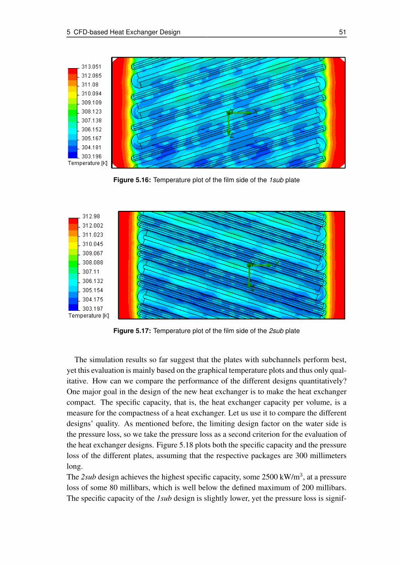
5 CFD-based Heat Exchanger Design 51
Figure 5.16: Temperature plot of the film side of the 1sub plate
Figure 5.17: Temperature plot of the film side of the 2sub plate
The simulation results so far suggest that the plates with subchannels perform best,yet this evaluation is mainly based on the graphical temperature plots and thus only qual-itative. How can we compare the performance of the different designs quantitatively?One major goal in the design of the new heat exchanger is to make the heat exchangercompact. The specific capacity, that is, the heat exchanger capacity per volume, is ameasure for the compactness of a heat exchanger. Let us use it to compare the differentdesigns’ quality. As mentioned before, the limiting design factor on the water side isthe pressure loss, so we take the pressure loss as a second criterion for the evaluation ofthe heat exchanger designs. Figure 5.18 plots both the specific capacity and the pressureloss of the different plates, assuming that the respective packages are 300 millimeterslong.The 2sub design achieves the highest specific capacity, some 2500 kW/m3, at a pressureloss of some 80 millibars, which is well below the defined maximum of 200 millibars.The specific capacity of the 1sub design is slightly lower, yet the pressure loss is signif-

5 CFD-based Heat Exchanger Design 52
0
50
100
150
200
0
500
1000
1500
2000
2500
3000
hb nosub63 nosub 1sub 2sub
∆p
[m
bar]
sp
ecif
ic c
ap
ac
ity [
kW
/m³]
specific capacity
pressure loss
Figure 5.18: Specific capacity and pressure loss of the simulated heat exchanger plates
icantly higher, some 155 millibars - below the 200 millibar limit, however. The nosubdesign has again a somewhat lower specific capacity and a significantly higher pressureloss, just below the 200 millibar limit. Better than the nosub design is the nosub63design. Its specific capacity is merely slightly higher, but its pressure loss is only some-what above 50 millibars and hence the lowest of all five designs. The current platedesign, the hb design, has the lowest specific capacity - it is the only plate below 2000kW/m3 - but also has a pressure loss below 60 millibars.[Behr (2006)] and [Hulin (2008)] determined the pressure loss of the entire hb heat ex-changer with a 337 millimeter length, also considering the cooling water inlet and outletopenings. Hulin measured a 44 millibar pressure loss at a 0.03 kilogram per second wa-ter mass flow rate, Behr simulated at a 0.037 kilogram per second water mass flow rateand found a 48 millibar pressure loss. Our simulations yield a pressure loss below 60millibars for a 300 millimeter long hb heat exchanger package and is hence moderatelyhigher than Behr’s and Hulin’s results.
5.5.3 Conclusions from the Simulation Results
The results of the CFD-simulations show that different modifications can enhance thespecific capacity of the current plate heat exchanger, the hb design.The nosub63 design is slightly more compact than the hb design. The main reason forthat is the lower channel distance. First, the lower channel distance results in smallerwarm spots on the film side. Second, it increases the heat exchanger area. Third, itreduces the distance between the channel intersections, where turbulence increases be-cause the two intersecting flows have different flow directions. And increased turbulencemeans increased heat transfer.In spite, the nosub63 heat exchanger has a slightly lower pressure loss than the hb heatexchanger. As the cross sectional area for the flow is equal for the two designs, the lowerpressure loss of the nosub63 design is due to the lower width of the heat exchanger and

5 CFD-based Heat Exchanger Design 53
the resulting shorter distance that the cooling water flows in average. The pressure losshowever refers to a 300 millimeter-long plate package and as the nosub63 plate is nar-rower than the hb plate, its heat exchanger area per length is lower. These aspects shouldbe considered when comparing the pressure losses. Nevertheless, the difference of thetwo designs in terms of pressure loss is so small that it is negligible in praxis.Assumed that the slightly narrower vapor channels do not affect the vapor flow note-worthy and thus outweigh the advantage of the enhanced cooling, the nosub63 heatexchanger will perform slightly better than the hb heat exchanger. That means, a slightreduction of the channel distance improves the heat exchanger performance.
A comparison of the nosub63 design with the nosub design shows that a mere in-crease of the channel angle is counterproductive as far as the water side is concerned.The specific capacity of the nosub heat exchanger is virtually equal to that of the no-sub63 heat exchanger, yet the pressure loss is more than three times higher. Using thenosub design instead of the nosub63 design only makes sense if the larger channel angleimproves wetting on the vapor side, which in turn increases the absorber performance.Then the increased performance justifies the higher pressure loss of the cooling water,which still is below the defined maximum of 200 millibars.
Other than increasing the channel angle, using heat exchanger plates with subchan-nels both increases the specific capacity and decreases the cooling water pressure loss.The 1sub plate is equal to the nosub plate, yet additionally it has a subchannel betweenthe main channels. This subchannel enhances the specific capacity of the heat exchangerby more than ten percent and reduces the pressure loss by more than ten percent.Using two subchannels brings a further increase of the specific heat exchanger capacityto 2550 kW/m3. That means a 35 percent increase compared to the hb design and a 21percent increase compared to the nosub design. The pressure loss is 55 percent higherthan for the hb design but 44 percent lower than for the nosub design and hence farbelow the 200 millibar.To sum up, subchannels improve the heat transfer and thus the specific capacity of theabsorber significantly. They can even compensate for part of the additional pressure lossdue to a larger channel angle. Moreover we can expect better wetting on the solutionside because of the more sophisticated texture. The somewhat reduced cross section forthe vapor flow will not degrade the overall improvements notably.

6 Summary
The present work contributes to the design of a new low-scale absorption chiller basedon plate heat exchangers and focuses on improving the plate heat exchanger design. Toa minor extent, it covers cycle design. At a capacity of four kilowatts, the planned ex-ternal temperatures of the absorption chiller are 15/10 degrees Celsius for the chilledwater, 30/38 degrees for the cooling water and 90/80 degrees for the hot water.
Integration is a promising approach for an inexpensive and compact heat exchangerdesign. First, the solution distribution system can be integrated into the plate structure ofthe heat exchanger. Second, the walls of the pressure vessel around the heat exchangercan be integrated into the heat exchanger plates. Thus, the heat exchanger forms itsown vessel and does no longer need a separate one. Third, two heat exchangers can beintegrated on one plate.The latter demands that the heat exchangers be pairwise equal. In contrast to an in-dividual optimization of the heat exchanger areas, an absorption chiller with pairwiseequal heat exchangers has a larger overall heat exchanger area. Cycle calculations show,however, that this effect is moderate. The benefit resulting from, among others, reducedmanufacture cost, prevails.
Insufficient wetting causes the poor performance of the current heat exchanger pro-totype when used as absorber. To enhance the solution mass flow rate and thus wetting,two recirculation concepts for the absorber are of interest: Recirculation with mixture inthe sump (sump recirculation) and recirculation with mixture before the absorber (mixedrecirculation). According to cycle calculations, both concepts perform similarly. Mixedrecirculation is slightly better as to heat exchanger area and COP, yet sump recirculationis easier to carry out and hence the preferable concept.To overcome poor wetting at the generator, a thinkable approach is pool boiling. But theresults of the respective cycle calculations indicate that a pool generator does not workwith the planned external temperatures. To operate a pool generator, at least one of theexternal temperature levels needs to be adopted - a compromise is to be found.
As to the heat exchanger, three design changes are considered: First, creation ofsmaller subchannels between the existing channels to enhance wetting, second, reduc-tion of the heat exchanger width to reduce the vapor pressure loss, and third, increase ofthe channel angle, also to reduce the vapor pressure loss.A CFD-based comparison of five design variants gives information on the impact ofdifferent plate design changes. As could be expected, the heat exchanger width haslittle impact on the water side. At a constant water mass flow rate, a lower heat ex-changer width causes a faster water flow and thus enhances the heat transfer slightly.
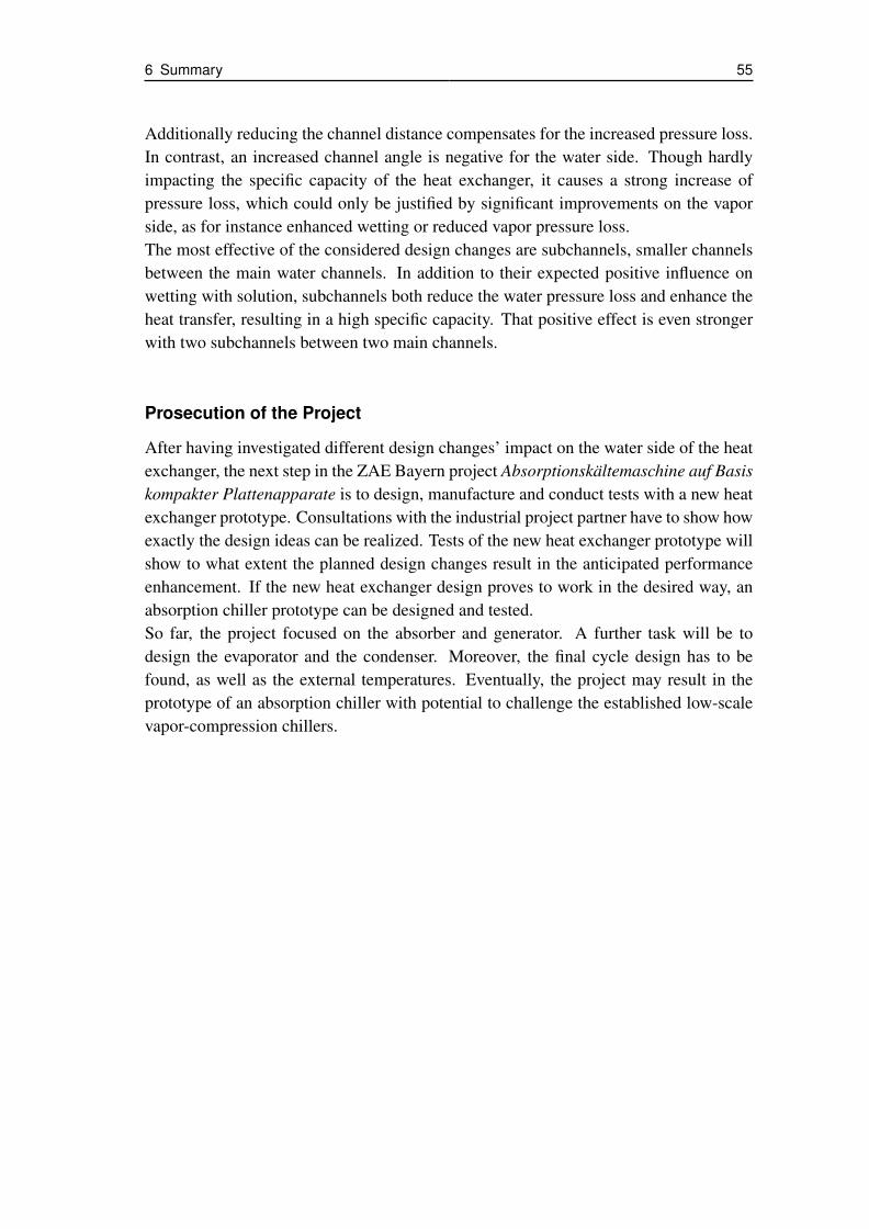
6 Summary 55
Additionally reducing the channel distance compensates for the increased pressure loss.In contrast, an increased channel angle is negative for the water side. Though hardlyimpacting the specific capacity of the heat exchanger, it causes a strong increase ofpressure loss, which could only be justified by significant improvements on the vaporside, as for instance enhanced wetting or reduced vapor pressure loss.The most effective of the considered design changes are subchannels, smaller channelsbetween the main water channels. In addition to their expected positive influence onwetting with solution, subchannels both reduce the water pressure loss and enhance theheat transfer, resulting in a high specific capacity. That positive effect is even strongerwith two subchannels between two main channels.
Prosecution of the Project
After having investigated different design changes’ impact on the water side of the heatexchanger, the next step in the ZAE Bayern project Absorptionskältemaschine auf Basiskompakter Plattenapparate is to design, manufacture and conduct tests with a new heatexchanger prototype. Consultations with the industrial project partner have to show howexactly the design ideas can be realized. Tests of the new heat exchanger prototype willshow to what extent the planned design changes result in the anticipated performanceenhancement. If the new heat exchanger design proves to work in the desired way, anabsorption chiller prototype can be designed and tested.So far, the project focused on the absorber and generator. A further task will be todesign the evaporator and the condenser. Moreover, the final cycle design has to befound, as well as the external temperatures. Eventually, the project may result in theprototype of an absorption chiller with potential to challenge the established low-scalevapor-compression chillers.
References 56
References
[Alefeld & Radermacher (1993)] G. Alefeld, R. Radermacher: Heat ConversionSystems. ISBN 0-8493-8928-3, CRC Press, BocaRaton 1993.
[Alfa Laval (2004)] Alfa Laval: Brazed heat exchangers. A productcatalogue for refrigeration.http://www.alfalaval.com/solution-finder/products/ac-series/pages/documentation.aspx?Source=http%3a%2f%2fwww.alfalaval.com%2fsolution-finder%2fproducts%2fpages%2fdefault.aspx%3ftype%3dProductCategory%26firstItemID%3d54e32261-aa20-4f0f-9851-344c49bf67b7(accessed on May/13/2011).
[Behr (2006)] C. Behr: Wärme- und Stoffübertragung an einemAbsorber in Plattenwärmeübertrager-Ausführungeiner Absorptionskältemaschine. Diploma thesis,Fachhochschule München, Munich 2006.
[Beil (2011)] A. Beil: Entwicklung eines Teststandes zur Un-tersuchung neuartiger Plattenwärmetauscher alsHauptkomponenten für Absorptionskältemaschi-nen. Bachelor thesis, Fachhochschule Deggendorf,Munich 2011.
[Bethge & Wüst (2007)] P. Bethge, C. Wüst: Zeit für eine Revolution. DERSPIEGEL 7/2007, ISSN 0038-7452, SPIEGEL-Verlag Rudolf Augstein, Hamburg 2007.
[Clausen (2007)] J. Clausen: Zukunftsmarkt Solares Kühlen.Fallstudie im Auftrag des Umweltbundesamtesim Rahmen des Forschungsprojektes InnovativeUmweltpolitik in wichtigen Handlungsfeldern,Förderkennzeichen 206 14 132/05. Borderstep In-stitut, ISSN 1865-0538, Karlsruhe 2007.
[Estiot et al. (2007)] E. Estiot, S. Natzer, C. Schweigler: Heat Ex-changer Development for Compact Water/LiBr Ab-sorption Systems. Proceedings of the 22nd IIRInternational Congress of Refrigeration, Beijing2007.

References 57
[Estiot (2009)] E. Estiot: Behältersieden von wässriger Lithi-umbromidlösung - Untersuchung zur Entwicklungkompakter Absorptionskältemaschinen. PhD the-sis, Technische Universität München, ISBN 978-3-86853-385-9, Verlag Dr. Hut, Munich 2009.
[Gorenflo (2006)] D. Gorenflo: Behältersieden (Sieden bei freierKonvektion). VDI-Wämeatlas, 10. Auflage.Verein Deutscher Ingenieure, Springer-Verlag,Berlin/Heidelberg 2006. Chapter Hab.3.
[Herold et al. (1996)] K.E. Herold, R. Radermacher, S.A. Klein: Ab-sorption Chillers and Heat Pumps. ISBN 0-8493-9427-9, CRC Press, Boca Raton 1996.
[Höges (1997)] V. Höges: Klimatisierter Alptraum. Wie sich dieAmerikaner bemühen, die größten Energiever-schwender der Welt zu bleiben. DER SPIEGEL49/1997, ISSN 0038-7452, SPIEGEL-VerlagRudolf Augstein, Hamburg 1997.
[Hulin (2008)] S. Hulin: Wärmeübertragung und Druckverlusteines Plattenwärmetauschers für eine Absorption-skältemaschine. Diploma thesis, Technische Uni-versität München, Munich 2008.
[Joudi & Lafta (2000)] K.A. Joudi, A.H.Lafta: Simulation of a simple ab-sorption refrigeration system. Energy Conversionand Management, Vol.42, pp. 1575-1605, 2001.
[Jung (2007)] A. Jung: Why Conservation Is the World’s Best En-ergy Source. SPIEGEL ONLINE, November 2007.http://www.spiegel.de/international/world/0,1518,476231,00.html (accessed on May/7/2010).
[Kaji et al. (1995)] M. Kaji, M.Furukawa, T. Suyama, K.Sekoguchi: Enhancement of Pool Boiling HeatTransfer to Lithium Bromide Aqueous Solution.Technology Reports of the Osaka University,Vol.45, pp.49-58, April 1995.
[Kommer & Hinz (2010)] C. Kommer, C. Hinz: DSW-Datenreport2010. Soziale und demographische Daten zurWeltbevölkerung. Deutsche Stiftung für Welt-bevölkerung, ISBN 3-930406-10-1, Hannover2010.

References 58
[Lee et al. (1991)] C.C. Lee, Y.K. Chuah, D.C. Lu, H.Y. Chao: Ex-perimental investigation of Pool Boiling of LithiumBromide Solution on a Vertical Tube under Sub-atmospheric Pressures. International Communica-tions in Heat and Mass Transfer, Vol.18, pp. 309-320, 1991.
[Martin (2006)] H. Martin: Druckverlust und Wärmeübergangin Plattenwärmeübertragern. VDI-Wärmeatlas,zehnte Auflage, Springer-Verlag, Berlin Heidelberg2006.
[Natzer et al. (2010)] S. Natzer, M. Walch, C. Schweigler: Unter-stützung von trockener Rückkühlung: Vorkühleffektbei Installation in Tiefgeschossen. Deutsche Kälte-Klima Tagung, Magdeburg 2010.
[Parsons & Forman (1989)] R.A. Parsons, C. Forman: ASHRAE Handbookof Fundamentals. ISBN 0-9101-1056-5, AmericanSociety of Heating, Refrigerating and Air Condi-tioning Engineers, Inc., 1989.
[Plura (2008)] S. Plura: Entwicklung einer zweistufigen Absorp-tionkältemaschine zur effizienten Kraft-Wärme-Kältekopplung. PhD thesis, Technische UniversitätMünchen, Munich 2008.
[Riesch (1991)] P. Riesch: Wärmetransformatoren mit hohem Tem-peraturhub. PhD thesis, Technische UniversitätMünchen, Munich 1991.
[Schweigler (1999)] C. Schweigler: Kälte aus Fernwärme - Konzept,Auslegung und Betrieb der Single-Effect/Double-Lift-Absorptionskälteanlage. Fortschritt-BerichteVDI, Reihe 19, Nr. 121, ISBN 3-18-312119-0, VDIVerlag, Düsseldorf 1999.
[Uemura & Hasaba (1964)] T. Uemura, S. Hasaba: Studies on the lithiumbromide-water absorption refrigeration machine.Technology reports of Kansai University, Vol.6, pp.31-55, 1964.
[Versteeg & Malalasekera (1995)] H.K. Versteeg, W. Malalasekera: An introduc-tion to Computational Fluid Dynamics - The Finite

References 59
Volume Method. ISBN 978-0-582-21884-0, Pear-son Education Limited, Essex 1995.
[Wuschig (2007)] C. Wuschig: Modellierung und Bewertung vonangepassten zwei-/einstufigen LiBr/H2O - Absorp-tionsmaschinen. Diploma thesis, Technische Uni-versität München, Munich 2007.
[Wuschig et al. (2009)] C. Wuschig, S. Plura, C. Schweigler: Opti-mierung von Absorptionskältemaschinen. KI KälteLuft Klimatechnik, pp. 28-33, July/August 2009.

A Solution Mass Flow Rate for Good Wetting
Good wetting is crucial for an absorber to perform well. [Beil (2011)] conductedwetting tests with a plastic model plate pair of the current plate heat exchanger, the hbdesign. He found that aqueous lithium-bromide solution starts to wet the surface at aminimum volume flow rate of 0.15 liters per minute. Good wetting requires 0.4 litersper minute. To assure that the volume flow rate is sufficient for complete wetting, let usassume a volume flow rate of V̇ = 0.5 liters per minute or 8.333 · 10−3 liters per second,respectively.The plates are 356 millimeters high and 120 millimeters wide, so the approximate sur-face area of one plate is
Ap ≈ 0.356 m · 0.120 m = 4.272 · 10−2 m2. (26)
Consisting of two plates, the package area to be wetted is
Aw = 2 · Ap = 8.544 · 10−2 m2. (27)
With the aqueous lithium-bromide solution’s density ρ = 1.5 kilogram per liter, therequired mass flow rate writes
m = V̇ · ρ = 8.333 · 10−3l
s· 1.5
kg
l= 1.25
kg
s. (28)
Finally, dividing the required mass flow rate with the wetted area yields the specificmass flow rate
m
Aw
=1.25kg
s
8.544 · 10−2 m2= 0.146
kg
m2s. (29)
The cycle calculations considering solution recirculation at the absorber - see chapter 4- prescribe that value to justify the assumption of complete wetting. For different platedimensions or a different heat exchanger pattern, respectively, the required specific massflow rate will differ.