development of nanocrystalline fe cr … bahan adalah sesuai pada komposisi 20.05 wt% cr and 79.95...
TRANSCRIPT

DEVELOPMENT OF NANOCRYSTALLINE Fe80Cr20 ALLOY USING
COMBINATION TECHNIQUE OF BALL MILLING AND
ULTRASONIC TREATMENT FOR FUEL CELL
INTERCONNECTOR
DAFIT FERIYANTO
A thesis submitted in fulfillment of the requirement for the award of the
Degree of Master of Mechanical Engineering
Faculty of Mechanical and Manufacturing Engineering
Universiti Tun Hussein Onn Malaysia
December 2014

v
ABSTRACT
Solid Oxide Fuel Cell (SOFC) system consists of anode, cathode, electrolyte and
interconnect. This research is focused on interconnect material. The objective of this
study is to explore the high energy ball milling (milled) combined with ultrasonic
treatment (UT) in obtaining smaller crystallite size, finer surface morphology, higher
thermal stability and more homogenous nanocrystalline Fe80Cr20 alloys. This
condition was motivated by the previous research that some of the grain growth was
observed in a high temperature. At first, this process was carried out by high energy
ball milling with milling time of 60 h and later, the samples experienced the
ultrasonic treatment with frequency of 35 kHz at various periods of 3 h, 3.5 h, 4 h,
4.5 h, and 5 h. Moreover, it was found that there are no works on these combination
treatments (milled and UT). Characterization and analysis were carried out to all
samples by using X-Ray Diffraction (XRD), Scanning Electron Microscope (SEM)
and Energy dispersive X-ray Diffraction (EDS), Thermo Gravimetric Analysis
(TGA) and Particle Size Analyzer (PSA). The results showed that the combination
treatment samples increases effectively to the solid solubility of Cr to Fe up to 62.1%
and decreased the crystallite size up to 2.71 nm at milled and UT 4.5 h sample, these
resulted and produces finer surface structure. From EDS results, the combination
treatment samples are at suitable composition of 20.05 wt% Cr and 79.95 wt% Fe as
compared to other samples. Higher thermal stability was observed on combination
treatment sample at 1100 0C up to 12.7 mg or convenient to 63 wt%, 62 wt% and 25
wt% as compared to raw material, UT samples and milled 60 h sample, respectively.
The particle size decreased up to 5.23 µm and particle size distribution of
combination treatment relatively increased up to 89.57%. It can be concluded that the
combination treatment at milled and UT 4.5 h is appropriate to achieve high solid
solubility, nano crystallite size, fine surface morphology, high thermal stability and
homogenous Fe80Cr20 alloys.

vi
ABSTRAK
Sistem sel fuel oksida pepejal (SOFC) terdiri daripada anod, katod, elektrolit dan plat
penyambung. Perkara utama yang ditekankan dalam kajian ini ialah bahan plat
penyambung yang digunakan. Objektif kajian ini adalah untuk memperoleh saiz
hablur Fe80Cr20 yang lebih kecil, permukaan morfologi yang lebih halus, kestabilan
terma yang lebih tinggi serta mempunyai nano hablur yang lebih seragam dengan
menggunakan mesin bebola pengisar yang digabungkan dengan rawatan ultrasonik.
Kaedah ini berdasarkan kajian lepas yang menunjukkan pertumbuhan butiran berlaku
pada suhu tinggi. Pada mulanya, proses dimulakan dengan mengisar bahan dengan
meggunakan bebola pengisar bertenaga tinggi dalam tempoh 60 jam. Kemudian
bahan diberi rawatan ultrasonik dengan frekuensi 35 kHz pada tempoh yang berbeza
iaitu 3, 3.5, 4, 4.5 dan 5 jam. Tambahan lagi, sebelum ini tiada kajian yang
menggunakan teknik gabungan antara pengisaran dan rawatan ultrasonik. Perincian
dan analisis bahan diperolehi menggunakan belauan sinar X (XRD), mikroskop
imbasan elektron (SEM), tenaga serakan belauan sinar X (EDS), analisis gravimetrik
terma (TGA) dan penganalisis saiz zarah (PSA). Keputusan menunjukkan kaedah
penggabungan teknik pengisar dan UT 4.5 jam meningkatkan kelarutan pepejal Cr ke
Fe sehingga 62.1 %, mengurangkan saiz hablur sehingga 2.71 nm dan menghasilkan
struktur permukaan yang lebih halus. Keputusan daripada EDS, penggabungan
rawatan bahan adalah sesuai pada komposisi 20.05 wt% Cr and 79.95 wt% Fe
berbanding dengan sampel lain. Penggabungan rawatan bahan pada suhu 1100 0C
mempunyai penambahan berat 12.7 mg yang menunjukkan ketahanan panas yang
tinggi berbanding dengan bahan mentah, UT dan pengisar 60 jam menunjukkan
pengurangan berat sebanyak 63 wt%, 62 wt% and 25 wt%. Penggabungan rawatan
mengurangkan saiz partikel sehingga 5.23 µm dan pengagihan saiz meningkat secara
relatif sehingga 89.57%. Secara kesimpulannya penggabungan rawatan pengisar and
UT 4.5 jam adalah yang paling sesuai untuk mendapatkan kelarutan pepejal yang
tinggi, saiz nano hablur, permukaan morfologi yang halus, kestabilan terma yang
tinggi serta mempunyai nano hablur yang seragam.

vii
TABLE OF CONTENT
TITLE i
DECLARATION ii
DEDICATION iii
ACKNOWLEDGMENT iv
ABSTRACT v
TABLE OF CONTENT vii
LIST OF TABLES xi
LIST OF FIGURES xiii
LIST OF SYMBOLS AND ABBREVIATION xvi
CHAPTER 1 INTRODUCTION
1.1 Research background 1
1.2 Problem statement 3
1.3 Hypothesis 4
1.4 Research objectives 5
1.5 Scope of study 5
CHAPTER 2 LITERATURE REVIEW
2.1 Introduction of SOFC 7
2.1.1 SOFC Material 8
2.1.2 Crystal structure for solid oxide fuel cell (SOFC) 9
2.1.3 Operating Principle of SOFC 10
2.1.4 SOFC component 12
2.1.4.1 Anode 12
2.1.4.2 Cathode 13
2.1.4.3 Electrolyte 15

viii
2.1.4.4 Interconnect 17
2.2 Oxidation of metallic alloy 18
2.3 Metallic interconnect 20
2.3.1 Chromium based alloys 22
2.3.2 Iron based alloys 24
2.3.3 Iron-Chromium Alloys 25
2.4 Mechanical alloying 27
2.4.1 Control agent in ball milling process 29
2.4.2 Temperature of ball milling 30
2.4.3 Temperature increase during ball milling process 31
2.4.4 Ball milling mechanism 32
2.4.5 Ductile-ductile Fe and Cr sample 34
2.4.6 Solid solubility 35
2.5 Nanocrystalline 37
2.6 Effect of crystallite size 39
2.7 Determining crystallite size 40
2.7.1 Measuring interplanar spacing and lattice parameter 41
2.7.2 Measuring solid solubility (Xss) 43
2.7.3 Measuring Bcorrected 43
2.7.4 Measuring crystallite size and strain of the material 45
2.8 Particle size and distribution 47
2.9 Ultrasonic treatment 48
2.9.1 Maximizing the cavitations 51
2.9.2 Mechanism of ultrasonic treatment 51
2.9.3 Broader application area for ultrasonic treatment 52
2.10 Summary of literature review 53
CHAPTER 3 METHODOLOGY
3.1 Sample designation 55
3.2 Flow chart 56
3.3 Starting material 58

ix
3.4 Powder blending 58
3.5 Ultrasonic treatment 62
3.6 Combination technique 64
3.7 Characterization and analysis 65
3.7.1 X-Ray diffraction analysis 65
3.7.2 Morphology characterization 66
3.7.3 Thermal analysis 67
3.7.4 Determining particle size and distribution 67
CHAPTER 4 RESULT AND DISCUSSION
4.1 XRD pattern analysis 69
4.1.1 XRD pattern of raw material (Fe80Cr20) 70
4.1.2 XRD pattern of the ultrasonic treatment (UT)
samples and raw material
71
4.1.3 XRD peaks of the milled 60 h and combination
technique (milled and UT) Samples
73
4.1.4 Comparison XRD pattern of treated and untreated
samples
75
4.2 Determining crystallite size using Williamson-Hall method 76
4.2.1 Crystallite size and strain of the raw material and
the ultrasonic (UT) samples
77
4.2.2 Crystallite size and strain of the milled 60 h and
combination technique (milled and UT) samples
79
4.2.3 Comparison of crystallite size and strain of treated
and untreated samples
82
4.3 The relation between lattice parameter and the solid
solubility (Xss)
85
4.4 Surface morphology of the treated and untreated samples 87
4.4.1 Surface Morphology of Cr and Fe powder as raw
materials
88
4.4.2 Surface morphology of ultrasonic treatment (UT)

x
samples 89
4.4.3 Surface morphology of milled 60 h and
combination technique(milled and UT) samples
90
4.5 Identification of the chemical composition 93
4.6 Determining the thermal stability 95
4.6.1 Thermal stability of the UT samples 96
4.6.2 Thermal stability of the milled 60 h samples and
combination technique samples
97
4.6.3 Comparison thermal stability of treated and
untreated samples
100
4.7 Particle size and distribution of the treated and untreated
samples
102
4.8 Summaries 104
CHAPTER 5 CONCULSIONS AND RECOMMENDATIONS
5.1 Conclusions 106
5.2 Recommendations 107
REFERENCE 109
APPENDIX A XRD analysis 122
APPENDIX B SEM analysis 135

xi
LIST TABLES
Table No. Item Page
Table 2.1 Type of material SOFC components within several operation
temperatures
8
Table 2.2 Atomic radius and crystal structures for 16 metals 10
Table 2.3 Advantages and disadvantages of several type anode materials 12
Table 2.4 Advantages and disadvantages of several type cathode materials 14
Table 2.5 Advantages and disadvantages of several type electrolyte
materials
16
Table 2.6 Advantages and disadvantages of several types interconnect
materials
17
Table 2.7 Varies metallic candidate materials for interconnect application 21
Table 2.8 Material properties of chromium powder 23
Table 2.9 Material properties of iron powder 24
Table 2.10 Temperature rise during ball milling process 32
Table 3.1 Samples designation 56
Table 3.2 Detail information of raw material 58
Table 3.3 Various diameter and amount of ball mill 59
Table 3.4 Technical data of ultrasonic bath machine 63
Table 4.1 XRD data of the Fe80Cr20 alloys powders 70
Table 4.2 Result of XRD analysis of the treated and untreated samples 76
Table 4.3 Crystallite size and strain of the sample with ultrasonic treatment 78

xii
Table 4.4 Crystallite size and strain of the Fe80Cr20, milled 60 h and
combination technique
80
Table 4.5 Comparison crystallite sizes of the milled 60 h sample and
combination technique samples
81
Table 4.6 Crystallite size and strain of the treated and untreated samples 83
Table 4.7 Comparison crystallite size of the treated and untreated samples 84
Table 4.8 The solid solubility (xss) of Cr into Fe 86
Table 4.9 TGA data of the treated and untreated samples 100
Table 4.10 Comparison mass gain of the treated and untreated samples 101
Table 4.11 Particle size and distribution of the treated and untreated samples 102
Table 4.12 Comparison particle size of the treated and untreated samples 104
Table 4.13 The correlation of the all results 104

xiii
LIST OF FIGURES
Figure No. Item Page
Figure 2.1 Configuration for planar design SOFC 8
Figure 2.2 Unit cell of crystal structure 9
Figure 2.3 Operating Concept of a SOFC 11
Figure 2.4 Anode with Ni-YSZ material 13
Figure 2.5 Cathode with LaMnO3 material 14
Figure 2.6 Temperature dependence of conductivity for undoped and Sr-
dopend LaMnO3
15
Figure 2.7 TGA oxidation curve 19
Figure 2.8 Phase diagram of Fe-Cr system 26
Figure 2.9 Oxidation in air of a Fe 26 wt% Cr 1 wt% Mo alloy 27
Figure 2.10 Grain size vs milling time for CoZr 31
Figure 2.11 Collision of the powder when mixture during mechanical
alloying
33
Figure 2.12 Particle size distribution at various ball milling times under
steady-state conditions
33
Figure 2.13 Refinement of particle and grain sizes with milling time 34
Figure 2.14 Deformation characteristic of starting powder in ball milling
process
35
Figure 2.15 Schematic diagram of solid solubility vs milling 35
Figure 2.16 Solid solubility of Fe in Cu 36
Figure 2.17 Classification of nanocrystalline materials 37
Figure 2.18 Volume fractions of the crystallite, grain boundary, triple line
and quadruple node as a function of crystallite size
38
Figure 2.19 Grain size and hardness of a ball milled Fe20Cr alloy versus
annealing time at 6000C
40
Figure 2.20 X-Ray Diffraction 42

xiv
Figure 2.21 FWHM of the standard reference material for LaB6 on an in-
house Cu K diffractometer
44
Figure 2.22 Principle of the laser diffraction 47
Figure 2.23 Schematic of particle size analyzer 48
Figure 2.24 Sound frequency ranges 49
Figure 2.25 Microscopy analysis of FeCrY2O3 alloy by SEM treated by
ultrasonic with frequency 22 kHz and holding time of 2.5 h
50
Figure 2.26 Eutectic silicon morphology of a AlSi9Cu3: (a) non-US treated
and (b) US treated at 400 W and 615 0C melt temperature
53
Figure 3.1 Flow chart of the research works 57
Figure 3.2 Various size of ball mill media 59
Figure 3.3 The grinding jar 60
Figure 3.4 Glove box 60
Figure 3.5 RETCH PM 400 planetary ball mill 61
Figure 3.6 Schematic depicting of the ball motion inside ball milling
machine
61
Figure 3.7 Schematic diagram of ultrasonic treatment 62
Figure 3.8 Fe and Cr powder before XRD process 65
Figure 3.9 Fe and Cr powder for SEM preparation 66
Figure 3.10 CILAS 1180 particle size Analyzer (PSA) 68
Figure 3.11 Schematic diagram of CILAS 1180 particle size analyzer work 68
Figure 4.1 Planes crystal structure of Fe80Cr20 69
Figure 4.2 XRD peaks of the Fe80Cr20 alloys powders 70
Figure 4.3 XRD peaks of the raw material and UT treatment samples 72
Figure 4.4 XRD peaks of the raw material, milled 60 h sample and
combination technique (milled and UT) samples
74
Figure 4.5 XRD pattern of the treated and untreated samples 75
Figure 4.6 Crystallite size vs strain of the raw material and UT treatment
samples
79
Figure 4.7 Crystallite size vs strain of the milled 60 h and combination

xv
technique samples 81
Figure 4.8 Effect of strain on the diffraction peaks and crystallite size 82
Figure 4.9 Crystallite size and lattice parameter of treated and untreated
samples
83
Figure 4.10 Crystallite size and strain of treated and untreated samples 84
Figure 4.11 Lattice parameter vs solid solubility of the treated and untreated
samples
86
Figure 4.12 SEM morphology images of the raw material 88
Figure 4.13 Surface morphology of a); Ultrasonic treatment 3 h; b):
Ultrasonic treatment 3.5 h; c): Ultrasonic treatment 4 h; d):
Ultrasonic treatment 4.5 h; e): Ultrasonic treatment 5 h
89
Figure 4.14 Surface morphology of a); milled 60 h; b) milled and UT 3 h;
c): milled and UT 3.5 h; d): milled and UT 4 h; e): milled and
UT 4.5 h; f): milled and UT 5 h
91
Figure 4.15 EDS result of Fe80Cr20 alloy powder 93
Figure 4.16 EDS result of UT 4.5 h 94
Figure 4.17 EDS result of Milled 60 h 94
Figure 4.18 EDS result of milled and UT 4.5 h 94
Figure 4.19 Mass gain result of the raw material and UT samples 96
Figure 4.20 Mass change derivative of the raw material and UT treatment
samples
97
Figure 4.21 Mass gains of the milled 60 h sample and combination
technique samples
98
Figure 4.22 Mass change derivative of the raw material and UT treatment
samples
99
Figure 4.23 Mass gain vs crystallite size of the treated and untreated
samples
101
Figure 4.24 Particle size vs distribution size of the treated and untreated
samples
103

xvi
LIST OF SYMBOLSAND ABBREVIATION
SOFC - Solid Oxide Fuel Cell
SOx - Sulfur Oxide
NOx - Nitrogen Oxide
CO2 - Carbon Dioxide
CO - Carbon Monoxide
CH4 - Methane
rad - radian
H2 - Hydogen
µm - Micrometer (10-6
meter)
nm - Nanometer (10-9
meter)
h - Hours
YSZ - Yttrium Stabilized Zirconia
LaMnO3 - Lanthanum Manganite
Ni - Nickel
H2O - Air
Fe - Iron
FeO - Iron Oxide
Cr - Chromium
Fe-Cr - Iron Chromium
Cr2O3 - Chromium Oxide
BCC - Body Centered Cubic
FCC - Face Centered Cubic
HCP - Hexagonal Close-Packed
Å - Angstrom
D - The diameter crystallite size (nm).
k - The shape factor (k=0.9).
- Wavelength of the X-Ray ( =0.154056 nm for Cu-K ).

xvii
- Bragg diffraction angle.
B - The broadening of the diffraction peaks measured at half of its
maximum intensity (in radians).
Bcorrected - The instrumental corrected Full Width at Half Maximum
(FWHM) in radians
Bobs - The Full Width at Half Maximum (FWHM) from diffraction
peak of the specimens
Binstrument - Standard peaks of the standard reference materials
- The strain present in the material
d - Interplanar spacing (Å)
a - Lattice parameter
Xss - Solid Solubility (%)
WD - Work Distance (mm)
kV - Kilo Volt
mm - Millimeter
kHz - Kilo Hertz
SPS800 - Spark Plasma Sintering at 800 0C
UTHM - University Tun Hussein Onn Malaysia
TGA - Thermo Gravimetric Analysis
EDS - Energy Dispersive X-Ray Diffraction
PSA - Particle Size Analyzer
FeCrAl - Iron Chromium Aluminum
Fe80Cr20 - Composition of alloy powder with 80 wt% Fe and 20 wt% Cr
UT - Ultrasonic Treatment
Milled - Ball milling technique
Milled and UT - Combination technique ( Ball milling 60 h and ultrasonic
treatment)
MA - Mechanical Alloying
XRD - X-Ray Diffraction
SEM - Scanning Electron Microscopy
PCA - Process Control Agent
xviii
CTE - Coefficient of Thermal Expansion
LaCrO3 - Lanthanum Chromites
LPG - Liquefied Petroleum gas
INCO - International Nickel Company
HVOF - High Velocity Oxy-Fuel
YSZ - YttriaStabilizedZirconia
SCZ - Scandia Stabilized Zirconia
LSGM - Lanthanum Strontium Gallium Magnesium
CGO - Cerium Gadolinium Oxide
LSM - Lanthanum Strontium Manganite
LSCF - La0.6Sr0.4Co0.2Fe0.8O3
Ni-YSZ - Nickel-Yttria Stabilized Zirconia
Ni-SDC - Nickel-Samaria Doped Ceria
LCR - Lanthanum Chromites/LaCrO3
RSP - Rapid Solidification Processing
CCD - Charged Coupled Device
DSP - Digital Signal Processor
APU - Auxiliary Power Units
S/cm - Siemens per centimetre

CHAPTER 1
INTRODUCTION
This chapter consists of the research background, problem statement, hypothesis,
research objectives and scope of study.
1.1 Research Background
Solid Oxide Fuel Cells (SOFC) research develop most interest currentlyas its
potential to create an efficient system, high energy-density power generation device
which typically operates at high temperatures relatively (≅1000 0C). Nowadays,
research in SOFC focuses on the interconnect material because it must be stable
chemically in both of anode and cathode at temperature approximately 10000C
(Zhang, 2006 and Zhong et al., 2004), as well as grain growth on that temperature
was observed by Saryanto et al., (2009); Pudji et al.,(2009); Darwin et al.,(2010a)
and Deni (2011). The interconnect is required to connect thermally the different cells
and also providesthe physical barriers to keep the oxidant and fuel separated
(Yaodong et al., 2007). Metallic interconnect has interest material to promote as
interconnect because their high thermal conductivities (Deni, 2011 and Khaerudini et
al., 2012). In the current research, there is high interest in nanocrystalline iron and
chromium based alloys. The iron-chromium system has long been used by many
engineering alloys as the basis in high-strength and corrosion-resistant applications
such as for fuel cell interconnect. Traditionally, iron-based alloy with additions of
chromium has been used in high temperature (up to 10000C) applications (Basu,
2007), where the stabilization and oxidation behavior at high temperature are
fundamental in actual applications. Chromium has a phase stabilizer when added into
the iron. It is because the chromium has the same BCC crystal structure with iron and

2
made primarily to promote the formation of a dense, adherent layer of Cr2O3 on the
surface of the alloy (Craig, 1995).
Developing Fe80Cr20 based alloy using mechanical alloying via high energy
ball milling was successfully carried out by Saryanto et al., (2009). Mechanical
alloying (MA) are in general micro and nano structured often have remarkable
properties. The product depends on many parameters such as the milling conditions,
amount material which are being processed, type of the ball mill used and milling
time (Suryanarayana, 2001 and Suryanarayana, 2004). Mechanical alloying
technique is able to synthesize single-phase FeT (T = Cr, Cu and Ni) binary alloys
with average crystalline size below 50 nm and exhibiting a variety of magnetic
responses (Martinez-Blanco et al., 2011). Therefore, it is very challenging to develop
nanocrystalline FeCr alloy, because the Cr metal encourage the formation of
protective oxide (scale) (Quadakkers et al., 2003). Nanoscale particle research has
become a very important field in materials science recently. A nanocrystalline
material was characterized by a microstructural length scale in 1 to 100 nm range
(Koch, 2003). Nano powders or nano materials with physical, chemical, and the
mechanical properties can be utilized as the main building of innovative solutions for
the problems in energy, environment, health and communication (Ozlem et al.,
2012). Nanoscale particles usually have different physical properties compared with
large particles. It had been found that nanoparticles exhibit variety of previously
unavailable properties including magnetic, optical, and other physical properties as
well as the surface reactivity depending on particle size (Poole et al., 2003).
Therefore, heat-resistant nanoscale particle alloys is produced in the industrial scale
and widely used in different fields of science and technology.
In the area of ultrasonic processing in liquid media, the development of the
power generators family with extensive radiators has strongly contributed to the
implementation at semi-industrial and industrial stage of several commercial
applications. Some of the applications are in food industry, environment and process
for manufacturing (Juan et al., 2010). The use of high-intensity ultrasonic enhances
the reactivity of metals as stoichiometric reagents becamean important synthetic
technique for many heterogeneous organic and organometallic reactions, especially
for the involving reactive metals. In particular for small matter from several
nanometers on couple of microns, ultrasonic is very effective in breaking
agglomerates, aggregates and even primaries (Thomas et al., 2006; Pudji et al., 2009;

3
Krisztian et al., 2010 and Darwin et al., 2010b). The mechanism of the rate
enhancements in reactions of metals had been done by monitoring the effect of
ultrasonic vibration on the kinetics of chemical reactivity of solids, examining the
effects of vibration on the surface morphology and size distributions of powders
(Suslick, 1994; Kenneth et al., 1999; Pudji et al., 2009 and Darwin et al., 2010b).
Ultrasonic treatment also effectively refines the surface morphology on FeCrAl
substrate (Yanuandri, 2011 and Ade, 2012).However, the exploration and
improvement novel processes enhance the reducing of finer crystallite size and
homogenous distribution crystalline size of iron-chromium is still very challenging.
Many researchers field investigate the nano material using ball milling and
ultrasonic treatment in mixing raw material (Suryanarayana, 2001and Quadakkers et
al., 2003; Suryanarayana, 2004; Saryanto et al., 2009; Pudji et al., 2009; Darwin et
al., 2010a; Ade, 2012 and Ozlem et al., 2012). However, unsatisfactory performance
still resulted when applied at high temperature operation such as grain growth, rough
surface morphology, high oxidation, and the composition not appropriate with
working composition. No studies have yet been done on using combination
technique between ball milling and ultrasonic treatment. This study focus on the
development of iron-chromium alloy powder promoted using combination technique
in order to achieve smaller crystallite size, finer the surface morphology, more
homogenous and better thermal stability of Fe80Cr20 alloys powder.
1.2 Problem statement
The challenge in this research is how to produce the nano range crystallite size, finer
surface morphology, high thermal stability and homogenize powders size. Ball
milling process is significant to reduce the crystallite size into nano range size.
Nevertheless, processing techniques involves high-temperature conditions at longer
processing times cause the growth rate of crystallite size inevitable (Suryanarayana,
2001; Suryanarayana, 2003; Quadakkers et al.,2003 and Suryanarayana, 2004). In
previous research, grain growth from 5.82 nm to 38.51 nm occurred (Hendi, 2011and
Deni, 2011). Meanwhile, Ultrasonic process with fixed frequency develop and

4
achieve homogenous and fine grain structure alloys powder (Suslick, 1988; Kenneth
et al.,1999; Mikko et al., 2004; Thomas Hielscher, 2005; Darwin et al., 2010b; Ade,
2012 and Pudji et al., 2009). According toYanuandri, (2011) and Ade, (2012), the
frequency was conducted in 18.52 kHz and holding time of 10, 20, and 30 minutes
which were obtained the rough surface and less homogenous. Nanoscale material
have many advantages whencompared with large particle. It was proved by Hendi
(2011) and Deni (2011) that the cracks in commercial ferritic steel observed after
consolidated process at temperature of 900 0C. It means that large particle have low
thermodynamic stability when consolidated at temperature of 900 0C and above.
Therefore, the combination technique of ball milling and untrasonic treatment is
needed to obtain smaller grain size, finer surface morphology and more homogenous
crystallite sizes in nano range size.
1.3 Hypothesis
The hypothesis consider in this research are:
1. Ball milling will be effective to reduce the powder size into nanometer range
size.
2. Ultrasonic treatment will be improved the homogeneity and finer surface of
morphology.
3. Combination technique of ball milling and ultrasonic will be developed new
Fe80Cr20 alloy powder which have smaller crystallite size, more homogenous,
finer surface morphology and higher thermal stability.

5
1.4 Research objectives
Researchobjectives in this study are:
i. To develop nanostructured Fe80Cr20 alloy by using ultrasonic treatment, ball
milling and combination technique (milled combined with ultrasonic
treatment).
ii. To investigate the influence of different ultrasonic treatment time on particle
size and particle distribution.
iii. To investigate the influence of combination technique (milled combined with
ultrasonic) on powder size, homogeneity, fine surface morphology and
thermal stability.
1.5 Scope of study
The scopes of this research are:
1. Raw material is arranged by 80 wt% Fe, and 20 wt% Cr.
2. Developing the nanocrystalline Fe80Cr20 alloy is conducted by using ball
milling with milling time of 60 h. According to Hendi (2011), that the milling
time of 60 h is the most effective to develop nanocrystalline Fe80Cr20 alloy as
compared to higher milling time of 80 h.
3. Only nitrogen gas is used in high energy ball milling process
4. Ultrasonic process is introduced at appropriate frequency of 35 kHz and
holding times of 3 h, 3.5 h, 4 h, 4.5 h and 5 h.
5. The atmospheric pressure while ultrasonic treatment, characterization and
analysis process is assumed 1 atm.
6. The microstructure is observed by using Scanning Electron Microscopy
(SEM) and the composition of the individual particle is analyzed by using
Energy Dispersive X-Ray Spectroscopy (EDS).
7. Phase analyses is conducted by using X-Ray Diffraction (XRD).

6
8. Thermal analysis is conducted by using Thermo Gravimetric analysis (TGA)
up temperature of 1100 0C which are carried out to the all samples (treated
and untreated samples).
9. Determination of particle size and its distribution of particle size is done by
using Particle Size Analyzer (PSA).

CHAPTER 2
LITERATURE REVIEW
This literature related to this research is discussed in this chapter. It consists of the
theory about Solid Oxide Fuel Cell (SOFC), interconnect, developing nanocystalline
material, homogenizing, and refining the surface morphology.
2.1 Introduction of SOFC
According to Zhang (2006), Solid Oxide Fuel Cell (SOFC) is a promising technology
for electricity generation. It converts the chemical energy of the fuel gas to electrical
energy directly. Therefore, the electrical efficiencies can be achieved through this
system. The system can reach efficiency approximately 80% (efficiency of internal
combustion engine is no more 40%) when couple it with heat recovering system for
cogeneration (heating applications and electric power). Besides, SOFC can replace
several fuels and widely implemented to power supplies from small-scale
distribution power supplies to large-scale thermal power generation (Blein, 2005).

8
2.1.1 SOFC Material
The structure of SOFC is well stacked which consists of anode, electrolyte, cathode,
and interconnect materials as in Figure 2.1 (Quadakkers, 2003). Besides, the material
properties for SOFC component in various temperatures are tabulated in Table 2.1.
Figure 2.1 Configuration for planar design SOFC (Singhal, 2000 and Quadakkers,
2003)
There are many types of materials for SOFC components which are applied
by researcher to develop the efficient SOFC system. The most commonly material
which are used in the SOFC components and it is depend on the temperature
application as listed in the Table 2.1:
Table 2.1 Type of material SOFC components within several operation temperatures
(Rajendra, 2007)
SOFC operating
temperature
(0C)
Material
Cell
design
Electrolyte
thickness
(µm)
Electrolyte
Cathode
Anode
Interconnect
950-1000 YSZ LSM Ni-YSZ LCR Tubular 40
Planar 150-300
650-800 YSZ, SCZ LSM Ni-YSZ Ferritic steel Planar 5-20
400-650
LSGM,
CGO
LSCF
Ni-SDC
Ferritic steel Planar 500 or less
Stainless steel Planar 5 (LSGM)
Stainless steel Planar 10-30 (CGO)
Cell
Repeat
Unit
Current flow
Fuel
Interconnect
Electrolyte
Anode
Cathode
Air
interconnect

9
2.1.2 Crystal structure for solid oxide fuel cell (SOFC)
A crystalline material is one of atoms which are situated in a repeating or periodic
array over large atomic distances. Long-range crystal is observed after consolidation
the atoms. It will position itself in a repetitive three-dimensional pattern (Figure 2.2).
All metals, many ceramic materials, and certain polymers form crystalline structures
under normal solidification conditions (Smith, 2004).
Some of the properties of crystalline solids depend on the crystal structure of
the material, the manner in which atoms, ions, or molecules are arranged spatially.
The crystal structure has various structures from simple structure to complex
structure. A unit cell is chosen to represent the symmetry of the crystal structure;
where all of atom positions in the crystal may be generated by translations of the unit
cell integral distances along each its edges. Thus, the unit cell is the basic structural
unit or building block of the crystal structure and defines the crystal structure by
virtue of its geometry and the atom inside positions (Smith, 2004).
Figure 2.2 Unit cell of crystal structure (Smith, 2004)
Study of structural, electronic and magnetic behaviour of CuxFeCr1−xO2 has
been investigated by Osman (2013), they found that the partial crystal structure
deformation from delafossite CrFeO2 structure to corundum-type FeCrO3 structure is
contain CrO2 and Cr2O3 blocks. The crystal geometry is change when the Cr
substitution is increased. Therefore, the FeCr based alloys is used in this research in
order to minimize the change of crystal geometry.

10
Three simple crystal structures relatively are found for the most common
metals which are listed in Table 2.2: Face Centered Cubic (FCC), Body-Centered
Cubic (BCC) and Hexagonal Close-Packed (HCP).
Table 2.2 Atomic radius and crystal structures for 16 metals (Smith, 2004)
Metal Crystal
structurea
Atomic radiusb
(nm)
Metal Crystal
structure
Atomic
radius(nm)
Aluminium FCC 0.1431 Molybdenum BCC 0.1363
Cadmium HCP 0.1490 Nickel FCC 0.1246
Chromium BCC 0.1249 Platinum FCC 0.1387
Cobalt HCP 0.1253 Silver FCC 0.1445
Copper FCC 0.1278 Tantalum BCC 0.1430
Gold FCC 0.1442 Titanium (α) HCP 0.1445
Iron (α) BCC 0.1241 Tungsten BCC 0.1371
Lead FCC 0.1750 Zinc HCP 0.1332
aFCC (Face-Centred Cubic); HCP (Hexagonal Close-Packed); BCC (Body-Centred
Cubic).
bA nanometer (nm) equals 10
-9 m; to convert from nanometer to Angstrom units (Å),
multiply the nanometer value by 10.
2.1.3 Operating Principle of SOFC
The cell is constructed with two porous electrodes with an electrolyte in the middle.
Initially, the catalytically reaction can be described as follows, oxygen flows along
cathode in order to contact among cathode and electrolyte interface for importing the
ion oxygen to electrolyte and pass it towards anode. That reaction produces the
water, carbon dioxide, heat, and the electrons (Gorte et al., 2003). However, the
electron flow will occur when the electrical connection between the cathode and the
anode emerged, where a continuous supply of oxygen ions (O2-
) generated from
cathode to anode in order to maintain the overall electrical charge balance.
Ultimately, this process produced the residual product pure water (H2O) and heat.
The operating of SOFC technology is shown in Figure 2.3.
11
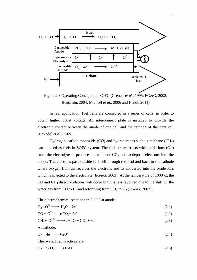
Figure 2.3 Operating Concept of a SOFC (Greneir et al., 1995; EG&G, 2002;
Benjamin, 2004; Michael et al., 2006 and Hendi, 2011)
In real application, fuel cells are connected in a series of cells, in order to
obtain higher outlet voltage. An interconnect plate is installed to provide the
electronic contact between the anode of one cell and the cathode of the next cell
(Navadol et al., 2009).
Hydrogen, carbon monoxide (CO) and hydrocarbons such as methane (CH4)
can be used as fuels in SOFC system. The fuel stream reacts with oxide ions (O2-
)
from the electrolyte to produce the water or CO2 and to deposit electrons into the
anode. The electrons pass outside fuel cell through the load and back to the cathode
where oxygen from air receives the electrons and its converted into the oxide ions
which is injected to the electrolyte (EG&G, 2002). At the temperature of 10000C, the
CO and CH4 direct oxidation will occur but it is less favoured due to the shift of the
water gas from CO to H2 and reforming from CH4 to H2 (EG&G, 2002).
The electrochemical reactions in SOFC at anode:
H2+ O2-
H2O + 2e- (2.1)
CO + O2-
CO2+ 2e-
(2.2)
CH4+ 4O2-
2H2 O + CO2 + 8e- (2.3)
At cathode:
O2 + 4e- 2O
2 (2.4)
The overall cell reactions are:
H2 + ½ O2 H2O (2.5)
e-
e-
Permeable
Cathode
impermeable
Electrolyte
Permeable
Anode
Oxidant
Fuel
H2 + CO H2O + CO2
2H2 + 2O2-
4e- + 2H2O
O2-
O2-
O2-
O2 + 4e- 2O
2-
H2 + CO
Air Depleted O2
heat
12
CO + ½O2 CO2 (2.6)
CH4+ 2O2 2H2O + CO2 (2.7)
2.1.4 SOFC Components
There are several components in SOFC system such as anode, cathode, electrolyte,
and interconnect. All the components are described as follows:
2.1.4.1 Anode
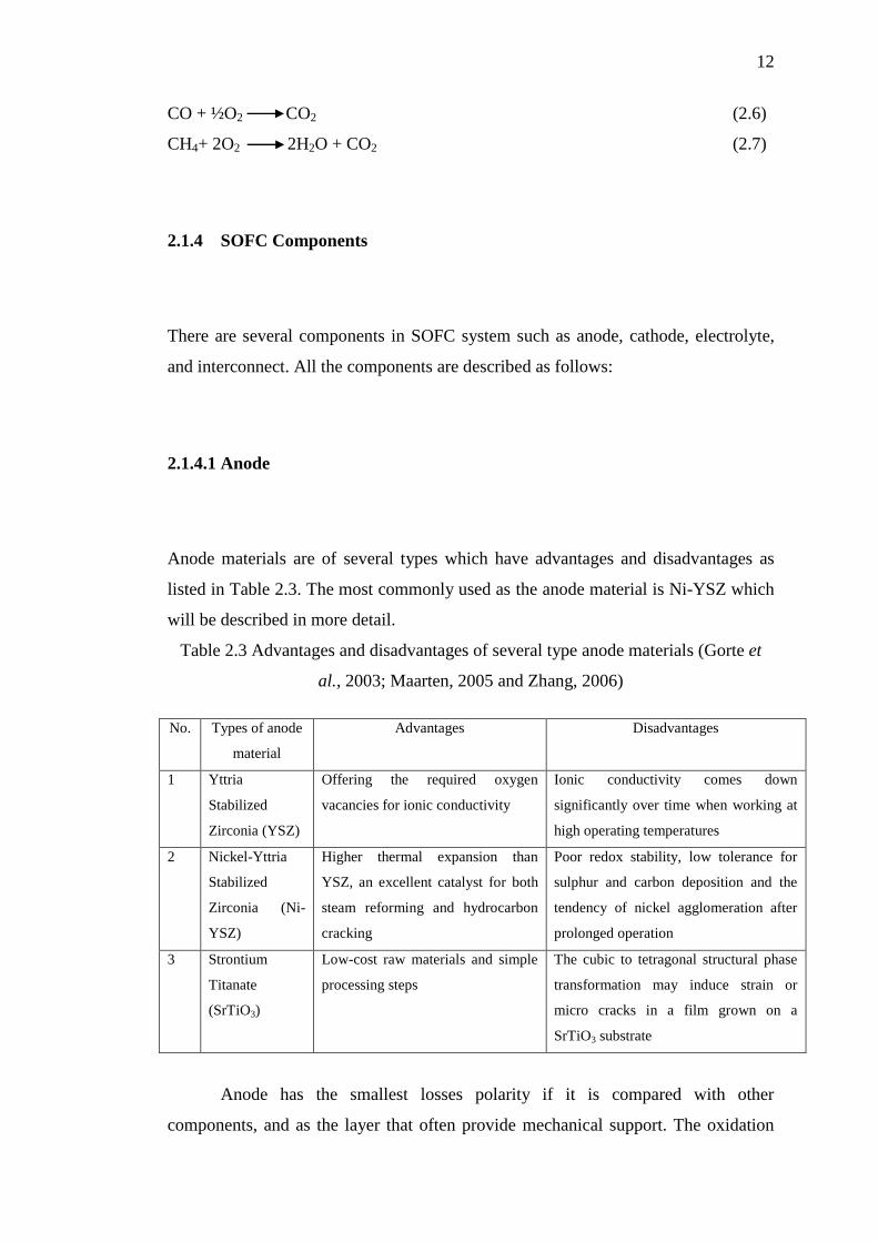
Anode materials are of several types which have advantages and disadvantages as
listed in Table 2.3. The most commonly used as the anode material is Ni-YSZ which
will be described in more detail.
Table 2.3 Advantages and disadvantages of several type anode materials (Gorte et
al., 2003; Maarten, 2005 and Zhang, 2006)
No. Types of anode
material
Advantages Disadvantages
1 Yttria
Stabilized
Zirconia (YSZ)
Offering the required oxygen
vacancies for ionic conductivity
Ionic conductivity comes down
significantly over time when working at
high operating temperatures
2 Nickel-Yttria
Stabilized
Zirconia (Ni-
YSZ)
Higher thermal expansion than
YSZ, an excellent catalyst for both
steam reforming and hydrocarbon
cracking
Poor redox stability, low tolerance for
sulphur and carbon deposition and the
tendency of nickel agglomeration after
prolonged operation
3 Strontium
Titanate
(SrTiO3)
Low-cost raw materials and simple
processing steps
The cubic to tetragonal structural phase
transformation may induce strain or
micro cracks in a film grown on a
SrTiO3 substrate
Anode has the smallest losses polarity if it is compared with other
components, and as the layer that often provide mechanical support. The oxidation

13
reaction between the oxygen and the hydrogen ions produces heat and water as well
as electricity. One of the advantages of anode as the catalyst for steam reformer
hydrocarbon gas becomes hydrogen fuel. It provide another operational benefit to the
fuel cell stack due to the reforming cools stack reaction internally (EG&G, 2002).
Therefore, its material should be catalytic, conductive, as well as porous to hydrogen
fuel. It may reduce the atmosphere and the thermal expansion must be compatible
with the other cell. Ni-YSZ anode is currently the material of choice for anode
material as shown in Figure 2.4 (Singhal, 2000).
Figure 2.4 Anode with Ni-YSZ material (Singhal, 2000)
Ni has a higher thermal expansion than YSZ (13.3 x 10⁻⁶
/0C for Ni and 10 x
10-6
/0C for YSZ). Therefore, the Ni-YSZ composite was created. This is due to the
YSZ that provide structural support for the separate Ni particles, preventing them
from sintering together while matching thermal expansion. The adhesion of the
anode to the electrolyte also increased (Singhal, 2003 and Zhong et al., 2004).
2.1.4.2 Cathode
Several advantages and disadvantages of the cathode materials were observed by
many engineers with different cathode materials are listed in Table 2.4. Generally,
LSM is used as the cathode material.
Ni-
YSZ
i> 0
e-
e-

14
Table 2.4 Advantages and disadvantages of several type cathode materials (Chunwen
et al., 2010 and Hyo et al., 2009)
No. Types of cathode
material
Advantages Disadvantages
1 Lanthanum
Strontium
Manganite (LSM)
High electrical conductivity at higher
temperatures, and its high thermal
expansion coefficient
Increasing costs and longer
start-up times
2 Lanthanum
Strontium Gallium
Magnesium
(LSGM)
High conducting properties at
intermediate operating temperatures
while providing stability
High thermal expansion
The most commonly used cathode material is lanthanum manganite
(LaMnO3) as shown in Figure 2.5. Typically, it is doped with rare earth elements (eg.
Sr, Ce, Pr) to enhance its conductivity.
Figure 2.5 Cathode with LaMnO3 material (Singhal, 2003)
The function of the crystal as electron is to conduct the process with no ionic
conductivity. The electrons flow back through the open circuit of cathode cells to
reduce molecular oxygen and flow it back to the electrolyte. In addition, to make it
more effective in flowing the oxygen, it can be achieved through YSZ electrolytes
material. It has adequate functionality at intermediate fuel cell temperatures (about
7000C) and used with alternative electrolyte compositions (Zhang, 2006 and
Rajendra, 2007). Using electrolytes material can reduces operating costs and expands
the materials selection, creating an opportunity for additional cost savings (Gorte et
al., 2003 and Zhong et al., 2004).
It had been found that by increasing the Sr2+
or Ca2+
content it is possible to
increase the electronic conductivity due to change in the Mn- ratio (Chakraborty et
al., 1995). It conductivity at 10000C for La0.8Sr0.2MnO3 varies in range of 100 to 200
S/cm which shows maximum value for a Sr-content close to 55 mol%. However,
LaMnO3
e-
e-
+
i>0

15
their ionic conductivity are negligibly small, ~10-7
S/cm at 8000C in air (Figure 2.6).
Therefore, this total conductivity (electronic and ionic) of LSM is not sufficient to
completely neglect the in-plane resistance in the cathode. Besides, it is possible to
minimize the corresponding losses by providing a larger geometry relatively and
location of the current collector during cell operation (Sasaki et al., 1999).
Figure 2.6 Temperature dependence of conductivity for undoped and Sr-dopend
LaMnO3 (Kuo et al., 1990)
2.1.4.3 Electrolyte
Table 2.5 shows the advantages and disadvantages of the electrolyte materials which
are investigated by many researchers. However, YSZ material is the mostly used as
the electrolyte material.
ln𝜎𝑇
(S
/cm
)
103T (K
-1)
LaMnO3
La0.95Sr0.05MnO3
La0.9Sr0.1MnO3
La0.8Sr0.2MnO3

16
Table 2.5 Advantages and disadvantages of several type electrolyte materials
(Wendy Lim, 2009; Crina et al., 2009 and Jennifer et al., 2007)
No. Types of electrolyte
material
Advantages Disadvantages
1 Yttria Stabilized
Zirconia (YSZ)
Sufficiently high oxygen ion
conductivity, suitable for tape
casting, pellet pressing and
other fabrication methods
Increasing costs and longer start-up
times
2 Scandia Stabilized
Zirconia (SCZ)
High oxygen conductivity,
chemical stability and good
electrochemical performance
There is a phase transition at 650
0C from cubic to rhombohedra
phase, lead to an abrupt change in
volume and coefficient of thermal
expansion (CTE) and thus cracking
of the electrolyte material
3 Gadolinia-Doped
Ceria (GDC)
High ionic conductivity at
intermediate operating
temperatures, low cost, reduced
ohmic losses,
Short circuiting, decreased power
performance by electronic leakage
and Lower operating
temperatures (<700 °C)
4 Lanthanum
Strontium Gallium
Magnesium
(LSGM)
High stability and ionic
conductivity
High cost
5 Samaria-doped
Ceria (SDC)
High ionic conductivity in the
intermediate temperature range
Disadvantages:
High electrolyte resistance, hence
degrade the performance
6 Cerium Gadolinium
Oxide (CGO)
higher ionic conductivity lower operating
temperatures (<700 °C)
The electrolyte conducts ionic charges to the electrodes and completes the
cell electric circuit. It also provides a physical barrier to prevent the fuel and oxidant
gas from mixing directly. Therefore, the electrolyte must possess a high ionic
conductivity without electrical conductivity. To prevent gas from permeating one
side of the electrolyte layer to another, it requires impermeable material as an
electrolyte and it also should be as thin as possible to minimize resistive losses in the
cell (Gorte et al., 2003; Zhang, 2006 and Zhong et al., 2004).

17
2.1.4.4 Interconnect
Several types of interconnect material was investigated by previous research. The
advantages and disadvantages are as listed in Table 2.6. Ceramic materials are high
cost and difficult to machine. Therefore, the FeCr as ferritic steel is currently very
attractive metallic material for interconnect and is described in more detail in this
chapter.
Table 2.6 Advantages and disadvantages of several types interconnect material
(Minh, 1993; Sammes, 1997; Jeffrey, 2005; Junwei Wuand Xingbo Liu, 2010; Costa
et al., 2006; Redjdal et al.,2013 and Sebayang et al., 2013)
No. Types of
interconnect
material
Advantages Disadvantages
1 LSC (La0.9 Sr0.1
CrO3)
High Cr fraction and high Sr
fraction
Less conducting, expensive and
difficult to fabricate as their
brittleness
2 LaCrO3 (LCR) Stable in higher sintering
temperature
Expensive and difficult to fabricate
as their brittleness
3 Ca-doped yttrium
chromites
Better thermal expansion
compatibility, especially in
reducing atmospheres
Excess A-site element tend to react
with zirconium electrolyte lead to
produce undesirable secondary
phases
4 Iron Chromium
(FeCr)
High-strength and corrosion-
resistant, high magnetic responses
Some grain growth at high
temperature operation
The cell interconnection is exposed both to cathode and anode, so it must be
stable chemically in both environments at temperature of 10000C. However, since the
operating temperature of this material is of high range, the material should have fire
resistance properties, oxidant gases, and proper coefficient of electronic conductivity
(Zhang, 2006; Gorte et al., 2003 and Zhong et al., 2004). One of the approach to
promote the formation of more conductive oxide phases could be accomplished by
depositing thin films of certain metals onto the interconnect surface before oxidation.
Upon heating, the metal coating oxidizes, reacts with Cr from the base alloy, and

18
subsequently forms another oxide layer (Cr2O3) (Jaing et al., 2002 and Tad et al.,
2005). Developing interconnect by many researchers with right material had shown
that its can improve the corrosion resistance at high temperature, protection in
aggressive environments, high temperature coating, high temperature alloys and
intermetallic, metal dusting and carburisation, role of water vapour and steam in high
temperature corrosion, lifetime prediction spalling and advanced characterization
techniques of degradation (Bastidas, 2006).
These three criteria are most important for interconnect material such as high
electrical conductivity, good stability in both condition reducing, oxidizing and
matching for coefficient of thermal expansion (CTE) with other SOFC components
(Benjamin, 2004). Ceramic interconnect such as doped lanthanum chromites (La1-
x(Sr,Ca)xCrO3) have been widely used as interconnect material (Songlin et al., 2008).
These materials are expensive and difficult to fabricate as they are very brittle. The
reduction of SOFC operating temperature is possible to consider oxidation resistance
metallic alloys. Metallic material is easier gained and interest replacement for the
LaCrO3 based ceramic (Geng et al., 2006). Therefore, there are many researches that
develop Fe-Cr metallic material as interconnect SOFC application. FeCr powder
alloy for interconnect SOFC application has the challenged to improve the electrical
conductivity (Khaerudini et al.,2012), high corrosion resistance and the decrease in
the growth rate which is provided by Cr2O3 scale (Deni, 2011). The Cr2O3 scale is
suitable for resistance application such as to decrease the migration of chromium to
SOFC cathodes and to defend cell electrochemical performance (Hendi, 2011).
2.2 Oxidation of metallic alloy
Metal alloy has superior properties as compared to LaCrO3 (traditionally material
used for interconnect material) because its greater potential to increase the efficiency
of SOFC (Benjamin, 2004). The significant advantage of metallic interconnect, it can
decrease resistance of the cell that would be directly convert to increased output and
the electrical conductivity. This is because of the reduction of temperature gradient
within the structure that could give effect the stack efficiency thermal stress

19
(Benjamin, 2004 and Minh, 1993). However, the metallic alloys have several
negatives aspect for SOFC interconnect which are potential to adversely impact
during operation. It is due to thermal expansion mismatch between the other metallic
SOFC materials. Metallic alloys have higher CTE as compared to ceramic material.
This is lead to significant level of stress developed when temperature changed. Metal
is oxidized when exposed to the range of atmospheres and temperature during SOFC
operation. Its efficiency was reduced due to higher surface resistance and this lead to
excessive oxidation (Benjamin, 2004 and Minh, 1993). Loss efficiency of the stack is
due to oxidation of interconnect. It is caused by increasing of electrical resistance of
the oxidation layer. One way to improve the oxidation resistance is to complete the
addition of alloy and coating method (Kofstad, 1996 and Benjamin, 2004). However,
this study focuses on alloying addition process via new method. The oxidation curve
of the metallic materials is shown in Figure 2.7, when oxidation time increased, the
weight change increased as well and higher temperature oxidation is produced by the
higher mass gain.
Figure 2.7 TGA oxidation curve (Fredriksson et al., 1991)
Time (hours)
Wei
gh
t ch
ang
e2.µ
g2/c
m4
0
100
200
300
400
500
600
700
800
900
0 5 10 15 25 20 30
LEGEND
= 500 0C
= 560 0C

20
2.3 Metallic interconnect
Metallic materials are easier and cheaper to fabricate, they are less brittle and easier
for machining. They have high thermal conductivities than ceramic materials (Deni,
2011 and Khaerudini et al., 2012). The most important ability of metallic alloy is
slow formation, thermal grown, protective oxide scale. If compared with ceramic
interconnect, the metallic interconnect can reduce the fabrication cost, facilitate the
production of more complex fuel cell designs and improve the efficiency of the fuel
cell (Benjamin, 2004). Metallic material such as iron, nickel and cobalt based alloys
are usually used in high temperature environment. Developing alloys metal with
chromium, aluminium and silicon encourage the formation of protective oxide
(scales) of chromia, alumina and silica, respectively. However, the protective oxide
(scales) of alumina has low electrical conductivity resulted in performance loss
(voltage loss across the insulating alumina scale) (Quadakkers et al., 2003). Iron (Fe)
as metallic interconnect has many advantages such as good work ability, low cost
and thermal expansion coefficient similar with other cell component. Chromium is
formed on the surface during vaporization operation and it decreases the cathode
activity. Nearly of all metallic materials as interconnect candidates are chromium
forming alloy since the high electrical conductivity is provided by oxide Cr2O3 scale
compared to Al2O3 and SiO2. However, the chromium based alloys have some
weaknesses such as formation of volatile Cr(VI) which occur under operating
environment of SOFC. The migration of volatile Cr(VI) may occur and it destroy the
cathode. The degradation of stack performance is over long term exposure of high
temperature (Jong-Hee Kim et al., 2004). There are several studies which are related
to the FeCr alloy as metallic interconnect for high temperature SOFC and the
modification for improving the conductivity of oxide scale is required (Jong-Hee
Kim et al., 2004). Fe-16Cr alloys (SUS430) have been studied on oxidation kinetics
under the condition of the air and fuel side environments in SOFC application
(Hideto et al., 2004). The growth rate scale in the air and fuel side is almost same
when it reaches the temperature of 1073 K (Hideto et al., 2004). In the air side, the
growth rate of iron oxide is higher than in the steam side. It might be caused by the
hydrogen permeates from the effect of oxidation behaviour on the steam side.
Interconnect of SOFC is exposed simultaneously both of air and full atmospheres.

21
Ni-based alloy Haynes 242 with low coefficient of thermal expansion (CTE)
was used as metallic interconnect by Geng et al., (2006). They found that the
parabolic law and weight gain of the alloy increased with the increase in oxidation
temperature. In the outer layer of NiO and an inner layer of Cr2O3 with (Mn,Cr)3O4
oxide is formed. In the top NiO layer did not uniformly cover the surface. They also
study the Ebrite and Haynes 230 alloy (nickel-chromium-tungsten-molybdenum
alloy) material for interconnect application. Commercial Ni-Cr based alloys divide to
three i.e. Haynes 230, Hastelloy S (nickel-chromium-iron alloy) and Haynes 242
alloy (nickel-molybdenum-chromium alloy) used to evaluate the oxidation
behaviour, scale conductivity and thermal expansion (Zhenguo Yang et al., 2006).
They found that the Haynes 230, Hastelloy S formed thin scale mainly comprised of
Cr2O3 and (Mn,Cr,Ni)3O4 spinel, have excellent oxidation resistance and high
electrical conductivity while the Haynes 242 shows limited oxidation resistance for
interconnect application. Three alloys above possess a Coefficient of Thermal
Expansion (CTE) that is higher than Crofer 22 Auxiliary Power Units (APU) as
candidate ferritic stainless steel.
This study focuses on the improving FeCr properties such as high thermal
stability, reducing the crystallite size, more homogenous particle size and finer
surface morphology of the material by using the combination technique. The
summaries of the description of the metallic materials for interconnect are listed in
Table 2.7.
Table 2.7 Varies metallic candidate materials for interconnect application
No. Author Metallic material for
interconnect
Analyzed to
1 Deni, 2011; Hendi,
2011
Ade, 2012
Fe80Cr20
FeCrAl
Investigate the crystallite size,
oxidation kinetics, CTE, electrical
properties, morphology and
composition analysis.
The distribution of particle size,
morphology, and oxidation kinetics.
2 Quadakkers et al., 2003 MnCrAl Investigate the excellent oxidation
protection of the alumina scale
3 Jong-Hee Kim et al.,
2004
iron, nickel, cobalt,
chromium, aluminium and
silicon
Investigate the electrical conductivity.

22
4 Hideto et al., 2004
Murugesan et al.,
1999
Rajeev et al., 2013
Fe-16Cr alloys (SUS430)
Fel-xCrx
Fe20Cr Alloy
Investigate the oxidation kinetics
Investigate the magnetism of
nanocrystalline alloys
Investigate the corrosion rate or
corrosion resistance
5 Genget al., 2006 Ni-based alloy Haynes 242
and Ebrite and Haynes 230
Investigate the parabolic law and
weight gain.
6 Zhenguo Yang et al.,
2006
Haynes 230, Hastelloy S
and Haynes 242
Investigate the oxidation behaviour,
scale conductivity and thermal
expansion
2.3.1 Chromium based alloys
Chromium based alloys have a crystal structure of Body Centred Cubic (BCC) and
are not considered as super alloys. Evaporation of chromium species occurs from the
protective Cr2O3 layer and the poisoning effects of these species occur at the
electrolyte interface (Bastidas, 2006).
Chromium-based alloys were initially developed as a replacement of ceramic
interconnects for electrolyte-supported planar SOFC. They are favoured because they
have high oxidation resistance and fairly good corrosion resistance provided by the
formation of Cr2O3 scale in the presence of oxidant. The binary metal oxide Cr2O3
has large electronic conductivity (Zhong et al., 2003 and Yang et al., 2004). Thicker
corrosion scales grow in the carbon-containing atmosphere (methane, propane,
Liquefied Petroleum Gas (LPG) and coal gas) due to the formation of carbides
(Bastidas, 2006). According to Zhu Wei-zhong and Yan Mi (2004) the Cr based
alloys have main weakness as metal interconnect i.e. developing Cr(VI) gas species
which is easy to volatilize at the fuel cell operating temperature. The further
oxidations of the Cr2O3 scale usually occur at the higher oxygen partial pressure in
the end of the cathode prior to the electrochemical reduction of the oxygen. The Cr
based alloys of this research have several properties that influence the result of the
research. Material properties of Cr powder can be seen in Table 2.8 (John Emsley,
2011).

23
Table 2.8 Material properties of chromium powder (John Emsley, 2011)
Material Properties
Atomic number 24
Atomic mass 51,996
Melting point 1 900 °C / 2 173 K
Boiling point 2 672 °C / 2 945 K
Atomic volume 1.2 · 10-29
[m3]
Vapour pressure at 1 800 °C 267 [Pa]
at 2 200 °C 7161 [Pa]
Density at 20 °C (293 K) 7.15 [g/cm3]
Crystal structure Body-Centered Cubic
Lattice constant 2.8847 · 10-10
[m]
Hardness at 20 °C (293 K) 180 - 250 [HV10]
Modulus of elasticity at 20 °C (293 K) 294 [GPa]
Poisson number 0.21
Coefficient of linear thermal expansion at 20 °C (293 K) 6.2 · 10-6
[m/(m·K)]
Thermal conductivity at 20 °C (293 K) 93.7 [W/(m·K)]
Specific heat at 20 °C (293 K) 0.45 [J/(g·K)]
Electrical conductivity at 20 °C (293 K) 7.9 · 106 [1/Ω·m)]
Specific electrical resistance at 20 °C (293 K) 0.127 [(Ω·mm2)/m]
Sound speed at 20 °C (293 K) Longitudinal wave 6 850 [m/s]
Transverse wave 3 980 [m/s]
Electron work function 4.5 [eV]
High oxidation resistance of the alloy and relatively low Coefficient of
Thermal Expansion (CTE) of 9 to 10 x10-6
K-1
are shown by chromium based alloys
with dispersion of oxide particle. Oxide dispersion is used to improve mechanical
properties of Cr based alloys and reduce the detrimental effect of ambient
temperature from ductile to brittle transition (Greneir et al., 1995). Complete
reduction of chromium has occurred when added to iron oxide by addition of 25 wt%
Cr or less. It due to the chromium based alloy cannot be produced successfully using
honeycomb extrusion process (Nadler, 2003).

24
2.3.2 Iron based alloys
Iron-based alloys have higher ductility than the chromium-based alloys, it is cheap
and easy to machine. Currently, there are two (2) types of iron based alloys
(Fe/Cr/Mn and Fe/Cr/W) which are explored by many researchers due to of their
relatively low Coefficient Thermal Expansion (CTE) (Kim et al., 1999). Interconnect
metal contains at least 17 wt% Cr which serves as forming corrosion resistance
which provided by Cr2O3 scale compared to manganese and tungsten addition. The
Fe-Cr alloy interconnect has been proposed by some researchers due to its good
oxidation resistance (Kim et al., 1999). Material properties of iron powder can be
seen in Table 2.9.
Table 2.9 Material properties of iron powder (John Emsley, 2011)
Material properties
Atomic number 26
Atomic mass 55.85 g.mol -1
Electro negativity 1.8
Density 7860 (kg/m3)
Melting point 1537 (oC)
Specific heat 460 (J/kgK)
Thermal conductivity 74 (W/mK)
Coefficient of thermal expansion 11.5 (µm/m-oC)
Electrical resistivity 9.5 x 10⁻⁸
( -m)
Boiling point 2861 °C
Vanderwaals radius 0.126 nm
Ionic radius 0.076 nm (+2) ; 0.064 nm (+3)
Isotopes 8
Electronic shell [ Ar ] 3d6 4s
2
Energy of first ionization 761 kJ.mol -1
Energy of second ionization 1556.5 kJ.mol -1
Energy of third ionization 2951 kJ.mol -1
Standard potential - 0.44 V (Fe2+
/ Fe ) ; 0.77 V ( Fe3+
/ Fe2+
)
Formation of a protective single phase chromium layer requires a chromium
content of 17-20% approximately; it depends on temperature, surface treatment,

REFERENCES
Abdellaoui, M., and Gaffet, E. (1996). The physics of mechanical alloying in a
modified horizontal rod mill: Mathematical Treatment. Acta mater. Vol. 44,
No. 2, pp. 125-134.
Abdoli, H., Farnoush, H., Salahi, E., and Pourazrang, K. (2008). Study of the
densification of a nanostructured composite powder Part 1: Effect of
compaction pressure and reinforcement addition. Materials Science and
Engineering A, 486, pp. 580–584.
Ade, F. (2012). Ultrasonic treatment with nickel electroplating combined with
oxidation for developing gamma alumina washcoat on Fe-Cr-Al substrate.
Universiti Tun Hussein Onn Malaysia, Malaysia: Master Thesis.
Akira, T., Hideki, K., Masaru, S. and Shinichiro, K. (2006). Fabrication of TiNi
powder by mechanical alloying and shape memory characteristics of the
sintered alloy. Materials Transactions, Vol. 47, No. 3, pp. 550-557.
Alireza, N. and Cuie, W. (2014). Surfactants in mechanical alloying/milling: A
catch-22 situation. Critical Reviews in Solid State and Materials Sciences.
Vol 39, pp. 81–108.
Allen, W. B., Kenneth, O., Thomas, R., and Ignatius, Y. C. (2009). On the estimation
of average crystallite size of zeolites from the Scherrer equation: A critical
evaluation of its application to zeolites with one-dimensional pore systems.
Microporous and Mesoporous Materials, 117, pp. 75–90.
ASM Handbook. (1992). Alloy Phase Diagrams. Materials Park, Vol. 3, OH: ASM
International.
Baig A. A., Fox, J. L., Young, R. A., Wang, Z., Hsu, J., Higuchi, W. I., Chhettry, A.,
Zhuang, H. And Otsuka, M. (1999). Relationships among carbonated apatite
solubility, crystallite size, and microstrain parameters. Calcif Tissue Int, Vol.
64, pp. 437–449.

110
Bastidas, D. M. (2006). High temperature corrosion of metallic interconnects in solid
oxide fuel cells. Revista De Metalurgia, 42 (6), pp. 425-443, 2006; ISSN:
0034-8570.
Basu, R. N. (2007). Recent trend in fuel cell science and technology. Jointly
published Springer and Anamaya Publishers, pp. 260, New Delhi, India.
Benjamin, C. C. (2004). Fabrication and characterization of solid oxide fuel cell
interconnect alloys. Georgia Institute of Technology Atlanta, Georgia: Phd
thesis.
Bhadeshia. (2005). Lecture 4: Mechanical alloying, case study. University of
Cambridge: Master Student.
Birks, N., Meier, G. H. and Pettit, F. S. (2006). Introduction to the high temperature
oxidation of metals. New York: Cambridge University Press.
Blein, F. (2005). Military applications Division CEA Le Ripault Center.
Bram, M., reckers, S., Drinovac, P., Monch, J., Steinbrench, R.W., Buchkremer, H.P.
and Stover, D. (2004). Devormation behavior and leakage tests of alternating
sealing materials for SOFC stacks. j. Power Sources, 138, pp. 111-119.
Brandstetter S., Derlet, P. M., Van, P. S., and Van S. H. (2008). Williamson–Hall
anisotropy in nanocrystalline metals: X-ray diffraction experiments and
atomistic simulations. Acta Materialia, 56, pp. 165–176.
Brereton, G. J. (1995). Mechanism of removal of micro-sized particles b high
frequency ultrasonic waves. IEEE Transactions on ultrasonics, Ferroelectrics
and Frequency Control, Vol. 42, pp. 619-629.
Bueno-Ferrer C., Parres-Esclapez, S., Lozano-Castello, D., and Bueno-Lopez, A.
(2010). Relationship between surface area and crystal size of pure and doped
cerium oxides. Journal of Rare Earths, Vol. 28, No. 5, p. 647.
Chakraborty, A. (1995). Preparation and characterization in Pure and substituted
LaMn03 for use as cathode material for solid oxide fuel cells. Jadavpur
University. Calcutta, India: PhD Thesis.
Choudhury, N., and Sarma, B. K. (2011). Structural analysis of chemically deposited
nanocrystalline PbS films. Thin Solid Films, 519, pp. 2132–2134.
Chunwen, S., Rob, H., and Justin, R. (2010). Cathode materials for solid oxide fuel
cells: a review. Journal of Solid State Electrochem, Vol. 14, pp. 1125–1144.
Cilas Particle Size Analyzer. (2004). Frequently asked questions on particle size
analyse by laser diffraction. (France): Cilas Tutorials.

111
Costa, B. F. O., Le, C. G., and Ayres, C. N. (2001). Study of alpha–sigma phase
transformation in mechanically alloyed Fe–Cr–Sn alloys. phys. stat. sol. Vol.
183, No. 2, pp. 235–250.
Costa, B. F. O., Le, C. G., Loureiro, J. M., and Amaral, V. S. (2006). Mechanically
induced phase transformations of the sigma phase of nanograined and of
coarse-grained near-equiatomic FeCr alloys. Journal of Alloys and
Compounds, 424, pp. 131–140.
Craig, B. D. and Anderson, D. S. (1995). Corrosion resistant alloys and the
Influence of Alloy Elements. 2nd
Edition Handbook of Corrosion Data. ASM
International.
Crina, S., Egil, S. E., Alex, C. H., Eugen, D., and Romulus, T. (2009). Modified sol-
gel method used for obtaining SOFC electrolyte materials. ECS Transactions,
Vol. 25, No. 2, pp. 1679-1686.
Cullity, B. D. (1956). Element of X-ray Diffraction. United States of America:
Addison-Weslay Publishing Company. Inc.
Dafit, F., Izwana M. I., Sebayang D., Ashraf O., Pudji. U. (2014). Microstructure
study on Fe/Cr based alloys added with yttrium oxide (Y2O3) prepared via
ultrasonic technique for solid oxide fuel cell (SOFC) application. Applied
Mechanics and Materials, Vol. 493, pp. 651-655, ISSN: 1662-7482.
Darwin, S., Hendi, S., Pudji. U., and Deni S. K. (2010a). Effect of depth implantation
of lanthanum on the oxidation of Fe80Cr20 based alloys. World Congress on
Engineering (WCE), London, UK.
Darwin, S., Egi, A., and Achmad, P. (2010b). Transesterification of biodiesel from
waste cooking oil using ultrasonic technique, International Conference on
Environment (ICENV 2010).
Das, A. D. S. K., Nakayashiki, K., Rounsaville, B., Meemongkolkiat, V., and
Rohatgi, A. (2010). Boron diffusion with boric acid for high efficiency silicon
solar cells. J. Electrochem. Soc. Vol. 157(6), pp. H684-H687.
David, W., Anthony, W., Douglas, G. I. (2005). Thermal analysis of the cyclic
reduction and oxidation behavior of SOFC anodes. Solid State Ionics, 176,
pp. 847–859.
Deni, S.K. (2011). Development of nanocrystalline iron-chromium alloy by means of
sintering and ion implantation for interconnect application in high
temperature Solid Oxide Fuel Cells. Faculty of Mechanical and

112
Manufacturing Engineering, University Tun Hussein Onn Malaysia: Master
Thesis.
Deni, S. K., Othman, M. A., Mahzan, S., Pudji. U., and Darwin, S. (2011). Improved
oxidation resistance of a nanocrystalline lanthanum-implanted FeCr alloy.
Procedia Engineering, 23, pp. 760 – 764.
Dileep, S. (2003). Determination of phase fraction, lattice parameters and crystallite
size in mechanically alloyed Fe-Ni powders. University of New Orleans:
Theses and Dissertations.
Dukhin, A. S., Goetz, P. J. (2002). Ultrasound for characterizing colloids: particle
sizing, zeta potential, rheology. New York: Elsevier Science, P. 372.
EG&G Technical Services, Inc. (2002). Science applications international
corporation. Fuel Cell Handbook (Sixth Edition), DOE/NETL-2002/1179,
U.S: Department of Energy.
Ehlers, R. J. (2000). Oxidation von ferritischen 9-12% Cr-Stahlen in
wasserdampfhaltigen Atmospharen bei 550 bis 650°C. Univ. of Technology:
Dissertation Aachen.
El-eskandarany, M. S. (2001). Mechanical alloying for fabrication of advanced
engineering material. New York: William Andrew publishing.
Fnidiki A., Lemoine, C., and Teillet, J. (2005). Properties of mechanically alloyed Fe
100-x Crx powder mixtures: Mossbauer study. Physica, B 357, 319–325.
Geng S. J., Zhu, J. H., and Lu, Z. G. (2006). Evaluation of Haynes 242 alloy as
SOFC interconnect material. Solid State Ionics, 177, pp. 559 – 568.
Gleiter, H. (2000). Nanostructured materials: Basic concepts and microstructure.
Acta mater, 48, pp. 1-29.
Goncalves, N. S., Carvalho, J. A., Lima, Z. M., and Sasaki, J.M. (2012). Size–strain
study of NiO nanoparticles by X-ray powder diffraction line broadening.
Materials Letters, 72, pp. 36–38.
Gorte, R. J. and Vohs, J. M. (2003). Novel SOFC anodes for the direct
electrochemical oxidation of hydrocarbons. Journal of Catalysis, 216, pp.
477–486.
Greneir, H., Grogler, T., Kock, W., and Singer, R. (1995). Solid Oxide Fuel Cells IV,
edited by M. Dokiya, O. Yamamoto, H. Tagawa and S.C. Singhal, (The
Electrochemical Society), Pennington, N.J. p. 879.

113
Griner, E. J. and Kock, H. W. (1994). Proceedings of The First European Solid
Oxide Fuel Cell Forum. 1, p. 525. Lucerne, Switzerland.
He, B. B. (2009). Two-Dimensional X-Ray Diffraction. New Jersey, Canada: John
Wiley & Sons, Inc.
Hendi, S., Deni, S. K., Untoro, P., and Saleh, M. H. (2010). Determination of
nanocrystalline Fe80Cr20 based alloys using Williamson-hall Methode.
Advanced Materials Research, 129-131, pp. 999-1003.
Hendi, S. (2011). High temperature oxidation behaviour of nanocrystalline Fe80Cr20
alloys and ferritic steel implanted with Lanthanum and Titanium. Universiti
Tun Hussein Onn Malaysia: Master Theses.
Hideto, K., Kenichi, K., Toshio, M. (2004). Oxidation behavior of Fe–16Cr alloy
interconnect for SOFC under hydrogen potential gradient. Solid State Ionics,
168, pp. 13–21.
Hong, L. B., and Fultz, B. (1998). Two phase coexistence in Fe-Cu alloys
synthesized by ball milling. Acta mater , Vol. 46, No. 8, pp. 2937-2946.
Horita, T., Xiong, Y., Yamaji, K., Sakai, N., and Yokokawa, H. (2003). Stability of
Fe-Cr alloy interconnects under CH4-H2O atmosphere for SOFCs. Journal of
Power Sources, 118(1), pp.35-43.
Huang K., Hou, P., and Goodenough, J. (2000). Characterization of iron-based alloy
interconnects for reduced temperature solid oxide fuel cells. Solid State
Ionics, 129, p. 237.
Huub, K. (2005). Interpretation of crystal structure determinations. Bijvoet Center
for Biomolecular Research Crystal and Structural Chemistry, Utrecht
University Padualaan 8, 3584 CH Utrecht The Netherlands.
Hyo, S. K., Ju, H. K., Ik-Hyun, O., Chae, H. J., Seong, J. B., Jin, H. J., and Ho-Sung,
K. (2009). A Study of LSCF cathode material prepared by pechini process for
ITSOFCs. 2012 International Conference on Power and Energy Systems.
Lecture Notes in Information Technology, Vol.13.
Fredriksson H., Savage S., Nygren M. (1991). Rapidly quenched materials.
Amsterdam, Netherlands: Elsevier Science Publisher B.V.
Indranil, L., and Balasubramanian, K. (2007). Application of mechano-chemical
synthesis for protective coating on steel grinding media prior to ball milling
of copper. Bull. Mater. Sci., Vol. 30, No. 2, April 2007, pp. 157–161.

114
Ivanov, E. and Suryanarayana, C. (2000). Materials and process design through
mechanochemical routes. Journal of Materials Synthesis and Processing,
Vol. 8, No. 3/4.
John, E. N. B. B. (2011). An A-Z Guide to the Elements. 2nd Edition. England:
Oxford University Press.
Jaing, S. P., Zhang, J. P., and Zheng, X. G. (2002). A comparative investigation of
chromium deposition at air electrodes of solid oxide fuel cells, Journal of the
European Ceramic Society, 22, p. 361.
Jeffrey, W. F. (2005). Metallic interconnects for solid oxide fuel cells. Materials
Science and Engineering, A 397, pp. 271–283
Jennifer L. M. R., Anna, I., and Ludwig, J. G. (2007). Thermodynamic stability of
gadolinia-doped ceria thin film electrolytes for Micro-Solid Oxide Fuel Cells.
J. Am. Ceram. Soc., Vol. 90, No. 6, pp. 1792–1797.
Jones, P. G. (2000). Crystal structure determination. A Critical View, Gottingen, W.
Germany.
Jong-Hee, K., Rak-Hyun, S., and Sang-Hoon, H. (2004). Effect of slurry-coated
LaSrMnO3 on the electrical property of Fe–Cr alloy for metallic interconnect
of SOFC. Solid State Ionics, 174, pp. 185–191.
Juan, A. G. (2010). High-power ultrasonic processing: recent developments and
prospective advances. Physics Procedia, 3, pp.35–47.
Junwei, W., and Xingbo, L. (2010). Recent development of SOFC metallic
interconnect. J. Mater. Sci. Technol., Vol., 26, No. 4, pp. 293-305.
Kenneth, S. S., Gareth, J. P. (1999). Applications of ultrasound to materials
chemistry. Annu. Rev. Mater. Sci. 29, pp. 295–326.
Khaerudini, D. S., Sebayang, D., Mahzan, S., and Untoro, P. (2012). Thermal
stability of nanostructured iron–chromium alloys for interconnect application
of solid oxide fuel cells Corrosion Engineering, Science and Technology, vol
47, no 7.
Khorsand, Z. A., Abdul, W. H., Majid, Abrishami, M. E., and Ramin, Y. (2011). X-
ray analysis of ZnO nanoparticles by Williamson-Hall and size-strain plot
Methods. Solid State Sciences, 13, pp. 251-256.
Kim, H. S., Estrin Y., and Bush M. B. (2000). Acta Mater. 48, 493.
Kim, J. W., Virkar, A. F., K-Z., Mehta, K. and Singhal, S. C. (1999). J. Electrochem.
Soc, 46, pp. 69-78.

115
Kobayashi, T., Chai, X., and Fujii, N. (1999). Ultrasound enhanced cross-flow
membrane filtration, Sep. Purif. Technol. Vol. 17, p. 31.
Koch, C.C.(2003). Rev. Mater. Sci., vol. 5, pp. 91-99.
Kofstad, P. (1966). High-temperature oxidation of metals, John Wiley & Sons, New
York, NY.
Krisztian, N., Daniel, E. M. (2010). Sonication-accelerated catalytic synthesis of
oxide Nanoparticles. Elsivier, Nano Today, 5, p. 99-105.
Kuo, J. H., Anderson, H. U., and Sparlin, D. M. (1990). Oxidation reduction
behavior of undoped and Sr-doped LaMn03 defect structure, electrical
conductivity, and thermoelectric power. J. Solid State Chem, 87, 5, pp. 5-63.
Langford, J. I., Boultif, A., Auffredic, J. P., Louer, D. (1993) The use of pattern
decomposition to study the combined x-ray diffraction effects of crystallite
size and stacking faults in ex-oxalate zinc oxide. J Appl Cryst, Vol. 26, pp.
22–33.
Lee, P.Y., Kao, M.C., Lin, C.K., and Huang, J.C. (2006). Mg–Y–Cu bulk metallic
glass prepared by mechanical alloying and vacuum hot-pressing.
Intermetallics, Vol. 14 pp. 994–999.
Linderoth, S., Hendriksen, P.V., Mogensen, M., and Langvad, N. (1996).
Investigations of metallic alloys for use as interconnects in solid oxide fuel
cell stacks. Journal of Materials Science, 31, pp. 5077-5082.
Lu, L., and Lai, M. O. (1998). Mechanical Alloying. (Kluwer Academic Publishers,
Boston, p. 26.
Lyubenova, L., Spassov, T., and Spassova, M. (2011). Amorphization and solid
solution formation in Sn modified Cu-Ag alloys produced by mall milling.
Bulgarian Chemical Communications, Vol. 43, No. 2, pp. 288–292.
Maarten, V. (2005). Advanced supporting anodes for Solid Oxide Fuel Cells.
University of Twente: Master Thesis.
Martinez-Blanco, D., Gorria, P., Alejandro, F., Perez, M.J., Gabriel J., Cuello, J.A.
B. (2011). Spin-glass-like behaviour in ball milled Fe30Cr70 alloy studied by
ac magnetic Susceptibility. Journal of Alloys and Compounds, 509S, S397–
S399.
Mason, T. J. and Lorimer, J. P. (2002). Uses of power ultrasound in chemistry and
processing. applied sonochemistry, Vol. 3, pp. 527-60054, ISBNs: 3-527-
30205-0 (hardback).

116
Matsuzaki, Y. and Yasuda, I. (2001). Dependence of SOFC cathode degradation by
chromium containing alloy on compositions of electrodes and electrolytes,
Journal of the Electrochemical Society, 148 (2), p. A-126.
Michael, C. T., Hideto, K., Craig, P. J., Lutgard, C. D. J., and Steven, J. V. (2006). A
fundamental study of chromium deposition on Solid Oxide Fuel Cell cathode
material. Jounal of power sources, 160, pp. 130-138.
Mikko, O. L., Harold, W. W., and Linda, K. W. (2004). Mechanisms and factors
influencing the ultrasonic cleaning of particle-fouled ceramic membranes.
Journal of Membrane Science, Vol. 237, pp. 213–223.
Minh, N. Q. (1993). Ceramic fuel cells. Journal of the American Ceramic Society,
Vol. 76, No. 3, p. 563.
Mittemeijer, E. J. and Welzel, U. (2008). The ”State of The Art” of the diffraction
analysis of crystallite size and lattice strain. Z. Kristallogr, Vol. 233, pp. 552-
560.
Moffatt, W. G., Pearsall, G.W., and Wulff, J. (1964). The structure and properties of
materials, Vol. I, Structure, p. 51. Copyright by John Wiley & Sons, New
York.
Murty, B. S. and Ranganathan, S. (1998). Novel materials synthesis by mechanical
alloying/milling. Vol. 43, No. 3.
Murty, B. S., Datta, M.K. and Pabi, S.K. (2003). Structure and thermal stability of
nanocrystalline material, Sadhana, Vol. 28, part 1&2, pp. 23-45.
Murugesan, M., and Kuwano, H. (1999). Magnetic Properties of nano-crystalline Fe-
Cr alloys prepared by mechanical alloying. IEEE Transactions on Maonetics,
Vol 35, No 5.
Muthurajan, H., Kumar, H. H., and Kharat, D. K. (2005). Piezoceramic-based
chlorofluorocarbon-free tunable ultrasonic cleaning system. Journal of
Scientific & Industrial research, Vol. 64, pp. 960-964.
Nadler, J. H. (2003). Hydrogen reduction of iron and chromium oxides. School of
Materials Science and Engineering, Georgia Institute of Technology: Ph.D.
Thesis.
Navadol, L., Wisitsree, W., Worapon, K., Arnornchai, A., Apinan, S., and Suttichai,
A. (2009). Reviews on solid oxide fuel cell technology. Engineering journal,
Vol. 13, ISSUE 1, ISBN: 0125-8281.

117
Omori, M. (2000). Sintering, consolidation, reaction and crystal growth by spark
plasma system (SPS). Material science and engineering A, Vol. 287, pp. 183-
188.
Osman, M. O. (2013). Structural and magnetic study of Cu x FeCr 1−x O 2 oxides
under high external magnetic fields. Journal of Electronic Materials, Volume
42, Issue 6, pp. 1055-1062.
Ozlem, C. D., Muhsin, C. (2012). Preparation and characterization of nanocrystalline
titania powders by sonochemical synthesis. Powder Technology, Vol. 228,
pp. 231–240.
Ponomareva, A. V., Ruban, A. V., Yu, O., Vekilova, Simak, S. I., and Abrikosov, I.
A. (2011). Effect of pressure on phase stability in Fe-Cr alloys. Physical
Review B, Condensed Matter and Materials Physics, 84, 9, 094422.
Poole, C. P., and Owens, F. J. (2003). Introduction to nanotechnology (John Wiley &
Sons, Inc., New Jersey).
Pudji. U., Darwin, S., and Hendi, S. (2009) Development of Fe80Cr20 based alloy by
mechanical alloying process and combined with ultrasonic technique.
Proceedings of 7th
Asean Microscope Conference 2009, Bali.
Puga H., Costa, S., Barbosa, J., Ribeiro, S., and Prokic, M. (2011). Influence of
ultrasonic melt treatment on microstructure and mechanical properties of
AlSi9Cu3 alloy. Journal of Materials Processing Technology, Vol. 211, pp.
1729– 1735.
Qingmei, L., Qijie, Z., Feipeng, Q., and Yong, Z. (2007). Effects of power ultrasonic
treatment on microstructure and mechanical properties of T10 steel. Materials
Letters, 61, pp. 2422–2425.
Qi, W.H., and Wang, M.P. (2005). Size and shape dependent lattice parameters of
metallic nanoparticles. Journal of Nanoparticle Research, 7, pp. 51–57.
Qiu, S. L. (1998). Volume dependence of the magnetic phases of ordered FeCr.
Physical review B, Vol. 58, No. 5.
Quadakkers, W. J., Piron, A. J., Shemet, V., and Singheiser, L. (2003). Metallic
interconnector for solid oxide fuel cells-a review. Forchungzentrum Julich,
IWV 2, 52425 Julich, MAHT/Quadakkers, pp. 115-127.
Rajeev, K. G., Singh, R. R. K., Carl, C. K., and Murti, B.S. (2013). Effect of
Nanocrystalline Structure on the Corrosion of a Fe20Cr Alloy. Int. J.
Electrochem. Sci., 8, pp. 6791 – 6806.

118
Rajendra, N. B. (2007). Materials for solid oxide fuel cells. New Delhi, India:
Anamaya Publisher.
Ranjani, V. S., James, A. P., Edward, P. F., Ming-Shing, S., and Angela L. M.
(1999). Decomposition of the sulfates of copper, iron (II), iron (III), nickel,
and zinc: XPS, SEM, DRIFTS, XRD, and TGA study. Applied Surface
Science, 152, pp. 219–236.
Redjdal O., Zaid, B., Tabti, M. S., Henda, K., and Lacaze, P.C. (2013).
Characterization of thermal flame sprayed coatings prepared from FeCr
mechanically milled powder. Journal of Materials Processing Technology,
Vol. 213, pp. 779– 790.
Rene, G. (2007). X-Ray diffraction by polycrystalline materials. ISTE Ltd. Publisher,
Great Britain and United States.
Samadi, K. M., Scudino, S., Thomas, J., Surreddi, K. B., and Eckert, J. (2011). Grain
and crystallite size evaluation of cryomilled pure copper. Journal of Alloys
and Compounds, 509S, pp. S343–S347.
Sammes, N. M., and Hatchwell, C. E. (1997). Optimization of slip-cast
La0.8Sr0.2CrO3, perovskite material for use as an interconnect in SOFC
applications. Materials Letters, Vol. 32, pp. 339-345.
Saryanto H., Sebayang, D. and Untoro, P. (2009). Ion Implantation process of
lanthanum and titanium dopants into a substrate of Fe80Cr20, Proceedings of
the Malaysian Metallurgical Conference '09 (MMC'09), Universiti Malaysia
Perlis (UMP).
Sasaki, K., Wurth, J. P., Gschwend, R., Godickemeier, M., and Gauckler, L.J.
(1996). Microstructure-property relationsof solid oxide fuel cell cathodes and
current collectors-cathode polarization and ohmic resistance. J. Electrochem.
Soc, Vol. 143, pp. 530-543.
Schmidt K. J., Lin Y., Beaudoin M., Xia G., O'Leary S. K., Yue G., and Yan B.
(2013). The dependence of the crystalline volume fraction on the crystallite
size for hydrogenated nanocrystalline silicon based solar cells. MRS
proceedings, Vol. 1536, pp. 113-118.
Sebayang, D., Putrasari, Y., Firdianto, A., Sulaiman, H., Ashraf, O., and Untoro, P.
(2011). Ni layer evolution of FeCrAl Substrate Treated by Ultrasonic and
Electroplating Methods in Long Term Oxidation at 900 0C. Advanced
Materials Research, Vols. 181-182, pp. 501-506.

119
Sebayang, D., Izwana, M. I., Othman, M. A., Dafit F., Deni S. K., and Hendi S.
(2013). New process of developing nanocrytalline FeCr for fuel cell
application. Seminar Hasil Penyelidikan Sektor Pengajian Tinggi
Kementerian Pendidikan, 2-3 July 2013, Universiti Utara Malaysia, Kedah.
Seo, D., Ogawa, K., Shoji, T., Murata, S. (2007). Effect of particle size distribution
on isothermal oxidation characteristics of plasma sprayed CoNi and CoCrAlY
coatings. Journal of Thermal Spray Technology, Vol. 16, 954–966.
Singhal, S. C. (2000). Science and technology of Solid-Oxide Fuel Cells. MRS Bull,
Vol. 25, No. 3, pp.16-21.
Singhal & Kendall, K. S. C. (2003). High-temperature solide oxide fuel cells.
Elsevier Ltd, Fundamentals, Desingn And Applications. United Kingdom.
Smith, W. F. (1993). Structure and Properties of Engineering Alloys. 2nd
ed. New
York: McGraw-Hill.
Smith, W.F. (2004). Principle of material science and engineering. 3rd Edition.
Solimana, A. A., Al-Henitib, S., Al-Hajrya, A., Al-Assiri, M., and Al-Barakati, G.
(2004). Crystallization kinetics of melt-spun Fe83B17 metallic glass.
Thermochimica Acta, Vol. 413, pp. 57–62.
Songlin, W., Mingfei, L., Yingchao, D., Kui, X., Xingqin, L., and Guangyao, M.
(2008). Influence of Cr deficiency on sintering character and properties of
SOFC interconnect material La0.7Ca0.3Cr1-xO3-d. Materials Research Bulletin,
43, pp. 2607–2616.
Suryanarayana, C., and Koch, C. C. (2000). Nanocrystalline materials – Current
research and future Directions. Hyperfine Interactions, Vol. 130, pp. 5–44.
Suryanarayana, C. (1995). Engineering heat transfer. Int. Mater. Rev. 40: 41
Suryanarayana, C. (2001). Progress in materials science. Vol. 46, pp. 1-184.
Suryanarayana, C. (2003). Mechanical alloying and milling. ISBN: 0-8247-4103-X,
Publisher: Marcel Dekker, Cimarron Road, Monticello, New York 12701,
U.S.A.
Suryanarayana, C. (2004). Mechanical alloying and milling. New York: Marcel
dekker.
Suslick, K.S. (1988). Ultrasound: Its chemical, physical, and biological effects,
VCH, New York.
Suslick, K.S. (1994). The chemistry of ultrasound. The Yearbook of Science and The
Future 1994, Encyclopedia Britannica. Chicago.

120
Tad, J. A., and Michael, A. H. (2005). Evaluation of metallic interconnects for use in
intermediate temperature SOFC. University of Utah, Salt Lake City, USA.
Thomas, H. (2005). Ultrasonic production of nano-size dispersions and emulsions.
Paris, France, 14-16 December 2005.
Thomas. T. M., and Qingyou, H. (2006). Ultrasonic processing of materials,
University of Tennessee.
Tilley, R. D., and Ren, J. (2007). Shape controlled growth of platinum nanoparticles.
Small, 3, pp. 1508-1512.
Tokita, M. (2006). Innovative sintering process spark plasma sintering (SPS).
Material integration, Vol. 19, No. 2, pp. 42-50.
Ungar, T., Gubicza, J., Ribaarik, G., and Borbealy, A. (2001). Aqueous chemical
growth of alpha-Fe2O3 alpha- Cr2O3 Nanocompisite thin films. Journal of
Nanoscience Nanotechnology, Vol. 1, No. 4, pp. 385-388.
Venkateswarlu, K., ChandraBose, A., and Rameshbabu, N. (2010). X-ray peak
broadening studies of nanocrystalline hydroxyapatite by Williamson–Hall
analysis. Physica B, 405, pp. 4256–4261.
Viktor, P. B. (2011). Mechanical processing in hydrogen storage research and
development. Material Matters, Vol. 2.
Vladimir, U., and Inna, P. (2013). Metrological characterization of X-ray diffraction
methods at different acquisition geometries for determination of crystallite
size in nano-scale materials. Material characterization, 85, pp. 111-123.
Wang, J. (2000). Bulk nanocrystalline material by plastic working. Ohio State
University.
Wangyu, H., Takayuki, K., and Masahiro, F. (2003). Synthesis and characterization
of nanocrystalline iron aluminide intermetallic compounds. Materials
Transactions, Vol. 44, No. 12, pp. 2678 to 2687.
Wendy, L. (2009). Mechanical properties of Sc0.1Ce0.01Zr0.89O2 electrolyte material
for intermediate temperature solid oxide fuel cells. Texas A&M University:
Master Thesis.
William, D. C. Jr. (2006). Materials science and engineering- An introduction, Seven
Editions. The University of Utah.
Williamson, G. K., and Hall, W. H. (1953). X-Ray line broadening from filed
aluminium and wolfram. Acta metallurgica, Vol. 1, pp. 22-31.

121
Xu, J. (1998). Temperature dependence of deformation-assisted crystallization in
amorphous Fe78B13Si9. Applied Physics Letters, Vol. 73, No. 13.
Yang, Z., hardy, J. S., Welker, M. S., Xia, G., Simmer, S. P., and Stevensen, J. W.
(2004). Structure and conductivity of thermally grown scales on ferritic
Fe-Cr-Mn steel for SOFC interconnect applications. Journal of The
Electrochemical Society, Vol. 151, No. 11, pp. 1825-1831.
Yanuandri, P. (2011). Preparation of nio catalyst on FeCrAl substrate using various
techniques at higher oxidation process. Universiti Tun Hussein Onn
Malaysia, Malaysia: Master Thesis.
Yaodong, L., and Wei, L. (2007). Mechanical alloying and spark plasma sintering of
the intermetallic compound Ti50Al50. Journal of Alloys and Compounds, Vol.
440, pp. 154–157.
Yong, Z., Dehai, P., Xiaoyan, S., and Fuxing, Y. (2009). Determination of grain size
by XRD profile analysis and TEM counting in nano-structured Cu. Journal of
Alloys and Compounds, Vol. 476, pp. 113–117.
Yoshio, W., Eiichiro, M., and Kozo, S. (2011). X-Ray diffraction crystallography.
Sendai, Japan: Springer Heidelberg Dordrecht London New York.
Zhang, W. (2006). Simulation of solid oxide fuel cell-based power generation
processes with CO2 capture. University of Waterloo, Ontario, Canada.
Zhenguo, Y., Guan-Guang, X., and Jeffry, W. S. (2006). Evaluation of Ni–Cr-base
alloys for SOFC interconnect applications. Journal of Power Sources, 160,
pp. 1104–1110.
Zhong, Z. W., and Deevi, S. C. (2003). Opportunity of metallic interconnects for
solid oxide fuel cells: A status on contact resistance. Materials Research
Bulletin, Vol. 38, No. 6, pp. 957-972.
Zhong, Z. W., and Mi, Y. (2004). Perspectives on the metallic interconnects for solid
oxide fuel cell. Journal of Zheijiang University-Science A, Vol. 5, No. 12,
pp. 1471-1503.
Zhu, W., and Yan, M. (2004). Perspectives on the metallic interconnects for solid
oxide fuel cells. Journal of Zhejiang University Science A, Vol.5 No.12
pp.1471-1503, ISSN: 1862-1775.