development of high-sensitivity ultrasonic …
TRANSCRIPT
NUREG-0208
DEVELOPMENT OF HIGH-SENSITIVITYULTRASONIC TECHNIQUES FOR IN-SERVICE
INSPECTION OF NUCLEAR REACTORS
Annual ReportJuly 1,1975 - June 30,1976
7 90821oco ts
National Bureau of Standardsfor
U. S. Nuclear Regulatory Commission
10 DY...
I em

NOTICE
This report was prepared as an account of work sponsored bythe United Stater Government. Neither the United States northe United States Nuclear Regulatory Ccmmission, nor any oftheir employees, nor any of their contractors, subcontractors,or their employees, makes any warTanty, express or implied,norassumes any legalliability or res;.onsibility for the accuracy,completeness or usefulness of any information, apparatus, pro-duct or process disclosed, nor represents that its use wouldnot infringe privately owned rights.
(\q,'
Available fromNational Technical Information Service
Springfield, Virginia 22161Frice: Printed Copy $3.50 , Microfiche $3.00

N U R EG-0208N R C-5
DEVELOPMENT OF HIGH-SENSITIVITYULTRASONIC TECHNIQUES FOR IN-SERVICE
INSPECTION OF NUCLEAR REACTORS
Annual ReportJuly 1,1975 - June 30,1976
M. Linzer
Manuscript Completed: February 1977Date Published: April 1977
Institute for Materials ResearchNational Bureau of Standards
Washington, D. C. 20234
Prepared for the U. S. Nuclear Regulatory CommissionDivision of Reactor Safety Research '
;;',,U *Under Contract No. B5680 i.
'

ABSTRACT
During the period covered by this report, substantial progress
was made in the development of improved ultrasonic techniques based
on real-time signal averaging, pulse compression, multifrequency
transception, and compact electromagnetic transducers. A preliminary
correlation was established between ultrasonic velocity and the
degree of sensitization of stainless steel.
. _ ,
7 6 ', u/i

1
INTRODUCTION
This report covers work performed during the first year (July 1,
1975 - June 30, 1976) of a three year program on the development of
high-sensitivity ultrasonic techniques for nuclear reactor inspection.
Because of other programmatic commitments, no work was performed and
hence no funding provided by NRC for the period of July 1, 1976 to
September 30, 1976. The program is expected to terminate on September
30, 1978.
During the period covered by this repor t , substantial progress was
made in the development of improved ultrasonic techniques based on real-
time signal averaging, pulse compression, multifrequency tranception,
and compact electromagnetic tra nsducers . A preliminary correlation
was established between ultrasonic velocity and the degree of sensiti-
zation of stainless steel.
II. PROGPRI OBJECTIVES
The principal objective of this program is to develop techniques
to enhance the sensitivity of ultrasonic signals which are below the
random noise of the system. Such techniques can be used to locate
minute flaws, presently undetectable, which might grow to larger size
during service; to remotely inspect regions which have limited access,
either becau se of the physical constraints of the reactor design or
because of radiation hazards, and to locate flaws which are embedded within
or accessed through highly-attenuating material such as coarse-grained
austentic steel. A secondary obj ective is to develop instrumentation for
improved discrimination of flaw signals from background " clutter"
and for characterization of failure-related material properties through
measurements of ultrasonic parameters such as velocity and attenuation.
~ ' , it ;'j;

2
III. RESULTS
A. Sensitivity Enhancement Techniques
Improved discrimination against random noise may be achieved
by decreasing the noise figure of the receiver, increasing transducer
efficiency, decreasing system noise bandwidth, and increasing power
input to the material. Iligh-quality commercial ultrasonic receivers
have noise figures close to the state-of-the-art and very little improve-
ment can be expected in this direction. Maximum conversion ef ficiency
of ultrasonic transducers may be obtained by using the most sensitive
transducer material currently available, i.e., PZT-5, and matching its
acoustic impedance to that of the material being studied and its electrical
impedance to that of the electronic circuit. Decreased noise bandwidth
may be accomplished by means of signal averaging techniques; this approach,
however, may also be regarded as a means of increasing power input to
the system. Further increases in power input and hence sensitivity may
be achieved by use of higher power transmitters, transducer arrays,
focusing, and pulse compression techniques.
Efforts in the past year have concentrated on developing
techniques based on signal averaging and pulse compression. Other elements
which contribute to improved sensitivity, such as high power insonifica-
tion, dynamic focusing, and transducer matching, will be incorporated
in the coming year.
1. Signal Averaging
Digital sigac1 averaging is accomplished by repetitive
pulsing, digitizing the echo signals, and adding the results of all
the scans in a coherent fashion. An ideal averager integrating over
N scans will improva the sensitivity by a factor of /N over single
( !)us
3
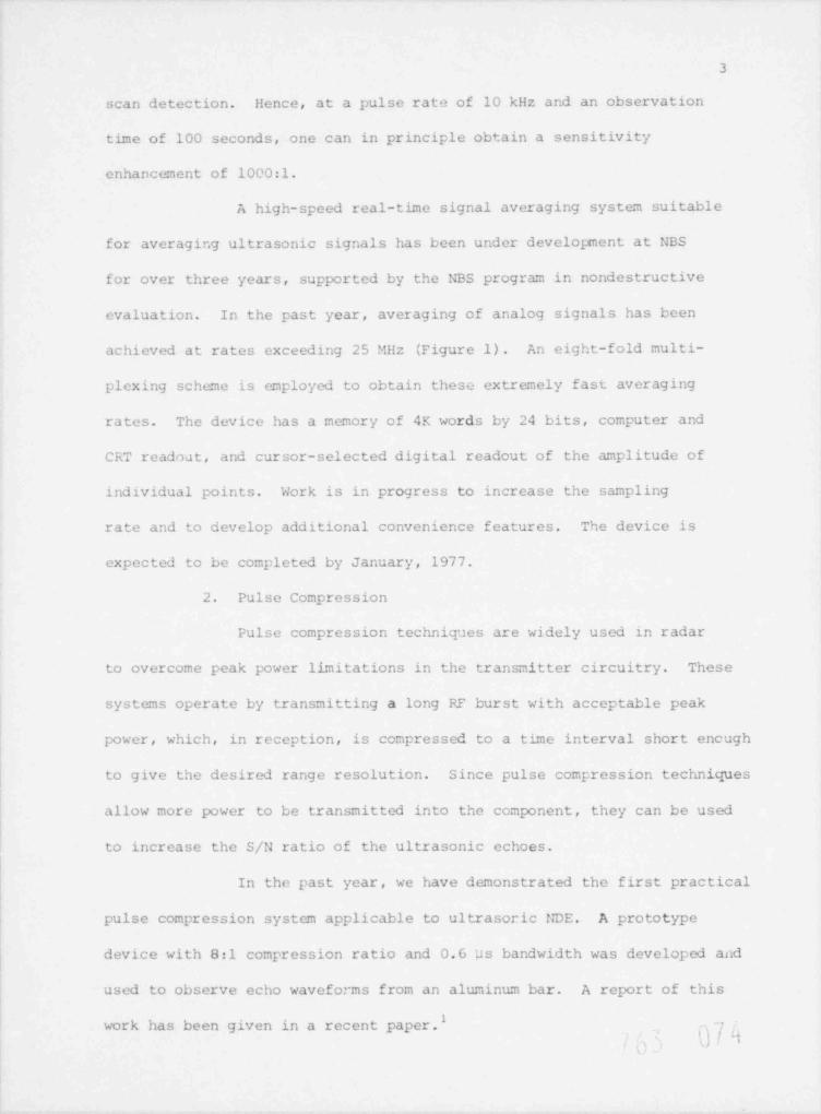
scan detection. Hence, at a pulse rate of 10 kHz and an observation
tbme of 100 seconds, one can in principle obtain a sensitivity
enhancement of 1000:1.
A high-speed real-time signal averaging system suitable
for averaging ultrasonic signals has been under development at NBS
for over three years, supported by the NBS program in nondestructive
evaluation. In the past year, averaging of analog signals has been
achieved at rates exceeding 25 MHz (Figure 1). An eight-fold multi-
plexing scheme is employed to obtain these extremely fast averaging
rates. The device has a memory of 4K words by 24 bits, computer and
CRT readodt, and cursor-selected digital readout of the amplitude of
individual points. Work is in progress to increase the sampling
rate and to develop additional convenience features. The device is
expected to be completed by January, 1977.
2. Pulse Compression
Pulse compression techniques are widely used in radar
to overcome peak power limitations in the transmitter circuitry. These
systems operate by transmitting a long RF burst with acceptable peak
power, which, in reception, is compressed to a tbme interval short encugh
to give the desired range resolution. Since pulse compression techniques
allow more power to be transmitted into the component, they can be used
to increase the S/N ratio of the ultrasonic echoes.
In the past year, we have demonstrated the first practical
pulse compression system applicable to ultrasoric NDE. A prototype
device with 8:1 compression ratio and 0.6 us bandwidth was developed and
used to observe echo waveforms from an aluminum bar. A report of this
work has been given in a recent paper.1O I ,t
,
<

4
2.1 Basic Principles of Pulse Compression
The most common waveform employed in pulse compression
systems is the linear F.M. or " chirp" waveform. The ideal chirp pulse,
shown schematically in Figure 2a, is an RF burst of constant envelope
amplitude, with frequency varying between f and f in time T. This1 2
waveform may be compressed to that shown in Figure 2b by passing it
through a dispersive delay line whose slope of frequency vs. time delay
is equal and of opposite sign to that of the F.M. waveform. In practical
systems, the compressed signal has a halfwidth of 1/|f -f2|E 1/B, where1
B is the bandwidth of the dispersive filter. The original F.M. waveform
has thus been compressed by a factor equal to BT.
A dispersive delay line, based on a surface acoustic wave
interdigital transducer, is schematically illustrated in Figure 2c. The
various frequency components of the F.M. waveform are launched on the
piezoelectric substrate only by electrodes whose spacing is about one-
half wavelength. The low frequency components thus travel a longer
distance and undergo a longer delay than the high frequency components
before reaching the broadband output element. Since the low frequency
Iortion of the waveform is inserted first into the device, all the
components appear simultaneously at the output to give a compressed
pulse.
One of the undesirable results of this compression process
is the appearance of time sidelobes on both sides of the compressed
pulse. Since the F.M. burst has a rectangular envelope, the output
waveform will resemble a (sin t)/t function, with first sidelobes only
13 dB down from the main lobe. These sidelobes may be reduced by suitable
amplitude and phase weighting (apodization) at the expense of main lobe,, _
|9 0!'
5
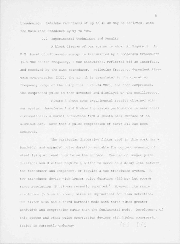
broadening. Sidelobe reductions of up to 40 dB may be achieved, with
the main lobe broadened by up to 50%.
2.2 Experimental Techniques and Results
A block diagram of our system is shown in Figure 3. An
F.M. burst of ultrasonic energy is transmitted by a broadband transducer
(5.5 MHz center frequency, 5 MHz bandwidth) , reflected off an interface,
and received by the same transducer. Following frequency dependent tbme-
gain compensation (TGC), the s i< il is translated to the operating
frequency range of the chirp filt (30-34 MHz), and then compressed.
The compressed pulse is then detected and displayed on the oscilloscope.
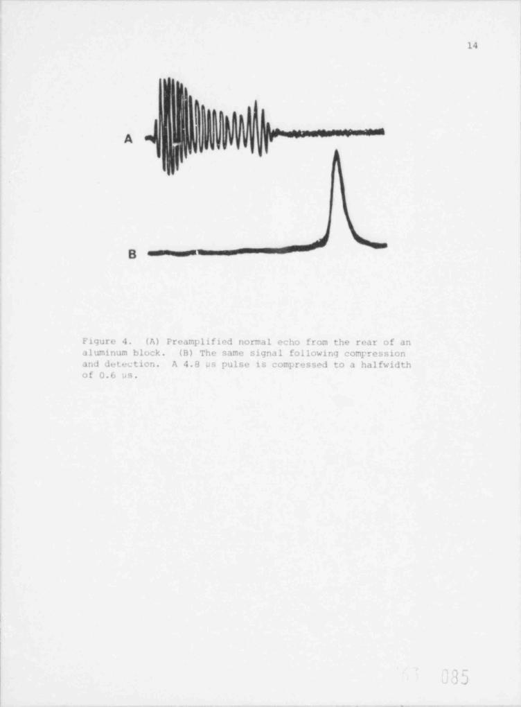
Figure 4 shows some experimental results obtained with
our system. Waveforms A and B show the system performance in near ideal
circumstances, a normal reflection from a smooth back surface of an
aluminum bar. Note that a pulse compression of about 8:1 has been
achieved.
The particular dispersive filter used in this work has a
bandwidth and expanded pulse duration suitable for contact scanning of-
steel lying at least 3 cm below the surface. The use of longer pulse
durations would either require a buffer to serve as a delay line between
the transducer and component, or require a two transducer system. A
two transducer device with longer pulse duration (420 ps) but poorer
recently reported.2 However, its rangerange resolution (8 ps) was
resolution (1 5 cm in steel) makes it impractical for flaw detection.
Our filter also has a third harmonic mode with three times greater
bandwidth and compression ratio than the f undamental mode. Development of
this system and other pulse compression devices with higher compression^' p7
ratios is currently underway. tj/ v

6
3. Other High-Sensitivity Techniques
We are planning to construct a high power insonification
system in FY 77. The maximum power which will be employed will be
dictated by the power handling capacity of the transducer elements.
Another area to be explored is power concentration in the material by
the use of an electronically-focused concentric annular array. This
approach would also have the additional advantage of improving lateral
resolution. Finally, sensitivity enhancement by use of acoustic
matching elements between the transducer and material will be investigated.
Insertion losses as low as 6 dB have been reported for impedance
matching by means of 1/4 wave plates. Impedance matching also results
in broadening the frequency response of the transducer, thus yielding
increased spatial resolution and increased range for spectral analysis.
4. Electromagnetic Transducers
Electromagnetic transducers have many characteristics
which make them desirable for nuclear reactor monitoring. Because
they are contactless, electromagnetic transducers lend themselves to
automated and reproducible scanning and are suitable for monitoring
componen t s in motion cr at high temperatures. Their principal probl'me
is lack of sensitivity (insertion loss of % 60 dB relative to PZT).
This drawback can be su rmoun ted , however, by the use of our signal
averaging / pulse compression system, since it would provide a sensi-
tivity enhancement of 60 dB in several seconds of averaging. Another
major problem has been the large size and weight of the magnets used
to generate the high magnetic fields necessary for high sensitivity.
Accordingly, we have developed compact and lightweight electromagnetic
() / /'
,

7
transducers incorporating very high field cobalt-samarium magnets.
3This work is fully described in a paper recently published and in
another paper now in press."
B. Techniques for Background Discrimination and Measurnmentof Bulk '4aterial Properties
1. Multifrequency Tranceiver System
In a recent paper in the Soviet Journal of Nondestructive
Testing 5, considerable success was reported in discriminating against
background by simultaneously transmitting and detecting at two or three ultra-
sonic frequencies. Scattering by dendritic structures within welds was
found to constructively or destructively interfere, depending on the insonify-
ing frequency, thereby leading to pronounced amplitude changes with frequency.
Scattering from flaws, on the other hand , exhibited a smooth and gradual
change of intensity with frequency and could thus be distinguished from
microstructural scattering.
Because of the success of this work, it was decided to
construct a multiple-frequency tranceiver system. An output at two
arbitrary frequencies is generated by a digital double-sideband
suppressed-carrier technique. Capability for generating two or more
harmonically-related signals is also provided. After wideband
amplification, the received signal is heterodyned to an IF f requency
region and then sent to different filter / detectors to yield frequency-
resolved information.
The system is now capable of yielding the amplitude ratio
at two frequencies. A circuit for measuring the relative phase of two
harmonically-related frequencies is under development. A paper describing
this system will be submitted for publication in 1977.
,
_,
(
8
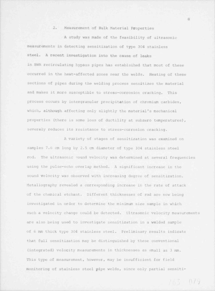
2. Measurement of Bulk tiaterial Properties
A study was made of the feasibility of ultrasonic
measurements in detecting sensitization of type 304 stainless
steel. A recent investigation into the cause of leaks
in BWR recirculating bypass pipes has establsihed that most of these
occurred in the heat-affected zones near the welds. Heating of these
sections of pipes during the welding process sensitizes the material
and makes it more susceptible to stress-corrosion cracking. This
process occurs by intergranular precipitation of chromium carbides,
which, although affecting only slightly the material's mechanical
properties (there is some loss of ductility at subzero temperatures),
severely reduces its resistance to stress-corrosion cracking.
A variety of stages of sensitization was examined on
samples 7.6 cm long by 2.5 cm diameter of type 304 stainless steel
rod. The ultrasonic "ound velocity was determined at several frequencies
using the pulse-echo overlap method. A significant increase in the
sound velocity was observed with increasing degree of sensitization.
:tetallography revealed a corresponding increase in the rate of attack
of the chemical etchant. Different thicknesses of rod are now being
investigated in order to determine the minimum size sample in which
such a velocity change could be detected. Ultrasonic velocity measurements
are also being used to investigate sensitization in a welded sample
of 6 mm thick type 304 stainless steel. Preliminary results indicate
that full sensitization may be distinguished by these conventional
(integratcd) velocit*/ measurements in thicknesses as small as 3 mm.
This type of measurement, however, may be insufficient for field
monitoring of stainless steel pipe welds, since only partial sensiti-
i'/ /

9
Zation can occur and the sensitization of interest is confined to the
inside surface. A more sensitive ultrasonic velocity mea sur e:nent , based
on computerized ultrasonic tomography, should be capable of detecting
such small perturbations. An experi:nental and theoretical study of
the potential of this technique for I;DE of materials has recently been
published.6
s
s () y

10
IV SUMMARY
Significant progress has been achieved in the past year in
developing high sensitivity techniques for ultrasonic inspection
of nuclear reactor components. Worx has been carried out on high-
frequency signal averaging, pulse compression, compact electro-
magnetic transducers, computer-assisted tomography, and detection of
sensitization vi stainless steel by ultrasonic velocity measurements.
Papers have been published on pulse compression, electromagnetic
transducers, and computer-assisted tomography, and additional papers
are expected to be submitted in 1977 on signal averaging, multi-
frequency transception, and the sensitization problem. Efforts in
FY 77 will concentrate on the development of techniques for dis-
crbnination against random noise and on their application to nuclear
reactor moni'oring.
0, D0t

11
V. REFERENCES
1. S. I. Parks and M. Linzer, Proc. SPIE (In Press)
2. F. Lam and J. Szilard, Ultrasonics, 14,, 111 (1976).
3. B. W. Maxfield, M. Linzer, W. B. McConnaughey and J. I; Hulbert,
Proc. IEEE Ultrasonics Symposium (1976).
4. B. W. Maxfield, IEEE Trans., Sonics and Ultrasonics (In Press) .
5. Soviet J. Mondestructive Testing (cover-to-cover translationof Defektoskopiya) 81-88 (1974).
6. A. C. Kak and C. V. Jakowatz, Jr., and M. Linzer, Proc.
Second Conference Automated Inspection and Product Control,235, IIT Press, (1976),
- FGO ij O L

A U
.. s . ,
_y,
7 ;_ --. . .
,-
. _- [, . . , . .- *
.-.
':- s.
.. . - - t, . .. ~... . - s . .- .- . ,
,.,
#- - '
*
.. h .a.m '.J
..,
< . '_ g.,- - -
-
'-
_ . , - ,, 4 , .,. ;.,/ - - . ,
- . ~ , _-,. , . . .
, ,. ..
, ,
..- -
, k. y, - : - '
,,
... _ _
''.'
. . . ... . .
. ,y y-_
. ., 3 , .,.
~ . _ ,.*
,
.g - as ' . . .. ,. - .
.; :- .- - - .. - ' y'
-,
., .,.
J 4 .,
,
-,.
. e * . . . 4 e'
. .*
.c .- .;
..*
- : '; . .- . , - {, ' ,.' e4 _. ..
.
-. .
-.
- e '',
. . ,,4., . .. .' - 1- r '. y* . ., . .g.?y . . ,.
.
. 7-. g..... . .. . .
-
Q -' ' '
f. ' .. s.. , .. _ . . .. ; . -
-- _ ,' ~
'. . * '. . L; :,. .
,
.:.. ..v>.. .o -(. J
.. .
. : ' 2--- .*. - -.p.g . '. . t c
- *
.
s .m . . . .
: .'e3 .
': .
.- , . .. . .r x . . , . ...
- ...
,
, . , ' . ' 1 .''
4' _.
. p . '. . .s, .
. , , , . . . . .. .. . ;.
'. . . , -.- -
, . ,.
* +'s,. . .,.w,.'
.
. ...
'
'
;,
i. - . .- . ' , . ' ,
. , , , .-
, .
.
~~ ,.. . ; . . -
.i j'
'- !] [,.. h ~. . . . . . . . .' * ' ; }. ...5'
. -
6;. .,7 . , ' . - . ''s., .-8
de .:: ..' . .#.
, ' ' . - -.
. ', . . .. ,? . . ..'
. . . .. C. - -
1...... ' . -. 3 a... - -
m....'. . 3. _ t c. . . . . - . #- . . . . ,S een .*p Figure 1. Demonstration of averaging capa-a bility ot NBS system. Input. sinusoid is
quantized by 16-level analog-to-digitalconverter and averaged 256 times. Horizontalaxis consists of 4,000 samples at 40 ns/ sample.A) Siinal without additive noise. B) Signalafter coise equal to one-sixteenth of fullscale is idded. Averaging smoothes out thecoarse quantization steps produced by theanalog-to-di tal converter.
"ar{t..
\_

13
(.1) INPUT SIGN AL (B) COMPRESSED PULSE
t i
\| i
gl t i' i
i i t
! I i 4 PATH OF W AVES' '
j ___p
+ __
'r
BR A BAND ELWENT:C) DiSPERSivE ELEMENy
C 2 PIEZOELECTRIC SUBSTRATE;
I| | |,~c ~
' DEPOSITED CONOUCTORS
Figure 2. Simplified picture of the dispersive filter usedto recompress " chirp"-encoded ultrasonic echoes. The fiiNrhas a delay v.!. f requency characteristic complementary tothe input chirp rate, so that low-frequency wavefronts " catchup" to high-frequency wavefronts to make a short compositepulse.
| p af ot;ENCY h -
* EPT T R A% WIT T E P
T k 4%5DUC.E qRE 8' E C TrVE
0%JE C T
TtWE GALNAMettFw ATM>%
i f*E QUE NC Y## ^
DE V E C TOR h a c ppf 't.TE R CO%VE RSION
Figure 3. Blcck diagram of pulse compression ultrasoundsystem.
~/ f s fi Q [1.i :o
14
|J.I
t
~ ''
\; j j'
,.
,
B ======== --
--
d nomal echo from the rear of anl tim u. bl , " I f 11 Win 9 C mrression
and detection. A 4"a WS PU is c mpressed to a halfwidtho f 0. 6 u s .
^ q ,-;
. ] .) J

UNITED ST ATES INUCLE AR REGULATORY COMMISSION
W ASHINGTON. D. C. 20555POST AGE AND FEES P AID 4
^''D 5'a''5 N. 'taa-
OFFicf AL BUSINESS "'' ' ' ' ~ ' ' ' ' '-"5' *PEN ALTY FOR PRIV ATE USE, 5 300 L J
i - : ti,v,o