development of ground-based search-coil magnetometer for
TRANSCRIPT

Journal of Magnetics 21(4), 509-515 (2016) https://doi.org/10.4283/JMAG.2016.21.4.509
© 2016 Journal of Magnetics
Development of Ground-Based Search-Coil Magnetometer for
Near-Earth Space Research
Jehyuck Shin1, Khan-Hyuk Kim1,2, Ho Jin1,2*, Hyomin Kim3, Jong-Woo Kwon1, Seungah Lee2,
Jung-Kyu Lee1, Seongwhan Lee1, Geonhwa Jee4, and Marc R. Lessard5
1School of Space Research, Kyung Hee University, Yongin 17104, Korea2Department of Astronomy and Space Science, Kyung Hee University, Yongin 17104, Korea
3Center for Solar-Terrestrial Research, New Jersey Institute of Technology, Newark 07102, USA4Korea Polar Research Institute, Incheon 21990, Korea
5Space Science Center, University of New Hampshire, Durham 03824, USA
(Received 21 October 2016, Received in final form 19 December 2016, Accepted 19 December 2016)
We report on development of a ground-based bi-axial Search-Coil Magnetometer (SCM) designed to measure
time-varying magnetic fields associated with magnetosphere-ionosphere coupling processes. The instrument
provides two-axis magnetic field wave vector data in the Ultra Low Frequency or ULF (1 mHz to 5 Hz) range.
ULF waves are well known to play an important role in energy transport and loss in geospace. The SCM will
primarily be used to observe generation and propagation of the subclass of ULF waves. The analog signals
produced by the search-coil magnetic sensors are amplified and filtered over a specified frequency range via
electronics. Data acquisition system digitizes data at 10 samples/s rate with 16-bit resolution. Test results show
that the resolution of the magnetometer reaches 0.1 pT/ at 1 Hz, and demonstrate its satisfactory
performance, detecting geomagnetic pulsations. This instrument is scheduled to be installed at the Korean
Antarctic station, Jang Bogo, in the austral summer 2016-2017.
Keywords : magnetometer, search-coil magnetometer, magnetosphere, ionosphere, ULF waves
1. Introduction
Magnetometers are one of the widely used instruments
for space research. Among various types of magnetometers,
“fluxgate” type magnetometers are often used to measure
DC magnetic fields while “search-coil (or induction)”
type magnetometers (SCM hereinafter) AC fields (dB/dt).
SCMs are typically bigger and heavier than the fluxgate
types. In spite of the disadvantage of their size, SCMs are
still indispensable because of their sensitivity and durability
[1]. A crucial parameter of SCMs is sensitivity to mea-
sure the weak signal in the Earth’s magnetic field [12].
SCMs have no upper limit of sensitivity range and
especially they are better than fluxgate magnetometers
above 1 Hz [1, 6]. The ground-based models of SCMs are
in operation in various locations for space research.
Example projects and institutes include Canadian Array
for Realtime Investigations of Magnetic Activity
(CARISMA), British Antarctic Survey (BAS), Augsburg
College and University of New Hampshire (UNH). This
paper describes a ground-based SCM developed by
Kyung Hee University (KHU) in collaboration with
UNH. The design is largely based on that of UNH whose
systems are widely used in the Arctic and Antarctic
regions. It will be installed at one of the Korean Antarctic
stations for the study of ULF wave generation and
propagation, which is the first development of such an
instrument by a Korean institute for near-earth space
research.
ULF waves play an important role in energy transfer
between the magnetosphere and ionosphere, and provide
key information about physical processes of the geospace
environment [10]. They cover roughly 1 mHz-5 Hz fre-
quency range: the subclass of the ULF wave include Pc1-
5 and Pi1-2 (see [5] for the subclass of ULF waves).
Various wave types of the ULF band have different occurr-
ence factors and plasma conditions. The magnetometer
described in this paper is designed to measure Pc1-2
Hz
©The Korean Magnetics Society. All rights reserved.
*Corresponding author: Tel: +82-31-201-3865
Fax: +82-31-201-3852, e-mail: [email protected]
ISSN (Print) 1226-1750ISSN (Online) 2233-6656
− 510 − Development of Ground-Based Search-Coil Magnetometer for Near-Earth Space Research − Jehyuck Shin et al.
waves and Pi1-2 waves which are typically associated
with electromagnetic ion cyclotron (EMIC) waves [7] and
substorm activities [4, 13], respectively. ULF waves trans-
mitted from the terrestrial magnetosphere are typically
observed at high-latitudes [11, 3]. In the austral summer
2016-2017, the SCM is scheduled to be installed at Jang
Bogo, the new Korean research station in Antarctica run
by Korea Polar Research Institute (KOPRI).
Section 2 describes the instrument design and system
configuration and specification of the SCM. Performance
test and field test results are shown in Section 3. In
section 4, we summarize the overall system development
and installation planning at the station.
2. System Design
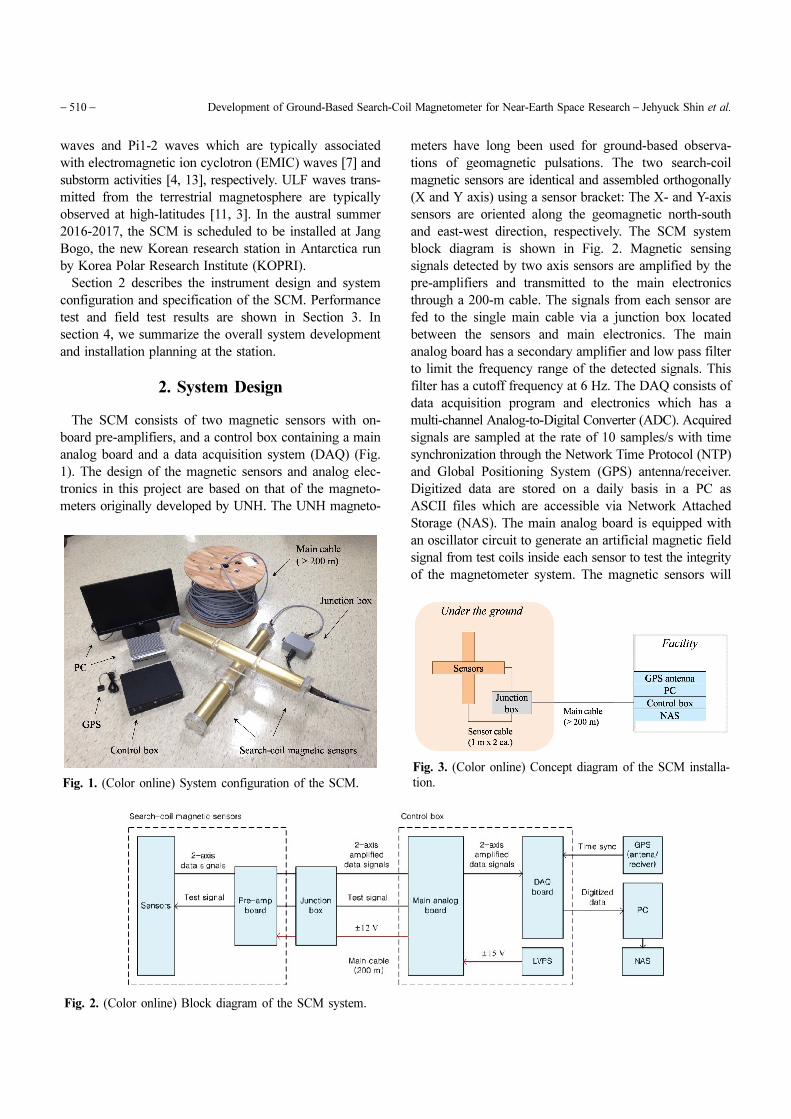
The SCM consists of two magnetic sensors with on-
board pre-amplifiers, and a control box containing a main
analog board and a data acquisition system (DAQ) (Fig.
1). The design of the magnetic sensors and analog elec-
tronics in this project are based on that of the magneto-
meters originally developed by UNH. The UNH magneto-
meters have long been used for ground-based observa-
tions of geomagnetic pulsations. The two search-coil
magnetic sensors are identical and assembled orthogonally
(X and Y axis) using a sensor bracket: The X- and Y-axis
sensors are oriented along the geomagnetic north-south
and east-west direction, respectively. The SCM system
block diagram is shown in Fig. 2. Magnetic sensing
signals detected by two axis sensors are amplified by the
pre-amplifiers and transmitted to the main electronics
through a 200-m cable. The signals from each sensor are
fed to the single main cable via a junction box located
between the sensors and main electronics. The main
analog board has a secondary amplifier and low pass filter
to limit the frequency range of the detected signals. This
filter has a cutoff frequency at 6 Hz. The DAQ consists of
data acquisition program and electronics which has a
multi-channel Analog-to-Digital Converter (ADC). Acquired
signals are sampled at the rate of 10 samples/s with time
synchronization through the Network Time Protocol (NTP)
and Global Positioning System (GPS) antenna/receiver.
Digitized data are stored on a daily basis in a PC as
ASCII files which are accessible via Network Attached
Storage (NAS). The main analog board is equipped with
an oscillator circuit to generate an artificial magnetic field
signal from test coils inside each sensor to test the integrity
of the magnetometer system. The magnetic sensors will
Fig. 1. (Color online) System configuration of the SCM.
Fig. 2. (Color online) Block diagram of the SCM system.
Fig. 3. (Color online) Concept diagram of the SCM installa-
tion.

Journal of Magnetics, Vol. 21, No. 4, December 2016 − 511 −
be installed under the ground or snow approximately 200
m away from the facility where the main electronics will
be installed to minimize electromagnetic interferences
(Fig. 3).
The sensor housing is designed to be durable for
outdoor use (e.g., physical strength and waterproofness).
The control box and computer will be located inside the
station facility.
2.1. Sensor
The search-coil magnetic sensors are generally com-
posed of enamel-coated copper wires wound around a
high permeability (µ) ferromagnetic core to draw high
voltage across a magnetic sensor coil [8, 9]. To achieve
appropriate amplification for our applications, hundreds
of thousands coil turns are implemented on a core. Our
coil spools are made of Acetal (Delrin®) which has no
static discharge and high strength. Each spool has tens of
thousands coil turns and dozens of spools were assembled
to make up a single coil. The spools, core and pre-am-
plifier are housed in a polycarbonate tube (Fig. 4). Each
sensor is 920 (L) × 130 (D) mm in size and 10.5 kg in
mass. The sensor housing is designed to be waterproof for
outdoor use as described earlier and composed of easily
disassemblable parts for easy repair (Fig. 5). The sensors
also have a few tens of turns of wire to serve as a test coil
also as described earlier.
The main purpose of the pre-amplifiers is to amplify
signals before transmitting them to the main analog
circuit via the long (200 m) main cable. The resonance
frequency of the pre-amplifier combined with the coil is 4
Hz. The power for the pre-amplifier (± 12 V) is supplied
from the main analog board via the main cable (Fig. 5,
right).
2.2. Main Analog Board
The main analog board amplifies signals from the pre-
amplifiers. There are three gain levels which will be ad-
justed to obtain magnetic field wave events of interest on
a desired level. The resonance frequency is set approxi-
mately at 4 Hz (defined as −3 dB from the maximum
amplitude). The board also contains a circuit that gene-
rates an oscillating signal (1 Hz, Vpk-pk) to generate a
known magnetic field inside the magnetic sensor to test
the integrity of the magnetometer system.
Power regulators are implemented to supply ± 12 V to
the pre-amplifiers and main analog board, converting ± 15
V from the linear power supply. The main analog board is
150 × 130 mm in size, 88 g in mass and it is placed in the
control box.
2.3. Data Acquisition System
Digitization and processing of data signals transmitted
from the main analog board are performed in the DAQ.
Our system employs the LabJack U6 model to serve as a
multi-channel ADC which handles bi-axial data from the
X and Y-axis sensors. The DAQ board is powered by the
USB port of an industrial computer. The DAQ is run by a
program based on LabVIEW. The user interface is shown
in Fig. 6. The sampling rate is 10 samples/s/axis, yield-
ing 30.4 Mbyte/day for bi-axial data. A NTP and GPS
antenna/receiver are used for accurate time synchroni-
zation with 1 ms time accuracy. Acquired data are saved
automatically on the computer and transferred to a NAS
in real time for public access.
2.4. System Specification
The specification of the SCM is shown in Table 1
which summarizes the technical details. The following
section describes the tests performed.Fig. 4. (Color online) Search-coil magnetic sensor of the
SCM.
Fig. 5. (Color online) Spool and an on-board amplifier configuration. Each part has a slide fit design (left, middle). The pre-amp
board is installed at the end of sensor configuration (right).
− 512 − Development of Ground-Based Search-Coil Magnetometer for Near-Earth Space Research − Jehyuck Shin et al.
3. Performance Tests
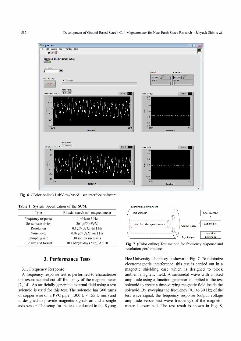
3.1. Frequency Response
A frequency response test is performed to characterize
the resonance and cut-off frequency of the magnetometer
[2, 14]. An artificially generated external field using a test
solenoid is used for this test. The solenoid has 360 turns
of copper wire on a PVC pipe (1300 L × 155 D mm) and
is designed to provide magnetic signals around a single
axis sensor. The setup for the test conducted in the Kyung
Hee University laboratory is shown in Fig. 7. To minimize
electromagnetic interference, this test is carried out in a
magnetic shielding case which is designed to block
ambient magnetic field. A sinusoidal wave with a fixed
amplitude using a function generator is applied to the test
solenoid to create a time-varying magnetic field inside the
solenoid. By sweeping the frequency (0.1 to 30 Hz) of the
test wave signal, the frequency response (output voltage
amplitude versus test wave frequency) of the magneto-
meter is examined. The test result is shown in Fig. 8,
Fig. 6. (Color online) LabView-based user interface software.
Table 1. System Specification of the SCM.
Type Bi-axial search-coil magnetometer
Frequency response 1 mHz to 5 Hz
Sensor sensitivity 364 µV/(nT·Hz)
Resolution 0.1 pT/ @ 1 Hz
Noise level 0.07 pT/ @ 1 Hz
Sampling rate 10 samples/sec/axis
File size and format 30.4 Mbyte/day (2 ch), ASCII
Hz
Hz
Fig. 7. (Color online) Test method for frequency response and
resolution performance.

Journal of Magnetics, Vol. 21, No. 4, December 2016 − 513 −
showing the magnetometer’s resonance frequency peaks
at ~4 Hz and its cutoff frequency at ~6 Hz (defined as −3
dB corner frequency).
3.2. Resolution
A resolution of magnetometer, a measure of the smallest
change it can detect, is one of the very important features
defining the sensor performance. The noise level of the
system also needs to be characterized to specify its re-
solution. This section describes how the sensor resolution
and noise level are measured. This test is similar to the
frequency test described in the previous section except
that the input test signal amplitude is varied at a fixed
frequency until the applied signal is only above 3 dB
above the noise floor in a spectral domain (this is called
“minimum discernible signal or MDS). This is measured
by observing an output spectral peak using a spectrum
analyzer [2]. Also this test is conducted in a magnetic
shielding case and thus the noise generated internally by
the magnetometer can be verified. Selected screenshots of
the spectrum analyzer measurements at 0.5 Hz and 1 Hz
are shown in Figure 9. To specify the resolution, an MDS
is represented by equation as follows;
(1)
where µ0 is the permeability of a sensor core, n is turns of
test solenoid per unit length and I is an input current on a
test solenoid. The resolution and noise level at selected
frequencies are presented in Table 2.
B = µ0nI = µ0nV
R---
Fig. 8. (Color online) Frequency response curve. The resonance peak is shown near ~4 Hz.
Fig. 9. (Color online) Screenshots of spectrum analyzer show exact responses of the search-coil magnetometer at 0.5 Hz (left) and
1 Hz (right) which is supplied by test solenoid frequency. Red arrows indicate spectral peak at the test frequency and it is ~3 dB
above the noise level.
− 514 − Development of Ground-Based Search-Coil Magnetometer for Near-Earth Space Research − Jehyuck Shin et al.
3.3. Field Test
The overall performance of the magnetometer has been
examined at a field site in preparation for installation at
the Jang Bogo Antarctic Station. The test site is currently
used for an Astronomical Observatory in Bohyun Mountain,
South Korea (BOAO, 36.1 N, 128.6 E, geographic) in
which electromagnetic disturbance due to power lines and
human activity is known to be minimal. A single axis
magnetic sensor is installed approximately 200 m away
from the observatory building and buried under the ground.
The sensor is oriented along the local geomagnetic north-
south direction. Both frequency responses over sweeping
frequencies and long-term (~38 hours) operation test have
been conducted. The frequency response test is done
using the external test solenoid as described in Section
3.1. Figure 10 shows the frequency response test in the
field, showing the resonance frequency and cut-off fre-
quency of the SCM at 5 Hz and 6 Hz, respectively, which
are based on the initial design of frequency range of the
SCM.
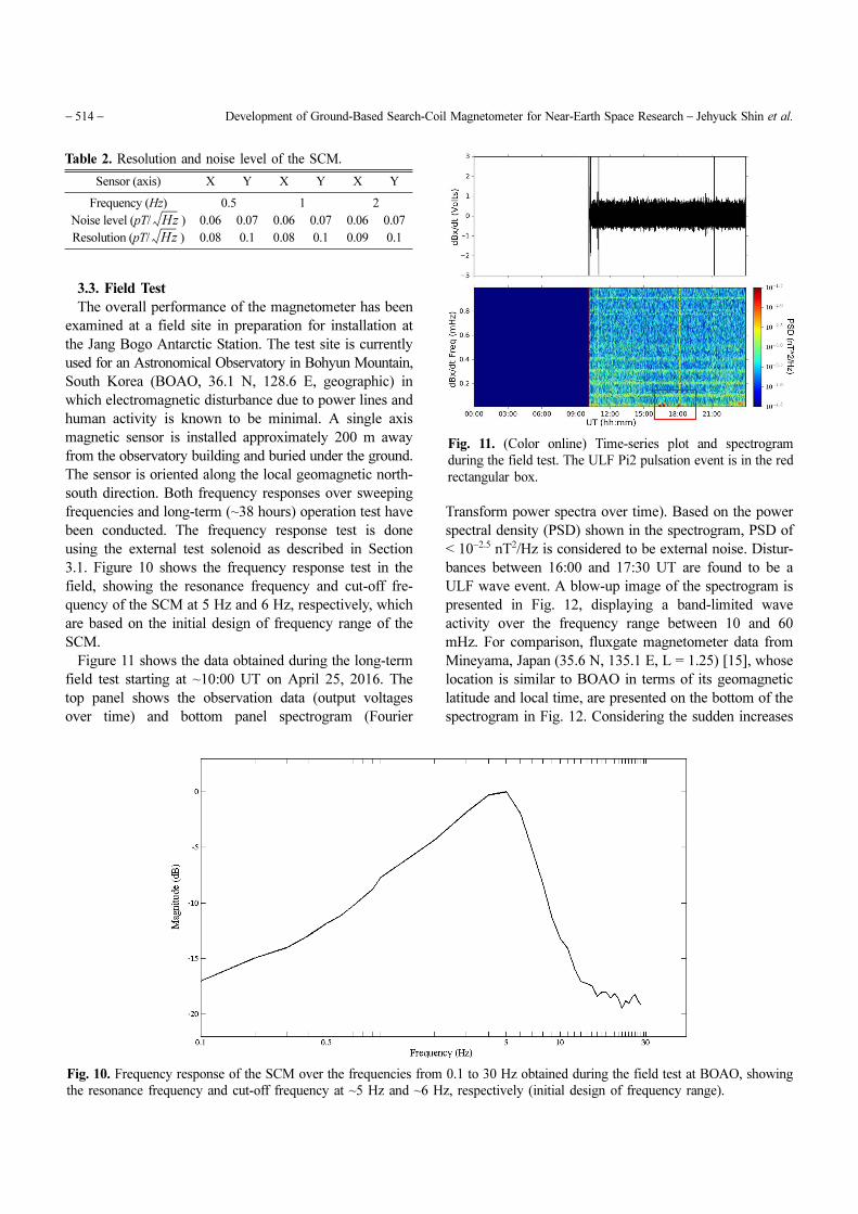
Figure 11 shows the data obtained during the long-term
field test starting at ~10:00 UT on April 25, 2016. The
top panel shows the observation data (output voltages
over time) and bottom panel spectrogram (Fourier
Transform power spectra over time). Based on the power
spectral density (PSD) shown in the spectrogram, PSD of
< 10−2.5 nT2/Hz is considered to be external noise. Distur-
bances between 16:00 and 17:30 UT are found to be a
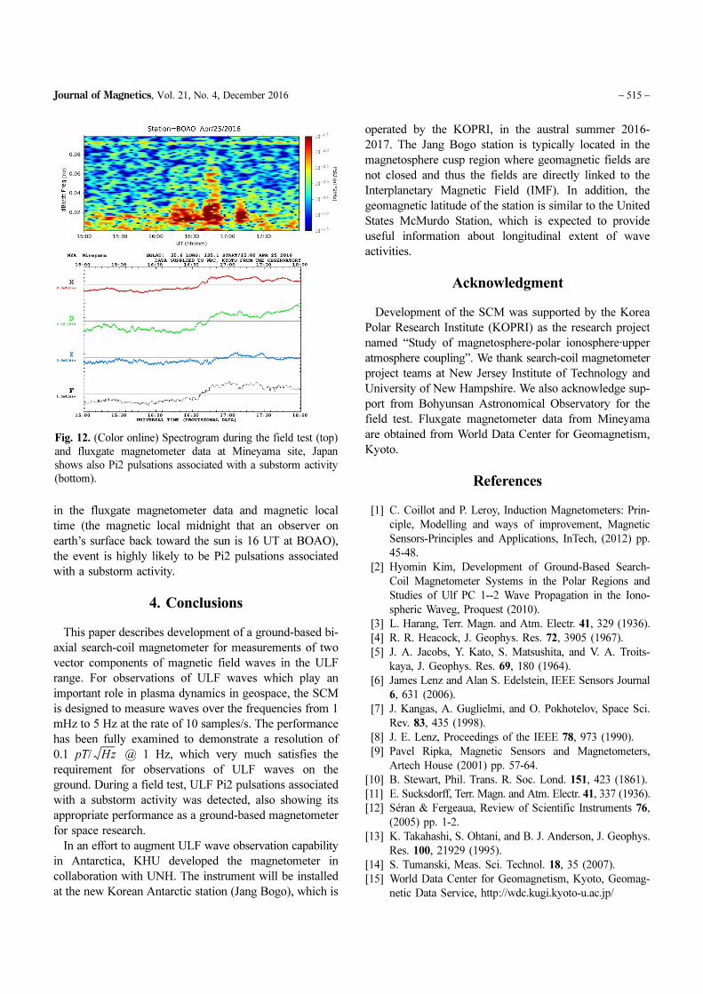
ULF wave event. A blow-up image of the spectrogram is
presented in Fig. 12, displaying a band-limited wave
activity over the frequency range between 10 and 60
mHz. For comparison, fluxgate magnetometer data from
Mineyama, Japan (35.6 N, 135.1 E, L = 1.25) [15], whose
location is similar to BOAO in terms of its geomagnetic
latitude and local time, are presented on the bottom of the
spectrogram in Fig. 12. Considering the sudden increases
Fig. 10. Frequency response of the SCM over the frequencies from 0.1 to 30 Hz obtained during the field test at BOAO, showing
the resonance frequency and cut-off frequency at ~5 Hz and ~6 Hz, respectively (initial design of frequency range).
Fig. 11. (Color online) Time-series plot and spectrogram
during the field test. The ULF Pi2 pulsation event is in the red
rectangular box.
Table 2. Resolution and noise level of the SCM.
Sensor (axis) X Y X Y X Y
Frequency (Hz) 0.5 1 2
Noise level (pT/ ) 0.06 0.07 0.06 0.07 0.06 0.07
Resolution (pT/ ) 0.08 0.1 0.08 0.1 0.09 0.1
Hz
Hz
Journal of Magnetics, Vol. 21, No. 4, December 2016 − 515 −
in the fluxgate magnetometer data and magnetic local
time (the magnetic local midnight that an observer on
earth’s surface back toward the sun is 16 UT at BOAO),
the event is highly likely to be Pi2 pulsations associated
with a substorm activity.
4. Conclusions
This paper describes development of a ground-based bi-
axial search-coil magnetometer for measurements of two
vector components of magnetic field waves in the ULF
range. For observations of ULF waves which play an
important role in plasma dynamics in geospace, the SCM
is designed to measure waves over the frequencies from 1
mHz to 5 Hz at the rate of 10 samples/s. The performance
has been fully examined to demonstrate a resolution of
0.1 pT/ @ 1 Hz, which very much satisfies the
requirement for observations of ULF waves on the
ground. During a field test, ULF Pi2 pulsations associated
with a substorm activity was detected, also showing its
appropriate performance as a ground-based magnetometer
for space research.
In an effort to augment ULF wave observation capability
in Antarctica, KHU developed the magnetometer in
collaboration with UNH. The instrument will be installed
at the new Korean Antarctic station (Jang Bogo), which is
operated by the KOPRI, in the austral summer 2016-
2017. The Jang Bogo station is typically located in the
magnetosphere cusp region where geomagnetic fields are
not closed and thus the fields are directly linked to the
Interplanetary Magnetic Field (IMF). In addition, the
geomagnetic latitude of the station is similar to the United
States McMurdo Station, which is expected to provide
useful information about longitudinal extent of wave
activities.
Acknowledgment
Development of the SCM was supported by the Korea
Polar Research Institute (KOPRI) as the research project
named “Study of magnetosphere-polar ionosphere·upper
atmosphere coupling”. We thank search-coil magnetometer
project teams at New Jersey Institute of Technology and
University of New Hampshire. We also acknowledge sup-
port from Bohyunsan Astronomical Observatory for the
field test. Fluxgate magnetometer data from Mineyama
are obtained from World Data Center for Geomagnetism,
Kyoto.
References
[1] C. Coillot and P. Leroy, Induction Magnetometers: Prin-
ciple, Modelling and ways of improvement, Magnetic
Sensors-Principles and Applications, InTech, (2012) pp.
45-48.
[2] Hyomin Kim, Development of Ground-Based Search-
Coil Magnetometer Systems in the Polar Regions and
Studies of Ulf PC 1--2 Wave Propagation in the Iono-
spheric Waveg, Proquest (2010).
[3] L. Harang, Terr. Magn. and Atm. Electr. 41, 329 (1936).
[4] R. R. Heacock, J. Geophys. Res. 72, 3905 (1967).
[5] J. A. Jacobs, Y. Kato, S. Matsushita, and V. A. Troits-
kaya, J. Geophys. Res. 69, 180 (1964).
[6] James Lenz and Alan S. Edelstein, IEEE Sensors Journal
6, 631 (2006).
[7] J. Kangas, A. Guglielmi, and O. Pokhotelov, Space Sci.
Rev. 83, 435 (1998).
[8] J. E. Lenz, Proceedings of the IEEE 78, 973 (1990).
[9] Pavel Ripka, Magnetic Sensors and Magnetometers,
Artech House (2001) pp. 57-64.
[10] B. Stewart, Phil. Trans. R. Soc. Lond. 151, 423 (1861).
[11] E. Sucksdorff, Terr. Magn. and Atm. Electr. 41, 337 (1936).
[12] Séran & Fergeaua, Review of Scientific Instruments 76,
(2005) pp. 1-2.
[13] K. Takahashi, S. Ohtani, and B. J. Anderson, J. Geophys.
Res. 100, 21929 (1995).
[14] S. Tumanski, Meas. Sci. Technol. 18, 35 (2007).
[15] World Data Center for Geomagnetism, Kyoto, Geomag-
netic Data Service, http://wdc.kugi.kyoto-u.ac.jp/
Hz
Fig. 12. (Color online) Spectrogram during the field test (top)
and fluxgate magnetometer data at Mineyama site, Japan
shows also Pi2 pulsations associated with a substorm activity
(bottom).