development of continuous crystallisation processes for...
TRANSCRIPT
Alastair J. Florence, CMAC, University of Strathclyde Drug Delivery and Formulation Forum, Berlin May 2016
Development of Continuous Crystallisation Processes for Consistent Crystal Products

Drivers for Change in Manufacturing
“Do we have the correct architecture for manufacturing in the industry? Now is the time to look at new infrastructure with smaller, more agile facilities for end to end manufacture.”
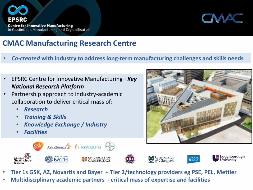
CMAC Manufacturing Research Centre • Co-created with industry to address long-term manufacturing challenges and skills needs
• EPSRC Centre for Innovative Manufacturing– Key National Research Platform
• Partnership approach to industry-academic collaboration to deliver critical mass of:
• Research • Training & Skills • Knowledge Exchange / Industry • Facilities
• Tier 1s GSK, AZ, Novartis and Bayer + Tier 2/technology providers eg PSE, PEL, Mettler • Multidisciplinary academic partners - critical mass of expertise and facilities

synthesis crystallisation isolation/drying secondary manufacture
• Improve particulate based product supply via continuous processes
• Develop understanding of complex interactions between process, materials and quality
• Develop flexible continuous process technologies and understanding to deliver:
Consistency Manufacturability Performance
Accelerate the adoption of continuous processing in pharmaceutical manufacturing
Demand Led Research Scope
Robustness

Production of Particles and Controlling Particle Attributes for Performance

Process parameters
Physical transformations
Process parameters
Physical transformations
Molecular attributes Particle attributes Bulk attributes
Problems with Pharmaceutical Particles
But molecules may adopt many possible solid forms = different size, shape, surfaces, microstructure
• Crystal structure prediction is developing • Complex transformation dynamics • Limited structure-property-process relationships • Measurement gaps at molecular length/time
scale • Surfaces poorly understood • Microstructure (e.g. defects) difficult to measure
What particle is required? How to make?

Poor Crystallisation Control
300µm Fines in crystallisation of
form of L-glutamic acid – e.g. variable filtration
times
Mixture of carbamazepine forms II and III due to in situ
transformation – variable dissolution rates
Supersaturation, secondary nucleation, attrition, agglomeration, encrustation and transformations can
impact on measurement, uniformity and quality
Uncontrolled growth on reactor walls (encrustation/ fouling) –
compromise heat transfer
Encrustation on UV probe– compromise measurement
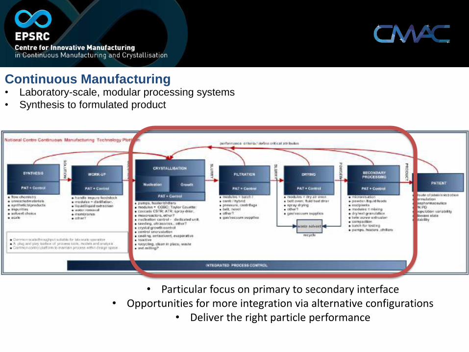
Continuous Manufacturing • Laboratory-scale, modular processing systems • Synthesis to formulated product
• Particular focus on primary to secondary interface • Opportunities for more integration via alternative configurations
• Deliver the right particle performance
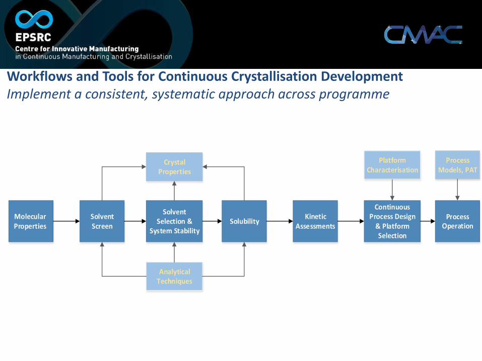
Workflows and Tools for Continuous Crystallisation Development Implement a consistent, systematic approach across programme

Stage 2: Solvent Screen
Parameter Design space
Transmission at (B.P. – 10) °C
> 95 %
Transmission at 20 °C
< 95 %
ICH Class 3 or 2
0
10
20
30
40
50
60
70
80
90
100Transmission at B.P. -10 °C. 100% = completely
dissolved Description • Assess solubility from library of
solvents • Broad range of solvent types and
functionality Methodology • 50 g/L of API mixed with solvent • Dissolution evaluated at 3
temperatures: • 20 °C • B.P. – 10 °C • Mid point
Selection Criteria for solvent screen
• 11 solvents out of 54 fall within design space and carried on to next stage
0
10
20
30
40
50
60
70
80
90
100Transmission at 20 °C. 100% = completely dissolved
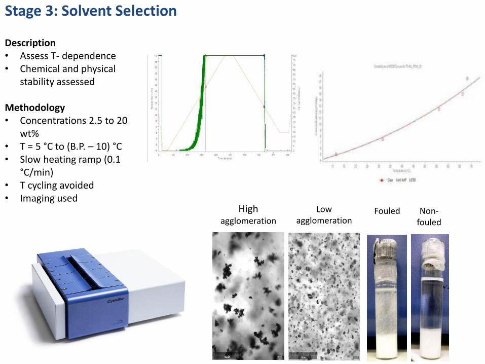
Stage 3: Solvent Selection
Description • Assess T- dependence • Chemical and physical
stability assessed
Methodology • Concentrations 2.5 to 20
wt% • T = 5 °C to (B.P. – 10) °C • Slow heating ramp (0.1
°C/min) • T cycling avoided • Imaging used
High agglomeration
Low agglomeration
Non-fouled
Fouled

Stage 3: Solvent Selection
Parameter Design space Chosen solvent
Upper temperature ≤ 90 °C 80 °C
Lower temperature ≥ 5 °C 5 °C
Yield ≥ 90 % 90 %
Solid fraction 10 to 25 % w/w 17 %
Metastable zone width > 5 °C 20 °C
Form and chemical stability at elevated temp.
> 24 hr > 24 hr
Agglomeration Low to none Low to none
Fouling None None
• Only 1 solvent out of 11 from previous stage met design space criteria: • 3-methyl-1-butanol (iso-amyl alcohol)

Stage 4. In-line monitoring of crystallisation e.g. spectroscopic approaches
• Solubility determination
• Temperature dependent calibration using PLS modelling
Robust approach for calibration of methods required (C, T, particles)

Stage 5: System understanding Description • ID process conditions for
desired performance. • ID limits • Inform platform
selection, mixing, etc. Methodology • Range of tests developed
to assess: • Metastable zone • Secondary
nucleation • Growth rate • Fouling • Agglomeration
x y
z
S = 1.75
S = 2.00
Fouling induction times
Metastable zone widths
Secondary nucleation: Seeded vs. unseeded
Growth rates. Bulk and single crystal
Agglomeration

Continuous Crystallisation – Various Tools e.g
Static mixer (Kenics)
Alvarez & Myerson (2010) Crystal Growth & Design 10, 2219-2228.
Wong, Cui, et al. (2013) Crystal Growth & Design 13, 2514-2521.
Continuous secondary nucleator and tubular crystalliser
Quon, Zhang, et al. (2012) Crystal Growth & Design 12, 3036-3044.
Stirred tank (MSMPR) cascade
Continuous oscillatory baffled crystalliser
Lawton, Steele, et al. (2009) Organic Process Research & Development 13, 1357-1363.
Segmented tubular flow reactor
Eder, Schrank, et al. (2012) Crystal Growth & Design 12, 4733-4738.

Parameter Chosen solvent
Metastable zone width
22 to 35 °C
Min. supersaturation for secondary nucleation
S = 1.7 to 2.2
Growth rate 1.5 to 3 µm/min
Agglomeration Low to none
Fouling induction time
S = 1.75: 278 min
S = 2.00: 107 min
Stage 5: System understanding Results
Couple system understanding and crystalliser characterisation to determine design space for operation
Achievable supersaturation limited by heat
transfer
Residence time governed by equipment volume and pump specification
1 stage 1L MSMPR
3 stage 15L MSMPR
COBC PFR
Primary nucleation
Growth
Secondary nucleation
Primary/secondary nucleation
indistinguishable

Stage 6: Process understanding
Description • Experimental DoE
coupled with PBE to establish design space
Methodology • Batch seeded cooling
experiments used as basis for parameter estimation
• Covering a range of seed mass, cooling rate and power input
Expt. Seed mass (g)
Cooling rate (°C/min)
Power input (W/kg)
1 0.95 0.50 0.023
2 4.73 0.50 0.023
3 0.95 0.17 0.023
4 0.95 0.50 0.053
5 4.73 0.50 0.053
6 2.84 0.35 0.053
0
2
4
6
8
10
0.1 10 1000V
olu
me
%
CE diameter (μm)
SeedProduct - expt.
1.0
1.2
1.4
1.6
1.8
2.0
0.02
0.04
0.06
0.08
0.10
0.12
0.14
0.16
0.18
0 1000 2000 3000 4000 5000 6000 7000 8000 9000 10000
Sup
ersa
tura
tio
n
Mas
s fr
ac.
Time (s)
Concentration Solubility Supersaturation

Stage 6: Process understanding • Parameter estimation - power law growth model
0.00
0.04
0.08
0.12
0.16
0.20
1 10 100 1000
Vol
ume
frac
.
Particle size (μm)
Expt. 8 - PSD comparison
SeedProduct - expt.Product - model

Description Using model and knowledge gained from the workflow, perform a series of crystallisations to demonstrate concept Size band 1 - Dv50 ~ 30 μm, 3.5 kg • Generated through the nucleation of
supersaturated solution in rotor-stator wet mill
• 10 L seed miniplant module with IKA MagicLab in recycle loop. Cooled following profile from Optimax experiment at constant supersaturation
Stage 7: Proof of concept
0
2
4
6
8
10
12
1 10 100 1000
Vo
lum
e %
Particle size (μm)
1 Litre scale
10 Litrescale A10 Litrescale B

0
10
20
30
40
50
60
70
80
90
0 50 100 150 200
Tem
per
atu
re (
°C)
Residence time (min)
Temperature profile
COBC profile(model)
Constant Sprofile
Size band 2 Dv50 ~70 μm, 3.5 kg • Continuous seeded
crystallisation in COBC module. • 6.1 % seed loading, 166 min
residence time, 1180 min operating time (excluding start-up)
Size band 3 Dv50 ~ 155 μm, 6.5 kg • Continuous seeded
crystallisation in COBC module. • 9.9 % seed loading, 166 min
residence time, 2127 operating time (excluding start-up)
Seed addition Stage 7: Proof of concept
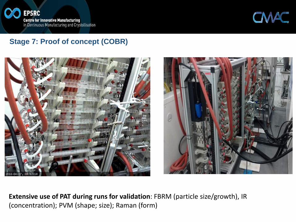
Stage 7: Proof of concept (COBR)
Extensive use of PAT during runs for validation: FBRM (particle size/growth), IR (concentration); PVM (shape; size); Raman (form)

Stage 7: Proof of concept (COBR)
Extensive use of PAT during runs for validation: FBRM (particle size/growth), IR (concentration); PVM (shape; size); Raman (form)

MSMPR campaign Dv50 ~ 80 μm, 2.5 kg • Continuous seeded
crystallisation in 3 stage MSMPR using 2 L vessels
• Stage temperatures: 63.8, 48.3 and 32.5 °C (maintain S < 1.35)
• 7.1 % seed loading, 172 min residence time, 980 operating time (excluding start-up)
Stage 7: Proof of concept
0.00
0.02
0.04
0.06
0.08
0.10
0.12
0.14
1 10 100 1000
Vo
lum
e fr
acti
on
Particle size (μm)
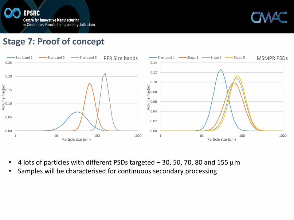
MSMPR PSDs Size band 1 Stage 1 Stage 2 Stage 3
0.00
0.05
0.10
0.15
0.20
0.25
1 10 100 1000
Vo
lum
e fr
acti
on
Particle size (μm)
PFR Size bands Szie band 1 Size band 2 Size band 3
Stage 7: Proof of concept
• 4 lots of particles with different PSDs targeted – 30, 50, 70, 80 and 155 mm • Samples will be characterised for continuous secondary processing

Continuous Filtration CRD GSK “Falcon” robotic platform and Bespoke rotary drum filter
‘Falcon’ - Accurately quantify filtration and washing perfomance Drum filter - scaled to take output from COBCs and isolate product stream with washing.
Acetanilide
Metacetamol
(Paracetamol API)
(Impurities)
(Ethanol / water)

Scale-up of co-crystallisation process from 0.3g (vial) → 30g (OBC)→ 1kg (COBC)
SEM
XRPD
Pawley fit to XRPD data from reclaimed sample of co-crystals (a, b, c (Å) = 26.44762, 5.31036, 34.27961; β (o) = 90.524, Rwp = 4.120)
vs. batch
• Phase pure co-crystal product • Consistent particle size
Zhao et al., CrystEngComm, 2014,16, 5769-5780

Getting The Right Form Manipulating properties through continuous spherical agglomeration
Particles (10s mm) Loose aggregates (100s mm) Intergrown, spherical agglomerates (100-1000 mm)
Dealing with poor powder flow
Transform ‘difficult’ particles into well behaved granules

Getting The Right Form Manipulating properties through continuous agglomeration
BL Droplet Formation
Crystal Wetting
Mixing Coalescence Consolidation
Material prep. Wetting and Nucleation Coalescence and Consolidation
CSTR Mixer
High shear
Microfluidic system
Key Process Parameters:- Time, Shear rate – PAT controlled Temperature
Multistage continuous processing to deliver modified attributes

Getting The Right Form Manipulating properties through continuous spherical agglomeration
• Granular API form of aspirin • 500 mm • Significantly improved flow properties • Suitable for direct compression

Flexible Process Streams (OSD)
Inputs ex Conti Cryst /
excipient
Formulation processes/
Transformation
Dose Form Tablets/Capsules/Pills/structured doses
Extrusion (melt/wet)
Compression, moulding, 3D
printing, capsule etc.
Wet granulation Batch/Cont/TS
Direct compression (batch/cont blend)
Roller Compaction

Exploiting Informatics • Exploiting ELN / networked instrument base to accumulate systematic data across different
systems • Complement mechanistic models with informatics-based tools
Applied also to solubility, nucleation, fouling, agglomeration, polymorphism, solvate formation

Acknowledgements
Academics • Professor Gavin Halbert • Dr Blair Johnston • Dr Alison Nordon • Dr Chris Price • Professor Chris Rielly • Dr John Robertson • Dr Jag Srai • Professor Jan Sefcik
Researchers • Bilal Ahmed • Maria Bruiglia • Michael Chrubrasik • Natalia Dabrowska • Andrew Dunn • Clarissa Forbes • Dimitris Fysikopoulos • Raaz Gurung • Fraser Mabbott • John McGinty • Francesca Perciballi • Hector Polyzois • Vishal Raval • Vaclav Svoboda • Stephanie Yerdelen
Post Docs • Dr Cameron Brown • Dr Tomas Harrington • Dr Anna Jawor-Bacynska • Dr Pól MacFhionnghaile • Dr Thomas McGlone • Dr Ebeneezer Ojo • Dr Elke Prasad • Dr Humera Siddique • Dr Vijay Srirambhatla • Dr Rene Steendam • Dr Anna Trybala ICT-CMAC • Dr Murray Robertson