development of aspheric surface polishing for x-ray mirrors · development of aspheric surface...
TRANSCRIPT

Development of Aspheric Surface Polishing for X-Ray Mirrors
Yoshimi Takeuchi, Anthony Beaucamp, Yoshiharu Namba
Richard Freeman (Zeeko Ltd.)
Fabricating super-smooth aspheric optics for future hard X-ray telescopes will
require a new process chain. An innovative two-step freeform finishing method
is presented, that combines fluid jet and precessed bonnet polishing on a common
7-axis CNC platform. The corrective capability of this finishing method is
demonstrated in the case of two different process chains for manufacturing
replication mandrels: Electroless Nickel mandrels used for DC magnetron
sputtering and Fused Silica mandrels used for thin glass slumping. A novel
bonnet tool-pathing method called “continuous precessing” is also presented,
which can deliver super-smooth anisotropic surface texture of 0.28 nm rms.
1.Introduction
X-ray radiations are created in space by extremely high energy celestial events. Such events
include supernova explosions, destruction of positrons, creation of black holes, as well as
the decay of radioactive matter in space. However, such high energy rays cannot be reflected
or refracted with conventional optics like other electro-magnetic radiations. Instead, the
total reflection of X-rays over flat and smooth surfaces at very shallow angle of incidence
was first reported by Compton in 1923. The discovery of this phenomenon called “grazing
incidence” reflection led to the suggestion by Wolter in 1952 of a number of optical
configurations using confocal paraboloid and hyperboloid sections to focus X-ray radiations.
The most practical, for the purpose of building of an X-ray space telescope, is known as the
Wolter type-1 configuration and shown in Fig. 1.
図 1 Wolter type-1 configuration for grazing incidence X-ray mirrors

When dealing with high energy radiations, there exists a relationship between form accuracy
and surface roughness of the optical surface on one hand, and the upper limit of radiation
energy that it can reflect (keV) and resolution of the images it can produce (arcs) on the
other hand. State-of-the-art finishing of molding dies has enabled the fabrication of X-ray
imaging telescopes by replication, such as ASCA, XMM-Newton, Suzaku and ASTRO-H shown in Fig.
2. But in future years, the goal of building high resolution aspheric hard X-ray telescopes
will require stringent specification: roughness less than 0.3 nm rms and deviation from
aspheric shape less than 50 nm P-V.
図 2 Past and future specifications of replicated X-ray telescopes.
Two possible process chains have been proposed in the literature to produce future thin
aspheric X-ray mirrors:
The first process relies on diamond turning of electroless nickel plated molding dies,
for thin aspheric mirror replication by DC magnetron sputtering (see Fig. 4).
The second process relies on freeform grinding to produce aspheric fused silica mandrels,
for replication of thin glass sheet by slumping process (see Fig. 5).
This paper focuses on the intermediate finishing steps that are necessary for realizing both
process chains. In particular, a novel concept is presented of combining fluid jet and
precessed bonnet polishing processes using a common 7-axis CNC platform, shown in Fig. 3.
図 3 7-axis CNC platform used for fluid jet and bonnet polishing.
ASCA XMM-Newton Suzaku ASTRO-H(10keV, 180arcs) (15keV, 20arcs) (12keV, 120arcs) (80keV, 100arcs) (100KeV, 20arcs)

This combination can correctively polish ultra-precise aspheric shapes on both electroless
nickel plated and fused silica mandrels. For final smoothing, the surfaces are then polished
with a novel precessed bonnet tool pathing method named “continuous precessing”. This new
method can deliver super-smooth anisotropic surface texture when used with nano-particles
slurry.
図 4 Process chain #1 for fabricating aspheric hard X
図 5 Process chain #2 for fabricating aspheric hard X
2.Corrective Polishing
2.1 Fluid Jet Polishing of Electroless Nickel
Fluid Jet Polishing (FJP) has been studied in recent years as a pot
for optical lenses and molds with a number of materials, such a glas
process, a mixture of water and abrasive particles is delivered by
nozzle of outlet diameter usually between 0.1 and 2.0 mm. The jet i
thus generating an influence spot which is moved across the surfac
programmed in to the 7-axis CNC machine.
Corrective polishing by fluid jet was demonstrated on a 100 mm diamete
measuring form on a Fizeau interferometer and feeding the error to a fee
Initial form error on the sample was 120 nm P-V (see Fig. 6). It was
P-V with the following polishing sequence:
(1) 4.0 µm Al2O3, 16 bar fluid pressure (45 nm P-V).
(2) 4.0 µm Al2O3, 8 bar fluid pressure (27 nm P-V).
(b) Fluid Jet (c) Continuous Precess(a) Diamond Turning
(b) Single Precess (c) Continuous Precess(a) Freeform Grinding
-ray shells
-
en
s
a
mp
e
r
d
(d) DC Magnetron Sputtering
Mandrel
ray shells
tial finish
and nickel.
pump to a
inges the w
to follow a
sample, by i
moderation
improved dow
(d) Thin Glas
ing method
In the FJP
converging
ork-piece,
tool path
teratively
algorithm.
n to 27 nm
s Slumping
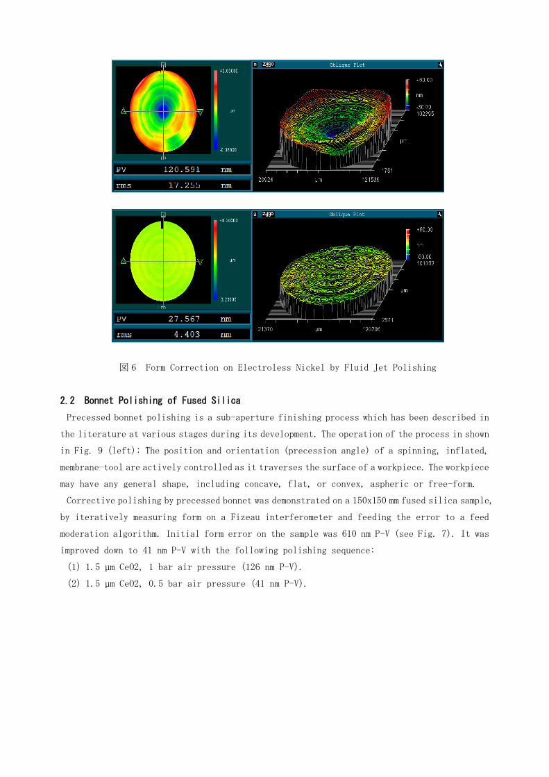
図 6 Form Correction on Electroless Nickel by Fluid Jet Polishing
2.2 Bonnet Polishing of Fused Silica
Precessed bonnet polishing is a sub-aperture finishing process which has been described in
the literature at various stages during its development. The operation of the process in shown
in Fig. 9 (left): The position and orientation (precession angle) of a spinning, inflated,
membrane-tool are actively controlled as it traverses the surface of a workpiece. The workpiece
may have any general shape, including concave, flat, or convex, aspheric or free-form.
Corrective polishing by precessed bonnet was demonstrated on a 150x150 mm fused silica sample,
by iteratively measuring form on a Fizeau interferometer and feeding the error to a feed
moderation algorithm. Initial form error on the sample was 610 nm P-V (see Fig. 7). It was
improved down to 41 nm P-V with the following polishing sequence:
(1) 1.5 µm CeO2, 1 bar air pressure (126 nm P-V).
(2) 1.5 µm CeO2, 0.5 bar air pressure (41 nm P-V).

図 7 Form Correction on Fused Silica by Precessed Bonnet Polishing
2.3 Manufacturing of Parabolic Mandrel (on-going)
A 200x200 mm parabolic section of nominal radius 200mm was precision ground in industry from
a fused silica block (see Fig 8). The ground mandrel was measured with an ultra-accurate UA3P
CMM (at Panasonic in Osaka). The error after grinding was 36 µm. The mandrel is currently
being polished correctively, with the following status having been achieved:
(1) 1.5 µm CeO2, 1 bar, 33% removal target (25 µm P-V).
(2) 1.5 µm CeO2, 1 bar, 85% removal target (3.1 µm P-V).
図 8 Fused Silica block before and after Precision Grinding.
Corrective polishing of this mandrel will carry on until achieving form error below 100 nm
P-V, at which point it will be used for glass slumping trials.

3.Final Super-Smoothing
3.1 Principle of “Continuously Precessed” Bonnet
図 9 Precessed Bonnet (left) and “Continuous Precessing” (right).
Rather than just rely on the usual “single precess” polishing regime described in previous
literature, whereby the tool is precessed in a given direction for each polishing pass, a
novel tool path control method called “continuous precessing” is introduced. In this method,
show in Fig. 9 (right), the direction of the surface tangent used to compute the plane of
precession of the spherical tool is allowed to spin around the centre of the polishing spot.
This method prevents directionality of the polishing marks, as shown in Fig. 10.
図 10 Single (left) and Continuous Precessing (right) across Raster Tool Path.
3.2 Demonstration on Electroless Nickel
The 150 mm diameter sample previously polished by fluid jet was post-finished with the
“continuous precess” method. Very fine slurry of 7 nm fumed silica particles mixed with
pure water at a concentration of 20 g/L was fed above the bonnet with a disposable pipe connected
to a peristaltic pump. To prevent drying and crystallization of the slurry on the work-piece
surface, a series of pure water atomizers were arrayed around the bonnet to keep a high humidity
level inside the polishing enclosure. It was possible to achieve a super-smooth anisotropic
surface below 0.3 nm rms, as shown in Fig. 11 (right).
Spot
Virtualpivot
H-axis
Surface normal

図 11 Surface texture after diamond turning (left), fluid jet polishing (centre), and
continuous precess polishing with 7 nm abrasives (right).
4.Summary or Conclusions
Two process chains have been proposed for replication of thin aspheric mirrors in X-ray
telescopes. But the applicability of these process chains to high energy, high angular
resolution hard X-ray has been held back by lack of an automated method that can correctively
finish aspheric molding dies down to a form error less than 50 nm P-V and super-smooth surface
texture less than 0.3 nm rms. In this paper, a fully automated two-step finishing method
deployed on a common 7-axis CNC platform was demonstrated, that can replace manual finishing.
In the case of the first process chain, fluid jet polishing was used to correctively polish
Electroless Nickel down to 27 nm P-V. In the case of the second process chain, bonnet polishing
was used to correctively polish Fused Silica down to 41nm P-V.
To bring molding dies to final super-smooth finish, a novel polishing method called
“continuous precessing” was introduced, which produces surface texture free from any
directionality. By applying this method with very fine 7 nm slurry, fluid jet polished surfaces
can be improved down to less than 0.3 nm rms.
References
(1) A. Beaucamp and Y. Namba: Corrective Finishing Processes for X-Ray Telescopes after
ASTRO-H, Proc. JSPE International Symposium on Application of Precision Engineering
to Support Next Generation Astronomical Telescopes, Tokyo Institute of Technology,
Tokyo (2013) pp.85-87.
(2) A. Beaucamp, Y. Namba: Super-Smooth Finishing of Diamond Turned Hard X-Ray Molding
Dies by Combined Fluid Jet and Bonnet Polishing, Annals of the CIRP, 62, 1 (2013).
(to be published in July, 2013)
(3) A. Beaucamp, Y. Namba, R. Freeman, Dynamic Multiphase Modeling and Optimization of
Fluid Jet Polishing Process, Annals of the CIRP, 61, 1 (2012) pp.315-318.