development of an onion-set planter based on design
TRANSCRIPT

DEVELOPMENT OF AN ONION-SET PLANTER BASED ON
DESIGN CRITERIA OF PLANT TRANSPLANTERS
by
RAM REDDY SADHU, B.E.
A THESIS
IN
AGRICULTURAL ENGINEERING
Submitted to the Graduate Faculty of Texas Tech University in Partial Fulfillment of the Requirements for
the Degree of
MASTER OF SCIENCE
IN
AGRICULTURAL ENGINEERING
Approved
December, 1982

ACKNOWLEDGMENTS
I am deeply indebted to Dr. Otto B. Schacht for his
direction, guidance, and encouragement throughout this
study. I gratefully acknowledge the encouragement of Dr.
Willie L. Ulich, my graduate advisor, and thank Dr. James
L. Smith for his kind cooperation and suggestions.
I am very much indebted to my parents and friends
for their help and support in attaining this goal. Special
recognition is given to the work and patience of my wife.
11

TABLE OF CONTENTS
ACKNOWLEDGMENTS ii
LIST OF TABLES vi
LIST OF FIGURES vii
I. INTRODUCTION 1
Statement of the Problem 4
Objectives 5
Parameters of the Study 5
Procedural Plan of Study 6
II. PLANTING METHOD AND FUNCTIONS OF THE PLANTER 7
Planting Methods for Producing Onions. 7
Types of Planters 7
Functions of Onion-Set Planters 8
Opening the furrow to the
Proper Depth 8
Metering the Sets 9
Deposit the Sets in the Furrow
in an Acceptable Pattern 9
Covering the Sets with Soil 10
Compact the Soil Around the Sets VJithout Physical Damage
to the Sets 10
Growth of Onions 11
Set Characteristics 12
Germination 12 111

Factors Affecting the Yield of Onions... 14
Soils 14
Seedbed Preparation 15
Cover Crops 16
Fertilizing 16
Varieties of Set-Onions 17
Cultural Practices 17
Planting Method 18
Set Size 20
Planting Rate 20
III. PLANT TRANSPLANTER 22
Design Considerations of
Plant Transplanters 23
Design Considerations 24
Transplanter Operations 25
Furrow Openers 25
Plant Boxes 26
Planting or Plant Carrying
Mechanism 26
Closing Guides 27
Water and/or Fertilizer Feed 28
Presswheels or Press-Plates 28
IV. DESIGN CONSIDERATIONS OF ONION-SET PLANTER 30
Design Criteria 30
IV

V. PLANTER CONSTRUCTION AND COMPONENTS 3 3
Construction 33
Type of Planter 33
Components 34
Supporting Frames 34
Drive System 37
Onion-Set Hopper 38
Metering Mechanism 39
Furrow Openers 4 0
Covering Devices 41
VI. PLANTER OPERATION AND PERFORMANCE 51
Furrow Openers 51
Soil Covering Plates 51
Presswheels 52
Hopper 52
Planting Rate 52
Performance of the Planter 54
Performance Calculations 54
VII. DATA ANALYSIS 59
Test Data 59
Test No. 1 59
Test No. 2 59
Test No. 3 60
Test No. 4 60
Analysis 65
VIII. SUMMARY AND CONCLUSIONS 68
LIST OF REFERENCES 71
V

LIST OF TABLES
TABLE I. NUMBER OF SETS PER FOOT 61
TABLE II. NUMBER OF SETS PER FOOT 62
TABLE III. NUMBER OF SETS PER FOOT 63
TABLE IV. NUMBER OF SETS PER FOOT 64
TABLE V. ANALYSIS 66
VI

LIST OF FIGURES
1. Onion-set planter and its components 35
2. Soil covering plates 42
3. Onion-set planter attached to the tractor 45
4. Onion-set planter, side view 4 6
5. Onion-set planter, front view 47
6. Onion-set planter, rear view 48
7. Onion-set planter, metering mechanism 49
8. Onion-set planter, furrow openers and presswheels 50
Vll
CHAPTER I
INTRODUCTION
Mechanization in agriculture has released millions
of agricultural workers in the industrial sectors, and
has helped contribute remarkably to industrial expansion.
Outstanding developments in agriculture came into existence
after mechanization of a variety of agricultural operations,
Outputs have been increased dramatically, while reducing
levels of manpower and the burdens of the worker. Every
year, demand is increasing for food and fibers and will
continue to increase due to a constantly expanding popu
lation. Increased production is, therefore, required as
cultivable land remains the same. As a result, there is
a need to produce more within the shortest possible period
of time, using minimum manpower and improved cultural
practices.
Many operations in agriculture are now being performed
by machines. This reduces the labor requirements which
have been the principal motivating force in mechanization.
There are some areas, like vegetable transplanting, where
mechanization has progressed very slowly. Transplanters
are particularly advantageous when they can minimize a peak
labor demand. These peaks occur over a relatively short
period of time each year, as in the harvesting of certain

fruits and vegetables. Another important element is that
mechanization improves the ability to produce and deliver
the product for successful marketing of vegetables. A
continuous supply of products into the market has a sig
nificant effect on the economy. Several transplanters
have been developed to plant tobacco, cabbage, sweet pota
toes, tomatoes, rice, and trees for reforestation. The
transplanters are either semiautomatic or automatic. In
semiautomatic machines, the plants are fed by hand into
the plant-placing device. Usually automatic implements
use preloaded plant cartridges or potted plants, stacked
on the planter, which mechanically convey the plant and
place it in the ground. In semiautomatic transplanters,
the labor is partially reduced compared to automatic
machines. Cultural practices for some crops have been
changed to modify growth habits, decreasing required labor
and growing periods.
This present study is related to the development of
a planting machine that can plant onion-sets instead of
planting plants or sowing seeds into the soil. The terms,
"set" or "onion-sets" in this thesis are applicable to a
small onion bulb, usually less than an inch in diameter,
which is used for propagation.
The onion is a major vegetable used in many different
ways in daily diet. The demand for onions is worldwide.
Its use is not limited to any climate or associated with

any nationality; and, they are probably grown in as many
areas of the world as any cultivated crop. Onions are
found in most markets of the world in any season of the
year. Although they are consumed in rather small quanti
ties by most families, they are used in many homes almost
daily. Primarily, they are used as a seasoning for a wide
variety of dishes. The demand for onions is fairly constant
throughout the year: onions are consumed in about the same
amounts when the prices are high or low. It is possible to
predict rather closely the amount of onions that any market
will absorb. It seems impossible, however, to regulate the
flow of onions into market channels where the consumer can
purchase onions at a reasonable price and where the grower
can make a reasonable profit. A year of over-production
and low prices is usually followed by a year of under
production and high prices. One way to resolve this prob
lem is mechanizing the cultural practices of onions. All
current methods of producing onions depend heavily on manual
labor. Though onions are an essential vegetable used every
day, it is unfortunate that not much development has been
made in mechanizing cultural practices in onion production.
Mechanization will lead to a reduction of labor demand that
occurs over a relatively short period of time each growing
season. Uniform rate of production, availability of
product, and high yields are other advantages of mechani-

zation. The reasons for lack of advancement may be due
to the following:
1. Varied physical, mechanical and biological
characteristics of onions and onion plants
are too delicate and perishable for mechani
cal transplanting
2. The delicate and perishable properties of
onion-sets when mechanically handled
3. Lack of development of a new machine
4. Lack of investigation of the effects of a
machine or a mechanized system upon onion
crop production and/or economics
5. Lack of research studies of fundamental
problems related to soil/onion relation
ships
6. Lack of studies relating the adaptability
of machines to onion production, and
7. Cultural practices vary with variety of
onion, production, location, and level of
technology.
Statement of the Problem
A survey of the literature on planting onion-sets
revealed no information pertaining to an implement. There
was a lack of design information for planters, even though
5 5 5
hand planting is a tedious and costly operation. This
study was initiated because of the desirability to replace
and to establish uniform rates of production throughout
the year at a lower planting cost.
Objectives
The primary objectives of this study were:
1. To investigate current methods of planting and
producing onions
2. To analyze the design considerations for mechani
cally planting onion-sets in relation to trans
planters
3. To develop a planter to plant onion-sets without
damage to the sets
4. To field test the onion-set planter's perfor
mance and to evaluate the resulting data.
Parameters of the Study
This study consisted of a review of literature per
taining to planting onion-sets. A review of uses of trans
planters for such a purpose was then conducted. In addi
tion, data pertinent to the planter design were set up by
a literature review and by consultations with other re
searchers .

Procedural Plan of Study
Initially, considerable literature was reviewed to
establish a background to develop a mechanical planter to
plant onion-sets. Although onion planters were mentioned
in the literature, no specific information was found. The
objectives of this study, the parameters of the study, and
an organizational plan were developed using consultation
and review. As there was no published information avail
able on planting sets, it was necessary to establish ini
tial design criteria. A review of related materials was
necessary, however, to establish a basis for the design
of an onion-set planter.
A working model was to be developed and constructed
based on formulated design criteria. It was decided to
conduct performance tests of the model and to modify it
accordingly, if necessary. The documentation of informa
tion gathered, the development of the implement designed,
and the results of the tests performed follow.

CHAPTER II
PLANTING METHOD AND FUNCTIONS OF THE PLANTER
Planting Methods for Producing Onions
1. Sowing seed directly in the field where the crop
is grown
2. Sowing seed in a seedbed from which the plants
will be transplanted later to the growing field
3. Sowing seed in a seedbed from which sets are
planted later into the growing field.
Farmers may grow onions from seeds or by plants,
but this paper deals only with growing by planting onion-
sets. The importance of mechanically planting sets is due
mainly to the fact that this is one of the surest and
easiest methods of producing green onions or large bulbs
at a minimum planting cost (Walker 1944).
Types of Planters
Planting and seeding equipment may be divided into
four major types:
1. Row crop planters - used for planting crops such
as corn or grain sorghums
2. Grain drill and air seeders - used for planting
small grain
3. Broadcast seeders - used for planting grains and
grass
4. Specialized planters.
g
The onion-set planter falls in the row-crop planter
category, but in a special type used only for planting
bulb-type sets. Row-crop planters are designed for various
planting operations, and differ considerably in row widths,
method of metering, method of furrow opening, type of seed
placing mechanism, and covering methods.
Functions of Onion-Set Planter
The purpose of the onion-set planter is to plant sets
evenly in a furrow. To do this in the desired manner, the
planter must perform a number of important functions. The
planter must: (1) open the furrow to the proper depth,
(2) meter the sets, (3) deposit the sets in the furrow in
an acceptable pattern, (4) cover the sets with soil, and
(5) compact the soil around the sets without physical
damage to the sets.
Opening the Furrow to the Proper Depth
For adequate germination, the sets must be placed below
the surface of the soil; therefore, the planter must have a
device for opening the soil. Furrow openers may be: shovel
openers; shoes; runners; or wheel openers. The furrow
opener must maintain the seed furrow at uniform and proper
depth in a variety of soil conditions. If the sets are
planted too shallow or too deep, they may not germinate be
cause the environmental conditions may be poor (Shoemaker 1947]

Metering the Sets
A controlled planting rate, such as a prescribed
number of sets per acre (hectare), bushels per acre
(liters per hectare) or pounds per acre (kilograms per
hectare) is desired when planting the crop to obtain the
optimum yield. Metering is considered to be one of the
major functions of a planter. A precision seed metering
device or mechanism is necessary to allow one set at a
time to be metered and placed in the soil.
Deposit the Sets in the Furrow in an Acceptable Pattern
Depth and space between the sets greatly affect the
yield of a crop (Colby et al. 1944). Yield is affected because
placement has a bearing on emerged plant population. When
sets are properly placed in a well-prepared seedbed, a higher
percentage will grow; more plants can be expected to emerge
under normal growing conditions.
The planter should be able to perform uniform seed
placement in uneven soil conditions. The furrow opener on
the planter may have spring-loaded mechanisms to ride over
irregularities and place the sets at a desired uniform
depth. Seed placement mechanisms, such as a seed tube
and power drop device, are essential to deliver seeds to
the furrow opener.

10
The other requirement is placement of one set in
relation to another or to fertilizer. Sets may not grow
if placed in contact with high concentrations of ferti
lizer. Therefore, the planter must be designed to place
the seed and fertilizer (if necessary) so they will not
come in contact.
Covering the Sets with Soil
Another major function of a planter is covering the
onion-sets. Covering the sets can be accomplished through
the use of knife covers, disk covers or covering plates.
On some planters, the presswheel serves as the covering
mechanism. Shallow covering of sets leads to exposure to
the atmospheric conditions and fewer sets growing properly.
Covering too deep delays emergence of the onion plant and
lengthens the growing period.
Compact the Soil Around the Sets Without Physical Damage to the Sets
Usually, compacting or firming the seedbed around the
sets is done by a presswheel running atop the furrow. Some
important characteristics of presswheels are as follows:
Diameter. It has been found that an 8-inch diameter
presswheel is optimum for crop planting (Richey et al. 1961)
When a smaller wheel is used, the pressing angle is greater

11
than for a larger diameter wheel and the possibility of
disposition of sets in the furrow would increase. On the
other extreme, a larger wheel cannot be used because of
the space available between the furrow opener and the
drive wheel.
Width of Rim. Research has shown a one-inch width
of rim, rubber covered, to be the best for crop planting
(Richey et al. 1961). A very narrow presswheel allows
overcompaction to occur due to excessive pressure. This
results in reduced production. Wider rims reduce compac
tion and again production can be significantly affected.
Pressure Mechanism Against the Soil. There should
be provision for manipulating the pressure applied to
match soil conditions. This will protect the seed or sets
from overcompaction or undercompaction. Spring force ad
justment or lever arm adjustment are two common methods of
changing the pressure applied from the pressure wheel to
the soil for a given wheel diameter and rim width.
Growth of Onions
Modern crop farming depends on using high quality
sets. The set variety and growing percentage and purity
of seed should be known before use. A producer cannot
harvest a better crop than the sets planted. Therefore,
the use of good sets is the first step in increasing
crop yield.

12 Set Characteristics
1. Sets that will produce plants adapted to the
climate and soil where grown
2. Sets that are free of disease
3. Sets that will have a higher rate of germination.
Germination
Apart from the set quality, there are four basic en
vironmental conditions which affect set viability.
1. Moisture. Because onions are shallow-rooted,
they require abundant moisture near the surface, especially
during early growth (Ware and McCollum 1959). Normally,
new roots are formed throughout most of the growing season.
They arise from the stem plate at the base of the onion
plant; but they are not formed unless the stem plate is in
moist soil.
2. Oxygen. Oxygen is required for germination, but
is usually limiting only when the soil around the sets is
saturated with water. This is a problem particularly
when rainwater floods into the furrow. This condition
removes all the oxygen from the soil and, if the area
remains flooded, the onion-sets will be killed. It is
not the excess of water that kills the sets, but the lack
of oxygen.

13
3. Temperature. The effect of temperature on
germination has received much attention (MacGillivray 1953).
Temperature and length of the day are controlling factors
in the successful production of onions. The best root
development occurs when the soil temperatures range from
55° to 75°F.
4. Planting Depth. Researchers have varying opinions
on planting depth. Mr. Baggerman (1981) suggested that in
his research on onion production, a planting depth of between
1.5 to 2 times the diameter of the sets was appropriate.
J. S. Vandermark (1977) reported in his article that dry
onion-sets should be planted one-inch deep in rows between
12 to 14 inches apart, with the sets two-inches apart, to
produce onions. To produce green onions, larger size sets
(one-inch) are planted in rows 12 to 24 inches apart (close
enough to touch each other) and one and one-half inches
deep. Once the tops are six-inches high, they can be used
as green onions.
The factors that influence the growth and emergence
of the onion-set can be listed as follows (Smith 1965):
1. Quality of sets planted
2. Viability of the sets
3. Treatment of the sets with chemicals to kill
soil microorganisms
4. Uniformity of the set size

14
5. Planting depth and rate
6. Type of soil
7. Moisture content of the soil
8. Type of seed-dropping mechanism
9. Uniformity of distribution of the sets
10. Type of furrow opener
11. Prevention of loose soil from getting under the sets
12. Uniformity of coverage
13. Type of covering device
14. Degree of pressing and firming of the soil
around the sets
15. Cleanliness and condition of seedbed
16. Time of planting in relation to season
17. Temperature of soil
18. Type of drainage
19. Condition of soil crusts
20. The good judgment skill and attention of the
planter operator.
Soils
Factors Affecting the Yield of Onions
According to W. G. Colby et al. (1945), fine or very fine
dandy-loom soils are very suitable for onions. Such soils
are deep, well-drained and fairly retentive of moisture,
and workable soon after frost. The last point is important
because onions are essentially a cool season crop and early

15
planting is necessary in securing high yields. Onions can
probably be grown more satisfactorily from sets on light
soils than from seed. The growing season of the former is
shorter and maturity and subsequent harvest are accomplished
before the hot, dry weather of late summer occurs.
Seedbed Preparation
Most farmers prefer to plow their onion land in the
fall to facilitate early spring planting operations. There
is also the prevailing opinion among growers that fall-
plowed land maintains better moisture relationships during
summer dry periods (Colby et al. 1945). The top soil of
fall-plowed fields tends to blow less during the period
between the planting of the set and the time top growth
is sufficient to afford protection from the wind.
Just as soon as the soil can be worked in the spring,
it is thoroughly disced and then harrowed twice to produce
a finely pulverized seedbed with a smooth, level surface.
Some difficulty may be experienced when granular
fertilizer is applied after seedbed preparation. As soil
is worked following fertilizer application, the harrowing
operations tend to concentrate the fertilizer in the two
trenches left by the rear wheels. This occasionally re
sults in some injury to the crop. The possibility of
trouble can be reduced if lightweight tractors are used

16
for the final seedbed-preparation operation, and if re
peated working of the soil after fertilization is avoided.
Cover Crops
According to the survey conducted by Colby et al.
(1945) it was clear that cover crops will protect the onion
crop from wind erosion. Because of their earlier maturity,
onions produced from sets can be followed with a cover
crop more satisfactorily than onions produced from seed.
Difficulties still exist in disposing of the winter cover
in the spring. If suitable cover crops are to be fully
effective in curtailing wind and water erosion and in
accomplishing all the other beneficial effects ascribed
to them, cover crops should remain on the land over
winter.
Fertilizing
A common practice in fertilizer application is to
broadcast all of it prior to planting (Colby et al. 1945).
Another method is to plow the fertilizer into the soil
beneath the surface. Both methods have been compared by
the researchers and in long term no significant differences
were found. It can be concluded that fertilizing during
planting is not necessary. This aspect was not considered
in this study.

Varieties of Set-Onions
The Ebenezer variety, commonly called Japanese, pro
duces a semi-flattened onion of good size, with a medium
yellow skin. The crop can be grown from sets, matures
early, yields are usually good, and, if harvested under
favorable conditions, they keep well in storage.
Globe onions are increasing in acreage grown from
sets. They have become popular because of their high
yields and excellent storage qualities. Globe sets are
sold under different names—Golden Globe, Golden Marvel,
Connecticut Yellow Globe, and just Yellow Globe. In gen
eral. Globe onions have a round bulb with heavy, yellow
skin. When satisfactory growing and harvesting conditions
prevail. Globe onions will out-yield Ebenezer onions and
keep better in storage.
Each year new varieties of onions are developed, and
research is being carried out to determine their growing
characteristics, production capabilities, and storage
properties (Baggerman 1981). Some of the more recent
varieties are the Grano, Early Grano, Ringmaster, Yellow
Grano, Yellow Burmuda, and Sweet Spanish.
Cultural Practices
The common practice of planting onions has been by
hand. The labor requirements for growing an acre of
onions is high, but cash returns are also high. Since
17

18
labor has historically been plentiful, little attention has
been given to labor-saving methods. The present situation
of low availability and high cost of labor has made the
development of a planting machine much more feasible.
Attempts made in previous years for planting onion-
sets did not reveal any specific information about onion-
set planters. It was mentioned by a few authors in their
publications (Colby et al. 1945; Jones and Mann 1963) that
some trials were made using crude onion-set planters.
Planting Method
As mentioned by Colby et al. (1945), machine methods
have introduced some problems compared with hand planting.
The analysis of the problems is essential for a discussion
of the development of a new onion-set planter.
The methods for planting sets have been found to ma
terially affect the yield of onions. Hand planting, al
though slow and laborious, results in the largest yields.
Machine planting in which a set planter distributes the
sets along one or two rows is much faster and also easier,
but yields have been lower.
In a trial conducted by the Massachusetts Experiment
Station in 1941, a relatively dry season, machine-planted
sets yielded at a rate of 500 fifty-pound bags of onions
to the acre as compared with 7 60 bags from hand-planted

19
sets. The lower yields from machine-planted sets was
largely due to the failure of set planters to space the
sets evenly in the row and to place them uniformly in
an upright position.
The importance of placing sets in an upright or
nearly upright position was studied by another experi
ment which was carried out in the same year by the
Massachusetts Experiment Station. Sets which were all
planted horizontally yielded 75 percent as much as sets
which were all placed upright; sets which were completely
inverted yielded only 20 percent as much.
The growth of sets placed randomly by a machine
varies with the weather conditions immediately after
planting. If the weather is dry, reductions in yield
may be considerable. If sufficient moisture is present,
a good crop may result even if some sets are not placed
in the optimum position.
In the past, most growers who used machine planters
followed the machine with a crew who properly spaced the
sets, removed excess sets, and filled in spaces missed.
The use of carefully graded sets when machine planting
(a practice adopted by some producers) improved the place
ment accuracy of the machines.
An efficient planter is a great help to the grower
with a large onion acreage. One man with a two-row
planter can cover five or more acres in a day, compared

20
with only one acre planted by ten hand workers (Colby et al.
1945). The greater speed of mechanical planters enables the
grower to get his sets planted quickly whenever the change
able April and early May weather permits. More significant
is the lower cost of production with machine planting. The
savings in production costs more than offset the loss from
reduced yields (Baggerman 1981).
Set Size
Colby et al. (1945) determined that maximum yields of
marketable onions were obtained when sets ranging from 0.5
to 0.75 inches in diameter were spaced 2.25 to 2.5 inches
apart in 13 to 14-inch row widths. Problems exist when
using sets of a larger size than the 0.75-inch diameter.
These include, an increased number of "bolters" or onions
producing seed stalks and an increase in number of bushels
of sets required to plant a given area.
Planting Rate
Through the literature review, it was learned that
the quantity of sets required to plant an acre is deter
mined mainly by the size of the sets used, the distance
between the rows, and the spacing of the sets in the rows.

21
The quantity of onion sets required to plant an acre
is documented below for different spacings and different
sizes of sets (Colby et al. 1945).
BUSHELS REQUIRED TO PLANT AN ACRE
ROW SPACING (INCHES)
12 14 16 Size of Spacing in Row Spacing in Row Spacing in Row Sets (Inches) (Inches) (Inches)
(Inches) 2.5 3.0 3.5 2.5 3.0 3.5 2.5 3.0 3.5
0 . 5
0 . 6 2 5
0 . 7 5
0 . 8 7 5
1
21.0
34.0
56 .0
75.5
112.5
17.5
28.0
46.5
65.5
94.0
15.0
24.0
40.0
56.0
80.5
18.0
29.0
48.0
68.0
96.5
15.0
24.0
40.0
56.0
80.5
13.0
20.5
34.5
48.0
69.0
16.0
25.5
42.0
58.5
84.5
13.5
21.0
35.0
49.0
70.5
11.5
18.0
30.0
42.0
60.5
(Illustration by Colby, W. G., Gilgut, C. J., and Yeagian, H.M., "The Culture of Set Onions in the Connecticut Valley.")

CHAPTER III
PLANT TRANSPLANTER
The operation of transplanting has not been completely
mechanized. Vegetable crops, such as tomato, celery and
cabbage, as well as field crops such as tobacco and rice
have the common requirement that they must be transplanted
into the field. The transplanting operation requires a
considerable amount of hand labor in pulling of the plants
and setting them in the field. The results of transplanting
are also not always satisfactory, in that stands may suffer
high mortality or nonuniformity of growth. Reliable auto
mation of transplanting operations also becomes important
as labor costs rise. Huang and Splinter (1968) have studied
the transplanting and subsequent growth of tobacco and cab
bage and reported the following disadvantages for conven
tional transplanting:
1. High labor requirement in a short period of time
2. Weather often causes farmers to miss the best
transplanting period, thus resulting in reduced
yield
3. During the transplanting operation, plant losses
are to be expected and the missing plants need
to be reset; therefore, extra labor is required
22

4. Unavoidable human error results in nonuniformity
of stands and missing plants which consequently
affects mechanical harvesting.
Another study showed that human error increases expo
nentially with planting rate and, from a human engineering
standpoint, the transplanting speed should be limited to
less than 1.5 mph (Splinter and Sugg 1959).
Salter et al. (1979) found that transplanting also
causes plant damage especially to the root system. This
occurs in moving from the greenhouse bed or seed tray to
the growing field. This is because the plant and its root
system lose water by transpiration. The damaged roots are
unable to absorb enough water from the soil to regain their
loss. This results in the plant becoming weak and it can
not produce its own food material. Thus, its growth is
temporarily reduced, and maturity is delayed, causing
normally less yield.
Design Considerations of Plant Transplanters
Some kinds of crops, including tobacco, cabbage, sweet
potatoes, and tomatoes, may be propagated in special beds
and then transplanted into the field. If an appreciable
area is involved, mechanical aids are usually employed.
Mechanical plant setters are also suitable for planting
small trees in reforestation work and for other kinds of
nursery stock.
23

24
These machines, with the assistance of an operator,
place young plants into the machine-made furrow. Water
and fertilizer are sometimes accurately metered close to
the plant roots to assist in an early growth of the trans
plants .
Design Considerations
In developing a gravity-type transplanter, the
following features are to be considered:
1.. Semi-automatic feeding mechanism for the plants
(optional for automatic transplanters only)
to carry and feed a considerable number of
plants on the transplanter and drop them to
the ground
2. Maintain the transplant in a near vertical
position, both during and after planting
3. Maintain uniform depth and width of furrow
to avoid cramping the plant roots
4. Provide water and fertilizer feeding systems
5. Presswheels that do not destroy the root system
if bare transplants are used
6. Type of transplant, its size and root charac
teristics
7. Plant spacing

25
8. Seating arrangement on semi-automatic transplanters
should be as near the furrow as possible
9. Signals for placement of the plants at proper
locations
10. Forward speed of the implement.
Transplanter Operations
Transplanters perform the same basic operations as other
planting machines. These are: (1) opening the furrow, (2)
metering the plant, (3) placing the plant, (4) feeding water
or fertilizer (optional), (5) covering the plant with soil,
and (6) firming the soil around the plant.
The basic and unique components of the transplanter
and its functions are explained below.
Furrow Openers
The furrow opener forces the soil sideways, opening a
furrow for the plant. The width and depth of the furrow
depends upon the design of the shoe, the desired depth of
operation, and type of the transplant. Usually, planting
depth is controlled in relation to the size of plants
being transplanted. Machines designed for setting plants
in prepared seedbeds are generally equipped with runner-
type furrow openers. The principal requirements are that
the furrow be of uniform depth and that it be wide enough
to accommodate the plant roots without crowding.

26
Some openers, especially those used for planting big
size plants for forestation, have a conventional v-shape
and leave a wide enough furrow to avoid cramping the plant
roots.
Plant Boxes
The plant box holds the transplants during the
planting operation. Conventional-type transplanters have
two operators per row, and they hand-feed the plants into
the furrow from the plant box.
Planting or Plant Carrying Mechanism
Some transplanting machines will have mechanical
transfer devices that are hand-fed but which automatically
place the plants in the furrow. This arrangement allows
the operators to work in more comfortable positions and
tends to give more uniform placement in the furrow. The
transfer device must be carefully designed to ensure that
the plants will not be damaged and that the possibility
of injury to the operator be minimized. Proper timing
is also required, so that the plants will remain upright
as the roots are covered.
Another kind of machine has plant pockets, attached
to a conveyor chain, which transport the transplants to
27
the furrow. These pockets are spring-loaded and have a
v-shape that forms a holder for the transplants. The
operator places a transplant in each pocket as it travels
over the top sprocket of the conveyor chain.
To prevent damage to the transplants, each pocket is
equipped with a rubber gripper on the inside. The con
veyor chain carries the plant pockets through the plant
ing cycle. The number of pockets or size of sprockets will
vary the planting rate or distance between transplants
in the row. A rotating disc is sometimes used to replace
the conveyor chain. The pocket arms on this unit are
stiffer because they are bolted to the rotating disc. In
this case, the number of pockets bolted to the disc
determines the transplant spacing in the row.
Closing Guides
As pockets or holders containing a transplant begin
to travel downward, they pass through a channel called
closing guides. The function of the closing guides is to
close or compress the v-shaped pocket around the plant.
In the closed position, the plants are held tightly, but
gently, by the pocket and rubber gripper insert.

28
The closed pockets then move with the conveyor chain,
disc, or other mechanism into the furrow. As the pocket
opens, it releases the transplant and it is set into the
furrow.
Water and/or Fertilizer Feed
The next process in the transplanting operation is
sometimes the addition of water to the furrow at the point
where the transplants are placed. This is usually accom
plished with valves. Storage tanks for water and fertili
zer (if necessary) are mounted on the implement or tractor,
and the delivery tubes are run through a control valve to
the release point. A trip mechanism, called the water trip
and/or fertilizer trip, trips or activates the valve and
the fluid is released into the furrow. The water aids the
plant in establishing its root system, thus getting a good
growth start. A starter fertilizer solution may be mixed
with the water to aid in getting the plant off to an even
faster start.
Presswheels or Press-Plates
The soil is closed and packed around the transplants
by presswheels or press-plates in the case of loose sandy
soils. Presswheels are used in pairs, pitched and angled
for the most efficient action. In some cases, these wheels

29
have tilted rims or the wheels are tilted between 20 to
45 degrees to the soil surface to force more soil around
the plants. The furrow-opener depth may be gauged by the
presswheels or press-plate setting, with the entire assem
bly floating as a unit and being lifted for turning.
Another kind of design controls the opener depth by the
transport wheels and uses spring-pressure to control the
degree of packing. Presswheels serve tv;o functions. First,
they pack the soil firmly around the plant; second, they
may serve as the drive mechanism for the planting unit,
the plant conveying mechanism.

CHAPTER IV
DESIGN CONSIDERATIONS OF ONION-SET PLANTER
Design considerations of onion-set planting include
the rate of planting, spacing, planting depth, row width,
and forward speed.
Design Criteria
The following design criteria for an onion-set planter
were determined after discussions with Dr. Otto B. Schacht
(1981) and Mr. Franklin Baggerman (1981):
1. Use of pregraded onion-sets
2. Uniform rate of planting and uniform distribution
of sets
3. Free gravity flow of onions
4. Easy adjustment of all components of the planter
to control the planting rate, width, and depth
5. Opening the furrow
6. Covering the onion-sets with soil
7. Firming the soil without damaging the sets
8. Avoid injury to onion-sets throughout the planting
operation
9. Design simplicity
10. standardization
11. Product safety.
30

31
Previous researchers (Colby et al. 1945; Splittstoesser
1979; Vandermark 1977) determined the optimum size of sets in
regard to germination, high yields and other aspects. The
most common sizes used are 0.25-inch to 0.375-inch (small),
0.5-inch to 0.75-inch (regular), and 0.75-inch to 0.875-inch
(oversize). The sizes selected for use in this research
work was 0.5-inch to 0.75-inch. This is the most common
available size.
A uniform rate of planting is essential for maximum crop
yield. The literature review indicated that the spacing in
the rows of 2.25-inch to 2.5-inch was optimum (Colby, et al.
1945). Planting depth for onion-sets usually varies with
the diameter of the set. The common practice is to use a
planting depth that is two times the diameter of the set,
i.e., depth of planting may vary between 1 inch and 1.5-
inch. J. S. Vandermark (1977), a vegetable crop specialist,
suggested a planting depth of 1 inch. The planter developed
for this research can be adjusted to open the furrow up to
a 3-inch depth.
The importance of free gravity flow of onions is essen
tial to avoid missing sets while planting, due to the clog
ging or other obstruction in the movement of sets during
the planting operation. This planter creates a centrifugal
force on the sets in the bottom layer of the hopper. The
onion-sets flow downward from the metering device to the
furrow through a drop chute. The details of the components
are discussed later under planter construction and components.

32 Protection from injury to the sets is an important
factor in regard to their growth. Damage should be avoided
at every stage of onion set movement during the planting
operation.
Easy adjustments, like controlling the flow of onion-
sets, row width, planting depth, covering with soil, and
pressure from the presswheel are important considerations.
Relieving the stresses within the planter, when coupled to
the tool bar, is essential for least friction performance of
the planter.
In the overall design, simplicity, standardization of
parts, and product safety, were considered an important cri
teria. This would allow for manufacturing with fewer com
plications due to non-standard parts or sophisticated fabri
cation methods. Safety of operation is essential to prevent
injury to the operator.

CHAPTER V
PLANTER CONSTRUCTION AND COMPONENTS
A planter was designed and constructed for the special
purpose of planting onion-sets. The sets are grown from
seed sown thickly enough to produce only stunted bulbs or
sets. After being cured, the sets can be stored for long
periods and used to produce green onions or mature bulbs
(Walker 1944) . Approximately 1 to 2 million bushels of
sets are utilized annually in the United States. The terms,
"onion-sets" or "sets", are used in this study to refer to
the small bulbs.
Construction
Type of Planter
The onion-set planter developed in this study was a
tractor-mounted, horizontal plate, row-crop planter (Figs.
1, 3 through 8). Sets were dropped in a row approximately
2 to 2.5-inches apart. This spacing depended upon the dia
meter of the sets and the plant population desired. The
common method of planting onion-sets is either one row or
two rows per bed. For this study a two-row per bed config
uration was chosen as it was the most prevalent in the
immediate region (Baggerman 1981).
33

34
Components
The major components of the planter as constructed were:
1. Supporting frame
2. Drive system
3. Onion-set hopper
4. Metering mechanism
5. Onion-set placement mechanism
6. Furrow openers
7. Covering devices.
Supporting Frames
The planter design consisted of three different sets of
supporting frames. The main frame [20] in Figure 1 supports
the total implement and was attached to the tool bar. The
joint between the frame and tool bar was rigid. The tool bar
was attached to the three point hitch of the tractor, which
allowed lifting, leveling adjustments, lateral adjustments,
and primary depth control. The two furrow openers [12] and
two presswheels [13] were attached to the main supporting
frame.
The second supporting frame, [18] of Figure 1, was bent
in a parabolic shape for half of its length and welded to a
straight portion which was connected to the main frame. The
front end was attached with a hinge joint to the main frame,
while the rear end was supported by the drive wheel hub

35
Q © 0 0 ® © ®

36
Legend for Figure 1
[1] Hopper
[2] Outer shell of hopper
[3] Cone agitator
[4] Outlet opening
[5] Horizontal plate
[6] Idlers
[7] Driven sprocket
[8] Drive sprocket
[9] Drive wheel
[10] Conical drop chute
[11] Ribbon-type delivery tube
[12] Furrow opener
[13] Presswheel
[14] Soil covering plate
[15] Adjustable brackets
[16] Hopper supporting frame
[17] Detachable drive chain
[18] Supporting frame for drive and hopper
[19] Tie rods
[20] Main supporting frame
[21] Hub connector
[22] Furrow opener support
[23] Tool bar

37
connections [21]. The planter was constructed of medium
carbon steel flats in the shape of a fork. Provision was
made between the frames [18] and hub connector [21] to adjust
the length of the drive chain [17]. A third set of supporting
frames [16] held the hopper [1] connecting the outer shell [12]
of the hopper and the frame [18]. The hopper supporting frame
[16] contained four members made of steel flats; two suppor
ting the front and two supporting the back of the hopper.
The frame [18] held the drive wheel, idler wheels, and
onion-set metering mechanism away from the hopper to facili
tate freer rotation of the horizontal plate [5].
Drive System
The drive system for this planter consisted of a drive
wheel which attained motion when the planter was pulled by
the tractor. Drive wheel motion was transmitted to the
metering mechanism through a two-sprocket, one-chain drive
sprocket fitted to the wheel shaft and another to the meter
ing mechanism shaft. The mean diameter of the drive sprocket
[8] was 2.5 inches with 6 teeth, and the driven sprocket had
a mean diameter of 4.5 inches and 12 teeth. This gave a
speed reduction ratio of 1:0.5 . The chain used was No. 55,
pressed steel, detachable-link type. This is a simple, low-
cost chain for slow speeds (also occasionally referred to
as a "plain chain"). The links are of steel or cast iron
and are easily replaceable. One end of the link is the

38
hook end and the other the plain end. This is the least
expensive type of chain and is well-suited for moderate
loads at speeds not exceeding 400 to 500 ft/min. Lubrica
tion is not recommended as the lubricant would tend to re
tain grit particles in the joint. This was an improved
type of steel detachable-link chain, which had one-third
more tensile strength than conventional steel detachable
chain, and more than twice the fatigue strength (Thuerman
and Paul 1956). Tight joints which often develop in stan
dard double-pitch roller chain were avoided with such a
chain.
Onion-Set Hopper
The onion-set hopper [1] was a vertical, cylindrical
shell mounted coaxially above the metering mechanism. It
consisted of an outer shell [2] fitted around the outside
at the bottom. This left an annular space between the two
cylinders. The annular space was utilized as a passage to
guide the onion-sets into the drop chute during operation.
There were two guide plates in the annular space, fixed
to the inner cylinder, adjacent to the outlet openings,
so that the flow of onions was diverted into the drop
chutes. The guide plates were located diametrically and
tangentially to the inner cylinder [1] at the bottom.
Space was left between the guide plates and the horizontal
plate [15] to allow complete rotation.

39
A cone agitator was coaxially mounted above the meter
ing mechanism and inside the cylinder. This agitated the
onion-sets and moved them toward the peripheral gap between
the inner cylinder and the horizontal plate. This gap was
provided by raising the inner cylinder above the horizontal
plate through cleat supports fixed between the shells. To
control flow further, a gap was provided by a circular ad
justable ring fixed around the outside of the inner cylinder.
This ring's position could be varied by two vertical bolts
fitted on either side of the inner shell [1]. These bolts
were supported from the cleats between the two shells.
Metering Mechanism
The metering mechanism was driven by the drive wheel [9]
while the planter was in motion, through the chain [17] and
sprockets [7 and 8]. Sprocket [7] was mounted on one end
of a 0.75-inch diameter shaft. A straight end bevel gear
of 11 teeth with an overall diameter of 2 inches was fixed
on the other end. This bevel gear was coupled v;ith a hori
zontal bevel gear of 40 teeth with an overall diameter of 6
inches. Rotation in the vertical plane was converted to
rotation in the horizontal plane by this bevel gear drive.
The horizontal bevel gear transmitted its rotation to the
horizontal plate [5] through a ratchet arrangement that
allowed for easy removal of the shells from the main frame.
Rotary motion of the horizontal plate initiated the movement

40
of onion-sets and initiated the flow of onion-sets into
the drop chutes from the annular space.
Furrow Openers
The optimum depth for planting varies widely with
different onion sizes and is also influenced by soil mois
ture conditions, soil temperature, time of year, forward
speed of the implement, and type of opener used. Growth
properties are also influenced by environmental conditions,
and this requires careful control of the planting depth.
A curved-type chisel opener [12] with spring pressure [9]
was selected for this planter. The opener was 2-inches
wide and had a 30° tip angle at the chisel end. The
bearing area was moderately low and helped in shearing the
soil easily. These openers [12], shown in Figure 1, were
attached to 1-inch diameter, solid carbon steel rods. Flat
steel plates were used to connect the rods. The rods were
sandwiched between the plates by means of bolts and nuts.
Slots in the upper end of the plates allowed for fine adjust
ment of the depth of the furrow openers. The brackets [15]
were used for coarse adjustment of the openers. The furrow
opener system was fixed to the main supporting frame through
a steel flat plate welded horizontally to the frame [20].
The adjustable brackets [15] allowed for adjusting the row
width of the furrow openers. At the rear of each furrow
opener, a round bracket was provided to hold the metallic

41 ribbon-type drop tube [11]. The drop tube transferred
the onion-sets from the metering mechanism to the center
of the furrow immediately behind the furrow openers. This
transfer was accomplished by gravity flow through the tubes.
Covering Devices
Good set-to-soil contact is essential for growth and
plant emergence. To ensure that the sets were in contact
with the soil and that the sets were not lying in a void or
air space, the seedbed had to be well prepared. In addi
tion, fine particles of soil should be used to cover the
seed. The covering device should place moist soil in con
tact with the sets, press the soil firmly around the sets,
cover them to the proper depth and yet leave the soil di
rectly above the row loose enough to minimize crusting and
promote easy emergence. For proper growth the sets must be
in contact with moist soil and covered with a layer of soil
which the plant can penetrate. Insufficient moisture will
delay growth, while too thick a covering layer or a hard-
crusted layer can cause the plant to die. Even though sets
vary greatly in their requirements, the soil type, soil
conditions at planting, and climate also affect covering
practices.
The set covering effectiveness can be determined by
examining the condition of the seedbed after planting.

42 A partial groove left may indicate one of the following
conditions:
1. Need for a covering device
2. Covering device needs to be adjusted
3. A different type of covering device should be
installed.
Covering plates used for this planter were shovel-
type, bent inward to close the furrow. Two such plates
(Fig. 2) were used for each furrow or row. These were
made of 0.1875-inch thick carbon steel sheet, conveniently
bent to cover the sets in the furrow. The plates were
fixed to the rear of each furrow opener by means of butter
fly nuts and could be rotated upward and downward. This
attachment allowed for ease of removal so that the operator
could allow the sets to remain uncovered in the furrow to
facilitate counting the number of sets distributed and their
relative positions.
Plan
Elevation
Fig. 2. Soil covering plates

43
Presswheels compact the soil around the onion-sets,
facilitating the rise of capillary moisture and pushing some
soil over the furrow for covering. They may also act as
gauge wheels to hold the openers at a constant depth over
uneven ground. It has been found that a presswheel with a
rubber-covered rim about 1-inch wide and 8-inches in diameter
is an aid to germination in the areas where soil moisture is
low (Richey et al. 1961). Presswheels employed on row crop
planters are open-center, concave or steel presswheels.
Presswheels are commonly used in soil conditions where
obtaining good seed-to-soil contact is not a problem. Rubber
tired wheels, 2-inches wide and 8-inches in diameter [13], were
employed in the onion-set planter. They had an adjustable
height mechanism and were spring-loaded for variable pressure.
Laboratory tests for beans, corn, etc. in Michigan
indicated that in sandy clay loam, pressures of 5 or 10 psi
applied to soil after the planting suppressed emergence;
whereas, the same pressure applied at seed level improved
emergence when adequate moisture was available immediately
below the seeds (Kepner et al. 1978). But, for the onion-
sets, it was determined to use less pressure than was used
for seeds, as the sets have a more perishable texture. The
presswheels used in this case were attached to the main sup
porting frame by means of a solid rod, 1-inch in diameter,
through the adjustable brackets [15] as in the case of fur
row openers.

44 Height and pressure of the presswheel against the soil
could be varied by adjusting the spring-loaded tie rod.
These could also be adjusted with the centerline of the
furrow, as row width varied.

45
Fig. 3. Onion-set planter attached to the tractor

46
Fig. 4. Onion-set planter, side view

47
Fig. 5. Onion-set planter, front view
48
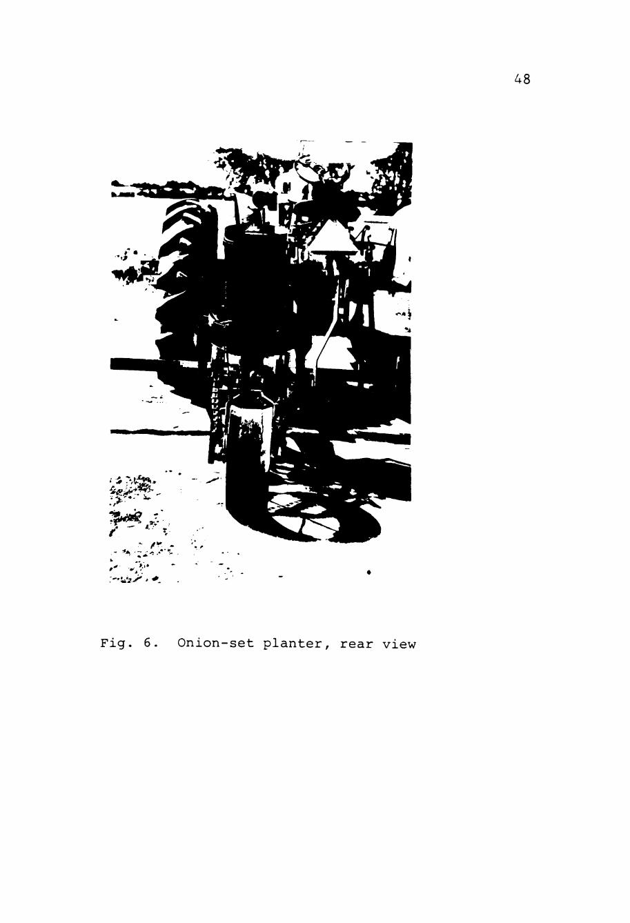
Fig. 6. Onion-set planter, rear view

49
Fig. 7. Onion-set planter, metering mechani sm

50
Fig. 8. Onion-set planter, furrow openers
and presswheels

CHAPTER VI
PLANTER OPERATION AND PERFORMANCE
The planter was coupled to a tool bar which was con
nected to a Ford-900 tractor. This tractor had a hydraulic
lift to raise and lower the tool bar as required by primary
adjustment of the implement. The final adjustment was done
in the field by adjusting the spring-loaded tie rod connec
ting the supporting frames.
Furrow Openers
Furrow openers on both sides of the implement were
adjusted to open the furrow between one and two inches,
depending upon the set size and soil conditions. Recom
mended depths were one inch for 0.25 to 0.50-inch sets
and two inches for 0.50 to 0.75-inch set size.
Soil Covering Plates
These plates were adjusted using the butterfly nuts.
This allowed movement in the vertical plane until the sets
were totally covered with loose soil. For experimental
purposes, these plates could be moved to a maximum upward
direction. This provided for no coverage, so that the
distribution of the sets could be verified without having
to remove soil from above the distributed sets.
51
52
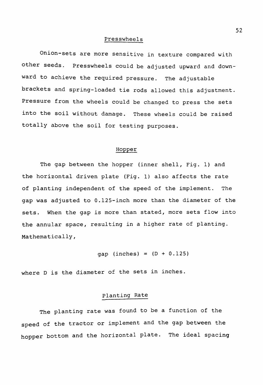
Presswheels
Onion-sets are more sensitive in texture compared with
other seeds. Presswheels could be adjusted upward and down
ward to achieve the required pressure. The adjustable
brackets and spring-loaded tie rods allowed this adjustment.
Pressure from the wheels could be changed to press the sets
into the soil without damage. These wheels could be raised
totally above the soil for testing purposes.
Hopper
The gap between the hopper (inner shell. Fig. 1) and
the horizontal driven plate (Fig. 1) also affects the rate
of planting independent of the speed of the implement. The
gap was adjusted to 0.125-inch more than the diameter of the
sets. When the gap is more than stated, more sets flow into
the annular space, resulting in a higher rate of planting.
Mathematically,
gap (inches) = (D + 0.125)
where D is the diameter of the sets in inches.
Planting Rate
The planting rate was found to be a function of the
speed of the tractor or implement and the gap between the
hopper bottom and the horizontal plate. The ideal spacing

53
between the sets is 2 to 2.5 inches. An average of five
to six sets per foot is an acceptable rate for 0.5 to 0.75-
inch sets. The horizontal plate surface was very smooth
and was not able to move the onion-sets due to less fric
tion. This was overcome by gluing 180-grit emory cloth on
contact surface, which increased the frictional force; the
flow of onion-sets was found to be satisfactory. During
the preliminary runs, the speed of the horizontal plate
was modified by changing to different drive sprockets.
Initially, a 12-tooth, 4.5-inch mean diameter sprocket was
utilized. The resulting planting rate was 20 to 24 sets
per foot, which was too high and the sets were touching
each other without any gap between them. A 10-tooth, 3-
inch mean diameter sprocket was used next. The planting
rate was reduced to 15 to 20 sets per foot, which was also
not optimum. Finally, a 6-tooth, 2.5-inch mean diameter
drive sprocket was attached and the planting rate was 6
to 7 sets per foot. This was very close to that recom
mended for 0.5 to 0.75-inch diameter sets. The gap be
tween the hopper bottom and the horizontal plate was set
at 0.625 inches as the sets used were no larger than 0.5-
inch diameter in these preliminary runs.
The rate of planting for the newly developed planter
was found to be directly proportional to the gap, forward
speed of the implement, and the ratio of number of teeth on
drive sprocket to the number of teeth on the driver.

54
A constant planting rate could be maintained by increasing
the speed and the gap. In two test runs, the speed was in
creased to 4 mph and the planting rate was found to be 6 to
7 sets per foot.
Performance of the Planter
The following data were collected for a 100-foot length
of row using the planter.
Tests 1 & 2: . Time required to travel 100 feet
= 36 seconds
The forward speed = (100 ft/36 sec) x
(1 mile/5280 ft) x (3600 sec/hr)
=1.89 mph
Tests 3 & 4: . Time required to travel 100 feet
= 17 seconds
The forward speed = (100 ft/17 sec) x
(1 mile/5280 ft) (3600 sec/hr)
= 4 mph.
Performance Calculations
Considering one implement with 2 rows.
Ef = (T^ X 100)/(Tg - "h "" " a

Where, ^^
Ef = Field efficiency
T^ = Theoretical time per acre
Tg = Effective operating time
= T^ (100/k) = T (100/100) = T o o o
Since,
K = Percentage of implement with
actually used = 100%
T, = Time lost per acre due to
interruptions that are not
proportional to area (minor
adjustment and repair)
= 15 minutes = 900 seconds
T = Time lost per acre due to a ^
interruptions that are
proportional to the area
(filling the bulbs in hopper)
= 15 seconds per fill up
T = Theoretical time per acre at o
1.8 9 mph
One acre = 208.7 ft x 208.7 ft = 43,560 ft^
Bed width = 40 inches = 3.33 ft
Number of Beds = 208.7 ft/3.33 ft = 62.67 beds
Bed length = 208.7 ft
T = 62.67 beds x 208.7 ft row x 36 sec)/
100 ft = 4,708 seconds.

56 To determine the number of fill ups required per acre, the
following calculations were made:
Hopper capacity = H.C. = (nD^h)/4
where
D = diameter = 12 inches
h = height = 20 inches
Therefore,
H.C. = n(12)^ (20)/(4) = 2261.95 in^ or
2261.95 in^/2150 in" per bushel
= 1.05 bushels.
One bushel contains 19,065 sets of 1/2-inch size:
1.05 bushel = 1.05 x 19,065 = 20,018.
Each full hopper contains approximately 20,000 sets. The
distance traveled from 20,000 sets at 6 sets per foot and
2 rows per bed:
= (20,000)/(6 X 2) = 1666.6 ft
Number of fill ups per acre = (62.67 beds/acre x 208.7 ft/bed)/
1666.6 ft = 7.8 fill ups/acre
Therefore,
T = 1 5 sec/fill up x 7.8 fill ups/acre a
= 117 seconds/acre
Ef = (4708 X 100)/(4708 + 900 + 117)
= 82.23%

57 Effective Field Capacity:
C = (S X W X Ef)/ (8.25 X 100)
where
Ef = Field efficiency, in percent
S = Speed in mph
W = Rated width of the implement
in feet
If two such implements were used with one tractor with
12-inch row width and 40-inch bed width, the total imple
ment width would be 2 x 40 inches/12 inches/foot = 6.66 ft,
and the effective field capacity would be:
C = (S)(W) (EF)/(8.25)(100)
= (1.89 x 6.66 ft X 82.23)/(8.25 x 100)
=1.25 acres/hour.
If four such implements were used with one tractor with 12-
inch row widths and 40-inch bed widths, the total implement
width would be 4 x 40 inches/12 inches/foot = 13.33 ft and
the effective field capacity would be:
C = (S) (W) (Ef)/(8.25) (100)
= (1.89 X 13.33 ft X 82.23)/(8.25 x 100)
= 2.51 acres/hour.
If six such implements were used, the effective field capacity
would be 3.75 acres/hour at 1.89 mph.
58
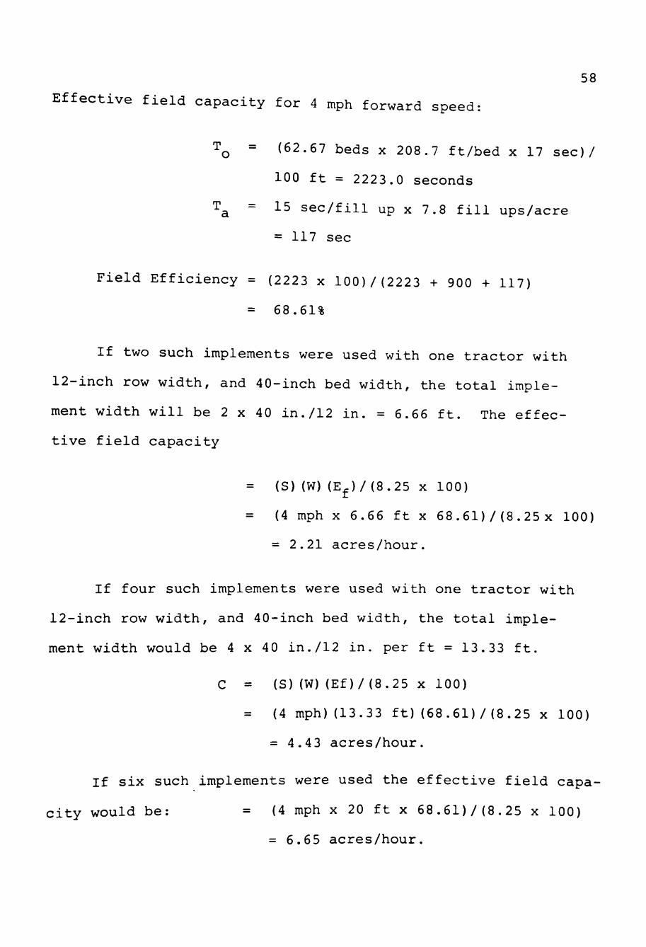
Effective field capacity for 4 mph forward speed:
TQ = (62.67 beds x 208.7 ft/bed x 17 sec)/
100 ft = 2223.0 seconds
T^ = 15 sec/fill up X 7.8 fill ups/acre
= 117 sec
Field Efficiency = (2223 x 100)/(2223 + 900 + 117)
= 68.61%
If two such implements were used with one tractor with
12-inch row width, and 40-inch bed width, the total imple
ment width will be 2 X 40 in./12 in. = 6.66 ft. The effec
tive field capacity
= (S)(W)(E^)/(8.25 X 100)
(4 mph X 6.66 ft x 68.61)/ (8.25x 100)
= 2.21 acres/hour.
If four such implements were used with one tractor with
12-inch row width, and 40-inch bed width, the total imple
ment width would be 4 x 40 in./12 in. per ft = 13.33 ft.
C = (S)(W)(Ef)/(8.25 X 100)
= (4 mph) (13.33 ft) (68.61)/ (8.25 x 100)
= 4.43 acres/hour.
If six such implements were used the effective field capa
city would be: = (4 mph x 20 ft x 68.61)/(8.25 x 100)
= 6.65 acres/hour.

CHAPTER VII
DATA ANALYSIS
The following data were observed while testing the
implement for the planting of two different sizes of onion-
sets .
Test Data Test No. 1 (Table I)
Mean diameter of the drive sprocket = 2.2 5 inches
Number of teeth on drive sprocket = 6
Speed of the tractor = 1.8 9 mph
Size of the sets used = 0.5 inch
Gap between hopper and horizontal
plate = 0.625 inch
Row length = 50 feet
Test No. 2 (Table II)
Mean diameter of the drive sprocket =2.25 inches
Number of teeth on drive sprocket = 6
Speed of the tractor =1.89 mph
Size of the sets used =0.75 inch
Gap between hopper bottom
and horizontal plate 5 =0.875 inch
ROW length = 50 feet
59
60
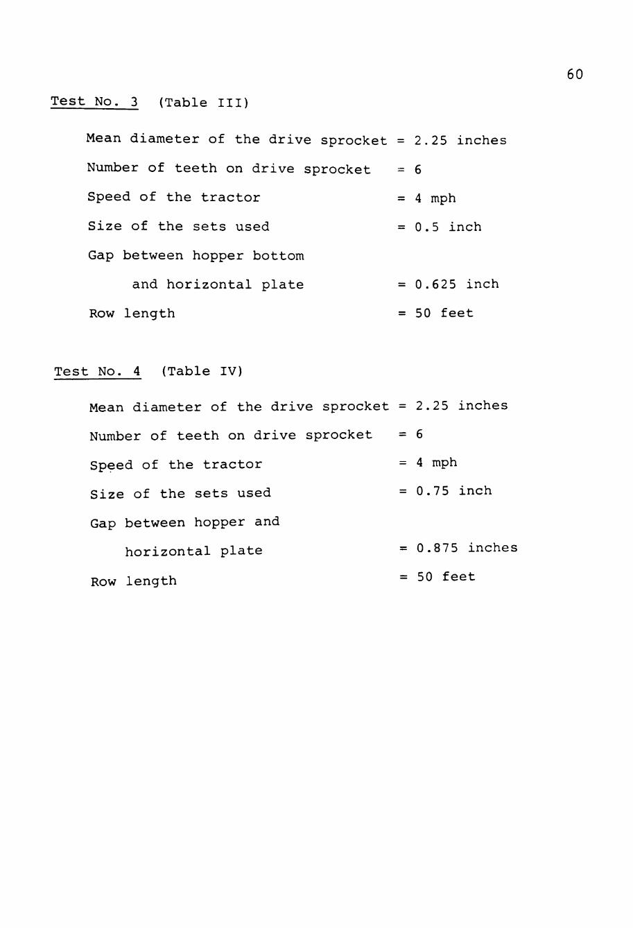
Test No. 3 (Table III)
Mean diameter of the drive sprocket =2.25 inches
Number of teeth on drive sprocket = 6
Speed of the tractor = 4 mph
Size of the sets used =0.5 inch
Gap between hopper bottom
and horizontal plate = 0.625 inch
Row length = 50 feet
Test No. 4 (Table IV)
Mean diameter of the drive sprocket =2.25 inches
Number of teeth on drive sprocket = 6
Speed of the tractor = 4 mph
Size of the sets used =0.75 inch
Gap between hopper and
horizontal plate = 0.875 inches
Row length = 50 feet

61
TABLE I
NUMBER OF SETS PER FOOT
Row Side Row Side Row Side Foot Foot Foot No. Left Right No. Left Right No. Left Right
1
2
3
4
5
6
7
8
9
10
11
12
13
14
15
16
17
7
6
6
6
5
5
5
6
5
5
6
6
5
5
5
7
6
6
5
6
5
5
6
7
4
6
5
4
6
5
6
6
8
5
18
19
20
21
22
23
24
25
26
27
28
29
30
31
32
33
34
8
6
6
7
6
7
7
6
6
5
6
6
6
7
5
6
5
5
5
6
6
6
6
7
7
5
5
6
5
4
6
6
6
6
35
36
37
38
39
40
41
42
43
44
45
46
47
48
49
50
5
5
6
6
7
6
6
7
6
6
4
6
5
5
4
6
6
4
6
6
6
6
6
5
5
6
6
5
5
6
5
4

62
11
TABLE II
NUMBER OF SETS PER FOOT
Row Side Row Side Row Side Foot Foot Foot No. Left Right No. Left Right No- Left Right
1 6 6 18 5 5 35 6 5
2 5 6 19 5 6 36 6 6
3 5 5 20 5 7 37 5 6
4 6 4 21 6 4 38 5 5
5 4 5 22 6 6 39 6 5
6 6 5 23 7 4 40 5 4
7 5 6 24 0 5 41 6 7
8 6 6 25 4 5 42 6 3
9 5 5 26 6 5 43 6 5
10 6 7 27 5 5 44 5 5
6 3 28 4 7 45
12 5 5 29 5 6 46
13 6 5 30 6 5 47
14 6 6 31 5 5 48
32 6 6 49
33 6 5 50
17 5 5 34 6 5
15 6 7
16 6 4

63
TABLE III
NUMBER OF SETS PER FOOT
Row Side Row Side Row Side Foot Foot Foot No. Left Right No. Left Right No. Left Right
1
2
3
4
5
6
7
8
9
10
11
12
13
14
15
16
17
6
6
5
5
6
5
6
7
5
7
8
6
6
5
6
5
6
6
5
7
5
5
5
6
5
4
5
6
7
5
5
5
6
6
18
19
20
21
22
23
24
25
26
27
28
29
30
31
32
33
34
5
5
5
4
6
4
7
7
6
0
0
1
6
5
6
6
5
6
6
5
6
5
5
6
6
6
5
0
6
5
6
4
5
6
35
36
37
38
39
40
41
42
43
44
45
46
47
48
49
50
5
6
6
5
5
6
7
5
5
5
6
6
7
5
5
6
5
6
5
6
5
6
4
7
5
6
6
7
5
5
5
6

64
TABLE IV
NUMBER OF SETS PER FOOT
Row Side Row Side Row Side Foot Foot Foot No. Left Right No. Left Right No. Left Right
18 5 6 35 5 5
19 6 5 36 6 6
20 5 5 37 5 6
21 5 6 38 6 5
22 5 5 39 5 5
23 6 6 40 6 7
7 7 4 24 6 5 41
8 6 5 25 5 4 42
0 c c, 26 4 6 43
10
11
12
13
14
15
16
17
6
5
4
4
0
5
5
6
6
6
6
4
3
6
5
6
27
28
29
30
31
32
33
34
4
6
6
6
4
1
1
6
4
6
7
5
0
2
2
6
44
45
46
47
48
49
50
6
6
6
6
5
5
5
5
6
7
6
5
5
5

65
Data collected from experimental runs of the planter
revealed the capability of planting onion-sets almost to the
optimum spacing of 5 to 6 sets per foot. However, at cer
tain places, the spacings were found either more or less
than those required. The reason may be because of the un-
evenness of the soil surface, sudden changes in the forward
speed of the implement or the presence of clods and crop
residue in the soil. Control of depth in opening the fur
row was found to be adequate. Covering the sets with soil
was also tested in a separate test and it was found that the
onion-sets were completely covered by the soil.
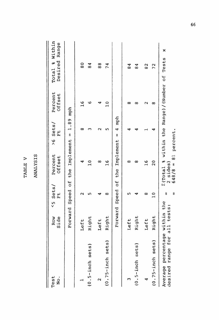
Analysis
The following information furnishes the onion-set
spacing offset between the rows and the overall performance
of the planter. Table V indicates that the percentage off
set in spacing the onion-sets in the rows was irrespective
of the forward speed of the implement, set size and row side.
The data was collected from preliminary tests using
the onion-set planter. Four runs of 50 foot each were evalu
ated. Two forward speeds, 1.8 9 mph and 4.0 mph, and two set
sizes, 0.5-inch diameter and 0.75-inch diameter, were used.
After each run the number of sets deposited in each foot of
the 50 foot row were counted and recorded. The planter had
two drop tubes and these were designated as left side and
66
<
H
•H x: - p • H
03
O
(U
c: fd «
(U 5-1
• H CO 0) Q
-P
0)
u 0) CM
- P (D W
VM
O
CO -p (U
cn VD A
Per
cen
t
-P !J4
Off
set
CO -p 0) CO
IT) V
^ 0 «
-p CM
0) T3 •H CO
4-> • CO O CU 2
E H
x: a. e
CO
0)
e (U
a
0)
-p
O
Q) CU
CO
OJ 15 5-1 O
O ' ^ 00 00
VD VD
00 ro
^ o
CM LD
00 00
CM i n
00 VD
00
+J ^-^ Q) i J
4-1 s: CP
•H OJ
4-> y-l 0) H^
-p ^ tT>
•H OJ
_» CO 4J Q) CO
x: u c; •H 1
in
CO 4J (U CO
x: 0
c •H 1
in r-
rsi
a e
-p c e 0)
e H
Q) x: -p o
O (U
CO
Ti 5H
O
00 00
00 00
00 CO
in
CO r-«
(N 00
VD O M (N
00
-p 4-1 0) y^
m
-P
x: en •H Oi
. ^ i i ^
CO 4-> dJ CO
x: u c •H 1
in •
o "—'
4J U-i
<u ^
^
•p
s: tp
•H
a
CO 4-> 0) CO
s: u c •H 1
in t^
• o -
Q) x: " •P CO
-p C CO
•H Q)
x: -p +j •H ,H
age
w o
r al
-p 4-1
c (1) (U U CP 5-1 C a (T3 a u 0) TJ
03 M ^ -H Q) CO > (U < ^
CO 4J CO
(U E H
4-1 O
5-1 0)
XI e p 2
0)
C
Ci
0 x: -p
c •H x: -p •H 5
-P C 0)
u 5-1
a 00
0 ^ — v
CO II rH 0) (d 'O 00 +J -H • ^ O to 00 EH ^ ^^ (N VD
II II

67
right side for clarification purposes. This then provided
rows, 50-foot in length, with 2 drills per row (left and
right side). Each of these provided a variation in plan
ting speed and set size. The tests were then performed to
determine the resulting variations from the desired spacing
of 5 to 6 sets per foot.
It is noted that 20 percent of the test row in Test
4, right side, had less than 5 sets placed in them. The
percentages for all other tests and sides decreased down to
4 percent of the 50-foot row with less than 5 sets. On the
other side of the spectrum, 16 percent of the rows in Test
1, left side, had more than 6 sets in them. Only 2 percent
of the left side. Test 4, had more than 6 sets. As can be
seen, the average total percent of test row having the
desired 5 to 6 sets per foot was 81 percent. This is an
acceptable value for the preliminary tests that were run.
Statistical analysis were not accomplished as these were
preliminary tests and insufficient data were collected from
which to draw inferences.
CHAPTER VIII
SUMMARY AND CONCLUSIONS
Onion production is enhanced when onions are grown
from sets because of earlier maturity and higher yields
as compared to seeds or transplants. The manual labor
associated with planting can also be reduced drastically
by mechanical planting. Considerable labor savings can
be achieved using this onion-set planter. One man with
one, two-row planter could cover 8.75 acreas in a 7-hour
work day and with 4 such planters, that one man could plant
35 acres per day. This compares with only one acre planted
by approximately ten hand laborers per day.
Other advantages of mechanically planting onion-sets,
as compared with hand transplanting, are as follows. Onion-
sets can be planted earlier, as it is not necessary to delay
planting while transplants attain proper planting size. The
task is less tedious with a machine and the operation can
be done at a lower cost. The problems and expense of grow
ing transplants are avoided. Onions produced from sets are
usually larger and the crop matures 3 to 4 weeks earlier
than when grown directly from seed. The onion-set planter
would enable planting to be done much more rapidly, this
is a critical factor when bad weather threatens.
68

69
The best size of onion-sets for planting is between
0.5 and 0.75-inch in diameter. Sets that are placed at
2.25 inches apart in a row and with 12 to 14 inches between
rows, all one one 40-inch seedbed, will give maximum yield.
This gives a desired planting rate of from 5 to 6 sets per
foot of row. In preliminary testing the planter gave an
average 81 percent of desired sets per foot in a 50-foot
test row length.
In the past, hand-planted sets, because of their
uniform spacing and position placing, out-yielded machine-
planted sets. In most instances, however, the reduced
labor by the use of machine planters more than offset the
reduction in yield and therefore provided lower costs of
production.
The performance of this newly developed planter in
proper placement of onion-sets was found to be directly
proportional to the gap between the hopper bottom and the
horizontal plate, and the ratio of number of teeth on the
drive sprocket to the number of teeth on the driven sprocket.
The developed planter, however, was not able to place the
onion-sets consistently in a vertical orientation. This
could possibly be a problem area if yield is reduced below
some economic threshold.
In conclusion, this research has revealed valuable
information pertaining to the mechanical planting of onion-
sets. It is suggested that further research and development

70
be directed toward:
1. Onion-set vertical orientation in the furrow
2. Covering of onion-sets for optimum growth
3. Labor savings of mechanical versus hand
planting
4. Yield of mechanical versus hand planting
5. Planting ungraded sets
6. Safety aspects of mechanical planting
7. Cost analysis of mechanical planting.

72
Splittstoesser, W. E. Vegetable Growing Handbook. AVI Publishing Company, Inc.: Westport, Connecticut, 1979, p 224.
Thuerman, J. H. , and Paul, E. A. "Recent Agricultural Chain Developments." Agricultural Engineer, Sep 1956, 37: 613-617.
Schacht, Otto B. Assistant Professor, Department of Agricultural Engineering and Technology, Texas Tech University, Lubbock, Texas. Interviews, 1981.
Shoemaker, James Sheldon. Vegetable Growing. John Wiley & Sons, Inc.: New York, N.Y., 1947, pp 191-194.
Vandermark, J. S. "Onions are Finicky as to Growing; Curing and Garlic May Not be Joy Either." The Yearbook of Agriculture, 1977, pp 152-156.
Walker, J. C. "Onion-Set Production." Farmer's Bulletin No. 1955. U.S. Department of Agriculture, May 1944, (revised Oct 1946), p 1.
Ware, G- W., and McCollum, J. P. Producing Vegetable Crops. The Interstate Printers & Publishers, Inc.: Danville, 111. , 1968.
Ware, George W. , and McCollum, J. P. Raising Vegetables. The Interstate Printers & Publishers, Inc.: Danville, 111., June 1959, pp 275-276.