development of advanced surface enhancement technology
TRANSCRIPT

Development of Advanced Surface Enhancement Technology
for Decreasing Wear and Corrosion of Equipment Used for Mineral Processing
FINAL REPORT
(7/21/2003 – 9/20/2007)
Prepared by
Daniel Tao, R. Honaker, and B.K. Parekh Department of Mining Engineering, University of Kentucky
234E, MMRB, Lexington, KY 40506-0107
AND
Craig A. Blue and Narendra B. Dahotre Oak Ridge National Laboratory
P.O. Box 2008 MS6083 Oak Ridge, TN 37831-6083
Prepared for
U.S. DEPARTMENT OF ENERGY
Mining Industry of the Future ProgramContract No. DE-FC26-03NT41787
December, 2007

DISCLAIMER
This report was prepared as an account of work sponsored by an agency of the United States Government. Neither the United States Government nor any agency thereof, nor any of their employees, makes any warranty, express or implied, or assumes any legal liability or responsibility for the accuracy, completeness, or usefulness of any information, apparatus, product, or process disclosed, or represents that its use would not infringe privately owned rights. Reference herein to any specific commercial product, process, or service by trade name, trademark, manufacturer, or otherwise does not necessarily constitute or imply its endorsement, recommendation, or favoring by the United States Government or any agency thereof. The views and opinions of authors expressed herein do not necessarily state or reflect those of the United States Government or any agency thereof.
I

ACKNOWLEDGEMENTS
This project is sponsored by the Department of Energy (DOE) under contract number DE-FC26-03NT41787 which is managed by Mr. Morgan Mosser. The industrial partners and government agencies involved in this project include AMVEST Mineral Service, Inc., Carbontronics Fuel Management, LLC., Massey Energy, CONSOL, Energy Industries of Ohio, Florida Rock Industries, Inc., Innovative Screen Technology, James River Coal Service. Co., Jeffery Chain Corp., Kentucky Coal Association, Kurtz Bros., Inc., Ohio Coal Development Office, and Phelps Dodge Mining Company. Their support to the project is greatly appreciated. The authors are also greatly indebted to the Big Creek Processing Plant of Massey Energy for their assistance in on-site testing.
II

ABSTRACT
Equipment wear is a major concern in the mineral processing industry, which dramatically increases the maintenance cost and adversely affects plant operation efficiency. In this research, novel surface treatment technologies, High Density Infrared (HDI) and Laser Surface Engineering (LSE) surface coating processes were developed for the surface enhancement of selected mineral and coal processing equipment. Microstructural and mechanical properties of the coated specimens were characterized. Laboratory-simulated wear tests were conducted to evaluate the tribological performance of the coated components. Test results indicate that the wear resistance of ASTM A36 (raw coal screen section) and can be significantly increased by applying HDI and LSE coating processes. Field testing has been performed using a LSE-treated screen panel and it showed a significant improvement of the service life.
III

TABLE OF CONTENTS
EXECUTIVE SUMMARY ................................................................................................ 1
INTRODUCTION .............................................................................................................. 2
Definition of Wear .......................................................................................................... 4
Types of Wear................................................................................................................. 4
WEAR IN MINERAL PROCESSING............................................................................... 4
SURFACE TREATMENT TECHNOLOGIES.................................................................. 9
Current Wear Protection Techniques Used In Mining Industry ..................................... 9
Ceramic Lining ........................................................................................................... 9 Surface coating.......................................................................................................... 10 CVD .......................................................................................................................... 10 PVD........................................................................................................................... 11 Thermal Spraying...................................................................................................... 11
High-Density Infrared (HDI) Surface Coating ............................................................. 12
Laser Surface Engineering (LSE) ................................................................................. 13
EXPERIMENTAL............................................................................................................ 16
Materials ....................................................................................................................... 16
Coating Preparation Using HDI.................................................................................... 17
Coating Preparation Using LSE.................................................................................... 18
Sample Characterization ............................................................................................... 20
On-site Testing.............................................................................................................. 24
RESULTS AND DISCUSSION ....................................................................................... 26
Microstructure of HDI-treated Samples........................................................................ 26
Microstructure of LSE-treated Samples........................................................................ 35
IV

Microhardness............................................................................................................... 43
Lab Wear Testing.......................................................................................................... 46
On-site Testing.............................................................................................................. 50
PROJECTED ENERGY BENEFITS ............................................................................... 56
CONCLUSIONS............................................................................................................... 58
REFERENCES ................................................................................................................. 60
V

LIST OF FIGURES
Figure 1 A failed screen panel due to wear......................................................................... 6
Figure 2 A typical dense medium vessel ........................................................................... 6
Figure 3. Schematic of a dewatering centrifuge ................................................................. 7
Figure 4. Plasma arc lamp................................................................................................. 12
Figure 5. The wavelengths of different lasers in the electromagnetic spectrum .............. 14
Figure 6. Schematic of the LSE process ........................................................................... 15
Figure 7 LSE facilities developed in this project.............................................................. 19
Figure 8. Allied TechCut10™ Abrasive Cut-Off Saw ..................................................... 21
Figure 9. Hitachi S-3200 SEM.......................................................................................... 22
Figure 10. Microindentation tester.................................................................................... 23
Figure 11. Block-on-ring tribometer................................................................................. 23
Figure 12. On-site test of coated screen panel .................................................................. 24
Figure 13. Coated screen panel for on-site testing............................................................ 25
Figure 14. Schematic of a test raw coal screen panel ...................................................... 25
Figure 15. Micrograph of the coated sample .................................................................... 26
Figure 16. OM images for Sample A1, Sample A2 and Sample A3 ................................ 27
Figure 17. OM images for Sample B1, Sample B2 and Sample B3................................. 28
Figure 18. OM images of Sample Y1, Y2 and Y3........................................................... 29
Figure 19. SEM images for Sample A1, Sample A2 and Sample A3 .............................. 31
Figure 20. SEM images for Sample B1, Sample B2 and Sample B3 ............................... 32
Figure 21. SEM images of Sample Y1, Y2 and Y3.......................................................... 33
Figure 22.The EDS result of AISI 4140 steel ................................................................... 34
Figure 23. AISI 4140 coupon with (Ni-10P)-50TiB2 coating.......................................... 36
Figure 24. Screen section with (Ni-10P)-50TiC coating .................................................. 36
Figure 25. OM image of Sample S3 ................................................................................. 37
Figure 26. Microstructure evolution of the coated sample ............................................... 38
Figure 27. SEM image of Sample C1 ............................................................................... 38
Figure 28. SEM image of Sample C3 ............................................................................... 39
VI
Figure 29. SEM image of Sample S3 (Overview) ............................................................ 39
Figure 30. SEM image of Sample S3 (Interfacial area).................................................... 40
Figure 31. EDS spectrum of Sample C1 (Near coating surface) ...................................... 41
Figure 32. EDS spectrum of Sample C1 (Near interface zone) ........................................ 41
Figure 33. EDS spectrum of Sample S3 (Near coating surface)....................................... 42
Figure 34. EDS spectrum of Sample S3 (Near interface zone) ........................................ 43
Figure 35. Microhardness profile of HDI samples (A1-A3)............................................. 44
Figure 36. Microhardness profile of HDI samples (B1-B3) ............................................. 45
Figure 37. Microhardness profile of Sample S3 ............................................................... 45
Figure 38. Image of microindentions (Sample S3)........................................................... 46
Figure 39. Block-on-disk wear test results of HDI samples A1, A2 and A3.................... 47
Figure 40. Block-on-disk wear test results of HDI sample (B1, B2 and B3) ................... 48
Figure 41. Block-on-ring test results of Sample C1-C4 ................................................... 48
Figure 42. Block-on-ring test results of Sample S1-S4 .................................................... 49
Figure 43. Wear rates of the test panels ............................................................................ 51
Figure 44. Test panel (Left:before test; Right: after test) ................................................. 52
Figure 45. Slot area change of Row 2............................................................................... 53
Figure 46. Slot area change of Row 10............................................................................. 53
Figure 47. Slot area change of Row 20............................................................................. 54
Figure 48. Slot area change of Row 30............................................................................. 54
VII

LIST OF TABLES
Table 1. Chemical compositions of AISI 4140 steel (in wt.%) ........................................ 16
Table 2. Chemical composition of ASTM A36 steel (in wt. %)....................................... 16
Table 3. HDI process parameters for Sample A1-A3 and B1-B3..................................... 18
Table 4. HDI process parameters for Sample Y1, Y2 and Y3.......................................... 18
Table 5. Coating processing conditions ............................................................................ 20
Table 6. EDS results for WC rich cluster ......................................................................... 34
Table 7. EDS results for the Matrix of WC coatings........................................................ 35
Table 8. EDS results for amorphous coatings................................................................... 35
Table 9. Three test panels ................................................................................................. 50
Table 10. On-site testing of three coated panels ............................................................... 51
VIII

EXECUTIVE SUMMARY
This project was aimed at developing advanced surface enhancement technology for decreasing the wear and corrosion rate of mineral processing equipment by an order of magnitude. The proposed process is expected to be easily adaptable to automation and less expensive than currently used methods. Such performance improvement will result in energy savings of 1.58×10¹⁴ Btu/year. Significant efforts have been directed toward reducing wear of cyclones, pumps, heavy medium vessels, etc. used in mineral processing during the last two decades or so. Major progress has been achieved through the use of ceramic linings that have considerably increased the lifetime of hydrocyclones. However, little has been done to reduce the wear of screens, chains for conveyors, and piping where ceramic lining is impractical. For example, screen aperture increases as material wears, resulting in inconsistent aperture sizes and lower screening efficiency. This creates non-ideal feed to downstream operations, reducing their efficiencies. The wear of pipes, particularly the joint elbows, is another major concern of plant operators. The combination of corrosion and wear severely impacts the life span of chains, especially pin, bushings, and side plates. For horizontal conveyor systems, current materials used for chains include chrome-plated pins in an effort to minimize the combined wear/corrosion issues. However, stress-corrosion issues of chain components are continual problems. For inclined systems, corrosion issues are more limited; however, significant wear issues remain. Frequent replacements of screens, conveyors, and pipes increase equipment downtime and maintenance cost and reduce process efficiency. The development of advanced surface enhancement technology is of great interest for the mineral processing and coal preparation industry.
This project has been focused on the following aspects:
1. Investigating major wear issues involved in mineral processing and coal preparation processes.
2. Developing two advanced surface treatment technologies, High Density Infrared (HDI) and Laser Surface Engineering (LSE) surface coating processes, to produce surface coatings with enhanced wear resistance.
3. Designing and evaluating wear performances of different surface coatings in laboratory and applying viable coatings on selected mineral processing equipment and components.
4. Performing field testing on coated mineral processing equipment to determine the wear performance of LSE-coated mineral processing equipment.
5. Evaluating energy savings generated by applying the surface coating technologies into coal and mineral processing industry.
1

INTRODUCTION
Wear is referred to as the damage to the solid surface. In most cases, material is removed from the solid surface progressively, due to the relative motions between the contacting parts (ASTM, 2003). The components may need to be replaced even if a small amount of material has been removed in most cases, e.g. piston seal used to seal the combustion compartment. Other components tolerate some materials loss until it fails to perform functionally. The main mechanisms of relative motion include applied loads and relative motion which can cause adhesion, abrasion or fatigue (Bull, 1997).
There are three major types of wear related to the research in this project including:
1. Abrasive wear- wear due to hard particles or hard protuberances forced against and moving along a solid surface. Sometimes it happens between two smooth surfaces due to hard debris or contaminant particles trapped in. In the process hard particles penetrate the solid surface and plough a series of grooves, from surface scratch to deep gouge. The material is removed from the solid surface. Abrasive wear occurs in many different operations, such as mining, mineral processing, aggregate industry and other heavy load industries dealing with hard materials. The annual cost of replacing those worn parts caused by abrasive wear is a major part of maintenance expenses in these industries.
2. Impact wear – wear due to collisions between two solid bodies where some component of the motion is perpendicular to the tangential plane of contact;
3. Sliding wear – wear due to the relative motion in the tangential plane of contact between two solid bodies.
Material wear performances are usually vital to the performance of industrial equipment in terms of efficiency and life cycle costs, which explains why considerable amount of effort has been devoted in developing surface treatment technology to improve material wear performance in almost every sector of industry.
When wear happens, it is important to identify which type of wear is happening. One way to identify the wear type is to study the appearance of the worn surface. The nature of the application can be another clue to knowing the wear type. How are the surfaces contacting with each other, low stress or high stress? Are there any hard granular materials between the surfaces? For example, erosion normally happens in the presence of high speed fluid with particles making contact with surface.
Once the main type of wear is identified, the appropriate wear resistant materials can be found, or the right surface enhancement, i.e. coating can also be applied. The suitable wear test is then conducted to inspect the wear performance of the new surface to satisfy the requirements of the application.
2

Minerals and coal are essential to every aspect of our lives. It is estimated that 46,000 pounds of new minerals including 7,500 pounds of coal must be provided annually for every person in the US to maintain their standard of living (Mining Journal Ltd., 1999). Mineral and coal are the essential parts of the economy as well. The process of extraction and concentration of economic minerals/coal contained in run-of-mine (ROM) ore is referred to as mineral/coal processing.
Wear has long been recognized to be one of the most common problems in the heavy-equipment industry of mineral processing due to their significant impacts on material wastage and maintenance costs (Dunn, 1985). During the last two decades or so, significant efforts have been directed toward reducing wear of comminution equipment (Iwasaki et al, 1987; Zheng et al 1997; Pitt et al, 1987), heavy media cyclones (Foster, 1996; Zughbi et al, 1991), pumps (Perez et al,. 1990), etc., used in mineral processing. Major progress has been achieved through the use of ceramic linings that have considerably increased the lifetime of hydrocyclones (Foster, 1996). Nevertheless, little has been done to reduce the wear of screening equipment, heavy medium vessels, and dewatering centrifuge, etc. The development of advanced surface enhancement technology is of great interest for the mineral processing and coal preparation industry.
Surface coating as a manner of equipment wear life enhancement has been well established in engineering applications and many coating techniques have been extensively studied (Dowson and Taylor, 1985). In this project the major wear issues involved in mineral processing and coal preparation processes were investigated. Two surface treatment technologies, High Density Infrared (HDI) and Laser Surface Engineering (LSE) surface coating processes, were developed to produce surface coatings for mineral processing equipment with enhanced wear resistance.
The HDI-based surface treatment process is a patented technology developed by the Oak Ridge National Laboratory (ORNL). It involves producing infrared heating with extremely high power densities of up to 3.5 kW/cm2 using a unique plasma arc lamp (PAL) system. Coating materials are fused by the PAL, yielding metallurgical bonding between coating and substrate.
The use of lasers in surface coating has emerged as a field of growing importance to materials science and engineering. Laser surface engineering is known as a non-equilibrium synthesis involving high heating and cooling rates (103-108 K/s), which leads to the development of a wide variety of microstructures with novel properties that can not be achieved by any conventional processing technique (Mazumder, 1996).
Extensive laboratory and on-site tests were performed to identify the most viable coatings. It has been found that a more than ten-fold wear life improvement can be achieved on coated AISI 4140 steel samples in laboratory. On-site tests indicated that raw coal screen lifespan can be doubled through the application of coatings developed in this study. Potential energy savings generated by applying the particular surface coating technologies proposed in this project were calculated.
3

Definition of Wear
Wear is defined as the damage to a solid surface, which usually involves progressive loss of materials, due to relative motion between that surface and a contacting substance or substances. It manifests in the form of small separated particles (wear particles) and in changes to the material and shape of the tribologically stressed surface (ASTM, 2003)
Types of Wear
There are many forms of wear. The main types of wear are summarized as follows (ASTM, 2003):
Abrasive wear — wear due to hard particles or hard protuberances forced against and moving along a solid surface.
Corrosive wear — wear in which chemical or electrochemical reaction with the environment is significant.
Cutting wear — the erosive wear associated with the dissipation of kinetic energy of impact arising from the tangential component of the velocity of the impacting articles.
Deformation wear — the erosive wear of a material associated with the dissipation of kinetic energy of impact arising from the normal component of the velocity of the impacting particles. It is therefore the sole component of wear for particles impacting at a 90o angle of attack.
Fatigue wear — wear of a solid surface caused by fracture arising from material fatigue.
Fretting wear — wear arising as a result of fretting which is defined as the small amplitude oscillatory motion, usually tangential, between two solid surfaces in contact.
Impact wear — a process resulting on a continuing succession of impacts between (liquid or solid) particles and a solid surface.
Rolling wear — wear due to the relative motion between two non-conforming solid bodies whose surface velocities in the nominal contact location are identical in magnitude, direction and sense.
Sliding wear — wear due to the relative motion in the tangential plane of contact between two solid bodies.
WEAR IN MINERAL PROCESSING
Mineral processing is the science of separating valuable minerals from the gangue minerals out of ores to produce basic materials such as coal, quartz, salt, copper and gold
4

that are used in the industry and everyday life. Mineral processing usually includes several unit operations, including comminution, classification/screening, concentration/processing and post-treatment (e.g., product dewatering). The mineral processing industry deals with a very large tonnage of mineral ores and products. Equipment wear happens inevitably in every stage of the process, which increases the equipment maintenance costs and plant downtime and reduces the process efficiency of the plant. Wear is believed to be one of the most significant problems in the mineral processing industry. It is estimated that up to 40% operating costs of a mineral processing plant are caused by equipment maintenance (Laurila and Budge, 2000). The equipment wear problems that exist in each of the aforementioned processes are discussed as follows:
Comminution is referred to as the gradual reduction of a hard mineral to a fine powder by crushing or grinding for direct use or further processing. This includes liberation of a product, such as coal from non-coal material. It also includes primary crushing, where run-of-mine ore is reduced to a size small enough to feed a secondary crusher and rock is broken down to an adequate size for grinding. Mineral comminution, especially grinding, requires large energy costs and may account for more than half of hard rock processing energy costs (Wills, 1985). According to the mining annual review conducted by the Mining Journal (1999), approximately 29 billion kWh of electrical energy is consumed each year for size reduction. Therefore, wear issues associated with this energy intensive process of comminution have been extensively studied and many approaches, from optimizing the equipment design to the development of wear resistant materials, have been adopted during the past two decades (Durman, 1988; Norman, 1980). The wear issues regarding comminution equipment is beyond the scope of this research.
Screening is a critical unit process in mineral processing. Screen is the most commonly used device in the mineral processing industry to separate particles by size. Modern mineral processing would not be possible without efficient screening. In a coal processing plant, screening accomplishes sizing by passing coal of different sizes through a series of screens, each of a decreasing size. The individual screen discharges are then directed into different screen products for subsequent processing or sale. In processing industry, screens are also used for product dewatering, heavy media recovering, etc. (Leonard and Hardinge, 1991). During screening process, the aperture size increases as material wears, e.g. Figure 1, resulting in inconsistent aperture sizes and lower screening efficiency because more oversize particles may report to the underflow, which as a result creates non-ideal feed to the downstream processes.
Sieve bend is another high capacity screening device widely used for fine particle (150 μm ~ 3 mm) classification. Coal slurry is fed tangentially to the concave surface of a sieve bend, which provides a centrifugal force that presses the feed liquid layer against the screen surface. A shaving of liquid is formed due to the centrifugal force together with a retardation of the fluid velocity next to the screen (caused by frictional drag). Therefore, the particle classification is achieved when the shaved liquid enters the open slots and reports to the underflow stream. During fine particle classification, the bar
5

between two adjacent slots of a sieve bend becomes rounded due to wear. Most sieve bends are made of stainless steels, and the wear life of most surface screens is usually between 1,000 and 2,000 hours of operation. Frequent replacement results in high maintenance costs.
Figure 1 A failed screen panel due to wear
Figure 2 A typical dense medium vessel
Concentrating is the process of separating valuable minerals from their ores using the physical or physico-chemical property differences of different components. There are many mineral concentrating processes used in the coal and mineral processing industry. Dense medium separation process is the most widely used coal processing method, which accounts for 49% of the processing units used worldwide (Laurila, 1998). There are two types of dense medium separators in mineral processing, which are dense medium
6

cyclone and dense medium vessel, as shown in Figure 2. Since ceramic linings have been developed and commercially used in dense medium cyclones to protect their inner walls (Foster, 1996), the wear enhancement of dense medium cyclones will not be covered in this research. It should be noted that the wear issues concerning heavy medium vessels which accounts for 26.3% of the coal preparation units in the United States (Laurila, 1998) have not been well addressed. In a heavy medium vessel, a feed sink plate is usually used to direct the feed (raw coal and dense medium suspension) downward into the vessel so that particles do not raft across the width of the bath. Thus, the plate is subject to high wear as the feed slides down along the plate into the vessel.
Figure 3. Schematic of a dewatering centrifuge
The purpose of product dewatering is to control the post-processed product, e.g., clean coal, to an acceptable moisture level. Centrifuge is commonly used in the coal preparation and mineral processing industry for product dewatering. A typical perforate-basket centrifuge is schematically shown in Figure 3. Centrifuges achieve separation by means of the accelerated gravitational force achieved by a rapid rotation. The separation is similar in principle to that achieved in a gravity separation process. The driving force is higher because it is resulting from the rotation of the liquid, unlike gravity sedimentation, where the driving force is from the difference in density between the solid particles and the liquid. The centrifuge separation is achieved with a force 1000 to 20000 times of the gravity. The centrifuge screen is subjected to wear when particles are pressed against the screen surface due to the high centrifugal force generated by the fast rotation.
It should be mentioned that the literature survey conducted by the author indicated that the equipment wear issue in mineral processing has not been well addressed. In the past, research efforts have been mostly focused on the wear problems of the energy-intensive comminution equipment. Little work has been done on the study of wear enhancement of screening, heavy medium vessel and dewatering equipment. Although
7

the energy consumption of these devices is much lower than that of the comminution equipment, wear deteriorates the separation performances of these devices and, as a result, affects the overall plant process efficiency is affected.
During the last two decades, significant efforts have been made to reduce wear of cyclones, heavy medium vessel, pipe lines and pumps which are widely used in mineral processing. The goal has been realized by using the ceramic linings to coat the inner surface of the high wear equipment (Foster, 1996). The different shapes of ceramic linings are installed inside the vessels and cyclones, which are much harder and have stronger wear resistance. They can greatly increase the lifetime of mineral processing equipment (Nonnen et al., 1985).
However, research has not been effectively performed to reduce the wear of screens, chains for conveyors and pug mill paddles for coal mixing, which have to be replaced very often as a result of wear. Due to size and complex geometry of screen, it is not feasible to apply ceramic lining to the screen. As the screen wears, the screen openings will become wider and wider. During this process, the screen loses the consistency of aperture and reduces the screening efficiency. The increased screen openings also reduce the efficiency of downstream operations due to non-ideal feed to them. Furthermore, the replacement of screens will increase the plant shutdown time and reduce the overall plant efficiency. The development of advanced surface enhancement technology and its application to screens and other equipment to enhance their wear lives are strongly desired by the mining and mineral processing industry.
8

SURFACE TREATMENT TECHNOLOGIES
The use of best industry practices in the energy efficiency of machinery and equipment can lead to longer equipment life and significant energy savings for the mineral processing industry. The wear of mineral processing equipment can be minimized by using new improved constructions of working parts, special wear-resistant materials, or both. With most machines there exist a number of factors that the designer can control to minimize wear. The application of improved materials in mineral processing equipment manufacturing can reduce machinery wear, reduce repair and replacement costs, and extend machinery lifespan.
For screening equipment, a noticeable trend is the use of polyurethane as a substitute for the steel screen panels. Polyurethane is believed to have high wear resistance (Hill et al, 1997; Beck and Truss, 1998). Polyurethane screening panels have been successfully applied in the coal processing industry and have proven to be generally economical due to the long wear life and low maintenance requirements (Wolff, 1989). The noise pollution typical of wire screens and perforated plate is greatly reduced with the introduction of polyurethane screening. However, for coarse mineral and coal screening, steel screen panels are still the primary choice due to its higher capacity and lower cost. Wear problems relating to this kind of equipment have not been well addressed. In regards of sieve bends, recent improvements include the improved design and the introduction of polyurethane screen surfaces.
Transient performance is a problem that baffles all sieve bend operation. A new sieve bend presents a full-screen of sharp wires which normally remove acceptable amounts of the feed slurry. However, as the wires wear, the sieve performance eventually deteriorates to an unsatisfactory condition. After a period of service time, the wires at the feed end of a sieve bend are more worn than the wires at the discharge end. This happens because the slurry velocity is higher at the feed end of the screen than at the discharge end and this differential in slurry velocities from feed end to discharge end also abrades the wires at differential rates. The only approach to correct this problem is to turn the sieve screen, even though the wires at the discharge end of the screen are not fully worn in the correct direction and ready for turning. A VariSieve™ sieve bend has been introduced by Kerbs (Tucson, AZ). It is said to have an on-line adjustment system to enhance the wear life of screen performance. For the purpose of improved screen wear life, polyurethane screen surfaces have been applied in sieve bends by Derrick (Buffalo, NJ). The application of this device in fine coal dewatering and classification has not yet been reported.
Current Wear Protection Techniques Used In Mining Industry
Ceramic Lining
Ceramic lining was used to protect the mining and mineral processing equipment from wear two decades ago, which has been widely adopted for cyclones, heavy medium vessel, pipe lines and pumps. The different shapes of ceramic linings are installed inside
9

the vessels and the cyclones, which are much harder and have stronger wear resistant abilities. They can greatly increase the lifetime of the equipment (Nonnen et al., 1985).
Foster (1996) applied the ceramic linings to pipe line and cyclone in the industries like mineral processing, oil and gas and petrochemicals, which allow these high wear equipment to deal with millions of tons of aggressive materials without replacement.
Odawara (1985 and 1996) conducted the extensive research for the new technologies to process the ceramic lining for the pipe. The centrifugal-thermit process and self-propagating high-temperature synthesis (SHS) technology were investigated and showed improvement and successful applications.
Due to the size and geometry of mineral processing equipment, it is not feasible to apply ceramic lining onto the screen. Other wear equipment and components such as dense medium plates, chain conveyor and pug mill paddle are in great need for an effective coating technology to enhance their wear resistance.
Surface Coating
Steels are the most common materials of construction for the equipment used in coal/minerals mining and processing industry. Several reasons for using steels include: being the lowest cost material, readily manufacturable into complex shapes, and heat-treatable by several techniques to obtain a range of surface and bulk properties. Surface coating as a manner of equipment wear life enhancement has been well established in engineering applications and many coating techniques have been extensively studied (Dowson and Taylor, 1985). Today, coatings are widely used for many purposes including the surface enhancement of different steels. It is almost impossible to think of an item that does not have a coating of one type or another. Numerous coating techniques including chemical vapor deposition (CVD), physical vapor deposition (PVD) and thermal spraying, etc. have been widely used in the industry to synthesize different coatings on steels.
CVD
CVD process may be defined as the deposition of a solid on a heated surface from a chemical reaction in the vapor phase. During CVD process, a mixture of gases interacts with the surface of a substrate at a relatively high temperature, resulting the in the decomposition of some of the constituents of the gas mixture and the formation of a solid film of coating of a metal or a compound on the substrate. It belongs to the class of vapor-transfer processes which is atomistic in nature, i.e., the deposition species are atoms or molecules or a combination of both (Hugh, 1999).
CVD process has high throwing power. Deep recesses, holes and other difficult three-dimensional configurations can usually be coated with relative ease. And the deposition rate of CVD is high and thick coatings can be readily obtained. CVD
10

equipment does not normally require ultrahigh vacuum and generally can be adapted to many process variations.
One pronounced disadvantage of CVD is that it is most versatile at temperatures higher than 600 oC; many substrates, e.g., tool steels, are not thermally stable at these temperatures. Thus, the application of diamond CVD is limited to materials which will not soften at this temperature such as cemented carbides. The use of plasma-CVD partially offsets this problem. For example, Blum et al.(1999) reported the development of enhanced wear-resistant amorphous SiC coatings on steel substrates using plasma-enhanced CVD.
All CVD systems require a mechanism to treat the products of the chemical reactions. These products contain various reactive and potentially hazardous constituents, as well as particulate matter, which must be trapped and neutralized before the gases are exhausted to the atmosphere (Bhat, 2001). Therefore, environmental concern is another drawback of CVD process.
PVD
PVD process is defined as the creation of vapors in a vacuum from solid material sources and their subsequent condensation onto a substrate. Unlike the CVD process, the PVD process is a line-of-sight process conducted at lower temperatures (180 ~ 500 oC), and a physical bond is created between the coating and substrate rather than a chemical bond. Line of sight means that only those areas exposed to the plasma will be coated.
Low PVD processing temperatures mean that nearly all tool materials can be coated without concern of softening or distortion. There are three main methods for PVD deposition: arc evaporation, magnetron sputtering and electron beam evaporation. While subtle differences exist between these techniques, all contain three steps: ion emission from a source, vapor transport in a vacuum and condensation on the substrate surface.
PVD coating technology has been well established for cutting and forming tools, but for parts with complicated geometries, the development has not finished yet. Because of the numerous process parameters, coating techniques are of high complexity, and it is difficult to predict the outcome.
Thermal Spraying
Thermal spray coatings have been applied on a broad range of wear resistance surfaces. There are many types of thermal spray processes. According to the heat sources of each process, thermal spray processes are classified into two categories: combustion and electrical. Combustion includes low velocity flame spraying and high velocity flame spraying (HVOF), and electrical processes have wire arc spraying, plasma thermal spraying and cold spraying. But all the processes involve the deposition of very fine metallic or nonmetallic materials in a molten or semi-molten condition onto a substrate.
11

The feed materials are ejected by a gun, which heats the materials to molten state and then accelerates the molten materials by the compressed gas to the substrate. When the particles hit the substrate surface, lamellar or layered splat structures are formed due to the accelerated particles striking on the surface, spreading over and then solidifying on the substrate. A common character of all thermal spray coatings is their lamellar splat structure, which are the main reason for the formation of pores in the final coatings.
Although thermal spray coatings have achieved some success in the mining industry (Perrott, 1982, and Kembaiyan and Kenshavan, 1995), the splat structures can cause different levels of porosity and the amount of oxide inclusions in the final coating. Because the molten and semi-molten particles hit the cold substrate at a very high speed, after the coating solidified, there will be un-molten parts in the coating which are very easy to be worn out when they are exposed to the severe environment. Another shortcoming is that typically coatings are mechanically bonded to the substrate, which means the coating interlocks the substrate with the rough surface from blasting. Mechanical bonding provided very weak adhesion force between coating and substrate. In sight of the shortcomings of thermal spraying and the increasing requirements of high quality coatings, thermal spraying itself can not be a satisfactory surface enhancement method for the mining and mineral processing industry. The goal of this study was to develop a new coating technology to avoid the drawbacks of thermal spray coating to greatly improve the wear performance of equipment and components.
High-Density Infrared (HDI) Surface Coating
High-Density Infrared (HDI) process is a novel technology developed by the Oak Ridge National Laboratory (ORNL). This process involves producing infrared heating with extremely high power densities of up to 3.5 kW/cm2 using a unique plasma arc lamp (PAL) system.
Figure 4. Plasma arc lamp
12

The lamp, as shown in Figure 4, consists of a quartz tube of 3.175 cm in diameter and 10.16 cm, 20.32 cm or 38.1 cm in length. The lamp is sealed at the ends where the cathode and anode are located. Deionised water mixed with argon or nitrogen gas enters at the cathode side through high velocity jets impinging at a given angle. Due to the high velocity and pressure, the water is then impelled to the wall of the quartz tube and spirals down the length of the tube in a uniform film of 2-3 mm thick. This water film serves two purposes: to cool the quartz wall and to remove any tungsten particulates that may be expelled from the electrodes. The gas moves in a spiral fashion through the center of the tube, and a capacitative circuit initiates the plasma which has a temperature in excess of 10,000 K, is stable and produces a radiant spectrum of 0.2-0.4 μm. The plasma is absorbed by metal surfaces with high efficiency. The powder coatings of wear resistant materials are also highly absorbing, because the open areas act like black bodies. Figure 9 shows an actual plasma-infrared lamp used at ORNL.
Infrared heating is an inherently clean, noncontact heating method that provides rapid-response energy fluxes capable of heating rates in excess of 3000o C/s, rapid power-level changes, high cooling rates and a controllable temperature-gradient. Coating materials are fused by the PAL, yielding metallurgical bonding between coating and substrate. It was demonstrated that the method could fuse and metallurgically bond coatings and steel substrates without convective mixing, providing a new means for the rapid thermal processing of surface coatings (Engleman et al., 2002). It has been applied to the treatment of metals (Blue et al., 2000; Muralidharan et al., 2004). HDI surface treatment process has been successfully applied in the wear parts used for bulldozers manufactured by the Caterpillar Inc. More than 5-fold of wear enhancement has been achieved (Blue, 2002). Advantages of using a plasma radiant source to fuse coatings include:
Large area coverage (3.175 × 35 cm in a line focus and up to 10 × 20 cm in a uniform irradiance) No convective mixing of coating material with the base material Rapid cooling of coating material Minimal effects on base material No degradation of carbide reinforcements in coating No temperature limitation (can readily melt tungsten - melting point =
3410o C)
Laser Surface Engineering (LSE)
Steels are the most common materials of construction for the equipment used in coal/minerals mining and processing industry. Several reasons for using steels include: being the lowest cost material, readily manufacturable into complex shapes, and heat-treatable by several techniques to obtain a range of surface and bulk properties. Surface coating as a manner of equipment wear life enhancement has been well established in engineering applications and many coating techniques have been extensively studied
13

(Dowson and Taylor, 1985). Today, coatings are widely used for many purposes including the surface enhancement of different steels. Among the many surface treatment processes that are available today, lasers provide a unique tool for high quality surface modification. Many surface-related failures by mechanism involving wear, corrosion, erosion or high temperature oxidation can be minimized by laser surface modification (Mazumder, 1996; Steen, 1995). Surface modification using laser can take place in a variety of forms, depending on laser type and the materials to be treated.
Figure 5. The wavelengths of different lasers in the electromagnetic spectrum
There are three types of lasers that are of sufficient energy and robustness that are used for surface treatment (Folkes, J., 1997) which are Carbon Dioxide (CO2) Laser, Neodymium-doped Yttrium Aluminum Garnet, (Nd:YAG) Laser and Excimer Laser. Figure 5 shows the location of some of the lasers in the electromagnetic spectrum (Folkes, 1994).
The carbon dioxide laser can be pulsed or continuous wave and ranges in power from typically 0 to 10 kW. It has an output wavelength in the far infrared, in the region of 10.6 μm. This wavelength is relatively long so generally the surface modification occurs by heating effects. The energy density and interaction time between the laser and the substrate, as well as the ability of the surface to absorb this wavelength are the main factors that determine the resulting surface modification.
The Nd:YAG laser can be pulsed or continuous wave and ranges in power from 0 to 3 kW. This output wavelength is 1.06 μm which is shorter than the carbon dioxide laser but still in the infrared region. Thus, the surface modification occurs by heating effects, however coupling the laser radiation into the surface tends to be easier due to the shorter wavelength.
The Excimer laser is pulsed and ranges in energy from 0 to 600 J. There are several different excimer lasers depending on which gas is used inside the system to achieve the laser action. The output wavelength is in the ultra violet region (200 ~ 400 nm). These wavelengths are relatively short and generally the surface modification occurs by a combination of photon interaction and heating effects. Since the wavelength is short the surface interaction/coupling of the laser into the surface is paramount in understanding the process.
14

Figure 6. Schematic of the LSE process
Typical laser surface modification processes include (1) transformation hardening, (2) surface melting, (3) surface cladding, (4) surface alloying and (5) other techniques (surface smoothing, texturing, coating removal and micromachining, etc.). Due to the overlapping of the various laser surface modification processes, a new term “Laser Surface Engineering (LSE)” was proposed by Agarwal (1999) and therefore LSE was used in this proposal. A typical LSE process is schematically shown in Figure 6.
Laser surface engineering is known as a non-equilibrium synthesis involving high heating and cooling rates (103-108 K/s), which leads to the development of a wide variety of microstructures with novel properties that can not be achieved by any conventional processing technique (Mazumder, 1996). Other features of laser surface engineering include (Dahotre, 1998):
High coating thickness (up to 0.8 mm) Metallurgically bonded coating Non-equilibrium synthesis process leading to the development of novel phases Precise control of processing parameters Beam can be shaped for a variety of energy distributions High flux densities (>104 w/cm2) Laser beam transport to remote locations via fiber optics Allows for the processing of a wide variety of part configurations Amenable to automation
15
EXPERIMENTAL
Materials
The mineral processing industry requires materials having strength, toughness, wear and corrosion resistance. As in any heavy equipment industry, steel is the major material for equipment manufacturing in mineral processing industry. In this study, two commonly-used steels were selected as substrates in this research, which are AISI 4140 and ASTM A36, respectively. AISI 4140 is one of the chromium, molybdenum, manganese low alloy steels noted for high toughness, good tensile strength as well as high fatigue strength. It is widely used in fabrication of equipment used in the mineral processing industry. ASTM A36 is widely used for framing and general structural purposes to provide strength and stability. Also, the screen panels studied in this research are made of this steel. The chemical compositions of AISI 4140 and ASTM A36 are listed in Tables 1 and 2, respectively.
Table 1. Chemical compositions of AISI 4140 steel (in wt.%)
Element C Mn P S Si Mo Cr Fe
Weight,% 0.38 - 0.43
0.75 - 1.00
0.035 (max)
0.04 (max)
0.15 - 0.30
0.15 - 0.25
0.8 - 1.10 Bal.
Table 2. Chemical composition of ASTM A36 steel (in wt. %)
Element C P S Si Cu Fe
Weight, % 0.25 0.04 0.05 0.4 0.2 Bal.
High energy surface treatment processes using ultra-hard ceramic materials as coatings have been studied to develop wear resistant steels to meet the extreme requirements of wear, oxidation and corrosion resistance (Agarwal, 2000; Khedkar et al., 1997). Formation of metallurgically sound interface between the coating and the substrate is very critical for coating development. However, as the physical properties such as thermal expansion coefficient (CTE) between the ceramic and the steels usually are different, cracks usually develop at the ceramic/steel interface as well as within the coating during the rapid solidification and cooling progress (Agarwal et al., 2000). The use of binders in coating materials can promote the good adhesion between the coatings and the steel substrates. For example, iron has been revealed as an excellent binder for Ti-based coatings on steels (Raghunath et al., 1995). In this project, several kinds of binders were investigated for both HDI and LSE coating processes.
Composite coatings have gained great interest from researchers and the industry for the wear performance of coating. Tungsten carbide (WC) and iron-based amorphous
16

coatings are two main components. WC has high hardness, good strength and is stable with Ni-P base materials. It has been shown the successful application of WC coating with Ni-P base greatly increased coating wear resistance of HID-treated samples (Engleman et al., 2002). Iron-based amorphous materials, for example (Fe-15Cr-14Mo-2Y-15C-6B, wt%), have been reported to have high strength and good wear resistance as well (Pang, 2002). Therefore, these two types of materials were chosen as coating materials in this study. WC coating materials, 40(Ni-10P)-60WC, use 40 wt.% Ni-P (30 wt.% Ni + 10 wt.% P, ≈50 µm) as binder and WC powder (60 wt.%; ≈50 µm) as reinforced addition. Iron based amorphous materials Fe-15Cr-14Mo-2Y-15C-6B, wt% were investigated as another type of coating materials for the HDI process in this research.
Coating materials studied in LSE process included above-mentioned ceramic coatings and thermite coatings. The word “thermite” is usually used to describe exothermic reactions which involve reduction of metallic oxides with aluminum to form aluminum oxide and metals or alloys (Wang et al., 1993). WC has high hardness, good strength and is stable at high temperatures (Chong et al., 2001). Thermite+WC coating powders [(Fe3O4-34.4Al)-60WC, wt%) were used as coating precursor in the present investigation.
Coating Preparation Using HDI
The HDI process includes two passes through the plasma arc lamp. The first pass was run at a lower power. The purpose of first pass is to 1) preheat the substrate to enhance wetting, 2) decrease residual stress between substrate and the thermal sprayed coatings, and 3) decrease the possibility of introduction of thermal stress. The second pass adopted the higher power to melt and fuse the coating precursor. All of the HDI process passes were performed at a traverse speed of 10 mm/s with a stand-off distance of 1 cm from the lamp to the sample surface.
During the HDI process, each of the coupons was placed in a sealed container with glass window as ceiling and the coupon was isolated from air by pressured argon gas. The detailed coupon conditions are listed in Table 3.3 and Table 3.4. The typical coating appearance of sample processed by HDI is shown in Figure 3.2. The sample ID is A1. Due to the high density power of the lamp and fast cooling rate, the some coating precursor on the top layer agglomerated to form some very small beads after solidification. They had minimum effects on the bulk coating and bonding between coating and substrate.
Screen sections (76.2 mm × 76.2 mm ×8 mm) cut from the raw coal screen panel was sand blasted to remove residual oxide scale and silica from the surface. The sections were further cleaned by using acetone and methanol in an ultrasonic cleaner for 5 minutes prior to spraying the coating precursor on the surface. The screen section was then placed under the PAL lamp with a preset energy level of 800 A. The selection of 800 A
17

is based on trail-and-error method. One lamp pass was made at a traverse speed of 10 mm/s with a stand-off distance of 1 cm from the lamp to the sample surface.
A considerable amount of tests were designed and performed to find the “ideal” HDI-treated coating. For the convenience of presentation, a reduced dataset was reported in this report. This includes the test results from 9 typical coupons including 6 AISI 4140 steel coupons denoted as A1 to A3 and B1-B3, and 3 ASTM A36 steel coupons (Y1-Y3), i.e., raw coal screen sections. For the purpose of comparison, an untreated AISI 4140 and an ASTM A36 coupon were also involved. The processing parameters of each specimen are listed in Tables 3 and 4, respectively.
Table 3. HDI process parameters for Sample A1-A3 and B1-B3
Current, A Sample Substrate Materials
Coating Materials Scanning Speed, mm/s
Preheating pass
Second pass
S AISI 4140 Uncoated N/A N/A N/A A1 AISI 4140 40(Ni-10P)-60WC 10 300 750 A2 AISI 4140 40(Ni-10P)-60WC 10 300 725 A3 AISI 4140 40(Ni-10P)-60WC 10 300 700 B1 AISI 4140 Amorphous 10 600 800 B2 AISI 4140 Amorphous 10 400 800 B3 AISI 4140 Amorphous 10 300 800
Table 4. HDI process parameters for Sample Y1, Y2 and Y3
Current, A Sample Substrate Materials
Coating Materials
Scanning Speed, mm/s Preheating
pass Second pass
T Screen section Uncoated N/A N/A N/A Y1 Screen section Amorphous 10 N/A 900 Y2 Screen section Amorphous 10 200A 600 Y3 Screen section Amorphous 10 N/A 800
Coating Preparation Using LSE
Test samples (AISI 4140 steel and ASTM A36 steel) were cut to a suitable size (3”×3”) for coating preparation. Each specimen was pre-treated prior to coating preparation. This involves removing any grit stuck in the sample surface by using grit blasting and wire brushing. The sample then was wiped down with acetone to remove any residual oils etc. followed by rinsing with alcohol to remove the residual from the acetone.
18

Figure 7 LSE facilities developed in this project
A 4 kW Nd:YAG laser equipped with a flexible fiber-optic beam delivery system was employed for the synthesis of the coatings. The lens assembly was configured to provide an elliptically shaped beam (~2 mm minor axis and ~6 mm major axis) onto the sample surface. An argon cover gas was introduced to minimize the oxidation of the substrate and coating materials. A copper plate was put under the sample to absorb any stray laser radiation. Figure 7 shows a raw coal screen panel (4’ ×1’) being processed using the LSE facility at ORNL.
There are two major parameters for a laser surface coating process, which are laser beam power and traverse speed. In the past year, a considerable amount of tests were designed and performed to find the “ideal” LSE-treated coating. For the convenience of presentation, a reduced dataset was reported in this report. This includes the test results from 8 typical coupons including 4 AISI 4140 steel coupons denoted as C1 to C4, and 4 ASTM A36 steel coupons (S1-S4), i.e., raw coal screen sections. For the purpose of comparison, an untreated AISI 4140 and an ASTM A36 coupon were also involved. The processing parameters of each specimen are listed in Tables 5.
19

Table 5. Coating processing conditions
ID Power, W Speed, mm/min Substrate Coating
C-1 1500 1500 AISI 4140 C-2 1500 1750 AISI 4140 S-1 1500 1500 Screen S-2 1500 1750 Screen
(Ni-10P)-50TiC
C-3 1250 1500 AISI 4140 C-4 1500 1500 AISI 4140 S-3 1250 1500 Screen S-4 1500 1500 Screen
(Ni-10P)-50TiB2
Sample Characterization
All specimens underwent comprehensive characterization before and after surface enhancement treatment to fully understand their mechanical, microstructural as well as tribologcial properties. The scope of microstrural characterization includes observation of the bonding of the coating/substrate interface, phase distribution in the coating system. Microhardness measures the resistance to penetration of the surface of a material by a hard object. It is one of the indicators for coating mechanical performance. Microhardness is also believed to correlate well with well resistance. For example, a material used in crushing or grinding of ores should be very hard to assure that the material is not abraded by the hard feed materials (Askeland and Phule, 2003).
There are many types of microhardness, whilst Knoop and Vickers hardness are the two types typically used in coating characterization. If the microhardness of coating is considerably higher than that of the substrate, it usually means the toughness of the coating. For example, Wang et al. (2003) reported the Vicker’s hardness of a laser-cladded Ti-based coating was 5 times higher than that of a 0.2%C carbon steel, and the coating has also exhibited excellent sliding wear resistance.
However, it should be pointed out that microhardness has long been used as a quantitative means to assess the coating quality (Pawlowski, 1995) and there is ongoing discussion on whether hardness is a suitable measure of coating quality (Factor et al., 2000), more complete of evaluation of coating quality arises from further testing such as wear testing.
Microindentation is a versatile technique for determining the mechanical deformation of materials. In a typical microindentation test, an inderter with a know geomestry is driven into the surface of the test material by applying a prescribed normal load. The load is reduced at a preset rate after reaches the preset maximum value. Both
20
the load and unload displacements of the indenter are recorded during this procedure and the elastic modulus as well as hardness can be obtained.
Alcala et al. (2001) studied the mechanical response of a plasma-sprayed coating by using mciroindentation. It showed that the elastic moduli of the coatings can be determined in amore reliable and reproducible manner with instrumented spherical indentation than prior (Knoop) indentation methods.
A coating is highly functional only if the interface between the coating and the substrate is strong. The strength of a coating/substrate interface is governed by a number of variables including the elastic mismatch between the two materials, the thermal residual stresses and the defects introduced during the coating process (Lee, 1997). Therefore, it is helpful to measure the adhesion strength between the coating and the substrate. Four-point bend test has proved to be a successful method to quantitatively evaluate the coating adhesion by Katipelli et al. (2000). The critical fracture energy release rate and the stress intensity factor of a laser-treated TiC coating on 6061 Al substrate were obtained by using this method.
Lu and Kwon (2002) investigated the bonding strength of a WC reinforced Ni-based coating using tensile test. The tensile strength of the coating was measured and the fracture surface was then imaged by using SEM. The measurement results were correlated to the wear performance of the test sample.
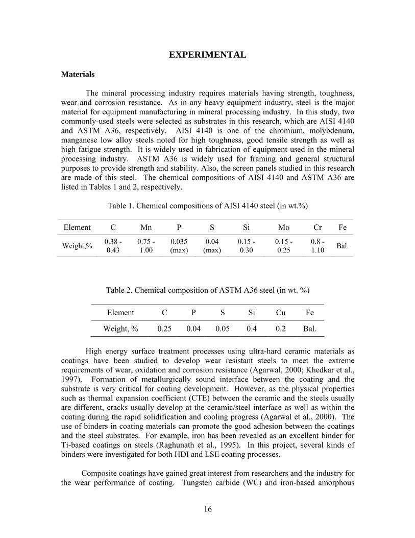
Figure 8. Allied TechCut10™ Abrasive Cut-Off Saw
The characterization specimens were cut from each sample by Allied TechCut10™ Abrasive Cut-Off Saw (Figure 8). The specimens were then mounted using epoxy resin with cross-section of coating-substrate interface exposed outside. The resin mounted specimen was easy to handle and ensured that the exact cross-section surface
21

should be polished. The mounted specimens were polished by mechanical grinding with a series of sand papers from coarse to fine (labeled with the following numbers: 200, 400, 600, 800, 1000 and 1200 grits). The purpose of this procedure was to remove the damages produced during cutting process. After the specimens were ground over the finest sand paper, the final step was to finish up on a polishing cloth with 0.3 μm alumina paste to obtain scratch free surfaces. This step was to remove any scratches or damage generated by the grinding.
Figure 9. Hitachi S-3200 SEM
The scratch free specimen surfaces were then etched to reveal the grain structure of the metallic phases. 2% Nital (98 ml ethanol + 2 ml nitric acid) was used as the etchant. The etchant did two things to the specimen surface. First, it chemically removed the deformed thin layer on the surface which was produced during the polishing process. Second, the etchant selectively attacked the highest energy sites on the surface without affecting the others. As a result, different crystal orientations, grain boundaries, precipitates, phases and defects were showed distinctly under the microscopy for the microstructure investigation. A Hitachi S-3200 scanning electron microscope (SEM, Figure 9) was employed to perform the microstructural characterization.
22
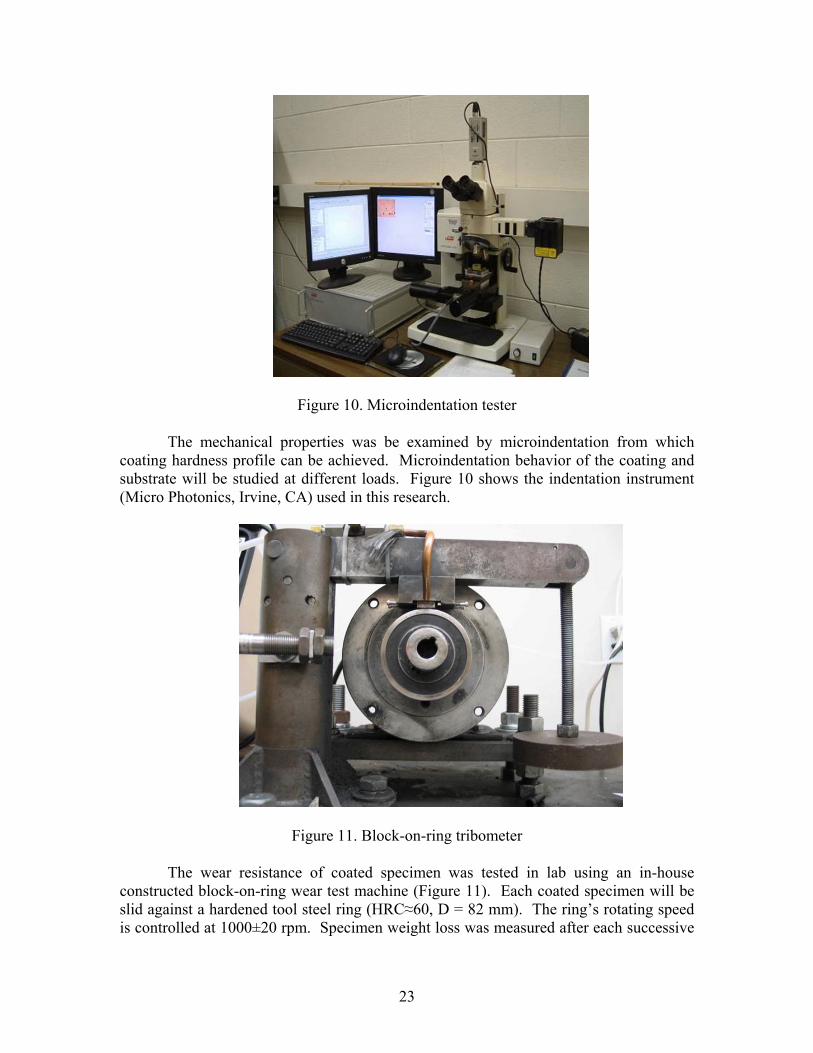
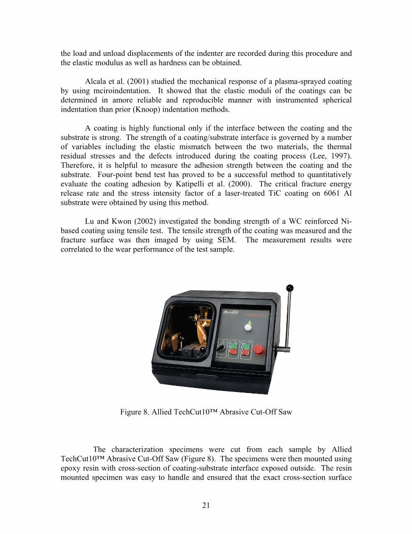
Figure 10. Microindentation tester
The mechanical properties was be examined by microindentation from which coating hardness profile can be achieved. Microindentation behavior of the coating and substrate will be studied at different loads. Figure 10 shows the indentation instrument (Micro Photonics, Irvine, CA) used in this research.
Figure 11. Block-on-ring tribometer
The wear resistance of coated specimen was tested in lab using an in-house constructed block-on-ring wear test machine (Figure 11). Each coated specimen will be slid against a hardened tool steel ring (HRC≈60, D = 82 mm). The ring’s rotating speed is controlled at 1000±20 rpm. Specimen weight loss was measured after each successive
23

2 minutes for a total test duration of 20 minutes. A normal load of 10 lbs (4.54 kg) was applied on the specimen during the test.
On-site Testing
The coatings that exhibited excellent wear performance in laboratory were selected for preliminary industrial trials. It should be noticed that laboratory testing is no substitute for in-service experience due to the increased complexity of the operating environment. In this research, field testing of coated raw coal screen panels was performed at the Big Creek Processing Plant (Sidney, KY) of Massey Energy Company. Big Creek Processing Plant is a coal preparation operation with a processing capacity of 12 Mt of raw coal annually. The plant uses two screens for raw coal sizing process, each consisting of 40 panels (Figure 12). The raw coal screen panels provided by Sidney Coal were made of ASTM A36 steel with a dimension of 1.21 m × 0.3 m × 6 mm. The opening size of the panel is 50 mm × 13 mm.
.
Figure 12. On-site test of coated screen panel
During the research period, 9 LSE-processed screen panels were tested at Big Creek Plant. Each time, the test panel was installed on the high-wear position, as shown in Figure 12, of one of the two raw coal screens in the plant. Figure 13 presents a sample coated screen panel used in the research.
24

Figure 13. Coated screen panel for on-site testing
One screen handles around 800 ton/hr raw coal. The screen operates 24 hours/day, and the plant is shut down 12 hour for maintenance every week. Weight loss of the test panel and size variations of specified openings on the test panel, as schematically shown in Figure 14, were measured every other week.
Figure 14. Schematic of a test raw coal screen panel
25

RESULTS AND DISCUSSION
Microstructure of HDI-treated Samples
Figure 15 presents a typical cross sectional micrograph of the HDI-processed specimen. Three regions which are coating, HAZ (heat affected zone) and substrate can be easily identified. The presence of a transitional HAZ zone can be attributed to the high temperature attained during HDI treatment which austenitized the steel in the interfacial region, transforming it to martensite.
HAZ
substrate
coating
HAZ
substrate
coating
Figure 15. Micrograph of the coated sample
The microstructure of each HDI sample was investigated using optical microscopy, SEM and analyzed by EDS method. Figures 16 and 17 show the cross section images of Sample A1 to A3 and B1 to B3, which were taken by optical microscopy (OM). Sample A1, A2 and A3 were WC coatings prepared by the HDI process. The common characteristic of the three coatings is that their thickness is relatively small. The coating thickness is not uniform along the interface for each of Sample A1, A2 and A3.
The rest of the samples, B1 B2 and B3 are all amorphous coatings prepared by HDI. It seems all the coatings were metallurgically bonded to the substrate. More detailed structure information would be revealed on the SEM images. It can be seen that the coatings were unevenly adhered to the substrates. Coating on Sample B1 was not continuously bonded with substrate. Sample B2 had a relatively thick coating compared with Sample B1 and B3.
For Sample B1 and B3, it can also be found that the upper part of each coating is more even than its bottom part. This can be explained by the different reaction intensities between the coating and substrate, i.e. higher reaction intensity results in deeper
26

penetration of the coating to the substrate layer. But even for the same coupon surface, the reaction intensity is not uniform for different locations which can lead to structure heterogeneity of coatings.
Figure 16. OM images for Sample A1, Sample A2 and Sample A3
27

Figure 17. OM images for Sample B1, Sample B2 and Sample B3
28

Figure 18. OM images of Sample Y1, Y2 and Y3
29

Figure 18 shows optical microscope images of screen section samples Y1, Y2 and Y3. with amorphous coatings. It is clear that Sample Y1 had more pores than Sample Y2 and Sample Y3. The distinct interface between coating and substrate can be seen in Sample Y1, which means the bonding was weak and the coating was easy to peel off. Sample Y2 and Sample Y3 had relatively uniform coating and no coating-substrate boundary.
SEM examinations were carried out to further investigate the microstructures of coatings and substrates. The cross section SEM morphologies of Sample A1 to A3 and B1 to B3 are shown in Figures 19 and 20. It can been seen from each SEM image that there are three regions marked as coating, interface (or heat affected zone) and substrate. During the HDI process, the materials located near the substrate-coating interface had metallurgical reactions to form some new materials as a result of the heat flux of the PAL which did not exist either in the substrate or coating before the process. The presence of heat affected zone with certain depth proved that the coatings were metallurgically bonded to the substrates. Generally, poor bonding between coating and substrate always degrades the coating adhesion strength. As a result, the coating may detach easily from the substrate, damaging its mechanical and tribological performance. The strong metallurgical bonds are known to significantly increase the coating-substrate adhesion strength.
In Figure 19, many bright islands were observed. These precipitations were agglomerate WC particles which were confirmed by EDS analysis. The WC particles sunk toward the bottom of the coating. Wu et al. (1995, 2004) also reported similar results. This phenomenon can be explained by the significant difference in the density between WC (15.6 g/cm3) and Ni-P (8.2 g/cm3). During the solidification of the transient coating, the heavier WC particles precipitated towards the bottom and formed the WC rich phase (the bright cluster). Another reason is Ni-P based materials melted faster than WC due to its low melting point under the high temperature processing conditions. WC particles melted relatively slow or even partially melted at beginning stage of the process. That’s why WC particles had the tendency to stay at the bottom of the molten metal.
For the Iron-based amorphous coatings (Figure 20), the distinct observation was that the coating thickness was higher than that of WC coatings. The coating of Sample B2 had the thickness of about 250 µm. There are some pores seen under SEM or even under low magnifications microscopy. The pores were initiated by thermal spraying prior to HDI process. During the thermal spraying, powders of coating material were sprayed onto the substrate. A lot of “splats” and “voids” were formed. The pores observed under the microscope can be in the form of trapped air or vacuum. In the subsequent step of the HDI process, some voids coalesced and collapsed. Some voids in the form of air were just trapped in the bulk materials. The splats were not always completely fused, which caused some defects and voids in the final coatings. It should be noted that the pores are weakest spots and can cause corrosion on the surface as a result of attack by some chemicals (Ahn et al., 2004). The direct effect of increased coating porosity is the reduction in coating density. In consequence it may damage the coating performance.
30

Figure 19. SEM images for Sample A1, Sample A2 and Sample A3
31

Figure 20. SEM images for Sample B1, Sample B2 and Sample B3
Figure 21 shows the SEM images of Sample Y1, Y2 and Y3 that were obtained to further investigate the microstructure of the coatings. The three regions named as coating, interface and coating were observed. The substrate and the coating were metallurgically bonded. But both Sample Y1 and Sample Y2 had high porosity. The pores are the weakest regions in the coating and are susceptible to corrosion attack. When the abrasive wear happens, the coating with high porosity is loose and tends to show a faster wear rate. The coating of Sample Y3 was more uniform and no large pores
32

were observed. Based on the visual observation, the quality of Sample Y3 coating was much better than that of Sample Y1 and Y2.
Figure 21. SEM images of Sample Y1, Y2 and Y3
EDS analysis was performed at different depths of coating and substrate to examine their elemental compositions. Figure 22 gives the EDS result of the substrate materials, AISI 4140 steel. The peaks obtained are very close to the standard AISI 4140 compositions (Table 1), except that the peaks for Mo were not detected in our study.
33

C: 7.62% Si: 0.26% Cr: 1.07% Mn: 0.71% Fe: 89.04% Ni: 1.30%
Figure 22.The EDS result of AISI 4140 steel
EDS tests were also performed on all the coatings to investigate elemental distribution in the coatings. For the white clusters in Sample A1, A2 and A3 with WC coatings, high content of tungsten element was detected in the EDS results. The data in Table 6 further indicate that tungsten and carbon are the main compositions in the white islands, which confirmed that those white phases were partly dissolved or precipitated WC particles. The presence of Fe was due to the dissolution of Fe from AISI 4140 steel substrates and small amount of Ni came from the Ni-P binder in the powder precursor.
Table 6. EDS results for WC rich cluster
Sample C, wt% Fe, wt% Ni, wt % W, wt% A1 11.09 12.87 1.76 74.27 A2 8.12 9.56 3.94 78.38 A3 9.58 2.36 0.95 87.12
EDS analyses were conducted in the non-WC rich areas (the coating matrix) to show the general element distribution in the coatings. The EDS results are listed in Table 7. In the non-WC rich area, the higher content elements were Fe and Ni.
34

Table 7. EDS results for the Matrix of WC coatings
Sample C, wt% Fe, wt% Ni, wt% W, wt% A1 6.86 61.94 25.49 4.55 A2 8.93 55.80 24.17 3.21 A3 8.94 40.42 33.75 2.36
It can be found from Table 7 that in the three specimens with WC coatings, high content of iron existed in the coating matrix. However, the iron was not included in the precursor powder before coating processing. The explanation for the presence of iron element in coating matrix is that Fe diffused rapidly in the coating. During the HDI process, the coating became liquid when fused by powerful plasma arc lamp. A thin layer of substrate materials melted under the heat flux of the PAL and Fe diffused from the substrate to the coating. The non-consistent element distribution means that coating regrouped itself during the HDI process, generating different phases. The hard WC precipitations may act as reinforced phases and increase the wear resistance of the coating.
Table 8. EDS results for amorphous coatings
Sample C, wt% Fe, wt% Cr, wt% Mo, wt% B1 7.84 84.85 3.69 1.85 B2 9.47 67.88 10.37 11.81 B3 8.3 77.16 7.22 5.92
Table 8 shows the element compositions of Sample B1, B2 and B3. In the three amorphous coatings, typical elements of iron-based coating such as Cr and Mo were detected. The content of iron increased from 50% in the coating precursor to around 70% in the final coating, which must be migrated from substrate materials during the HDI process. The contents of Cr and Mo decreased compared with powder precursor.
Microstructure of LSE-treated Samples
Figures 23, 24 provide a typical LSE-treated AISI 4140 steel coupon and a coated screen section, respectively. The coupon showed a resultant texture of typical laser processed surface with laser tracks on.
35

Figure 23. AISI 4140 coupon with (Ni-10P)-50TiB2 coating
Figure 24. Screen section with (Ni-10P)-50TiC coating
The coated samples were imaged cross-sectionally by using optical microscope. Figure 25 shows a typical OM image obtained on Sample S3 (Screen section, (Ni-10P)-50TiB2). It can be seen that a uniform coating layer was formed on the substrate and the coating thickness is about 150 - 200 μm, depending on the location of measurement, i.e.,
36

thicker coating is formed at the location where two adjacent tracks overlaps, which results in more heat flow into the substrate, increasing the depth of laser affected zone.
Figure 25. OM image of Sample S3
Figure 25 also demonstrates the convention pattern of the LSE process. During laser surface coating process, due to the high temperature generated by laser a melting pool is formed which includes both coating precursor powder and materials from the surface of treated surface. This allow the material transportation possible, e.g., it will be shown in the following section that iron from the substrate was transferred to the coating layer due to this convection effect.
Careful examination of the coating/substrate interfacial area indicates that there exists a clear microstructure evolution from coating, HAZ (Heat Affected Zone) to substrate, as shown in Figure 26. The presence of HAZ induces mechanical and structural modifications around the laser scanning area as well as the coating properties.
To further investigate the microstructures of coatings and substrates, SEM examinations were carried out. The cross section SEM morphologies of Sample C1 and C3 are shown in Figures 27 and 28, respectively. It can be seen from each SEM image that there are three regions marked as coating, interface (or heat affected zone) and substrate. The presence of heat affected zone with certain depth proved that the coatings were metallurgically bonded to the substrates. Generally, poor bonding between coating and substrate always degrades the coating adhesion strength. As a result, the coating may detach easily from the substrate, damaging its mechanical and tribological performance.
37

The strong metallurgical bonds are known to significantly increase the coating-substrate adhesion strength.
Figure 26. Microstructure evolution of the coated sample
A close-up of the coating layer suggests that TiC/TiB2 particles distribute uniformly in the coating area. The coating overall coating hardness can be increased by the presence of uniformly distributed Ti-based hard ceramics.
Figure 27. SEM image of Sample C1
38

Figure 28. SEM image of Sample C3
Figure 29. SEM image of Sample S3 (Overview)
39

Figure 30. SEM image of Sample S3 (Interfacial area)
Also, similar observation was obtained on the coated screen sections, e.g., Figure 22 provides the SEM image made on Sample S3 which is a coated screen section with (Ni-10P)-50TiB2 coating. A uniform and crack-free coating was obtained with a metallurgically sound interface, indicating the good wetting of the substrate by the coating. It should be mentioned that the coefficients of thermal expansion (CTE) of TiB2 and ASTM A36 steel are 6.39×10⁻⁶/K. and 6.5×10⁻⁶/K, respectively. The close CTE values of the two materials contribute to the formation of a uniform TiB2 coating on ASTM A36 steel during the laser treatment and result in much lower residual stresses in the finished product.
The SEM mircrograph of the coating-substrate interface of Sample S3 is showed in Figure 29. The presence of a continuous interfacial region indicates the coating was metallurgically bonded to the substrate. Coatings with this structure are expected to perform in a superior manner for wear applications as the chances of the coating delaminating are significantly reduced. The dendritic growth into the coating and martensite structure were observed in the interfacial region. This can be attributed to the rapid heating and cooling rates of the laser coating process (Agarwal and Dahotre,1999). It can be speculated that due to the high temperature attained in the laser treatment, the steel in the interfacial region can complete austenitization and transform to martensite, as shown in Figure 30.
40

Figure 31. EDS spectrum of Sample C1 (Near coating surface)
Due to the fact that most coatings are not homogenous in nature, esp. after treating by high energy processes such as LSE, therefore, the chemical compositions detected by EDS at different positions are usually different. For example, Figure 31 gives the EDS spectrum taken near the coating surface of Sample C1. High amount of Ti was detected in this area. However, the amount of Ti element decreases along the coating depth. EDS measurements taken near the coating/substrate interface zone present much lower Ti% but significant amount of Fe, as shown in Figure 32.
Figure 32. EDS spectrum of Sample C1 (Near interface zone)
41

Another interesting phenomenon is Fe was detected in the coating layer, as
demonstrated in Figure 32. However, Fe was not included in the precursor powder before coating processing. The explanation for the presence of Fe element in coating matrix is that Fe from the substrate diffused in the coating. During the LSE process, the coating became liquid when fused by the laser. A thin layer of substrate materials melted due to the high temperature and Fe diffused from the substrate to the coating. Some Fe transferred to the up portion of the coating layer due to the convection effect discussed earlier.
Figure 33. EDS spectrum of Sample S3 (Near coating surface)
42

Figure 34. EDS spectrum of Sample S3 (Near interface zone)
EDS tests were also performed on the coated screen sections and similar results were also observed. For example, higher amount of Ti was found near the coating surface whilst higher Fe was detected near the coating/substrate area, as shown in Figures 26 and 27.
Microhardness
The microhardness tests were performed with a Vickers microhardness tester. The Vickers hardness values were calculated using the load and the diagonal length of the indent. The microhardness profiles of Sample A1, A2 and A3 are shown in Figure 35 which illustrates that the microhardness of coating was much higher than that of AISI 4140 steel substrate. It was very obvious that the coating processed by HDI technology increased the surface hardness of the materials. As shown in Figure 35 for the three WC coatings, Sample A3 exhibited the highest microhardness which is about four times higher than that of the substrate materials.
43

Figure 35. Microhardness profile of HDI samples (A1-A3)
As shown in Figure 36, microhardness was also enhanced by amorphous coatings. The highest coating microhardness value occurred with Sample B3. It was also noted that the differences in coating hardness with the three amorphous coatings were not significant. Another observation from the microhardness profile curves was that the microhardness of WC coatings is higher than that of the amorphous coatings. There are two reasons for that. One was that the hard WC precipitations enhanced the WC coating hardness. The other was related to the defects and pores in the amorphous coatings formed during thermal spray and following HDI fusing.
44

Figure 36. Microhardness profile of HDI samples (B1-B3)
Figure 37. Microhardness profile of Sample S3
It is also noted that the microhardness values exhibited fluctuations during measurement. This is mainly caused by the heterogeneousity of materials (discrete distribution of WC in Fe-matrix for WC coatings and presence of porosity/voids in amorphous coatings). Other factors such as the equipment accuracy, methods etc. may also contribute to the fluctuations in microhardness.
45

Microhardness of LSE samples were also measured using the Vickers microhardness tester. The Vickers hardness values were calculated using the load and the diagonal length of the indent. For example, Figure 37 provides the microhardness profile of Sample S3. One can see that there is a gradual decrease in microhardness values from the coating to the substrate. The average coating hardness is around 830HV, whereas it deceases to 185HV in the substrate. The average microhardness at the interfacial and the heat-affected-zone (HAZ) is 300HV and 235HV, respectively. TiB2 is a hard material. The microhardness of pure TiB2 is about 3200HV (Cutler, 1995), whereas the coating micronhardness values obtained in the present study are significantly lower than that. This is mainly because the coating is composite in nature. Other possibilities include the formation of additional phases. For example, as stated earlier, Fe from the substrate and B can exist in the form of FexBBy which has a lower microhardness than TiB2. Therefore, microhardness indentations obtained in this study basically represented the average hardness of the different phases. All the other test samples also presented a similar hardness profile and they will not be depicted here. The Vickers indentations made during the microhardness measurements were imaged and one example is shown in Figure 38. It can be clearly seen that the size of indentations in the coating is much smaller than that on the interface and in the substrate, which is in agreement with the microhardness data. Careful examination of the indentation on the interface also shows that no crack initiation or propagation is seen, indicating the high cohesive strength of the coating/substrate interface.
Figure 38. Image of microindentions (Sample S3)
Lab Wear Testing
Block-on-disk wear test was adopted to evaluate the wear resistance of all the coatings processed by HDI coating technology. During the block-on-disk tests, the
46

weight loss with respect to the wear test duration for each specimen was recorded and shown in Figure 4.8 and Figure 39. The wear resistance properties of all the coated specimens were better than that of uncoated AISI 4140 steel. Of all WC coatings, Sample A3 showed the highest wear resistance and Sample B2 had the best wear resistance in the amorphous coating group. Comparing Sample A3 with Sample B2 indicates that A3 had a higher wear resistance. It seems that WC coatings were more effective in enhancing the wear resistance of AISI 4140 steel than amorphous coatings.
Figure 39. Block-on-disk wear test results of HDI samples A1, A2 and A3
47

Figure 40. Block-on-disk wear test results of HDI sample (B1, B2 and B3)
Figure 41. Block-on-ring test results of Sample C1-C4
48

Figure 42. Block-on-ring test results of Sample S1-S4
Block-on-disk wear test was conducted to evaluate the wear resistance of the LSE-coated specimens. During the block-on-disk tests, the weight loss with respect to the wear test duration for each specimen was recorded and shown in Figures 41 and 42, respectively. The wear resistance properties of all the coated specimens were better than that of uncoated AISI 4140 steel and ASTM A36 steel. Of all coated AISI 4140 specimens, Sample C3 showed the highest wear resistance and Sample S1 exhibited the best wear resistance in the coated screen section group. The wear resistance, in terms of weight loss, of these two steels were significantly enhanced by applying Ti-based ceramic coatings. It can be seen that the wear resistance of raw coal screen panel was increased for a factor of more than one magnitude, suggesting the proposed technology has great potential applications in the surface wear resistance of coal preparation equipment.
Sliding wear, by definition, is referred to as the wear due to the relative motion in the tangential plane of contact between two solid bodies (ASTM, 2003). Raw coal screening is a continuous process in a coal preparation plant and screens are subject to wear as coal particles travel on the panels. Low wear rate and stable wear behavior are expected for a wear resistant screen. During a sliding wear process, the asperities of the weaker material may shear off first and transfer to the opposite surface (Kelly et al, 1998). It can be observed that the wear rate of the coated specimen was stable during the test, indicating breaking-off of the hard coating materials is a very smooth process, which is in agreement with the high toughness of the coating.
49

It should also be mentioned that during the raw coal screening process in a coal preparation plant, coal particles are fed onto the screen panels tangentially at a given speed (e.g., 10-20 cm/s in Big Creek Processing Plant). These particles then either pass through or remain on the screen decks, resulting in wear of the panel surface. In the meantime, the screen deck itself vibrates vertically to improve the probability for undersize coal particles to pass through the screen and report to the undersize product stream. Coal particles bounce up and down on the panel surface as they travel to the discharge end, which leads to impact wear when particles hit the screen panel. Therefore, screen wear in the real world consists of both sliding and impact wear. However, the vibrating amplitude of a raw coal screen is usually within 3-5 millimeters, thus sliding wear still dominates during screening process which means the wear test method employed in this research is a suitable way to simulate the wear conditions. Additionally, the ring rotating speed in this test, about 880 cm/s, was considerably higher than the travel speed of coal particles on the screen surface. A normal load of 4.54 kg was applied on the test screen section with a small contact area of 1.6×10⁻⁴ m2. This was needed to create a rapid wear rate of the specimen.
On-site Testing
As stated earlier, on-site testing has been conducted at a coal prep plant using totally 9 raw coal screen panels. Three LSE-treated test panels, No. 7, No.8 and No.9 showed longer wear life than other 6 coated panels during the tests. Metco 12C (Cr 10%, Boron 2.5%, Iron 2.5%, Si 2.5%, Carbon 0.15% and Nickel (Balance)) was the coating material used on Panels No. 7 and No.8 and TiBB2 coating, (Ni-10P)-50TiB2, wt%, was applied on Panel No.9. LSE processing parameters of these three panels were listed in Table 9 as below.
Table 9. Three test panels
Test Panel Coating Laser power, W Laser Speed, mm/min
No.7 Metco 12 C 2000 1500 No.8 Metco 12 C 2400 4500 No.9 (Ni-10P)-50TiBB2 1250 1500
Table 10 shows the field testing results of three coated screen panels that showed longer wear life in field testing. It is known that the service life of an uncoated screen panel at the high wear position of the raw coal screen is about 5 weeks at the plant, depending on the amount of coal processed. It can be seen that all the three panels outperformed the uncoated one in terms of service life. The high tonnages, range from 0.75 to 0.99 million tons, processed by the screen during test demonstrate the robustness of the three coated panels. If compared by wear rate which is defined as the ratio of test panel weight loss divided by the processing tonnage, No.9 showed the lowest wear rate among the three panels, which was about 50% of uncoated screen panel, as shown in Figure 43.
50

Table 10. On-site testing of three coated panels
Test Panel Date Installed Date Replaced Weight
Loss, lb
Processing tonnage, ton/screen
Wear Rate, (lb/ton)×10-7
No.7 7/27/2005 10/7/2005 9.26 993955 93.16 No.8 10/7/2005 11/28/2008 7.87 867321 90.74 No.9 2/16/2006 4/5/2006 6.61 747384 88.44
Figure 43. Wear rates of the test panels
Figure 43 compares a test panel before and after test. It can be seen that the screen slots have deformed from the initial square to trapezoid-shaped after the test. The mainly reason is coal particles hit the bar between two adjacent slots and the thus the wires become thinner due to wear caused by the moving coal particles. Therefore, the wire between two slots is the most vulnerable part of a screen panel.
51

Figure 44. Test panel (Left:before test; Right: after test)
As mentioned earlier that the opening size change of specified apertures were measured for each test panel, which can be translated into slot area change. A “slot area increase rate” is proposed which is defined as the area ratio of a slot after and before test. For the purpose of comparison, the area change ratios of four rows, Row 2, 10, 20 and 30, are shown in Figure 45 to 48.
It can be seen that for all the three test panels, the area increase of the slots in the upper portion (close to feeding end) is higher than that of the lower portion (close to discharge end). This is due to the fact that slots close to the feeding end are subjected to processing more materials than that on the discharge end, which, in turn, creates more wear on the upper portion of the screen panel. Another finding, on each panel, the size change (area increase) of the slots on the second column is higher than that of the other three measured slots. This is because the test panel was installed right next to the wall and coal particles hit the wall and bounced back to the panel on approximately the second column.
52

0
5
10
15
20
25
30
35
40
0 1 2 3 4 5 6 7
Column No.
Slot
Are
a In
crea
se, %
8
No.9No.7No.8
Figure 45. Slot area change of Row 2
0
5
10
15
20
25
30
35
40
0 1 2 3 4 5 6 7 8 9Column No.
Slot
Are
a In
crea
se, %
No.7No.9No.8
Figure 46. Slot area change of Row 10
53

0
5
10
15
20
25
30
35
40
0 1 2 3 4 5 6 7 8 9Column No.
Slot
Are
a In
crea
se, %
No.7No.8No.9
Figure 47. Slot area change of Row 20
0
5
10
15
20
25
30
35
40
0 1 2 3 4 5 6 7 8 9Column No.
Slot
Are
a In
crea
se, % No.7
No.8No.9
Figure 48. Slot area change of Row 30
As shown in Figure 45, the wires between two adjacent slots are the most vulnerable part on the screen. Actually, although the screen panel was replaced after putting in service for some time, the laser tracks can still be seen on the panel (Figure 44) and the slots close to the discharge end almost stayed intact, e.g., the slot area change of
54

the Row 30 of Screen No.9 is only about 5% (Figure 48), suggesting the high toughness of the surface coating. If the wear resistance of the slots near the feeding end can further improved, the service life of a coated panel will be greatly improved. Coating the wires and inner wall of the slots has been thought to be a solution to this issue.
It should be noted that the in-service wear conditions are much more complicated than that of the laboratory wear test. In realities, a component usually fails by a mixture of wear modes, which makes it difficult to simulate in the lab testing.
55

PROJECTED ENERGY BENEFITS
As stated in the previous sections, steels with extended wear service life can be obtained through the application of the proposed HDI and LSE surface coating technologies developed in this project. Based on the lab and on-site testing results achieved through this project, if the technology developed in this projected is commercialized and successfully applied in the mining sector of the United States, a significant amount of energy can be saved annually.
To calculate the potential energy savings these coating technologies can bring to the mining industry, the following assumptions have been made:
1. 100% market penetration; 2. Coated equipment service life will be extended 2 times by using the coating
technology; 3. Raw coal screen was considered as an example in the energy saving calculation
and each panel needs 25 lbs of steel to manufacture; 4. 1% increase in coal/mineral processing plant efficiency and 1% increase in
recovery as a result of increased equipment wear resistance; 5. U.S. annual coal production = 1.1 billion tons, 70% of which needs to be
processed; 6. U.S. annual industrial mineral production = 3.1 billion tons; 7. U.S. annual metal mineral production = 150 million tons; 8. Average mineral/coal processing plant energy consumption: 14 kWh/t coal; 47
kWh/t hematite ore; 85 kWh/t, magnetite ore; 67 kWh/t phosphate mineral; 2.4 kWh/t aggregate;
9. Average Btu value of coal: 11,000 Btu/lb; 10. Electricity cost: $0.051/kWh; 11. 1 kWh=3.4×10³ Btu; 12. 500 kW of electricity is needed to be consumed to produce one ton of steel; 13. Average mineral/coal processing plant energy consumption: 14 kWh/t coal, 60
kWh/t metal and 3 kWh/t industrial mineral industry; 14. 1% coal recovery and plant efficiently can be achieved due to the application of
the proposed surface coating technologies.
According to the practice of Big Creek Plant, about 200 raw coal screen panels are consumed annually in this particular plant to process 1.36×10⁶ tons of coal. Raw coal production in the US was 1,661.44 million tons in 2006. Therefore, it can be calculated that 2.3×10⁹ Btu per year is needed to produce regular steel panels alone in the US. If the screen service life is doubled through the application of the surface coating technology, then 1.65×10⁹ Btu of energy can be saved due to the reduced amount of screen panels needed in the industry.
On the other hand, processing one screen panel using the LSE method requires about 1.76 kW energy, therefore, 3.59×10⁸ Btu is needed to apply wear resistant surface coating onto the screen panels, i.e., total energy requirement for coated screen
56
manufacturing is 1.65×10⁹+ 3.59×108 = 1.51×10⁹ Btu. Thus, compared with the use of uncoated screen panels, (2.3×10⁹ - 1.51×10⁹)= 1.15×10⁹ Btu can be saved by adopting LSE-treated screen panels alone in the coal preparation industry.
As explained earlier in this report, coal preparation includes several unit processes in which screening is only one of the major processes. We can assume that similar energy benefits can be obtained if the technology is applied to other major coal preparation devices such as separators, pipes, etc. Then the total energy savings in the whole coal preparation section will be at least tripled. Besides, if mineral and aggregate industries are considered and similar benefits apply, it will finally lead to a total energy savings of 1.15×109×3×3=1.36×10¹⁰ Btu per year.
Considering the energy savings generated by the 1% increase of coal recovery gives 11000 Btu/lb×2000 lb/t×1.1×109 t/yr×1% =1.58×10¹⁴ Btu. In the meantime, 1% increase in plant efficiency will lead to electricity saving:
Coal industry: 14kWh/t×1.1×109t/yr×3.41×103 Btu/kWh×1%=6.851×1010 Btu/yr; Metal mineral industry: 60kWh/t×1.5×108t/yr×3.41×103Btu/kWh×1%= 6.12
×1010 Btu/yr; and Industrial mineral industry: 3kWh/t×3.1×109t/yr×3.41×103Btu/kWh×1%=
6.32×10¹⁰ Btu/yr.
Therefore, total energy savings due to 1% increase of coal recovery and 1% improvement of plant efficiency is 1.585×10¹⁴ Btu per year. Combined with the 1.36×10¹⁰ Btu/yr savings resulted from less steel consumption, we have the projected total amount of energy savings of 1.585×10¹⁴ Btu every year.
57

CONCLUSIONS
Based on the results obtained in the present investigation, the following conclusions can be drawn:
1. Wear poses serious adverse influences on mineral processing and coal preparation industries. The main wear issues involved in mineral and coal processing have been analyzed and related wear mechanisms of each major mineral processing process were discussed. .
2. Two advanced high energy surface treatment methods including HDI and LSE have been developed and related test facilities were built. Both HDI and LSE proved to be effective ways to produce surface coatings with enhanced wear resistance.
3. Typical microstructural features of HDI-processed coating were observed in all the coatings, which includes coating zone, heat affected zone (HAZ) and substrate.
4. SEM characterization showed the HDI coatings were metallurgically bonded to the substrates.
5. The values of hardness of both WC and amorphous coatings are higher than that of substrate materials. The hardness of WC coating was up to three times higher that that of AISI 4140 steel and amorphous coating also achieved a three times higher hardness with the ASTM A36 steel.
6. Sample coated with (Ni-10P)-60WC on AISI 4140 steel by HDI (10 mm/s,
300A/700A), showed the best wear resistance in the WC coating group. The wear resistance increased up to 5 times compared to uncoated AISI 4140.
7. The EDS analyses showed the presence of WC particle and WC rich-phase.
The hard WC coatings significantly enhanced wear resistance of substrate AISI 4140 steel.
8. Of three amorphous coatings, Sample coated with amorphous coating Fe-
15Cr-14Mo-2Y-15C-6B, wt.%, on AISI 4140 steel by HDI (10 mm/s, 400A/800A) showed the best wear resistance. The wear life of AISI 4140 steel increased about 3 times by this amorphous coating.
9. For screen substrate, Sample coated with amorphous coating Fe-15Cr-14Mo-
2Y-15C-6B, wt.%, by HDI (10 mm/s, 800A) had the best wear resistance. The wear life of this coated materials increased about 5 times than the uncoated screen.
10. High porosity was observed with most HDI-processed coatings which
adversely affected coating performance.
58

11. In the HDI process, two scanning passes are preferred to wet the coating first
and then fuse at higher current to produce strong bonding and high density, high hardness coating.
12. A variety of coating materials have been formulated. Extensive lab tests were carried out to screen viable coatings for field testing. Among all the HDI-treated samples, AISI 4140 steel with (Ni-10P)-60WC coatings (10 mm/s, 300A/700A) showed a 5-fold wear resistance improvement compared to uncoated AISI 4140.
13. Of the coated AISI 4140 specimens processed by LSE, Sample C3 ((Ni-10P)-50TiB2,1250 W, 1500 mm/min) produced the highest wear resistance which is around 26 times higher that of the untreated AISI 4140 steel. Sample S1 ((Ni-10P)-50TiC, 1500 W, 1500 mm/min) and S3 ((Ni-10P)-50TiB2, 1250 W, 1500 mm/min) showed similar wear resistance enhancement during the wear test. The wear life of raw coal screen (ASTM A36 steel) increased about 10 times by applying these two coatings.
14. On-site test using coated screen panels exhibited significant improvement (about 2 times) of screen panel service life.
15. Energy saving estimation indicates that a considerable amount of energy can be saved by applying the proposed surface treatment technology. 1.585×10¹⁴ Btu energy benefit is anticipated to be obtained annually if the surface coating technology is commercialized.
59

REFERENCES
Agarwal, A., 1999, Laser surface engineering of composite titanium diboride coating on steel: synthesis and characterization Ph.D. dissertation, (Knoxville, TN: University of Tennessee, December 1999)
Agarwal, A. and Dahotre, N. B., 2000, Comparative wear in titanium diboride coatings on steel using high energy density processes, Wear, v 240, n 1-2, pp.144-151
Ahn, S.H., Lee, J.H., Kim, H.M. and Kim, J.G., 2004, “A study on the quantitative determination of through-coating porosity in PVD-grown coatings,” Applied Surface Science, 233 (1-4), pp. 105-114.
ASTM Standard, 2003a – Steel - Structural, Reinforcing, Pressure Vessel, Railway, Annual book of ASTM standards, Volume 01.04, p166. ASTM international, West Conshohocken, PA.
ASTM Standard, 2003b, Wear and Erosion; Metal Corrosion, Annual book of ASTM standards, Volume 03.02, p172, ASTM international, West Conshohocken, PA
Blue, C.A., Sikka, V.K., Ohriner, E.K., Engleman, P.G. and Harper, D.C., 2000, “High-density-infrared transient liquid coatings,” JOM-e, 52(1) http://www.tms.org/pubs/journals/JOM/0001/Blue/Blue-0001.html.
Blue, C. and Sikka, V., 2000, “Infrared transient-liquid-phase coating of materials,” Proceedings of the 7th PEWG Meeting, July 17-20.
Bull, S.J., 1997, Tribological and micro-tribological phenomena in coatings, Materials science forum 246, pp.105-122.
Chong, P.H., Man, H.C. and Yue, T.M., 2001, Microstructure and wear properties of laser surface-cladded Mo-WC MMC on AA6061 aluminum alloy, Surface and Coatings Technology, 145 (1-3), pp.51-59.
Cutler, R., 1995, “Engineering properties of borides” In Engineering Materials Handbook, Ceramic and Glasses. ASM International, Metals Park, OH, pp. 787–803.
Dahotre, N.B.,1998, in: Lasers in surface engineering, ASM International, Materials Park, OH.
Dowson, D.; Taylor, C. M., (1985), Survey of research on tribology and future priorities, Wear, v 106, n 4, pp.347-358
Durman, R.W., 1988, Progress in abrasion resistant materials for use in comminution processes, International Journal of Minereral. Processing, pp. 381–399
60

Engleman, P.G., Dahotre, N.B., Blue, C.A., Harper, D.C. and Ott, R., 2002, “High density infrared processing of WC/Ni-11P composite coatings,” Surface Engineering, 188(2), pp. 113-119.
Foster, J., 1996, Ceramic applications for wear protection of pipe lines and cyclones, Key Engineering Materials, 122-124, pp. 247-278.
Folkes, J.A., (1997), Surface modification and coating with lasers, Materials science Forum, v246, pp. 261-278
Foster, J.; (1996), Ceramic applications for wear protection of pipe lines and cyclones, Key Engineering Materials, v 122-124, pp. 247-278.
Kelly, J.; Nagarathnam, K.; Mazumder, J., 1998, Laser cladding of cast aluminum-silicon alloys for improved dry sliding wear resistance, Journal of Laser Applications, v 10, n 2, pp. 45-54.
Kembaiyan, K.T. and Kenshavan, K., 1995, ”Combating severe fluid erosion and corrosion of drill bits using thermal spray coatings,” Wear, 186-187(2), pp. 487-492.
Khedkar, J.; Khanna, A.S. and Gupt, K.M., 1997, Tribological behaviour of plasma and laser coated steels, Wear, v 205, n 1-2, pp. 220-227
Laurila, M.J., 1998, Trends in the U.S. coal preparation industry, Coal Age, 103(5), pp.53-54
Laurila, M.J. and Budge, G., 2000, “Benchmarking coal prep practice: An Update,” in Proceedings of 17th International Coal Preparation Exhibition & Conference, Lexington, KY, USA, pp. 51-55.
Leonard, J. W. and Hardinge, B.C., 1991, Coal preparation, 5th edition, Society for Mining, Metallurgy and Exploration, Inc., Littleton, CO, p 223.
Mazumder, J., 1996, Laser assisted surface coatings, in: Metallurgical and Ceramic Protective Coatings, ed. Kurt H. Stern, Champman and Hall, London, pp. 74-111
Muralidharan, G.; Blue, C.A.; Sikka, V.K.; Dahotre, N.B., (2004), Surface modification of 4340 steel with iron aluminides using high-energy-density processes, Materials Science and Technology, v 2: AIST/TMS Proceedings, pp 357-366
Mining Journal Ltd., 1999, Mining Annual Review, London, United Kindom.
Norman, T.E., 1980, Wear in ore processing machinery, in: Wear Control Handbook Peterson, M.B. and Winor, W.O. (Eds.), ASME, pp. 109–115
61

Nonnen, F.A., 1985, Wear resistant materials reduce costs, Bulk Solids Handling, 5(5), pp. 1035-1039.
Odawara, O., 1985, “Ceramic lined pipes produced by a centrifugal-thermit process,” Transaction of the Japan Institute of Metals, 26(8), pp. 578-586.
Odawara, O., 1996, “Ceramic linings of pipes using SHS technology,” Key Engineering Materials, 122-124, pp. 463-476.
Pang, S., Zhang, T., Asami, K. and Inoue, A., 2002, “Formation of bulk glassy Fe75-x-
yCrxMoyC15BB10 alloys and their corrosion behavior,” Journal of Materials Research, 17 (3), pp. 701-704.
Perrott, C.M., 1982, “Mining applications of thermal sprayed coatings,” International Journal of Powder Metallurgy and Powder Technology, 18(1), pp. 39-55.
Przybylowicz, J. and Kusinski, J., 2001, Structure of laser cladded tungsten carbide composite coatings, Journal of Materials Processing Technology 109(1-2), pp.154-160.
Raghunath, C.; Bhat, M.S.; Rohatgi, P.K. 1995, In situ technique for synthesizing Fe-TiC composites, Scripta Metallurgical Material, v 32, n 4, pp. 577-582
Steen, W.M., (1995), Surface Engineering with laser, Metals and Materials, v1, n12,
pp.730-792
Wang, L.L., Munir, Z.A., Maximov, Y.M., 1993, Thermite reactions : their utilization in the synthesis and processing of materials, Journal of Materials Science, 28 (14), pp, 3693-3708.
62