development of a web-based laboratory for control...
TRANSCRIPT

76 IEEE TRANSACTIONS ON EDUCATION, VOL. 44, NO. 1, FEBRUARY 2001
Development of a Web-Based Laboratory for ControlExperiments on a Coupled Tank Apparatus
C. C. Ko, Senior Member, IEEE, Ben M. Chen, Member, IEEE, Jianping Chen, Yuan Zhuang, andKay Chen Tan, Member, IEEE
Abstract—The Internet provides a new environment for de-veloping a variety of applications for educational and researchpurposes. This paper presents the implementation of a web-basedlaboratory experiment on a coupled tank apparatus, a Multi-input–Multioutput (MIMO) system. The web-based laboratoryhas been developed to serve students and staff in the Departmentof Electrical Engineering at the National University of Singapore(NUS). The laboratory is an educational tool for teaching studentsthe basic principles and methodology in performing a series of ex-periments on a coupled tank apparatus at any time and from anylocation through the Internet. With the capability to implementstrategies for manual, proportional integral derivative (PID),general state-space, and fuzzy logic control, the laboratory alsoprovides a platform for research staff to test control algorithms.Video conferencing has been used to provide audio and videofeedback, with a camera mounted on a movable platform so thatthe user can control both the zooming and viewing angle. The lab-oratory can be accessed at http://vlab.ee.nus.edu.sg/vlab/control/.
Index Terms—Internet, virtual laboratory, web-based control.
I. INTRODUCTION
T HE CONCEPT of a web-based laboratory is not new. Shorand Bhandari [2] developed a distance learning applica-
tion that allowed a user to remotely conduct experiments in theControl Engineering Laboratory at Oregon State University. Theapplication permitted the experiments to be run via the WorldWide Web (WWW). Only a basic web browser that ran Javais needed to gain access and a robot experiment was developedfor demonstration. Bytronic Process Control unit [3], referred toas the process rig in the Process Control and Automation Lab-oratory at Case Western Reserve University, can be accessedremotely via the Internet. Using a web browser, the user canlog on and post the parameters from a remote client to a Labo-ratory Virtual Instrument Engineering Workbench (LabVIEW,from National Instruments [6]) web server that is connected toa process rig via a programmable logic control (PLC) module.The image is generated by a program and refreshed on the clientside using server push technology. A remote laboratory calledVLAB [1] on an oscilloscope experiment was recently set up inthe Department of Electrical Engineering, National Universityof Singapore (NUS). These remote laboratories are actual lab-oratory experiments that are run remotely via a web interface,and are well suited to distance learning courses where studentsneed not be physically present on campus. They also facilitate
Manuscript received January 5, 2000; revised May 30, 2000.The authors are with the Department of Electrical and Computer Engineering,
National University of Singapore, Singapore 117576.Publisher Item Identifier S 0018-9359(01)01286-9.
Fig. 1. Laboratory setup of the equipment.
the sharing of expensive instruments and equipment, and repre-sent the next important step in remote distance learning.
In this paper, the implementation of a remote laboratory con-trol experiment on a coupled tank apparatus is presented. Fourcommonly used control structures (manual control, proportionalintegral derivative (PID) control, general state-space control,and fuzzy logic control) are implemented. The experiment cor-responds to an industrial control-related experiment for under-graduate and graduate students in NUS, with the virtual labora-tory also providing a platform for researchers to test control al-gorithms. LabView [6], Java, HTML (Hyper Text Markup Lan-guage), as well as scripting languages like JavaScript and VB-Script have been used in the implementation. A distinctive fea-ture is the provision of audio and video feedback through theuse of video conferencing based on Microsoft NetMeeting [8],with a camera mounted on a movable platform so that the usercan control both the zooming and viewing angle. The equipmentsetup of the laboratory is depicted in Fig. 1.
This paper is organized as follows. Section II describes thestructure of the virtual laboratory, including its hardware andsoftware structures. Discussion is given on the use of transmis-sion control protocol (TCP) as opposed to common gateway in-terface (CGI) for client–server communication as well as otherdistinctive features of the implementation from the point of pro-viding audio–visual feedback. Section III presents a model ofthe coupled tank apparatus. Section IV presents the structures ofthe different controllers that can be used and the correspondinguser interfaces. Conclusions are presented in Section V.
0018–9359/01$10.00 © 2001 IEEE
KO et al.: DEVELOPMENT OF A WEB-BASED LABORATORY FOR CONTROL EXPERIMENTS ON A COUPLED TANK APPARATUS 77
II. STRUCTURE OFVIRTUAL LABORATORY
A. Hardware Structure
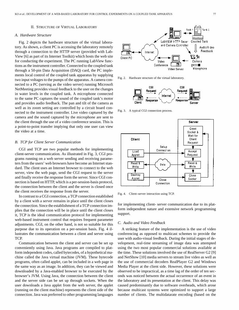
Fig. 2 depicts the hardware structure of the virtual labora-tory. As shown, a client PC is accessing the laboratory remotelythrough a connection to the HTTP server (provided with Lab-View [6] as part of its Internet Toolkit) which hosts the web sitefor conducting the experiment. The PC running LabView func-tions as the instrument controller. Connected to the coupled tankthrough a 50-pin Data Acquisition (DAQ) card, the PC imple-ments local control of the coupled tank apparatus by supplyingtwo input voltages to the pumps of the apparatus. A camera con-nected to a PC (serving as the video server) running MicrosoftNetMeeting provides visual feedback to the user on the changesin water levels in the coupled tank. A microphone connectedto the same PC captures the sound of the coupled tank’s motorand provides audio feedback. The pan and tilt of the camera aswell as its zoom setting are controlled by a circuit board con-nected to the instrument controller. Live video captured by thecamera and the sound captured by the microphone are sent tothe client through the use of a video conference session. This isa point-to-point transfer implying that only one user can viewthe video at a time.
B. TCP for Client Server Communication
CGI and TCP are two popular methods for implementingclient-server communication. As illustrated in Fig. 3, CGI pro-grams running on a web server sending and receiving parame-ters from the users’ web browsers have become an Internet stan-dard. The client uses an Internet browser to connect to the webserver, view the web page, send the CGI request to the serverand finally receive the response form the server. Since CGI con-nection is based on HTTP, which is a per-session-basis protocol,the connection between the client and the server is closed oncethe client receives the response from the server.
In contrast to a CGI connection, a TCP connection establishedby a client with a server remains in place until the client closesthe connection. Since the establishment of a TCP connection im-plies that the connection will be in place until the client closesit, TCP is the ideal communication protocol for implementingweb-based instrument control that requires frequent parameteradjustments. CGI, on the other hand, is not so suitable for thispurpose due to its operation on a per-session basis. Fig. 4 il-lustrates the communication between a client and server usingTCP.
Communication between the client and server can be set upconveniently using Java. Java programs are compiled to plat-form independent codes, called bytecodes, of a hypothetical ma-chine called the Java virtual machine (JVM). These bytecodeprograms, often called applet, can be included in a web page inthe same way as an image. In addition, they can be viewed anddownloaded by a Java-enabled browser to be executed by thebrowser’s JVM. Using Java, the connection between the clientand the server side can be set up through sockets. When theuser downloads a Java applet from the web server, the applet(running on the client machine) represents the client side of theconnection. Java was preferred to other programming languages
Fig. 2. Hardware structure of the virtual laboratory.
Fig. 3. A typical CGI connection process.
Fig. 4. Client–server interaction using TCP.
for implementing client- server communication due to its plat-form independent nature and extensive network programmingsupport.
C. Audio and Video Feedback
A striking feature of the implementation is the use of videoconferencing as opposed to multicast schemes to provide theuser with audio-visual feedback. During the initial stages of de-velopment, real-time streaming of image data was attemptedusing the two most popular commercial solutions available atthe time. These solutions involved the use of RealServer G2 [9]and NetShow [10] media servers to stream live video as well asthe use of commercial decoders RealPlayer G2 and WindowsMedia Player at the client side. However, these solutions wereobserved to be impractical, as a time lag of the order of ten sec-onds was noticed between the actual occurrence of an event inthe laboratory and its presentation at the client. This delay wascaused predominantly due to software overheads, which arosebecause multicast systems were optimized to support a largenumber of clients. The multidatarate encoding (based on the
78 IEEE TRANSACTIONS ON EDUCATION, VOL. 44, NO. 1, FEBRUARY 2001
bandwidth available to the target audience), Buffering (duringnetwork congestion) and intelligent transmission (maintainingcontinuity of video at the expense of quality during networkcongestion) features of the multicast schemes were also iden-tified as potential bottlenecks.
Since the NUS campus network, NUSNET-III [11], providesthe user with bandwidth comparable to a T1 connection,bandwidth is not a constraint for the implementation of remotelaboratory experiment within the campus and video confer-encing was adopted to provide live video to the client. For thispurpose, Windows NetMeeting 3.0 was chosen. NetMeetinguses the H.323 standard, which is comprised of InternationalTelecommunications Union (ITU) approved protocols foraudio, video, and data conferencing over TCP/IP networks. Thestandard is compatible with H.261 and H.263 video codecs.
As NetMeeting 3.0 also supports the transfer of audio, a mi-crophone connected to the instrument controller is used to cap-ture the sound made by the coupled tank’s motor. The latter canthen be heard at the client side by attaching speakers to the clientcomputer. This feature is intended to provide the user as realistica feel as possible while performing the experiment.
The implementation uses an ActiveX control to embed thelive audio and video on web pages. This control is part of theWindows NetMeeting Resource Kit [12], and is invoked andcontrolled using VBScript, a scripting language developed byMicrosoft Corporation. When the user activates ActiveX andcalls the video server (explicitly by specifying the IP (InternetProtocol) of the video server), a call is placed. The NetMeetingprogram on the video server is configured to receive calls imme-diately without any user intervention on the server side to acceptthe call. The program is also configured to send out live audioand video at the start of each call. The audio and video at theclient side can be stopped in a similar manner through endingthe call or clicking the “Stop A/V” button.
From the above, it is apparent that only one user can receivevideo at a time. This is logical since only one user is allowedto access the web-based laboratory at a time. In fact, this singleuser feature is implemented by restricting access to the experi-ment’s web pages. The user is authenticated by a CGI programresiding on the HTTP server, and can access the web pages forperforming the experiment if no one else is carrying out the ex-periment.
D. Camera Control
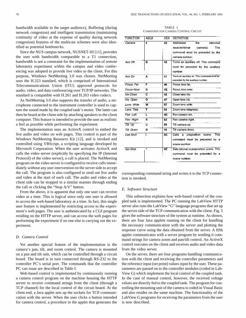
Yet another special feature of the implementation is thecamera’s pan, tilt, and zoom control. The camera is mountedon a pan and tilt unit, which can be controlled through a circuitboard. The board is in turn connected through RS-232 to thecontroller PC’s serial port. The commands that the controllerPC can issue are described in Table I.
Web-based control is implemented by continuously runninga camera control program on the machine housing the HTTPserver to receive command strings from the client (through aTCP channel) for the local control of the circuit board. At theclient end, a Java applet sets up the sockets for TCP communi-cation with the server. When the user clicks a button intendedfor camera control, a procedure in the applet that generates the
TABLE ICOMMANDS FOR CAMERA CONTROL CIRCUIT
corresponding command string and writes it to the TCP connec-tion is invoked.
E. Software Structure
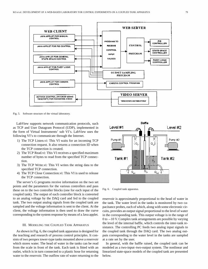
This subsection explains how web-based control of the cou-pled tank is implemented. The PC running the LabView HTTPserver also runs the LabView “G” language programs that set upthe server side of the TCP communication with the client. Fig. 5gives the software structure of the system at runtime. As shown,there are four Java applets running on the client for handlingthe necessary communication with the server and plotting theresponse curve using the data obtained from the server. A fifthapplet communicates with a server program by sending it com-mand strings for camera zoom and pan/tilt control. An ActiveXcontrol executes on the client and receives audio and video datafrom the video server.
On the server, there are four programs handling communica-tion with the client and receiving the controller parameters andthe reference input (set point) values input by the user. These pa-rameters are passed on to the controller modules (coded in Lab-View G) which implement the local control of the coupled tank.In the case of manual control, however, the received voltagevalues are directly fed to the coupled tank. The program for con-trolling the mounting unit of the camera is coded in Visual Basicand also resides on the same machine. The functionality of theLabView G programs for receiving the parameters from the useris now described.
KO et al.: DEVELOPMENT OF A WEB-BASED LABORATORY FOR CONTROL EXPERIMENTS ON A COUPLED TANK APPARATUS 79
Fig. 5. Software structure of the virtual laboratory.
LabView supports network communication protocols, suchas TCP and User Datagram Protocol (UDP), implemented inthe form of Virtual Instruments’ sub VI’s. LabView uses thefollowing VI’s to communicate through the Internet.
1) The TCP Listen.vi: This VI waits for an incoming TCPconnection request. It also returns a connection ID whenthe TCP connection is created.
2) The TCP Read.vi: This VI receives a specified maximumnumber of bytes to read from the specified TCP connec-tion.
3) The TCP Write.vi: This VI writes the string data to thespecified TCP connection.
4) The TCP Close Connection.vi: This VI is used to releasethe TCP connection.
The server’s G programs receive information on the two setpoints and the parameters for the various controllers and passthese on to the two controller blocks (one for each input of thecoupled tank). The output of each controller block is convertedto an analog voltage by the DAQ card and fed to the coupledtank. The two output analog signals from the coupled tank aresampled and the voltage information is sent to the client. At theclient, the voltage information is then used to draw the curvecorresponding to the system response by means of a Java applet.
III. M ODELING THE COUPLED TANK APPARATUS
As shown in Fig. 6, the coupled tank apparatus is designed forthe teaching and research of process control principles. It con-sists of two perspex tower-type tanks mounted above a reservoirwhich stores water. The head of water in the tanks can be readfrom the scale in front of the tank. Each tank is fitted with anoutlet, which is in turn connected to a plastic hose for returningwater to the reservoir. The outflow rate of water returning to the
Fig. 6. Coupled tank apparatus.
reservoir is approximately proportional to the head of water inthe tank. The water level in the tanks is monitored by two ca-pacitance probes, each of which, along with some electronic cir-cuits, provides an output signal proportional to the level of waterin the corresponding tank. This output voltage is in the range of0 to 10 V. Complex tank arrangements are possible by varyingthe level of the internal baffle, which controls the inter-tank re-sistance. The controlling PC feeds two analog input signals tothe coupled tank through the DAQ card. The two analog out-puts corresponding to the water level in the tanks are sampledat a rate set by the user.
In general, with the baffle raised, the coupled tank can bemodeled as a two-input–two-output system. The nonlinear andlinearized state-space models of the coupled tank are presentedbelow.
80 IEEE TRANSACTIONS ON EDUCATION, VOL. 44, NO. 1, FEBRUARY 2001
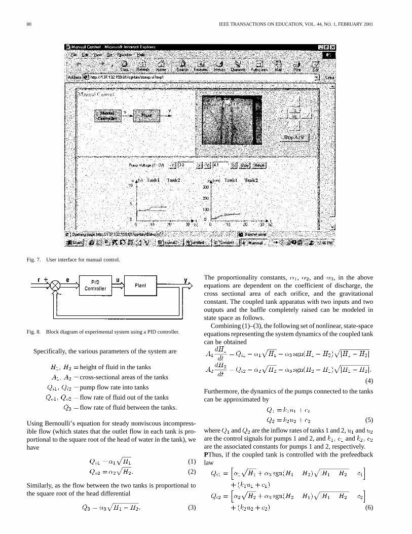
Fig. 7. User interface for manual control.
Fig. 8. Block diagram of experimental system using a PID controller.
Specifically, the various parameters of the system are
height of fluid in the tanks
cross-sectional areas of the tanks
pump flow rate into tanks
flow rate of fluid out of the tanks
flow rate of fluid between the tanks
Using Bernoulli’s equation for steady nonviscous incompress-ible flow (which states that the outlet flow in each tank is pro-portional to the square root of the head of water in the tank), wehave
(1)
(2)
Similarly, as the flow between the two tanks is proportional tothe square root of the head differential
(3)
The proportionality constants, , , and , in the aboveequations are dependent on the coefficient of discharge, thecross sectional area of each orifice, and the gravitationalconstant. The coupled tank apparatus with two inputs and twooutputs and the baffle completely raised can be modeled instate space as follows.
Combining (1)–(3), the following set of nonlinear, state-spaceequations representing the system dynamics of the coupled tankcan be obtained
(4)
Furthermore, the dynamics of the pumps connected to the tankscan be approximated by
(5)
where and are the inflow rates of tanks 1 and 2,andare the control signals for pumps 1 and 2, and andare the associated constants for pumps 1 and 2, respectively.PThus, if the coupled tank is controlled with the prefeedbacklaw
(6)

KO et al.: DEVELOPMENT OF A WEB-BASED LABORATORY FOR CONTROL EXPERIMENTS ON A COUPLED TANK APPARATUS 81
Fig. 9. User interface for PID control.
Fig. 10. Block diagram of experimental system using a state-space controller.
the system can be simplified as
(7)
Note that the above procedure is really a good example of feed-back linearization, as the resulting system dynamics in (7) islinear.
IV. CONTROLLING THE COUPLED TANK APPARATUS
Four different types of controllers which have been imple-mented will now be described.
A. Manual Control
Manual control consists of directly feeding the control inputsgiven by the user to the pumps without the use of any automaticcontroller. The user is expected to adjust the values of the con-trol inputs to achieve the desired water levels in the tanks. Theuser interface for manual control is shown in Fig. 7. Note thatthis can be used to determine critical frequencies of the process,
which will in turn provide useful information for selecting var-ious gains in PID control.
B. PID Control
Fig. 8 shows the block diagram of the overall system, whichcomprises of the PID controller and the plant or coupled tank.Here is the reference input or the set points for the water levelsin the tanks. The continuous time response of a PID controlleris given by
(8)
where is the tracking error, , , and are theproportional, integral, and derivative gains, respectively. In thecoupled tank experiment, the PID controller is realized througha software program and the appropriate discrete-time input is
(9)
While PID control is selected, the user is expected to input thevalues of the two reference inputs (set points) and the valuesof the proportional, integral and differential gains. These valuescan be obtained by tuning the controller using various estab-lished procedures. The user interface for PID control is shownin Fig. 9.
C. Generalized State-Space Control
Fig. 10 shows the block diagram for the control of the coupledtank using a generalized controller modeled in state space. Here,
is the reference input, is the measured output of the coupled-
82 IEEE TRANSACTIONS ON EDUCATION, VOL. 44, NO. 1, FEBRUARY 2001
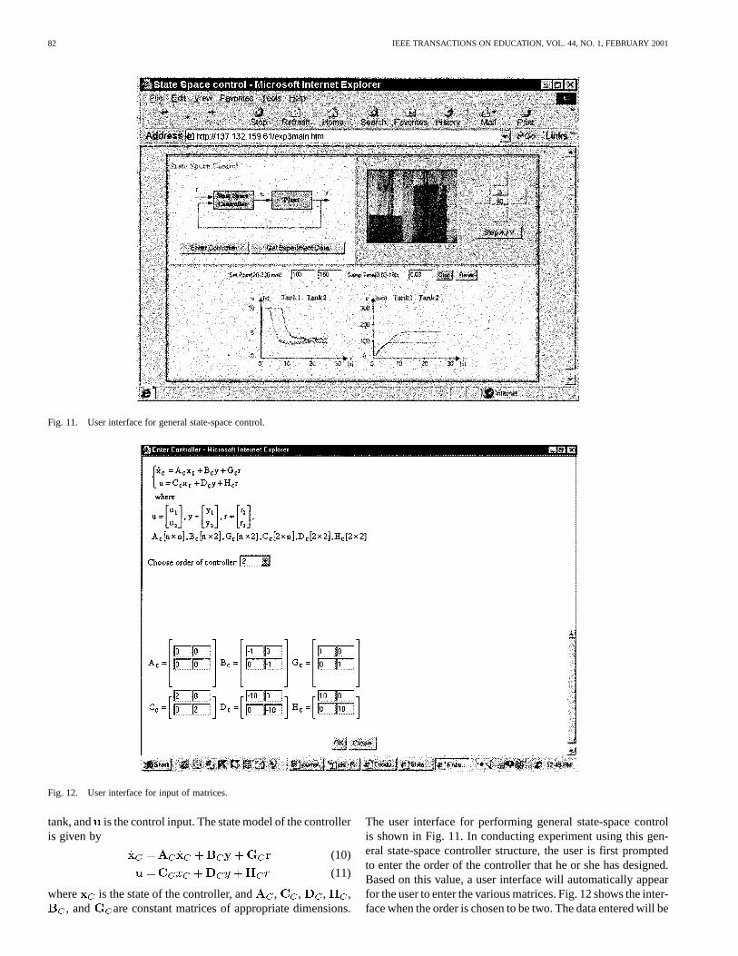
Fig. 11. User interface for general state-space control.
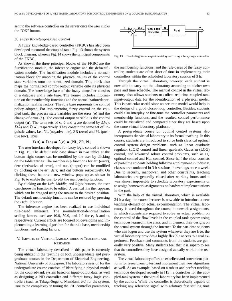
Fig. 12. User interface for input of matrices.
tank, and is the control input. The state model of the controlleris given by
(10)
(11)
where is the state of the controller, and , , , ,, and are constant matrices of appropriate dimensions.
The user interface for performing general state-space controlis shown in Fig. 11. In conducting experiment using this gen-eral state-space controller structure, the user is first promptedto enter the order of the controller that he or she has designed.Based on this value, a user interface will automatically appearfor the user to enter the various matrices. Fig. 12 shows the inter-face when the order is chosen to be two. The data entered will be
KO et al.: DEVELOPMENT OF A WEB-BASED LABORATORY FOR CONTROL EXPERIMENTS ON A COUPLED TANK APPARATUS 83
sent to the software controller on the server once the user clicksthe “OK” button.
D. Fuzzy Knowledge-Based Control
A fuzzy knowledge-based controller (FKBC) has also beendeveloped to control the coupled tank. Fig. 13 shows the systemblock diagram, whereas Fig. 14 shows the principal componentsof the FKBC.
As shown, the three principal blocks of the FKBC are thefuzzification module, the inference engine and the defuzzifi-cation module. The fuzzification module includes a normal-ization block for mapping the physical values of the controlstate variables onto the normalized domain. This block alsomaps the normalized control output variable onto its physicaldomain. The knowledge base of the fuzzy controller consistsof a database and a rule base. The former includes informa-tion on the membership functions and the normalization/denor-malization scaling factors. The rule base represents the controlpolicy adopted. For implementing fuzzy control on the cou-pled tank, the process state variables are the error () and thechange-of-error (). The control output variable is the controloutput ( ). The term sets of , and are denoted by ,
and , respectively. They contain the same set of lin-guistic values, i.e., NL (negative low), ZR (zero) and PL (posi-tive low). Thus
NL, ZR, PL
The user interface developed for fuzzy logic control is shownin Fig. 15. The default rule base shown in two tables at thebottom right corner can be modified by the user by clickingon the table entries. The membership functions for err (error),derr (derivative of error), and out, (output) can be modifiedby clicking on theerr, derr, and out buttons respectively. Onclicking these buttons a new window pops up as shown inFig. 16 to enable the user to edit the membership function.
By clicking on theLeft, Middle,andRightbuttons, the usercan choose the function to be edited. A vertical line then appearswhich can be dragged using the mouse to the desired position.The default membership functions can be restored by pressingtheDefaultbutton.
The inference engine has been realized to use individualrule-based inference. The normalization/denormalizationscaling factors used are 10.0, 50.0, and 1.0 for, and ,respectively. Current efforts are focused on developing and im-plementing a learning algorithm for the rule base, membershipfunctions, and scaling factors.
V. IMPACTS OFVIRTUAL LABORATORIES IN TEACHING AND
RESEARCH
The virtual laboratory described in this paper is currentlybeing utilized in the teaching of both undergraduate and post-graduate courses in the Department of Electrical Engineering,National University of Singapore. The laboratory session for theundergraduate course consists of identifying a physical modelfor the coupled-tank system based on input–output data, as wellas designing a PID controller and different fuzzy logic con-trollers (such as Takagi-Sugeno, Mamdani, etc) for the system.Due to the complexity in tuning the PID controller parameters,
Fig. 13. Block diagram of experimental system using a fuzzy logic controller.
the membership functions, and the rule-bases of the fuzzy con-troller, students are often short of time in implementing theircontrollers within the scheduled laboratory session of 3 h.
Through the virtual laboratory, however, each student isnow able to carry out the laboratory according to his/her ownpace and time schedule. The manual control in the virtual lab-oratory also allows students to collect real-time coupled-tankinput–output data for the identification of a physical model.This is particular useful since an accurate model would help inthe design of a good closed-loop controller. Besides, studentscould also interplay or fine-tune the controller parameters andmembership functions, and the resulted control performancecould be visualized and compared since they are based uponthe same virtual laboratory platform.
A postgraduate course on optimal control systems alsoincorporates the virtual laboratory in its formal teaching. In thiscourse, students are introduced to solve both classical optimalcontrol system design problems, such as linear quadraticregulator (LQR) control and linear quadratic Gaussian (LQG)control, and advanced robust control problems, such as Hoptimal control and H control. Since half the class consistsof part-time students holding full-time employment in industry,classes are conducted in 3-h sessions in evenings once a week.Due to security, manpower, and other constraints, teachinglaboratories are generally closed after working hours and itwas almost impossible to schedule laboratory experiments orto assign homework assignments on hardware implementationsin the past.
With the help of the virtual laboratory, which is available24 h a day, the course lecturer is now able to introduce a newteaching element on actual experimentation. The virtual labo-ratory is used throughout the course homework assignments,in which students are required to solve an actual problem onthe control of the flow levels in the coupled-tank system usingtechniques learned in the class, and implement their designs onthe actual system through the Internet. To the part-time studentswho can logon and use the system whenever they are free, thevirtual laboratory provides a highly flexible access to a real ex-periment. Feedback and comments from the students are gen-erally very positive. Many students feel that it is superb to seethat the controllers they have designed actually work in the realsystem.
The virtual laboratory offers an excellent and convenient plat-form for researchers to test and implement their new algorithmsas well. As an example, based on a robust and perfect trackingtechnique developed recently in [13], a controller for the cou-pled-tank system in the virtual laboratory has been implementedby the authors. While the controller is theoretically capable oftracking any reference signal with arbitrary fast settling time

84 IEEE TRANSACTIONS ON EDUCATION, VOL. 44, NO. 1, FEBRUARY 2001
Fig. 14. Principal components of fuzzy knowledge-based controller.
Fig. 15. User interface of fuzzy knowledge-based control.
from any initial condition, it requires in general an infinite gainto guarantee such a performance. With the flexibility of the vir-
tual laboratory, it is simple and easy to tune certain design pa-rameters to meet the control constraints of the physical system

KO et al.: DEVELOPMENT OF A WEB-BASED LABORATORY FOR CONTROL EXPERIMENTS ON A COUPLED TANK APPARATUS 85
Fig. 16. User interface for editing membership functions.
with some tradeoff in the overall performance. The design wasvery successful and the results have been submitted for possiblepublication. Last, it should be emphasized that the virtual lab-oratory enables making performance comparison of differenttechniques very easily and meaningfully, as the various tech-niques are all implemented under the same setting.
VI. CONCLUSION
This paper has described the design and development of aweb-based laboratory experiment on a coupled tank apparatusand discussed its impact from both a teaching and researchpoints of view. New and attractive features, such as the useof video conferencing for providing audio–visual feedback tothe user and the provision for adjustment of the pan/tilt andzoom of the camera capturing the real-time video, have beenincorporated. Strategies that have been implemented includemanual control, PID control, general state-space control, andfuzzy control. Accessible at http://vlab.ee.nus.edu.sg/vlab/con-trol/, the virtual laboratory has been used for the teaching ofundergraduate and postgraduate courses as well as for researchpurposes. In teaching, the possibility of anytime anywhereaccess allows undergraduate students who are not able tofinish the actual experiment to be able to continue to workon the subject after the formal laboratory session on theirown time through the Internet. For part-time postgraduatestudents, the system solves security and manpower problemsassociated with the operation of teaching laboratories in theevening. The virtual laboratory provides the course lecturer
with the possibility to use a real couple-tank apparatus as aprincipal teaching tool for homework assignments for the firsttime. In research, the system has the advantage that importantparameters can be remotely tuned easily. Also, performancecomparison with different techniques can be obtained veryeasily and meaningfully, as the various techniques are allimplemented under the same setting.
REFERENCES
[1] C. C. Ko, B. M. Chen, S. H. Chen, V. Ramakrishnan, R. Chen, S. Y. Hu,and Y. Zhuang, “A large scale web-based virtual oscilloscope laboratoryexperiment,”Inst. Elect. Eng Eng. Sci. Educ. J., vol. 9, no. 2, pp. 69–76,2000.
[2] M. Shor and A. Bhandari, “Access to an instructional control laboratoryexperiment through the World Wide Web,” inProc. 1998 Amer. Contr.Conf., Philadelphia, PA, 1998, pp. 1319–1325.
[3] M. Shaheen, K. A. Loparo, and M. R. Buchner, “Remote laboratoryexperimentation,” inProc. 1998 Amer. Contr. Conf., Philadelphia, PA,1998, pp. 1326–1329.
[4] “Web-based virtual laboratory, Nat. Univ. Singapore,”,http://vlab.ee.nus.edu.sg/vlab.
[5] S. H. Chen, R. Chen, V. Ramakrishnan, S. Y. Hu, Y. Zhuang, C. C. Ko,and B. M. Chen, “Development of remote laboratory experimentationthrough internet,” inProc. 1999 IEEE Hong Kong Symp. Robot. Contr.,Hong Kong, July 1999, pp. 756–760.
[6] LabView, User Manual: National Instruments, 1998.[7] Coupled Tank Control Apparatus,Model: PP-100, Operator and Service
Manual. Singapore: Kent Ridge Instruments, 1999.[8] Windows NetMeeting 3.0 Help: Microsoft Corporation, 1999.[9] RealServer G2 Help: RealNetworks, 1999.
[10] NetShow 3.0 Documentation: Microsoft Corporation, 1999.[11] “Home page of NUSNET-III,”, http://www.cc.nus.edu.sg/.[12] Window NetMeeting Resource Kit: Microsoft Corporation, 1999.[13] B. M. Chen,Robust and H Control. New York: Springer-Verlag,
2000.
86 IEEE TRANSACTIONS ON EDUCATION, VOL. 44, NO. 1, FEBRUARY 2001
C. C. Ko (M’82–SM’93) received the B.Sc. (1st Class Honors) and Ph.D. de-grees in electrical engineering from Loughborough University of Technology,U.K.
In 1982, he joined the Department of Electrical Engineering, National Uni-versity of Singapore, where he is presently an Associate Professor and DeputyHead (Research) of the Department. His current research interests include dig-ital signal processing, adaptive arrays and mobile communications and he haswritten more than 150 technical publications in these areas.
Dr. Ko has served as an Associate Editor of the IEEE TRANSACTIONS ON
SIGNAL PROCESSING.
Ben M. Chen (S’89–M’92) was born in Fuqing, Fujian, China, on November25, 1963. He received the B.S. degree in mathematics and computer sciencefrom Amoy University, Xiamen, China, in 1983, M.S. degree in electrical en-gineering from Gonzaga University, Spokane, Washington, in 1988, and Ph.D.degree in electrical and computer engineering from Washington State Univer-sity, Pullman, WA, in 1991.
He was a Software Engineer from 1983 to 1986 in the South-China Com-puter Corporation, China, and was a Postdoctoral Associate from 1991 to 1992at Washington State University. He was with the Department of Electrical En-gineering, State University of New York at Stony Brook, from 1992 to 1993,as an Assistant Professor. Since August 1993, he has been with Electrical Engi-neering Department, the National University of Singapore, where he is currentlyan Associate Professor. His current research interests are in linear control andsystem theory, control applications, development of internet-based virtual labo-ratories and internet security systems. He is the author of the books,Robust andH-infinity Control (London: Springer, 2000), andH-infinity Control and Its Ap-plications(London: Springer, 1998), and coauthor of the books,Loop TransferRecovery: Analysis and Design(London: Springer, 1993),H2 Optimal Control(London: Prentice Hall, 1995), andBasic Circuit Analysis(Singapore: PrenticeHall, 1st Ed., 1996; 2nd Ed., 1998).
Dr. Chen was an Associate Editor in 1997–1998 on the Conference EditorialBoard of IEEE Control Systems Society. He currently serves as an AssociateEditor of IEEE TRANSACTIONS ONAUTOMATIC CONTROL.
Jianping Chen was born in Fujian, China in 1971. He received the B.Eng. de-gree from Shanghai Jiaotong University in 1993 and M.Eng degree from Xi-amen University in 1999 respectively, both in control theory. From 1993 to1996, he researched on communication engineering in South-Cube High-TechCo. Ltd, Xiamen.
From January 1998 to June 1999, he researched on intelligent control androbotics in the State Key Laboratory of Intelligent Science and System,which is located in the Computer Science Department of Tsinghua University. His current research interests include network security and intelligent control.
Yuan Zhuang was born in Anhui, China, in 1975. He received the B.Eng. de-gree in electrical engineering from Zhejiang University, China, in 1997. Since1998, he had been pursuing the M.Eng. degree at in the National University ofSingapore.
His current research interest is remote instrument control, distributed systemapplication and web technology development.
Kay Chen Tan (S’95–M’99) received the B.Eng. (First-class honors) and Ph.D.degrees in electrical and electronic engineering from the University of Glasgow,U.K., in 1994 and 1997, respectively.
He was with the Centre for Systems and Control (CSC) and the EvolutionaryComputing Group at Glasgow before joining the Department of Electrical andComputer Engineering in National University of Singapore (NUS) as an As-sistant Professor in 1997. He has published more than 30 technical papers andserved as an IPC Member for many international conferences. His research inter-ests include evolutionary computation, multiobjective optimization, intelligentcontrol, and design automation.