development of a vhf/uhf and s-band communication system for cubesats
TRANSCRIPT

Small Satellite System Development
in the Space Science and Engineering
Laboratory
Montana State University, Department of Physics, 2011 Solar Physics REU
August 3, 2011
Mentors:
Larry Springer, Keith Mashburn, Ehson Mosleh
Nathan Fite
Advisor: Dr. David Klumpar

Overview
• POES 17
• RAMPART CubeSat
• FIREBIRD A/B CubeSats
RAMPART
2 POES 17
(http://www.scottchurchdirect.com/global-
warming.aspx/troposphere-temperature-trends-pt1)
FIREBIRD
Mission
Patch

Acronyms and Terminology
• AUT – Antenna Under Test
• BW – Bandwidth
• C&DH – Command and Data Handling
• CDMA – Code Division Multiple Access
• CPW – Coplanar Waveguide
• CTE – Coefficient of Thermal Expansion
• DL - Downlink
• DUT – Device Under Test
• EIRP – Effective Isotropic Radiated Power
• EPS – Electrical Power System
• FSPL – Free Space Path Loss
• Gr – Receive Antenna Gain
• Gt – Transmit Antenna Gain
•GNSS – Guidance and Navigation
Satellite System
•GPS – Global Positioning System
•HPBW – Half Power Beam width
•Pa – Power Arriving at Antenna
•PCB – Printed Circuit Board
•PPOD – Poly Picosat Orbital Deployer
•RF – Radio Frequency
•RHCP – Right Hand Circular
Polarization
•SDR – Software Defined Radio
•SNA – Scalar Network Analyzer
•SNR – Signal-to-Noise-Ratio
•U – Unit (10cm x 10cm x 10cm)
•UL - Uplink
•VNA – Vector Network Analyzer
•VSWR – Voltage Standing Wave Ratio
3

POES 17
4
• Polar-Orbiting Environmental Satellites
• Size: 4m x 2m
• Weight: 2230kg
• NOAA Satellite
• Spin Stabilized
• Similar Data to E1P, built by MSU SSEL
• Template for E1P Data
• Pertinent Data: – 4 Telescopes
• 2 Electron Telescopes of 3 channels each
• 2 Proton Telescopes of 6 channels each
– FoLat (Geo-Magnetic Latitude)
– Pitch Angles (w/ respect to velocity vector)
POES 17
(http://www.scottchurchdirect.com/global-
warming.aspx/troposphere-temperature-trends-pt1)

POES 17, cont’d
5
• Proton Telescopes – Telescope 1 Oriented Along
Velocity Vector
– Telescope 2 Oriented 90˚
from Velocity Vector
• 6 Linear, Circular Silicon Chips
per Telescope
• Proton Channels Info – Channel 1: 30keV to 80keV
– Channel 2: 80keV to 240keV
– Channel 3: 240keV to 800 keV
– Channel 4: 800keV to 2500keV
– Channel 5: 2500keV to 6900keV
– Channel 6: > 6900keV
RAX CubeSat
(Courtesy Sara Spangelo,
Michigan University)

Proton Flux vs FoLat
6

7

RAMPART
(RApid prototyped Microelectromechanical system
and Propulsion and Radiation Test)
8

RAMPART Overview
• Project Began 3Q 2009
• Size:10cm x 10cm x 22cm
• Weight: 3kg
• Work Completed
– Solar Panels
– Structure
• Work Completed at MSU
– Antenna Systems
RAMPART Deployed Configuration
RAMPART Stowed Configuration
9

Involved Entities
10

RAMPART Mission
• Risk Reduction Mission for POPACS
• Flight Qualify a Payload in low
extremities of Van Allen Belts
• Quantify the radiation experienced by
payload
• Get to elliptical orbit from 90+ burns
from an original LEO circular
• 3D printed Structure
11
POPACS Configuration

POPACS Mission
• Release 2kg Tungsten Sphere
• Study the Effects of Drag due to Atmospheric
Expansion as a function of CMEs
• Same Experiments as RAMPART
12

Communications Systems Level Design
•Black Box
•Power
•Modulation
Transmitter
•Impedance Matching
•Impedance Transform
•Lumped Analysis
Transmission Line
•Impedance Matching
•Beamwidth/Gain
•Polarization
•Feed Point
Antenna
13

Communications System
• Transmission Lines
– Impedance: Unmatched cause reflections
– Can not use simple wire to transport signal
– Utilize Microstrip
• Antennas
– Transducers
– Energy Focusers
– Used Dipole Antennas
14
Model of transmission line at microwave frequencies
(Nakar,,
2004) Microstrip Patch Antenna
VHF/UHF Transmission Lines

FIREBIRD (Focused Investigations of Relativistic Electron
Burst Intensity, Range, and Dynamics)
16

FIREBIRD A/B
17
• 2 Satellite Constellation
• Size: 10cm x 10cm x 16cm
• Weight: 2kg
• Designed and Built by the MSU SSEL, University of New Hampshire, The Aerospace Corporation
• Microburst Electron Precipitation in Radiation Belt Dynamics – What is the spatial scale size of an individual burst?
– What is the energy dependence of an individual burst?
– How much total electron loss do bursts produce globally
• Work To-Date – FIREBIRD GNSS Unit
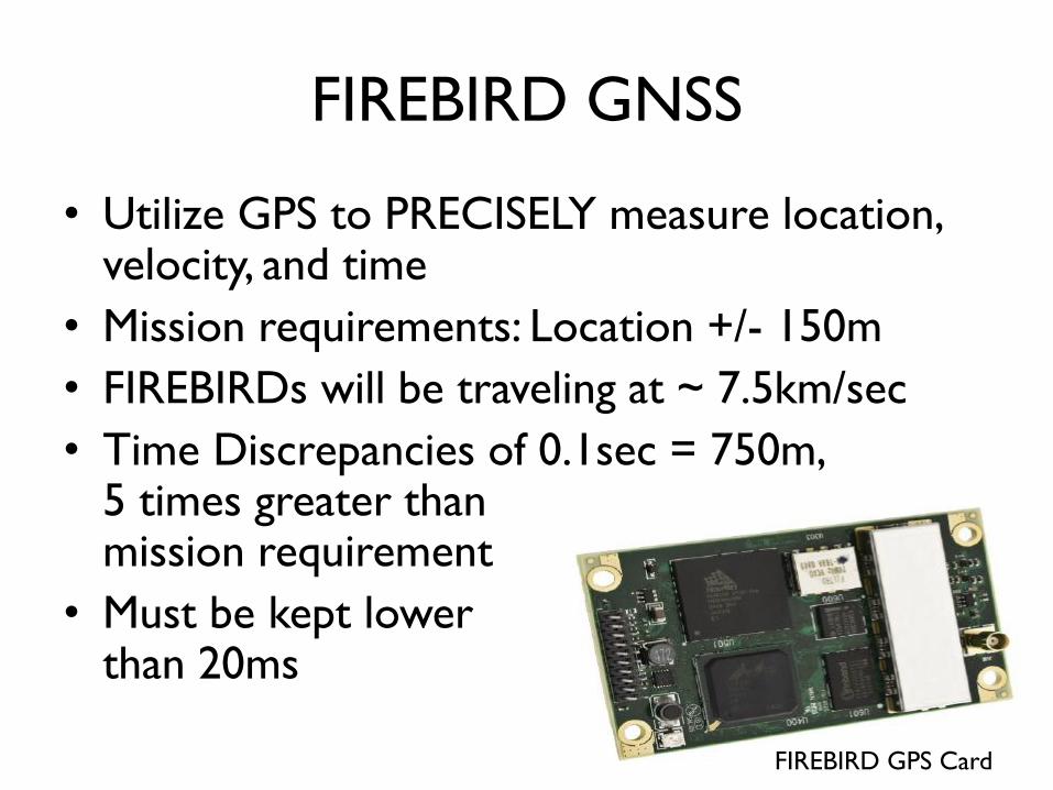
FIREBIRD GNSS
• Utilize GPS to PRECISELY measure location, velocity, and time
• Mission requirements: Location +/- 150m
• FIREBIRDs will be traveling at ~ 7.5km/sec
• Time Discrepancies of 0.1sec = 750m, 5 times greater than mission requirement
• Must be kept lower than 20ms
18 FIREBIRD GPS Card

GPS Constellation
• GPS Constellation consists of 24 satellites
(21 used and 3 backups)
• Height of 20,200km above MSL in 6 orbital
planes
19 Block IIR GPS Satellite
GPS Constellation in
Orbital Planes
GPS Signal
• Composed of: – VERY Accurate GPS Satellite Ephemerides
– VERY Accurate Rubidium Time Standards
– GPS Satellite Health Information
– Error Correction Information
• GPS created by USA DoD – Wanted it unJammable
– Needed to determine how to discern different GPS satellites
• Signals Utilize CDMA (Gold Code) – FHSS Signal, hopping every 1 millisec
– 21023 or 8.99 ∗ 10307 different channels
20

Pseudorange Determination
• GPS Receiver must have 4 GPS satellites’
pseudoranges for acquisition
• 𝑅𝑟𝑠 = 𝜌𝑟
𝑠 𝑡𝑟 − 𝑡𝑠 − 𝛿𝑡𝑟 − 𝛿𝑡𝑠 𝑐 + 𝛿𝑖𝑜𝑛 +𝛿𝑡𝑟𝑜 + 𝛿𝑡𝑖𝑑𝑒 + 𝛿𝑚𝑢𝑙 + 𝛿𝑟𝑒𝑙 + 휀
• 𝜌𝑟𝑠 𝑡𝑟 , 𝑡𝑠 = (∆𝑥)2+(∆𝑦)2+(∆𝑧)2
21
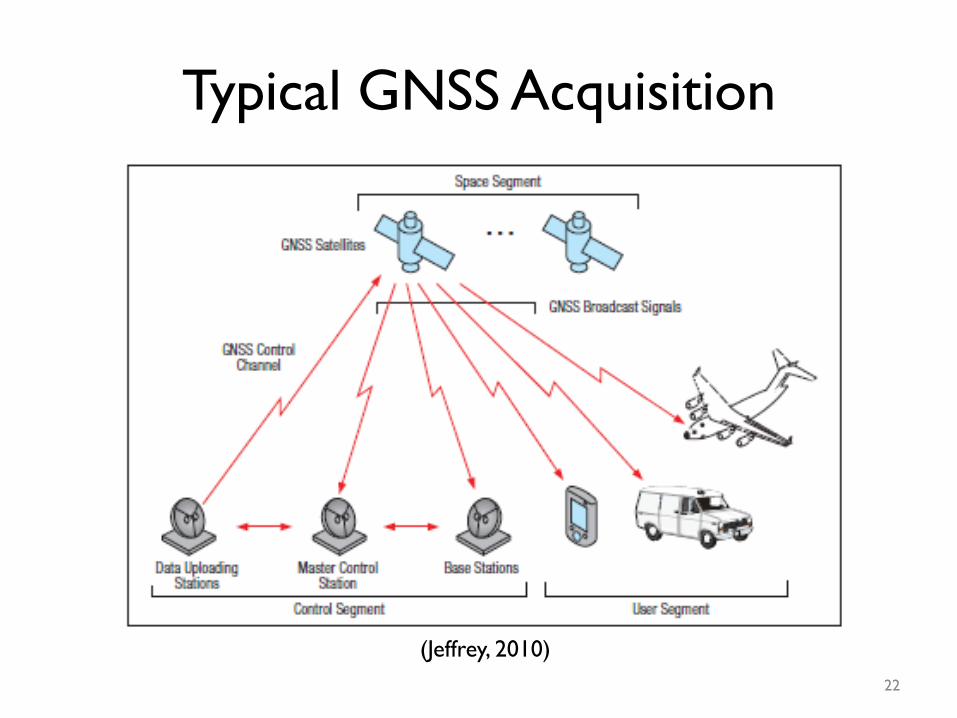
Typical GNSS Acquisition
22
(Jeffrey, 2010)

My Role in FIREBIRD GPS
• Understand Models used and their utilization
• Understand Time Algorithms
• Identify Optimal Command and Log Sets of
the GPS Card with limited data resources
– 196 Logs
– 84 Commands
23

GPS Testing
24
GPS Sensitivity Testing Setup

GPS Testing
• Tested
– Receiver Sensitivity
• Data Sheet: -122dBm
• Empirical: -114dBm
– Acquisition Times
• TTFF Warm ~ 1.5 minutes
• TTFF Cold ~12.5 minutes
– Data Outputs
25
GPS Terminal Window
GPS Sensitivity Testing Setup

GPS Data Rates
• 1Mbps data rate downlink per GPS satellite into FIREBIRD GPS Receiver – ~5% of this data is sent to GPS
Bus to be stored
• Bottleneck caused by limited capabilities of Small Satellites
• Can cause problems later with downlinking to ground station – Ground Station downlink is
19.2kbps
– ~ 10minutes per pass
– ~ 1 pass to download 1 day of GPS data
26
GPS
Receiver
1Mbps
Stuff
C&DH
SD Card
9.6kbps
9.6kbps
9.6kbps

References • Chen, L, Ong, C, Neo, C, Varadan, V.V., & Varadan, V.K. (2004). Microwave electronics: measurement and
materials characterization. England: John Wiley & Sons.
• ETB. (2009). Thermal expansion metals. Retrieved from http://www.engineeringtoolbox.com/thermal-
expansion-metals-d_859.html.
• Franco, S. (2002). Design with operational amplifiers and analog integrated circuits. New York, New York:
McGraw-Hill.
• Garg, R, Bhartia, P, Bahl, I, & Ittipiboon, A. (2004).Microwave antenna design handbook. Norwood, MA: Artech
House, Inc.
• Islam, M, Tuncer, E, & Neikirk, D. (1994). Accurate quasi-static model for schottky-contacted voltgae
controlled coplanar waveguide phase shifters.Electronics Letters, 30. Retrieved from
http://weewave.mer.utexas.edu/MED_files/MED_research/CPW_stuff/R_C_CPW.html
• Jeffrey, C. (2010). An introduction to gnss. Calgary, Canada. Novatel, Inc.
• Kraus, J. (1986). Radio astrononmy. Powell, OH: Cygnus-Quasar Books.
• Kraus, J., & Marhefka, R. (2003). Antennas for all applications. Singapore: McGraw-Hill.
• Nakar, P. (2004). Design of a compact microstrip patch antenna for use in wireless/cellular devices. Unpublished
manuscript, Department of Electrical and Computer Engineering, Florida State University, Tallahassee,
Florida. Retrieved from http://etd.lib.fsu.edu/theses/available/etd-04102004-143656/
• Nugent, R, Munakata, R, Chin, A, Coehlo, R, & Puig-Suari, J. (2008). The cubesat: the picosatellite standard for
research and education. American Institute of Aeronautics and Astronautics,
• Pozar, D. (1998). Microwave engineering. New York, New York: John Wiley and Sons.
• Simons, R. (2001). Coplanar waveguide circuits, components, and systems. New York, New York: John Wiley and
Sons.
• Wadell, B. (1991). Transmission line design handbook. Ann Arbor, MI: Artech House.
• Wolff, E., & Kaul, R. (1988). Microwave engineering and systems applications. New York, New York: John Wiley
& Sons. 27

Thank You
Questions?
Acknowledgments:
SSEL Small Satellite Team
REU Faculty Members
National Science Foundation
28

Transmission Lines
• Max Power Transfer
– Improper impedance
match yields reflections
• Impedance
• Skin Depth(𝛿)
– AC travels along the surface of metallic materials
–
– 3 Skin Depths ~ 95% Transmission
Model of transmission line at microwave frequencies
Coaxial cable
29

Antenna
• Reciprocity – Same for Transmit and Receive
• Transducer – Converts Electrical Energy to EM Energy
– Works inversely for Receiving Electrical Signal
• Impedance Matcher – Converting 50𝛺 to 377𝛺
• Radiation – Produced by Interruption of Current Flow
• Antenna Gain – Not Amplifier
– Focus Energy
– All Antennas are Dipole
• Antenna Environment – Environmentally Dependent
Block diagram of VHF/UHF Transmission Lines
Impedance of free space
30

Satellite Communications Principles
• To communicate satellites must achieve an acceptable SNR according to Friis Equation
• Four Components:
• To Improve the ratio, you can alter: – Transmit Power
– Satellite Antenna
– Ground Station Antenna
– Bandwidth
– System Temperature
31

Microstrip • What is Microstrip?
– Two conducting plates of opposite polarization with a dielectric media between them
• Physical Size determines intrinsic characteristics – W (or L) = λo/2 – Since ϵ ≠ 1,
• Magnetic fields radiate through substrate
http://mwrf.com/files/30/17725/Figure_02.jpg (Nakar,, 2004)
Substrate Characteristics
Material Rogers 4003C
f 2.4015 GHz
ϵ 3.5
h 0.090”
t 0.0028” (2oz)
λo 4.9”
Wground 2.17”
λ (λ/4) 2.6” (0.65”)
𝛿 0.000052”
32

Coplanar Waveguide (CPW)
http://www.microwaves101.com/encyclopedia/coplanarwaveguide.cfm
• What is Coplanar Waveguide?
– Coplanar transmission line with a center
conductor, surrounded by ground plane with
separation between the two
– Essentially, Coplanar Coaxial Cable
http://weewave.mer.utexas.edu/MED_files/MED_research/CPW_stuff/
R_C_CPW.html
33