development of a specification for low cracking …
TRANSCRIPT

DEVELOPMENT OF A SPECIFICATION FOR LOW
CRACKING BRIDGE DECK CONCRETE IN
VIRGINIA
Virginia DOT Workshop – Charlottesville, VA
Harikrishnan Nair, Ph.D., P.E, VTRC
Senior Research Scientist
October 4, 2017

Presentation Outline
• INTRODUCTION
• RESEARCH
• SPECIFICATION DEVELOPMENT
• IMPLEMENTATION

INTRODUCTION
Deck Cracking Problem
• Cracks can result from excessive loading, environmental
conditions, chemical reactions, construction or design
errors.
• Cracks act as a pathway for water and aggressive
chemical ions to penetrate concrete and enable its
deterioration.
3

INTRODUCTION
4
Classification of Cracks (TRB Circular,E-C107)
Type of Cracking Time of Appearance
Plastic Shrinkage 30 min to 6 h
Plastic settlement 10 min to 3 h
Thermal expansion
and contraction
1 day to 2–3 weeks
Drying shrinkage Weeks to months

Deck Cracking Problem
5
Drying shrinkage cracks – may occur weeks to
months after pour.

Deck Cracking Problem
6
Difficult to penetrate cracks < 0.1 mm wide.
Cracks with a width over 0.20 mm can be and should be sealed
Chloride diffusion in cracked concrete
Corrosion Resistant Rebars

RESEARCH
7
To investigate the effectiveness of reducing drying
shrinkage in VDOT concrete mixes using the following:
• Normal weight concrete with Shrinkage Reducing
Admixture (SRA)
• Lightweight (LW) concrete with LW coarse aggregate
• Shrinkage compensating concrete

888SRAs function by reducing capillary tension of pore water
Typically shrinkage reduction achieved is between 35–45%
Potential Crack
SRA: How it works

VDOT Use of Lightweight Concrete Bridge
Deck
9
No Transverse Crack (Continuous two
span bridge on Steel Beams)
(After 33 Years
Route 60 over Maury River
After 30 Years
Skew, no cracks
Route 629 over Cowpasture River

Shrinkage Compensating Concrete
10
Ref: P.K. Mehta and P.J.M. Monteiro, Concrete: Microstructure, Properties, and Materials

METHODS
11
No.
Route or Bridge No./Name
Length
(ft)
Width
(ft)
No. of
Spans
Type of Beam
Support
Skew
Angle
(Degrees)
NWC with SRA
Northern Virginia District (I-95 Express Lanes)
1 B607 (Telegraph Road) 313 40 2 Steel 19
2 B609 (GHS Ramp) 448.3 30 2 Steel 0 (curved)
3 B603 (JHS Ramp) 541 30 3 Steel 0 (curved)
4 B602 (Ramp) 558 30 3 Steel 0 (curved)
5 B601 (Ramp) 964 30 9 Concrete (1
span)/Steel
0 (curved)
Staunton District
6 Route 633 Covington 340 26 3 Steel 0
7 Route 1421 Linville Creek 260 29.67 4 Prestressed concrete
box beams
15
8 Route 250 Ramseys Draft 65 40 1 Prestressed concrete
box beams
30
Fredericksburg District
9 Route 600 Herring Creek 99 40 1 Steel 17
LWC
10 Route 657, Senseny Road,
Winchester/ Staunton
249 32 4 Steel 0
11 Route 128, Chandlers Mountain
Road, Lynchburg/Lynchburg
264 36 4 Steel 0
12 Route 15, Opal/Culpeper 256 28 2 Lightweight
concrete beams
27
13 Route 49, The Falls Road, Crewe/
Richmond
175 42 3 Steel 0
14 Route 646, Aden Road,
Nokesville/Northern Virginia
167 32 3 Prestressed concrete
slab
0
15 Route 3, Piankatank River,
Mathews County/Fredericksburg
4186 28 30 Steel 0
16 I-95 HOV Lane,
Stafford/Northern Virginia
159 48 1 Steel 0
SC
17 Route 613/South Fork/ Staunton 320 28 4 Prestressed concrete
box beams
0
1
Details of Bridges That Used SRA, LWC, and SC

METHODS
12
• Trial batches were conducted for the proposed mix
designs.
• Bridge deck placement details (Concrete temperature, air
temperature, relative humidity and wind speed) were
documented.
• Concretes were tested for fresh and hardened
properties.
• Decks were wet cured for 7 days followed by curing
compound.
• Crack survey’s (length, width, location) were conducted
at different intervals.

Concrete Mix Designs for All Bridges (per
cubic yard)
13
Bridge
Cement
(lb)
Fly Ash (lb) Slag (lb)
Total
Cementitious
Content (lb)
Water
(lb) w/c
NWC with SRA
I-95 Express
Lanes
300 - 300 600 (SRA 1) 271 0.45
Route 633 464 116 - 580 (SRA 2) 262 0.45
Route 1421 325 - 325 650 (SRA 2) 260 0.40
Route 250 480 120 - 600 (SRA 3) 262 0.44
Route 600 480 120 - 600 (SRA 2) 258 0.43
LWC
Route 657 529 176 - 705 267 0.38
Route 128 318 - 317 635 286 0.45
Route 15 330 - 330 660 292 0.44
Route 49 525 171 - 696 313 0.45
Route 646 540 135 - 675 292 0.43
Route 3 508 127 - 635 286 0.45
I-95 HOV Lane 330 - 330 660 292 0.44
SC Concrete
Route 613 572 143 - 715 349 0.48

Trial Batch Results
14
• Acceptable Compressive strength (VDOT Spec: 28 day min
4000 psi)
• Very low permeability – Below 1000 coulombs
(VDOT Spec: 28 day max 2500 Coulombs )
• Excellent Freeze Thaw Durability
SRA (producer 3) reduced the air content
-Higher dosage of air entraining agent
was required
Reduction in shrinkage with use of SRA ranged from 10 – 58%

Placement and Fresh Concrete properties
15
VDOT spec: Range of slump: 2-4 in, Air content: 5-8%
With high-range water–reducing admixture: slump: 2-7 in, Air
content: 5-9%
NWC with SRA
• In most cases concrete mixture was placed by pumping.
• Slump ranged from 2.6 to 6 in and Air content 5.0 to 7.8%
• Paste content (total volume of cementitious material and
water) close to 27%
• The concrete evaporation rates were very low (less than 0.1
lb/ft2/hr) in all projects

Placement and Fresh Concrete properties
16
Lightweight Concrete
• unit weight of the LWC ranged from 114.2 to 120.9 lb/ft3
• In most cases concrete mixture was placed by pumping.
• Average slumps ranged from 4 to 8 inches, and air content
ranged from 5.5% to 8.0%.
• The concrete evaporation rates were very low
Shrinkage compensating concrete
• Hydration stabilizer was used to control the slump loss
• All fresh concrete properties and the evaporation rate met
the VDOT specification

Hardened Concrete Properties
17
Compressive Strength and Permeability

18
28-day Length Change and Elastic Modulus
Hardened Concrete Properties

Shrinkage Results –Lightweight Concrete
(2012 Projects)
19
Cementitious content: 635 lb/yd^3)
Cementitious content: 660 lb/yd^3)
Cementitious content: 705 lb/yd^3)

Crack Survey: NWC with SRA
20
5/2/2018 205/2/2018 20
Route or Bridge
No.
Length
of Bridge
No. of Cracks: Length (ft)
and Width (mm)
Age at Time
of Survey
(months)
Crack
Density
(ft/ft2)
B607 (Telegraph
Road)
313 ft 1 crack: 36 ft (0.2 mm) 15 0.0028
B609 (GHS Ramp) 448 ft 4 cracks: 3 ft (0.25 mm),15 ft
(0.2 mm), 9 ft (0.3 mm),1 ft
(0.25 mm)
7 0.0020
B603 (JHS Ramp) 542 ft No cracks 14 0.0
B602 (Ramp) 558 ft 1 crack: 7 ft (0.2 mm) 13 0.0004
B601 (Ramp) 964 ft 20 short cracks: Average
length: 4-5 ft
5 0.0049
Route 1421 260 ft 3 transverse cracks over the
piers
14 0.0115
Route 250 65 ft No cracks 9 0.0
Route 600 99 ft 5 short longitudinal cracks at
abutments
9 0.0062
Route 633 340 ft Several cracks 19 0.1853

Crack Survey: NWC with SRARte. 633 Staunton District (19 months)
21Did not follow placement sequence (C&D combined)
AB C DE
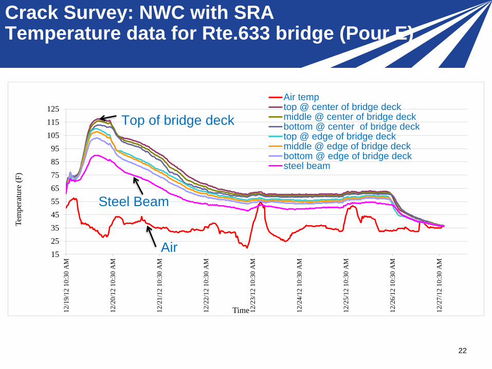
Crack Survey: NWC with SRATemperature data for Rte.633 bridge (Pour E)
22
15
25
35
45
55
65
75
85
95
105
115
125
12
/19
/12
10:3
0 A
M
12
/20
/12
10:3
0 A
M
12
/21
/12
10:3
0 A
M
12
/22
/12
10:3
0 A
M
12
/23
/12
10:3
0 A
M
12
/24
/12
10:3
0 A
M
12
/25
/12
10:3
0 A
M
12
/26
/12
10:3
0 A
M
12
/27
/12
10:3
0 A
M
Tem
per
ature
(F
)
Time
Air temptop @ center of bridge deckmiddle @ center of bridge deckbottom @ center of bridge decktop @ edge of bridge deckmiddle @ edge of bridge deckbottom @ edge of bridge decksteel beam
Steel Beam
Top of bridge deck
Air
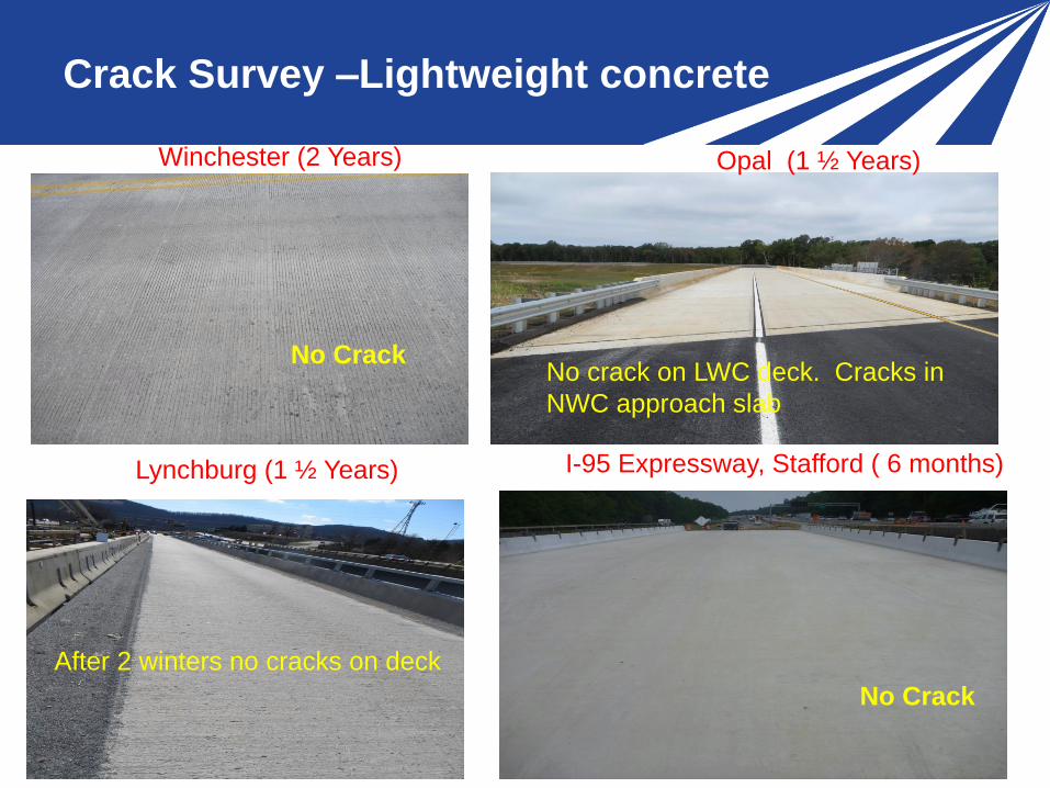
Crack Survey –Lightweight concrete
235/2/2018 235/2/2018 23
Winchester (2 Years) Opal (1 ½ Years)
No crack on LWC deck. Cracks in
NWC approach slab
Lynchburg (1 ½ Years)
After 2 winters no cracks on deck
I-95 Expressway, Stafford ( 6 months)
No Crack
No Crack

Crack Survey –Lightweight concrete
245/2/2018 245/2/2018 24
Mathews County, Fredericksburg (6 Months) Crewe, Richmond (7 Months)
Nokesville, NOVA (10 Months) Nokesville, NOVA (10 Months)
Tight Cracks in Closure Pour
Cracks
No Crack

Crack Survey –Lightweight concrete
25
Crack Survey Plots for Route 646 Nokesville (not to scale)
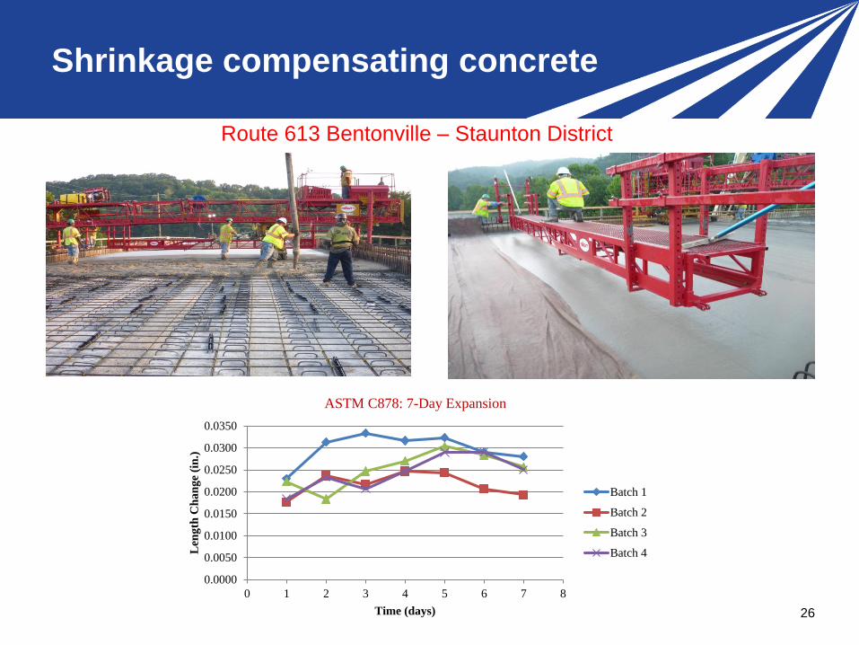
Shrinkage compensating concrete
26
0.0000
0.0050
0.0100
0.0150
0.0200
0.0250
0.0300
0.0350
0 1 2 3 4 5 6 7 8
Len
gth
Ch
an
ge
(in
.)
Time (days)
ASTM C878: 7-Day Expansion
Batch 1
Batch 2
Batch 3
Batch 4
Route 613 Bentonville – Staunton District

CRACK SURVEY: Shrinkage compensating
concrete
27
Longitudinal Cracking
Reflective cracking caused by the differential movement of the
box beams at the keyway
Transverse cracks over the piers were observed
Route 613 Bentonville – Staunton District

CONCLUSIONS
28
•Bridge decks with fewer cracks can be constructed.
•The use of SRA along with low cementitious contents
(600 lb/yd3 maximum) was found to be very effective in
reducing cracks in bridge decks.
•For low cracking decks, the 28-day drying shrinkage
(ASTM C157) should be kept below 350 microstrains.
• Decks with reduced cracks or no cracks can be
successfully placed using LWC with a cementitious content
below 650 lb/yd3 while meeting strength and permeability
requirements.

CONCLUSIONS
29
• The LWCs used in this study had shrinkage values as high as
0.060% and did not crack. This shows the benefits of the
lower elastic modulus, internal curing, and lower coefficient of
thermal expansion of LWC.
• Proper concrete placement, consolidation, and curing are
important factors in achieving crack-free bridge decks.
• Following a proper construction sequence and maintaining a
low temperature differential between concrete and air are
important for reducing cracks in bridge decks.
• A low permeability value for concrete can be achieved by using
fly ash or slag.

30
1. The cementitious materials content shall be less than or
equal to 600 pounds per cubic yard for NWC. The 28-day
drying shrinkage shall be less than or equal to 0.035%
(based on the average of three specimens) when tested in
accordance with ASTM C157.
Specimens shall be moist cured for 7 days prior to testing
for drying shrinkage. A shrinkage reducing admixture shall
be used unless the 28-day drying shrinkage is less than or
equal to 0.035% without the admixture.
2. The cementitious materials content shall be less than or
equal to 650 pounds per cubic yard for LWC and the
maximum fresh density shall be 120 lb/ft3.
SPECIFICATION FOR LOW CRACKING BRIDGE
DECK CONCRETE

Implementation
31
Included in 2016 Road and Bridge specification
http://www.virginiadot.org/business/resources/const/VDO
T_2016_RB_Specs.pdf
SECTION 217—HYDRAULIC CEMENT CONCRETE
217.12—Low Shrinkage Class A4 Modified Concrete

ACKNOWLEDGEMENT
32
VTRC
VDOT Central Office and Districts
FHWA
Industry