development of a side-pot body panel...
TRANSCRIPT
DEVELOPMENT OF A SIDE-POT BODY PANEL FOR A FORMULA
STUDENT RACE CAR
MUHD MUSLIM BIN ABU BAKAR
UNIVERSITI TEKNIKAL MALAYSIA MELAKA
‘I/We* admit that have read this dissertation and in my/our* opinion this dissertation is
satisfactory in the aspect of scope and quality for the bestowal of
Bachelor of Mechanical Engineering (Automotive)’
Tandatangan :……………………
Nama Penyelia I : Mr. Muhd Ridzuan Bin Mansor
Tarikh :……………………
Tandatangan :……………………
Nama Penyelia II : Mr. Mohd Rizal Bin Al-Kahari
Tarikh :……………………
DEVELOPMENT OF A SIDE-POT BODY PANEL FOR A FORMULA STUDENT
RACE CAR
MUHD MUSLIM BIN ABU BAKAR
This report is submitted to the Faculty of Mechanical Engineering
in partial fullfilment of the partial requirement for awarding the
Degree of Mechanical Engineering
(Automotive)
Faculty of Mechanical Engineering
Universiti Teknikal Malaysia Melaka
MAY 2009

“I admit that this report is my own work except the summary and some statement which
is each of them, I already state the source of it”
Signature : ……………………….
Author Name : Muhd Muslim Bin Abu Bakar
Date :………………………...

For my beloved father, beloved mother and beloved person
i
ACKNOWLEDGEMENTS
All praises to Allah the Almighty that by His blessings I have been able to
complete Projek Sarjana Muda (PSM), which the course requirement that in Universiti
Teknikal Malaysia Melaka (UTeM).
Especially, my most gratitude goes to those individuals who have contributed
immeasurable amount of guidance, advice and assistance along the project period; the
first person that really helps in my research is my dedicated supervisor, Mr. Muhd
Ridzuan Mansor, who has supportively guiding and teaching a lot of valuable
knowledge, also for the opportunities he has given me in exposing myself to research
and development environment.
The dedicated staffs in Faculty of Mechanical Engineering and Faculty of
Manufacturing Engineering for the time, their valuable advice and guidance when
solving the problem. The supportive BMCA fellows for lending their hands and giving
continuous support during my project period to achieve the objective of study.
With the full cooperation from the people above, I have successfully achieved the
objectives of this project.

ii
ABSTRACT
The paper presents a conceptual design of side-pot body panel for UTEM
formula style race car. The development process involved two major stages; conceptual
design and structural analysis. In first stage, a side-pot body panel design was selected
and a 3D model of a side-pot body panel was developed using CATIA V5R16 computer
aided design software. Further analysis of a material selection has brought the selection
of Glass Fiber Reinforced Polymer (GFRP) as the side-pot body panel material. The 3D
of a side-pot model will be applied in detailed structural analysis using finite element
analysis; MSC Patran Nastran 2005. In the later stage was the fabrication of side-pot
body panel using wet-lay up process. Thus the discussion and conclusion is made. The
recommendation is suggested to make an improvement in future study.

iii
ABSTRAK
Laporan ini mengetengahkan mengenai konsep rekabentuk “side-pot” untuk
kereta lumba UTeM. Proses pembangunan melibatkan dua factor penting iaitu
rekabentuk konsep dan analisis struktur. Bahagian pertama rekabentuk “side-pot” telah
ditentukan dan model 3D untuk “side-pot” telah dihasilkan menggunakan perisian
CATIA V5R10. Analisis telah dijalankan bagi menentukan jenis bahan dan hasil analisis
mendapati bahan yang sesuai untuk projek ini adalah polimer yang diperkuat dengan
gentian kaca. Analisis struktur “side-pot” telah dilakukan menggunakan perisian MSc
Patran Nastran 2005 untuk menentukan kekuatan pada “side-pot”. Seterusnya, diskusi
dan kesimpulan telah dilakukan. Cadangan penambah baikan untuk pembangunan “side-
pot” telah dicadangkan untuk pembangunan pada masa hadapan.

iv
TABLE OF CONTENT
TITLE PAGE
ACKNOWLEDGEMENTS i
ABSTRACT ii
ABSTRAK iii
TABLE OF CONTENT iv
LIST OF TABLES viii
LIST OF FIGURES ix
LIST OF SYMBOL xi
CHAPTER I INTRODUCTION 1
1.1 Objectives 2
1.2 Problem Statement 2
1.3 Scopes 2
1.4 Benefit of Study 3
CHAPTER II LITERATURE REVIEW 4
2.1 Formula Student Racing Car 4
v
2.2 Society of Automotive Engineers (SAE) 5
2.3 Formula Society of Automotive Engineers (SAE) 6
2.4 Bodywork 7
2.5 Composite 7
2.5.1 Fiber Reinforced 9
2.5.1.1 Glass Fiber 11
2.5.1.2 Carbon Fiber 13
2.5.1.3 Aramid Fiber 13
2.5.1.4 Comparison between Fiber Reinforced 13
2.5.2 Matrix 14
2.5.3 Process 15
CHAPTER III THEORY 16
3.1 Composite Calculation 16
CHAPTER IV RESEARCH METHODOLOGY 18
4.1 Methodology Planning 18
4.2 Project Workflow 19
4.3 Research Method 20
4.4 Design Method 20
4.5 Calculation Method 22
4.6 Analysis Method 23
4.7 Fabrication Method 23
4.7.1 Methodology - Mold Construction 24
vi
4.7.2 Methodology – Final Product 26
4.7.3 Health and Safety 29
CHAPTER V SIDE-POT DESIGN 30
5.1 Concept Design 32
5.1.1 First Concept 32
5.1.2 Second Concept 33
5.1.3 Third Concept 34
5.2 Concept Design Evaluation 34
5.3 Final Design Selection 36
5.4 CAD Design 36
CHAPTER VI CALCULATION 37
6.1 Composite Calculation 37
CHAPTER VII RESULT & DISCUSSION 40
7.1 Finite Element Analysis 40
7.1.1 FEA: Case 1 41
7.1.2 FEA: Case 2 44
7.1.3 FEA: Case 3 47
7.2 Final Product 49
CHAPTER VIII CONCLUSION & RECOMMENDATION 51
8.1 Conclusion 51
vii
8.2 Recommendation 52
REFERENCES 53
APPENDIX A 55
APPENDIX B 56
APPENDIX C 60
viii
LIST OF TABLES
NO TITLE PAGE
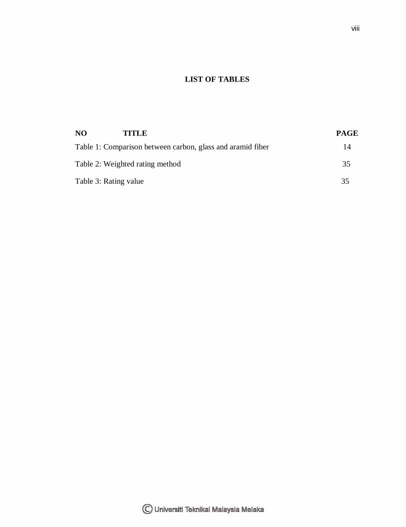
Table 1: Comparison between carbon, glass and aramid fiber 14
Table 2: Weighted rating method 35
Table 3: Rating value 35

ix
LIST OF FIGURES
NO TITLE PAGE
Figure 1: Formula SAE Racing Car (The University of Western Australia, 2006) 4
Figure 2: Formation of composite material using fibers and resin 8
Figure 3: Comparison between conventional materials over composite 8
Figure 4: Continuous fiber composites and short fiber composites (Mallick, 2008) 9
Figure 5: Basic building blocks in fiber-reinforced composites (Mallick, 2008) 10
Figure 6: Common forms of glass fibers (Mallick, 2008) 12
Figure 7: Wet lay-up process (Yuzhairi 2008) 15
Figure 8: Flow chart for overall process of side-pot project 19
Figure 9: Flow chart of concept design generation 21
Figure 10: Flow chart for composite calculation 22
Figure 11: Equipment use in mold construction 24
Figure 12: Side-pot measurement 25
Figure 13: Plywood cutting for side-pot mold surfaces 25
Figure 14: Mold for side-pot body panel 26
Figure 15: Fiberglass woven 26
Figure 16: Fiberglass chopped-strand mat (CSM) 27
Figure 17: Fiberglass was placed on the mold surface 27
Figure 18: Resin with hardener were brush towards fiberglass 28
Figure 19: Side-pot body panel (before trim) 28
x
Figure 20: Final product for side-pot body panel 29
Figure 21: Flow chart on side-pot design 31
Figure 22: First side-pot concept 32
Figure 23: Second side-pot concept 33
Figure 24: Third side-pot concept 34
Figure 25: CAD design for side-pot body panel for right hand side 36
Figure 26: Layer of composite 38
Figure 27: FEA result for side-pot body panel (Stress Tensor) – Outside view 42
Figure 28: FEA result for side-pot body panel (Stress Tensor) –Inside view 42
Figure 29: FEA result for side-pot body panel (Displacement) – Inside view 43
Figure 30: FEA result for side-pot body panel (Displacement) – Outside view 43
Figure 31: FEA result for side-pot body panel (Stress Tensor) – Inside view 44
Figure 32: FEA result for side-pot body panel (Stress Tensor) – Outside view 45
Figure 33: FEA result for side-pot body panel (Displacement) – Inside view 46
Figure 34: FEA result for side-pot body panel (Displacement) – Outside view 46
Figure 35: FEA result for side-pot body panel (Stress Tensor) – Inside view 47
Figure 36: FEA result for side-pot body panel (Displacement) – Outside view 48
Figure 37: FEA result for side-pot body panel (Displacement) – Inside view 48
Figure 39: Final product of side-pot body panel 50
Figure 40: Hole position for joint (red circle), hole (small picture) 50
xi
LIST OF SYMBOL
k = number of ply
a = gravitational acceleration, m/s-2
Q = stiffness matrix
t = thickness of composite ply
E11 = modulus of elasticity
E22 = modulus of elasticity
V12 = poisson ratio

1
CHAPTER 1
1 INTRODUCTION
In recent years, advanced fiber reinforce composite have gradually emerged as a
new class in engineering design of structural component. The composite properties of
high strength and also their high ratio of surface area to weight have made the suitable
candidate for structural applications including aircraft and automobile.
Formula student is a competition where the students have the opportunities to
design, fabricate and also to represent their college to compete with other team. Formula
Student also called Formula Society of Automotive Engineer (FSAE). There are several
important factors in order to produce competitive formula student cars which are the
performance of the car and also the car aesthetic. Society of Automotive Engineer (SAE)
had stated the rules and the standard specification in order to provide a guideline for the
participant.
In Universiti Teknikal Malaysia Melaka, Formula Student is still new. In recent
year, there are several cars for the formula student was build. Even though, the car
specification did not follow the standard for the Formula Society of Automotive
Engineer (FSAE), the car is very competitive. The car bodywork is using the fiberglass
but not required specific justification on the thickness and also the composite calculation
for the composite strength.
2
1.1 Objectives
This thesis is done to design and fabricate the side-pot body panel for a formula
student racing car by using composite material.
1.2 Problem Statement
The goals for this project are to design and fabricate the side-pot by using glass
fibers-reinforced polymer composite. The side-pot is built to the requirements specified
by the Society of Automotive Engineers (SAE). Specifically, the intention is to design,
analyze and fabricate the chassis, as well as designing and constructing a test for the
side-pot. The specifications dictated by Formula SAE are meant to challenge student’s
knowledge, creativity and imagination in designing for a formula SAE car. In the end,
the side-pod had been designed, analyzed and fabricated that meets the students
deliverable deadlines and fundamental design goals.
1.3 Scopes
The basic component for a formula student racing car consist of the frame
chassis, the side-pot, nose, the cockpit and also the space for engine compartment. The
limitation of this thesis is to design a side-pot by using CATIA software and analyze the
design by using the finite element software. The other scopes are to fabricate a side-pot
for a formula student racing car by using a fiber reinforced polymer. Briefly the scopes
are:-
i. Designing the side-pot
ii. Finite element analysis of the design
iii. Side-pot fabrication
3
1.4 Benefit of Study
Formula student is an advantage for a student to learn and gain an experience
during the process of producing a formula student racing car. This study involved both
theoretical and also practical skill. This part of the study also develops the student soft
skill including teamwork, time management and also a problem soft skill. In addition,
the knowledge in manufactured the side-pot is the valuable experience. Research skill
also has gain in order to finish up this project.
4
CHAPTER 2
2 LITERATURE REVIEW
2.1 Formula Student Racing Car
Formula student is a student event who represents the university from the entire
world. Basically, the student design, fabricate a car and compete with a small formula
style race car. The car must satisfy the competition rule and also the safety requirements.
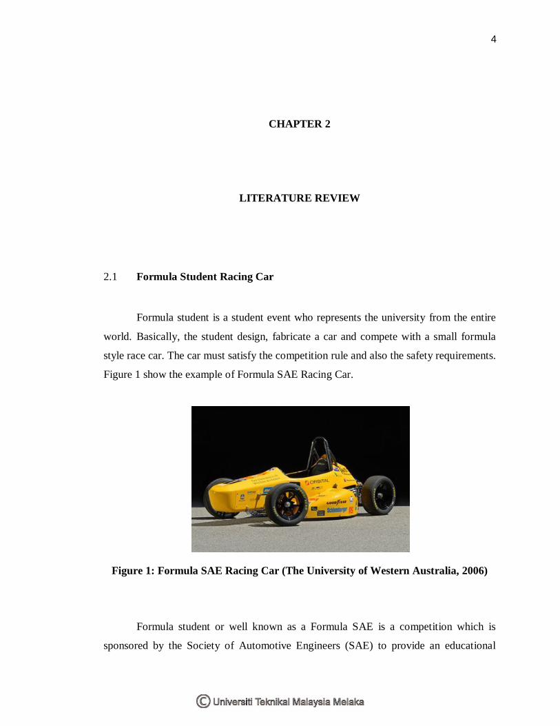
Figure 1 show the example of Formula SAE Racing Car.
Figure 1: Formula SAE Racing Car (The University of Western Australia, 2006)
Formula student or well known as a Formula SAE is a competition which is
sponsored by the Society of Automotive Engineers (SAE) to provide an educational
5
experience for a students and also to expose in project management. Formula SAE
competition give teams the maximum design flexibility and the freedom to express their
creativity and imaginations. Formula SAE competition also gives the students chance to
demonstrate and prove both creativity and engineering skills in comparison with the
teams from other university. All participants must follow the standard car specification
guideline which is providing by Society of Automotive Engineers (refer to Appendix 1).
Society of Automotive Engineers aim was to address a need for the free exchange of
ideas and to develop a standard for those in the emerging automotive industry. This need
was mention by Peter Heldt editorial in The Horseless Age from 1902:
“Now there is a noticeable tendency for automobile manufacturers to follow
certain accepted lines of construction, technical questions constantly arise which seek
solution from the cooperation of the technical men connected with the industry. These
questions could best be dealt with by a technical society. The field of activity for this
society would be the purely technical side of automobiles.” (formula SAE, 2008)
By referring to the Peter Heldt editorial, Formula Society of Automotive
Engineers is the way for Society of Automotive Engineers (SAE) to realizing their
dream.
2.2 Society of Automotive Engineers (SAE)
There were several automobile manufactures in the United States in the early of
1900s. In order to meet their needs for promoting their business and raising public
awareness, they had joined trade groups. Sequentially to expand their individual
technical knowledge base, many of the engineers in the automobile business expressed a
desire to change their ideas among them. (formula SAE, 2008)
Two authors were tireless advocates of the concepts that moving into creation of
Society of Automobile Engineer (SAE) which. The two authors are Peter Heldt of The

6
Horseless Age and Horace Swetland of The Automobile. Horace Swetland is become the
voice of the automobile engineer hence Horace Swetland become original SAE officer.
During meting in 1916, there was a new society representing engineers in all types that
officially establish. The term “automotive” from Greek autos (self), and Latin motivus
(of motion) origins to represent any form of self powered vehicle. In fact of, the Society
of Automobile Engineers became the Society of Automotive Engineers. (formula SAE,
2008)
2.3 Formula Society of Automotive Engineers (SAE)
First race for Formula SAE was held at University of Houston in 1979 which
called SAE Mini-Indy. The cars were made by wood and using the five horsepower
Briggs and Stratton engine to accelerate the car. The University of Texas at El Paso was
the first won which overall participated was thirteen colleges. There were several rules
that should be followed by each university. The rules were about the type of engine and
the overall project cost. University of Texas at Austin was hosted in 1984 for the SAE
Mini-Baja competitions. Dr. Robert Woods, had changed the concept during the
competition at University of Texas at Arlington in 1985. The idea by Dr. Robert Woods
was to make this competition as an activity committee and also gave the student chance
to build a pure racing car. General Motors hosted the competition in 1991, Ford Motor
Co. in 1992, and Chrysler Corp. in 1993. After the 1992 competition, SAE Mini-Indy
competition was changed to Formula Society of Automotive Engineers.

7
2.4 Bodywork
The main objective for car bodywork is to protect the car driver. The purpose for
the composite bodywork is to reduce the weight. The bodywork dimension must exactly
suitable with the frame or chassis structure. The functional of the bodywork design are
lightness, rigidity, a smooth surface, control of airflow and also the aesthetic value of the
car. The method to manufacture the bodywork is very important to achieve perfect
bodywork especially in side-pot fabrication. The fabrication of the side-pot is using the
composite material.
In order to fabricate the side-pot design, the selection of composite is important.
The factors that must be considered are the composite cost, strength and easy in bonding.
In fabricate the side-pot by using the composite material, it necessary to create a mold
first. The mold is important to achieve the good surface finish. The most suitable
composites for the side-pot fabrication were the fiber composite.
2.5 Composite
Composites, as they known today, emerged almost immediately after the
introduction of polymers during the World War II. By 1942, the first applications of
composites involved fiber-reinforced plastics to protect radar equipment. In 1950’s,
composites have been use in aeronautical and aerospace applications, particularly use in
United States (Papathanasiou and Gue, 1997). In 1970’s, the sporting equipment such as
tennis racquets had been manufactured by using the composites material (James et al.
2006). In 1980’s, automotive technology had started to use the composites material. The
first application is for the Corvette rear leaf spring by using the fiber-reinforced
composites (Mallick, 1993).
8
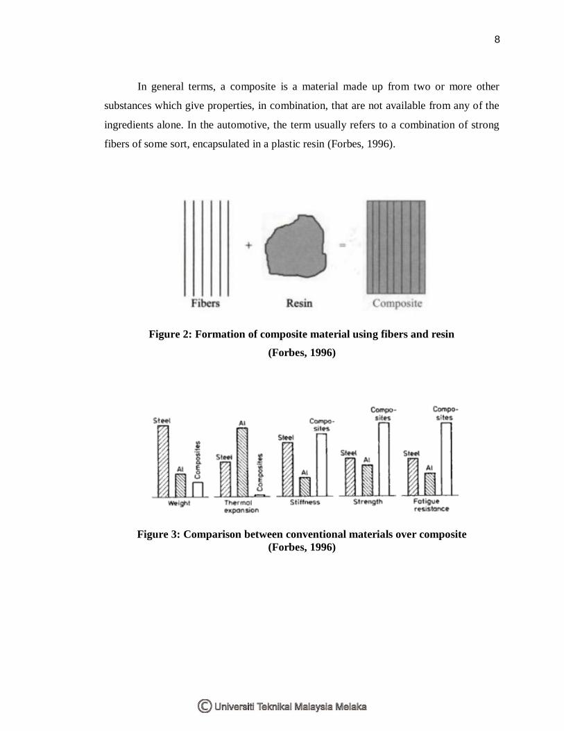
In general terms, a composite is a material made up from two or more other
substances which give properties, in combination, that are not available from any of the
ingredients alone. In the automotive, the term usually refers to a combination of strong
fibers of some sort, encapsulated in a plastic resin (Forbes, 1996).
Figure 2: Formation of composite material using fibers and resin (Forbes, 1996)
Figure 3: Comparison between conventional materials over composite (Forbes, 1996)