development of a rotational meshing actuator for in-home
TRANSCRIPT

Endo et al. Robomech J (2017) 4:4 DOI 10.1186/s40648-016-0072-0
DEVELOPMENT REPORT
Development of a rotational meshing actuator for in-home life support systemsMai Endo, Mitsuru Endo and Takao Kakizaki*
Abstract
For elderly and physically disabled people, support systems that assist their active daily life are as important as appro-priate rehabilitation. We have designed a rotational meshing actuator for a life support system based on a mobile robot. The present paper explains the basic concept of the actuator and its design details. The actuator comprises a motor-controlled active mechanism mated with a passive mechanism. The trident pin on top of the active mecha-nism engages with a similar pin on top of the passive mechanism, transmitting the rotational motion between the mechanisms. The rotation transmission characteristics of the actuator were experimentally investigated using an actuator prototype. Finally, the developed actuator was mounted on a mobile robot, and its practical feasibility was confirmed by a window curtaining experiment.
Keywords: Actuator, Gear, Transmission, Mechanism, Rotation, Robot
© The Author(s) 2017. This article is distributed under the terms of the Creative Commons Attribution 4.0 International License (http://creativecommons.org/licenses/by/4.0/), which permits unrestricted use, distribution, and reproduction in any medium, provided you give appropriate credit to the original author(s) and the source, provide a link to the Creative Commons license, and indicate if changes were made.
BackgroundJapan currently faces a decreasing labor population and an increasing elderly population. The resulting social problems demand immediate and urgent actions by national or local governments [1]. To satisfy these requirements, researchers have developed a variety of robot-based life support systems to care for elderly peo-ple as well as assist with in-home rehabilitation [2–7]. Despite the previous researches on life support systems, the wide variety of people requiring care, especially in their homes, requires further investigation. For example, elderly people and those with slight physical disability require not only appropriate rehabilitation, but also life support systems that assist their active daily life (ADL). Inevitably, daily life activities will be assisted by robot technology (RT) software components and middleware services in future [8]. Similarly, novel mechanical and electronic elements should be developed and integrated into various life support systems for individuals.
Present life support systems can be broadly categorized into several types. The home care system comprises a
mobile robot with a manipulator subsystem. For exam-ple, service robot applications that care for elderly people in their home environments have been experimentally tested and reported [9]. Here a manipulator-type reha-bilitation robot is attached to the wheelchair or other objects by a specially designed docking station (DS). The DS location permits the robot to move within the local environment, and sometimes from one room to another. Chung et al. [10] installed manipulators in a multi-functional indoor-service robot system. The mobile-manipulator-type service robots developed by them were designed to behave as intelligent agents in a real envi-ronment. However, their application area was limited to a public indoor environment, which is more structured than home. Under the assistive mobile manipulator of Jain and Kemp [11], the robot can retrieve objects from and deliver objects to flat surfaces. The developed system was expected to identify many objects because flat planes are commonly orthogonal to gravity in indoor human environments. On the other hand, Sato et al. [12–14] pre-sented a series of researches on the pioneering concept of Robotic Room, which embraces humans and necessary robotic sub-systems in a unique spatial system. For exam-ple, their Robotic Sick Room appliances are equipped with various sensors, a robotic arm, and a network con-necting the sensors and robots for patients’ life support.
Open Access
*Correspondence: [email protected] Mechanical Engineering Department, College of Engineering, Nihon University, 1 Nakagawara, Tokusada, Tamura-machi, Koriyama, Fukushima 963-8642, Japan

Page 2 of 12Endo et al. Robomech J (2017) 4:4
As explained above, various life support systems are expected to be developed in the near future. Therefore, we have been investigating simple systems that can be installed without significantly altering the current living environment. Our first proposal is a simple device that enables object manipulation in daily living environments.
Figure 1 schematizes our REACH (Robotic Enhanced Assistant Co-existing in Home) system, developed for both ADL and rehabilitation. The main components are a multimodal man–machine interface, a system server, and an omnidirectional mobile robot [15]. The system observes the motions of the person requiring care support and decides the necessary assistance. However, the required assistance for people with disabilities has not been suf-ficiently clarified. Therefore, to determine the necessary support, the observed information is compared with a database based on the Brunnstrom stages, which index the progress of a patient’s recovery after a stroke [16].
In this paper, we design actuator mechanisms for a mobile support robot that assists patients in their resi-dential rooms. In general, the necessary life supports include physical operation assistance such as object loca-tion and handling, care tool/appliance adjustment, and utility condition controls. As stated above, most of these requirements may be met by robotic manipulators with multi-degrees of freedom, which are typically employed in industries [17]. On the other hand, because our pro-posed system provides minimum ADL supports to patients with slight disabilities, it mainly employs a single passive motor. Thus, the system can be sufficiently manu-factured even by small/medium companies.
MethodsApplication concept of proposed actuatorFigure 2 schematizes the proposed actuator mounted on a mobile robot in a residential room. The concept of Fig. 2 was inspired by previous studies [12–14]. Designed for simplicity, this example features a simple mobile robot, passive tools installed on existing appliances dis-persed through the room, and a motor mounted on the mobile robot, which delivers the sole power supply.
In developing the proposed system, we stipulated that the mobile robot performs multiple indoor support tasks. However, multi-tasking is not easily achieved by a single robot with restricted functions. Most ADL support tasks require the exertion of adequate and necessary forces and torques. Therefore, in the presented system, we supple-ment the passive mechanism with a simple rotational meshing actuator pair driven by a motor-controlled active mechanism. The passive actuator is connected by a simple mechanical interface to an appropriate tool or end-effector located in the residential room. Although certain limitations cannot be avoided, this design can access any conventional appliances/facilities required by the patient.
For example, an in-plane omnidirectional mobile robot can locate at any position on a flat floor. When connect-ing the active and passive actuator mechanisms, the robot should be appropriately positioned for supporting the patient. Once the actuator pair is loosely connected by meshing, the active mechanism transfers its rotational motion to the passive one, increasing its connectivity to the mechanical tool or end effector. The simple tool or
Support Requirement
Observing State / Condition
Support
Request
Watch
Distinguish TasksDistinguish Tasks
Fig. 1 Concept of the REACH life support system

Page 3 of 12Endo et al. Robomech J (2017) 4:4
end effector might be a rotation-to-translation conver-sion mechanism, such as a pulley with a timing belt. Such tools are useful for curtaining and louvering of windows, or for realizing a simple gripper for object grasping. It should be noted that the robot and end-effector can be tightly connected through the passive latching mecha-nism. Driven by the rotating actuator, the latching mech-anism on the end-effector can grip the robot housing. Having established a tight connection, the robot can trail simple objects across the floor.
The proposed actuator has a simple and mono-func-tional system. Thus, unlike the long reach manipulator equipped in the Robotic Room, it cannot easily perform tasks with multiple degrees of freedom. Furthermore, as shown in Fig. 2, the robot requires an adequate number of sensors because the room is not intelligently struc-tured like the Robotic Room. However, as the necessary power to drive the distributed appliances is supplied by the robot, the appliances require no motors, batteries or controllers, even if additional installation is required. Therefore, the proposed actuator is a potentially use-ful add-on to other conventional systems, providing an effective tool for physical agents.
Rotational meshing actuatorBasic conceptAs explained above, the tool/end effector is driven by a pair of active and passive mechanisms. Hereafter, this active–passive pair is called the rotational meshing
actuator. Furthermore, for simplicity, the active and pas-sive actuator components are called the A-Gear and P-Gear, respectively. Positive clutch and friction clutch are two typical mechanisms of rotation transmission. The friction clutch enables connection with high-speed rotation, but its friction surface should be finished with high accuracy. On the other hand, positive clutches such as the jaw clutch have a simple mechanical structure, but are unsuitable for high-speed operation.
In the present study, the gears should meet the follow-ing specifications; (1) transmittable rotation within cer-tain connecting errors, (2) a simple shape that is easily manufactured, (3) no demand for fast and highly accu-rate rotation, and (4) relatively low torque and speed, which are sufficient for objective tasks. Consequently, we adopted gears with a trident pin structure for their geo-metrical and functional simplicity.
Figure 3 is a schematic of the gears and their nomi-nal meshing configuration. The trident structure is for-mulated by three pins arranged on a cylindrical flange attached to the top of both gears (see Fig. 3a). To acti-vate the meshing gears, the A-Gear (which rotates at constant speed) is moved toward the P-Gear along the mutual rotational axis. Successful gear meshing requires that the A-Gear approaches and locates in an appropri-ate position. This is achieved by locating the P-Gear at its given nominal position. The position data are then modified according to data from sensors mounted on the mobile robot. Under nominal operation, the presented
Curtaining gear
Trash boxgear
Mobile robot
Height adjustment table gear
Height adjustment chair gear
Container gear
Fig. 2 Concept of robot support in a residential room

Page 4 of 12Endo et al. Robomech J (2017) 4:4
meshing actuator is expected to work like a mechanical joint. However, the actuators should successfully mesh within slight positioning tolerances. Therefore, the top of each trident pin is rounded to ensure effective meshing of both gears. In addition, the positioning error between the gears is relaxed by a compliance mechanism installed between the A-Gear and the robot.
Whether the three-pin gear design is the theoretically optimum solution is difficult to determine. For example, although gear meshing is possible in a two-pin design, the required pin diameter is larger than in the three-pin design, and only one meshing pattern is available. Four or more pins would enable a variety of meshing patterns, but would increase the complexity of the meshing. As mentioned above, the trident structure is geometrically and functionally simple.
Basic structure of GearsFigure 4 shows the design parameter and drawing of gear trident pin. As shown in Fig. 4b, the flange diame-ter, pin diameter, and height of the prototype are 59, 16, and 4 mm, respectively. The detail of design process of these drawing is explained later. During nominal mesh-ing, the pin size and arrangement comply with the allow-able clearances between both gears. The trident pin of the A-Gear is photographed in Fig. 5. An initial prototype was made by a compact computerized numerical con-trol machine. Next, a mold was constructed from silicon rubber. Finally, the pin was fabricated from high strength
polyurethane resin. Because position/orientation error cannot be avoided in the A/P gear meshing, we must ensure adequate compliance of one or both gears for safe operation. To this end, we introduce a simple compliance mechanism between the A-Gear and the robot compli-ance system, and between the A-Gear and the robot housing.
Figure 6 schematizes the compliance mechanism of the A-Gear. The mechanism comprises three coaxi-ally arranged flanges interconnected by coil springs. One distal flange is connected to the rotational axis of a motor mounted on the robot; the other distal flange is connected to the trident part, as shown in the figure. Adjacent flanges are loosely connected by six bolts, each wound by a coil spring. The nominal diameter and axial clearances between the bolt and hole are 1 and 25 mm, respectively. Consequently, the radial compliance at the trident potion of the A-Gear is 380 N/m. Here, the nominal spring constant of the coil springs employed in the mechanism is 200 N/m. The weight and dimen-sions of the A-Gear are 100 N and (350 × 60 × 80) mm3, respectively. The A-Gear attached to the robot is driven by a DC servo motor. The P-Gear is not detailed, because (apart from the compliance mechanism) it is structurally identical to the A-Gear. The P-Gear can be connected to various tools in the residential environment, as explained above.
Gear meshing patternsPreliminary experiments on a gear prototype revealed three possible meshing modes for rotational transmis-sion. In the following, we refer to these modes as mode-I, mode- II, and mode III.
The three meshing modes are presented in Fig. 7. In mode-I, the A-Gear and P-Gear mesh almost in the nom-inal position, with little positioning error. The rotation is transferred from the A-Gear to the P-Gear similarly to conventional mechanical gears. In Fig. 7, Oa and Op are the reference points of the A/P-Gears on their rotational axes. Note that Oa and Op coincide in mode-I.
By contrast, in modes II and III, the positioning error between the A/P-Gears is relatively large, and the A-Gear and P-Gear only partially engage. Note that Oa and Op no longer coincide. In mode-II, one trident of the A-Gear penetrates the center of one trident of the P-Gear. The reverse situation is observed in mode-III. As explained above, the A-Gear complies with the robot mechanism while the P-Gear is constrained by the fixed environ-ment. Therefore, the A-Gear rotates around the rota-tional axis of the P-Gear, thus transmitting its rotation to the P-Gear. One trident pin of the P-Gear is gripped by two trident pins of the A-Gear, identically to a torque wrench.
Fig. 3 Schematic of the gears and their meshing. a Approaching. b Meshing

Page 5 of 12Endo et al. Robomech J (2017) 4:4
Meshing force analysis of gear tridentTo express the relative motions of the A/P-Gears, we investigate the relationship between two adjacent links [18]. The geometrical relationship at the connecting joint
of two adjacent links (link-i and link-i + 1) is illustrated in Fig. 8. The suffixes i and i + 1 correspond to the i-th and i + 1-th links, respectively, and gi and gi+1 indi-cate the respective centers of elements i and i + 1 of the paired joint. The vector gn(i) represents the nominal posi-tion vector of gi in the link coordinate frame Ni of the i-th link. gp(i) is the perturbed vector of gn(i). gn(i+1) and gp(i+1) are defined similarly. The vectors pi,g and pi+1,g denote the parallel displacements of gi and gi+1 from their nomi-nal positions, respectively. The corresponding rotational displacement vectors are denoted by φi,g and φi+1,g. Gen-erally, pi and φi are expressed in the Ni coordinate frame, whereas pi+1,g and φi+1,g are expressed in Ni+1 coordi-nates. The vectors Δp and Δφ are the displacements of gi+1 relative to gi.
Fig. 4 Drawing of a gear trident pin. a Major design parameter. b Design drawing of prototype
Fig. 5 Photograph of fabricated trident of the A-Gear
Fig. 6 Photograph of A-Gear compliance mechanism
Fig. 7 Schematics of typical meshing modes

Page 6 of 12Endo et al. Robomech J (2017) 4:4
To describe the relative relationship between the links in the joint pair, we introduce the joint coordinate frames Gi,g and Gi+1,g at gi and gi+1, respectively. In their nominal positions, the frame axes i, j, and k coincide with those of the link coordinate frame Ni. When the i-th link deforms (for example, under mechanical compliance), each axis of Gi,g rotates through the perturbed vector φ with respect to Ni. Similarly, the frame axes j + 1 and k + 1 coincide with those of the link coordinate frame Ni+1. Note that when the joint pairs are perfectly aligned, Gi+1,g coin-cides with Gi,g. Here, the i-th and i + 1-links are assigned to the A-Gear and P-Gear respectively, and the local coordinate Gi,g corresponds to the local coordinate Ga, whose origin is Oa of the A-Gear. Similarly, Gi+1 corre-sponds to Gp of the P-Gear. In the nominal case shown in Fig. 8, the gears are assumed to be coaxially meshed with no undesirable interference between the tridents. Under this condition, Ni coincides with Ni+1. Moreover, Δpi+1,g and Δφi+1,g can be regarded as 0 because the P-Gear is connected to a fixed environment.
We now consider the motion of the A-Gear mounted on the robot. Here we require (Δp, Δφ), the displacement of Gi,g relative to Gi+1,g. Initially, the local coordinate frame of the A-Gear, Ni, coincides with the boundary between the robot and the compliance mechanism. It should be noted that the origins of Ni and the coordi-nate frame of the compliance mechanism also coincide. The perturbed position vector Gi,g is initially given in Ni, but then transforms to Ni+1, the link coordinate frame of the P-Gear. Here, the relative displacement between the A/P-Gears is assumed to be relatively small. There-fore, the magnitude of the displacement can be regarded as the magnitude of the vector that is orthographically projected into the flange plane of the P-Gear. In the
following, this magnitude is referred to as the distance |rap|.
In the preliminary experiments, mode-I meshing was usually achieved when |rap| was smaller than the pin diameter. On the other hand, when |rap| was larger than the pin diameter, one of the trident pins of the A-Gear tended to become enclosed in the trident center of the A-Gear, leading to mode-II/III meshing.
In modes I–III, the rotation of the A-Gear can be trans-mitted to the P-Gear. The transmitted torque driving the P-Gear is derived as follows. As the gear pins touch, a contact force is induced fi,p on the i-th pin (where i = 1, 2, 3) of the P-Gear. Assuming that the contact force is applied at the pin center, we have
where, fωi,p and fci,a are the force vectors applied by the nominal rotation of the A-Gear (which is driven by the motor) and the compliant mechanism of the A-Gear, respectively, and pΦa is the rotation matrix from Ni to Ni+1 coordinates. Here, fci,a is expressed as follows:
where, ni (i = 1, 2, 3) is the number of pin contacts, including the i-th pin itself, and k is the stiffness of the compliant mechanism. Δa is the elastic strain vector of the compliant mechanism from its nominal position pi,g. Here, we ignore the damping effect related to the compli-ant mechanism.
The above mechanisms were deployed in 3-dimen-sional space. However, in our developed system, the A/P-Gears simply rotate around their z-axes. Moreover, when their relative position errors in the z-axis direction are sufficiently smaller than their relative position errors in the x–y plane, the problem reduces to the following two-dimensional problem.
Here, the force vector fi,p in Eq. (1) is orthographically projected onto the flange plane of the P-Gear. Again, we define this vector as fi,p ∊ R2. Similarly, the ortho-graphic projection of the displacement vector of the i-th pin center from the origin Op is defined as ri,p ∊ R2. The rotation torque vector applied to the P-Gear is then expressed as follows. Note that this torque is contributed only by pins that contact the A-Gear.
Figure 9 shows a schematic image of the transmission torque in the A/P-Gear with trident pins. Here, the force fi,p from the A-Gear is assumed to be applied to the point ri,p on the P-Gear so as to generate the rotation torque.
(1)f i,p = f ωi,p +pΦaf ci,a (i = 1, 2, 3)
(2)f ci,a =1
nik�a (i = 1, 2, 3)
(3)τp =
3∑
i=1
f i,p × ri,p
Fig. 8 Geometrical relationships at the connecting joint of two adjacent links

Page 7 of 12Endo et al. Robomech J (2017) 4:4
The above force analysis explains how the rotation torque is generated and transmitted between the two gears. It also shows that the compliance of the mechanism relaxes the influence of the initial meshing errors between pairs of gears. In the trident case, rotation torque can be trans-mitted when at least two points contact between the gear pairs, even if the meshing is not the nominal mesh-ing (in which all pins are symmetrically meshed with the pins of another gear). This is an important feature of the presented meshing actuator. However, the precise design parameters of the trident structure are not easily deter-mined by analytical gear modeling. Therefore, in this study, the following design process has been adopted considering the basic parameters.
In Fig. 4a of the gear design parameter, ℓp, dp and d are the pitch of pin arrangement, the pitch circle diam-eter and the pin diameter, respectively. Practically, the necessary conditions for nominal mode meshing (means mode-I) are as follows: (1) Appropriate gap between the pins should exist when meshing occur, (2) None of the pins of a gear passes through the gap between other gear’s pins after meshing. These conditions can be expressed by the following inequality.
In prototype design, the design parameter values have been determined as shown in Fig. 4b. First of all, we set the gear flange diameter and the pitch circle diameter are D = 59 mm and dp = 36 mm, respectively. Thus, from inequality (4), the pin diameter has to maintain 15.5 < d < 19 and then the pin diameter d = 16 mm was determined. This means that the two opposed tridents can mesh symmetrically with a slight gap. In the absence of gear tilting, the pin tip deviates by the translational position error between the opposing gears. On the other hand, if a pin of height ℓh is inclined by angle θ relative to the opposing gear, its tip undergoes a translational shift of δ (=ℓh θ). Thus, if θ = 15° and the desired shift is δ < 10 mm, the pin length should be just under 38 mm. Moreover, to avoid excessive moment induced by the gear meshing, we set ℓh < D/2. Conversely, to alleviate the
(4)ℓp/2 < d < πdp/6
opposing position error, we should set ℓh > 10 mm. Based on these design considerations, we set the pin height of the prototype machine to 25 mm. Finally, the tops of the trident pins must be rounded to improve the meshing characteristics under uncertain robot motion. Although the gear can be mounted at any position of the robot, the arrangement should not disturb the compliance function while performing the desired task.
The gear meshing patterns depend on the relative position between the two gears. Hence, distinguishing among the various patterns and recognizing a success-ful meshing event are difficult tasks. Therefore, based on the above analytical study, we conducted the following experimental investigation.
ExperimentDrive system of GearsFigure 10 schematizes the control system of the A-Gear driven by a DC geared servo motor (RD0-37KE50G9A, Output 7.4 W, Torque 0.17 N m, Rotation speed 400 rpm; Robotech Ltd., Japan). In this figure, V, i, k, τ, and θ denote the motor voltage, motor current, control gain, motor torque, and rotation displacement, respectively. The rotation velocity for driving the life support tools was varied from 2.0 to 3.5 rad/s. As explained above, the rota-tion of the A-Gear is transmitted to the P-Gear by mesh-ing the two gears. The transferred rotation activates the mechanical tool or end effector connected to the P-Gear. In the present task, namely, the curtaining of windows by a simple pulley with a timing belt, the opening/closing distance can be estimated by the motor rotation displace-ment. However, the estimation may not be sufficiently accurate, because slippage as well as friction loss occurs through the motion transmission process. Therefore, in this case, the task completion state is detected when the motor driving current approaches its predetermined threshold value.
Results and discussionGear rotation transmission characteristicsWhen the gear meshing is adequate, the A-Gear rota-tion should be appropriately transmitted to the P-Gear. In actual life support tasks, the mobile robot mounted with the A-Gear knows the location of the P-Gear in advance. Having approached the P-Gear, the robot determines its final position/orientation using a laser range scanner to ensure accurate gear meshing. The gear rotation trans-mission characteristics were experimentally investigated under the above conditions. Here, we investigated only the translation/rotation errors in the x–y plane, because the heights of both gears were almost equal on the flat floor.
Figure 11 is an annotated photograph of the experi-ment. The gear rotation transmission characteristics Fig. 9 Schematic image of torque transmission between A/P-Gears

Page 8 of 12Endo et al. Robomech J (2017) 4:4
were monitored by the rotary encoders of both gears. The deviation angle θ was defined as the corner angle formed by the intersection of the rotation axes of both gears. In this experiment, the deviation angle θ was taken as one parameter. The other parameter was the translational deviation Δy (in the y-direction) from the nominal mesh-ing position of the A/P Gears. θ and Δy were ranged from 0 to 20° in 5° increments and from 0 to 15 mm in 5 mm increments, respectively. Each parameter set was tested 5 times.
In the previous section, we identified three possible meshing patterns; mode I, mode II, and mode III. Experi-mentally we observed a variety of meshing phenomena, including modes I–III, transition from meshing to idling, and vice versa. In addition, rotation transmission was almost prevented by large positioning error.
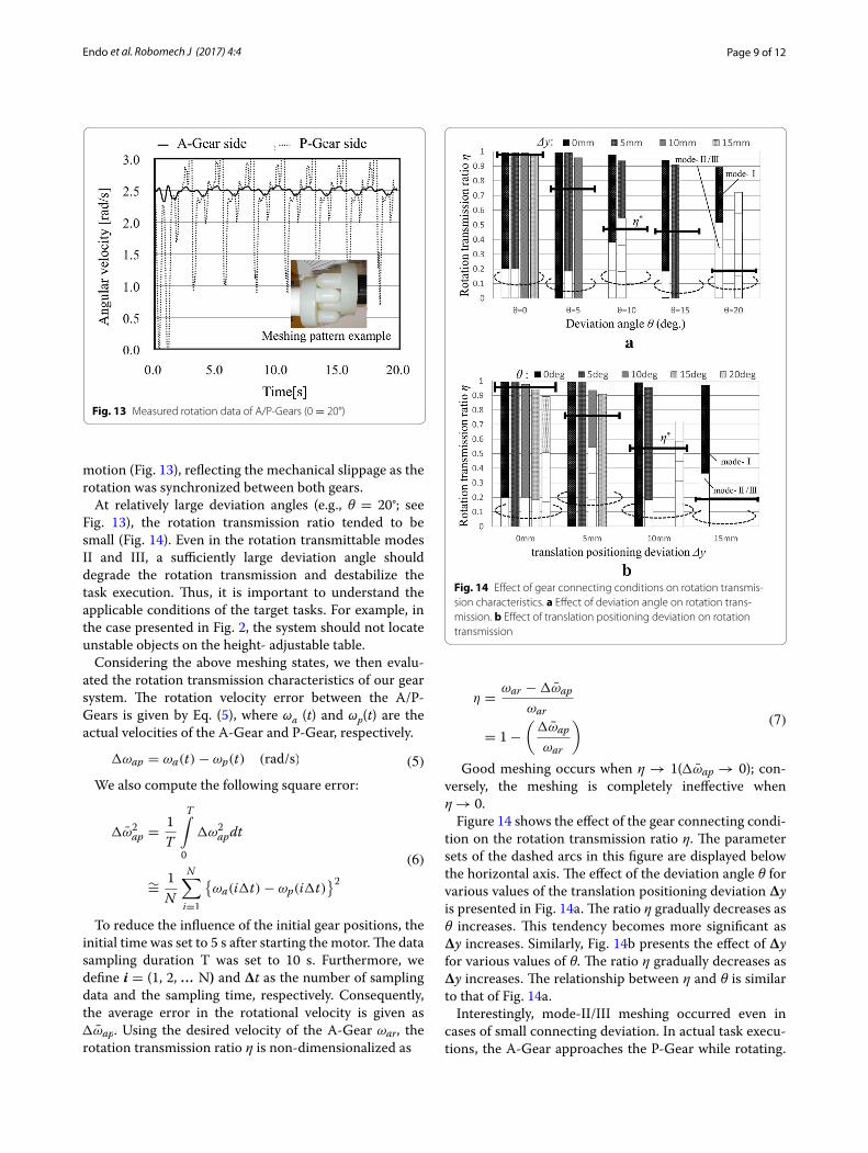
Figures 12 and 13 present some measured rotational data of the A/P-Gears. In these figures, the horizontal and vertical axes represent the rotation duration time and the angular velocity of the gears, respectively. For visual monitoring, the rotation speed was set to 2.5 rad/s. In the case of θ = 0° with Δy = 0 mm, the velocity of the P-Gear fluctuated slightly at relatively high frequency (see Fig. 12). However, after the meshing, the rotation speed of the P-Gear almost matched that of the A-Gear, indi-cating good meshing between the trident parts of both gears. Note that during one rotational period, the veloci-ties of the P- and A-Gears must deviate slightly in princi-ple, because the mechanical characteristics of this simple meshing pair are similar to those of a universal joint with non-constant velocity [19]. However, when θ = 20° with Δy = 0 mm, the velocity deviated significantly after 3 s of
Fig. 10 Block diagram of the A-Gear drive system control
Fig. 11 Experimental setup for measuring the gear rotation transmis-sion characteristics
Fig. 12 Measured rotation data of A/P-Gears (0 = 0°)
Page 9 of 12Endo et al. Robomech J (2017) 4:4
motion (Fig. 13), reflecting the mechanical slippage as the rotation was synchronized between both gears.
At relatively large deviation angles (e.g., θ = 20°; see Fig. 13), the rotation transmission ratio tended to be small (Fig. 14). Even in the rotation transmittable modes II and III, a sufficiently large deviation angle should degrade the rotation transmission and destabilize the task execution. Thus, it is important to understand the applicable conditions of the target tasks. For example, in the case presented in Fig. 2, the system should not locate unstable objects on the height- adjustable table.
Considering the above meshing states, we then evalu-ated the rotation transmission characteristics of our gear system. The rotation velocity error between the A/P-Gears is given by Eq. (5), where ωa (t) and ωp(t) are the actual velocities of the A-Gear and P-Gear, respectively.
We also compute the following square error:
To reduce the influence of the initial gear positions, the initial time was set to 5 s after starting the motor. The data sampling duration T was set to 10 s. Furthermore, we define i = (1, 2, … N) and Δt as the number of sampling data and the sampling time, respectively. Consequently, the average error in the rotational velocity is given as �ω̄ap. Using the desired velocity of the A-Gear ωar, the rotation transmission ratio η is non-dimensionalized as
(5)�ωap = ωa(t)− ωp(t) (rad/s)
(6)
�ω̄2ap =
1
T
T∫
0
�ω2apdt
∼=1
N
N∑
i=1
{
ωa(i�t)− ωp(i�t)}2
Good meshing occurs when η → 1(�ω̄ap → 0); con-versely, the meshing is completely ineffective when η → 0.
Figure 14 shows the effect of the gear connecting condi-tion on the rotation transmission ratio η. The parameter sets of the dashed arcs in this figure are displayed below the horizontal axis. The effect of the deviation angle θ for various values of the translation positioning deviation Δy is presented in Fig. 14a. The ratio η gradually decreases as θ increases. This tendency becomes more significant as Δy increases. Similarly, Fig. 14b presents the effect of Δy for various values of θ. The ratio η gradually decreases as Δy increases. The relationship between η and θ is similar to that of Fig. 14a.
Interestingly, mode-II/III meshing occurred even in cases of small connecting deviation. In actual task execu-tions, the A-Gear approaches the P-Gear while rotating.
(7)
η =ωar −�ω̄ap
ωar
= 1−
(
�ω̄ap
ωar
)
Fig. 13 Measured rotation data of A/P-Gears (0 = 20°)
Fig. 14 Effect of gear connecting conditions on rotation transmis-sion characteristics. a Effect of deviation angle on rotation trans-mission. b Effect of translation positioning deviation on rotation transmission

Page 10 of 12Endo et al. Robomech J (2017) 4:4
Consequently, the initial pin contact of the A-Gear may be significantly eccentric despite the low connect-ing deviation, resulting in mode-II/III meshing. As the connection condition worsens, the rotation transmis-sion ratio deteriorates, and the incidence of II/III modes increases.
Each side bar (thick horizontal line segment) in Fig. 14 indicates the arithmetic mean η* of the measured trans-mission ratios. η* can be considered as the average rota-tion transmission efficiency. In both panels (a and b), η* gradually decreases from approximately 1.0 as the con-necting error increases.
According to Fig. 14, the transmission efficiency η* is 0.5 or higher at Δy = 10 mm, but falls below 0.5 when θ ≥ 10°. These results imply that when optimizing the robot motion control strategy, we should minimize the deviation angle θ, even at the expense of Δy, under the given experimental conditions.
When η* reduces to 0.5, ωp approximates 0.5ωa. This implies that only around 50% of A-Gear’s rotation is transmitted to the P-Gear. However, the desired task may still be completed by doubling the scheduled time.
Application to robot task executionFigure 15 overviews the A-Gear mounted on the mobile robot. As previously explained, the mobile robot approaches the P-Gear attached to a mechanical tool in the task environment. Figure 16 is a photograph of the P-Gear attached to the passive curtaining tool (compris-ing a pulley with a timing belt). The curtaining task per-formed by the robot system is shown in Fig. 17.
The motion control strategy of the robot system is “Coarse to Fine.” In objective tasks, the robot moves to the vicinity of the P-Gear along the pre-defined nomi-nal path. The laser range sensor mounted on the robot then scans the vicinity of the stay holding the P-Gear. The A-Gear and P-Gear are separated by 300–500 mm. At 500 mm separation, the distance accuracy of the laser range sensor (±10 mm) is almost maintained while the
horizontal resolution is below 5 mm. The stay is covered by flat plastic plates of thickness 5 mm. By laser-scanning the front facing plate of the stay, the system precisely determines the straight line across the face (within an angular deviation of several degrees) by applying LSM algorithm to the measured range data. The deviation angle between the A-Gear and P-Gear is then obtained. We emphasize that the necessary system localization for gear meshing can be achieved by equipping a commercial indoor robot with an adequate sensor.
The robot orientation is controlled to be orthogonal to the stay face. To this end, the computed face-plate line is maintained orthogonal to the rotation axis of the P-Gear. Conversely, the nominal position of the P-Gear is estimated by detecting the corner position of the stay. Because the relationships between the nominal posi-tions/orientations of the P-Gear and the stay are already known, the A-Gear can safely approach the P-Gear while rotating. As the corner intersects two plates, it is inevi-tably affected by assembly error. However, for increas-ing the transmission ratio in meshing, decreasing the deviation angle may be more effective than decreasing the deviated translation position (see Fig. 14). Conse-quently, laser range sensing can accurately localize the gear meshing actuator during objective tasking.
After adequate gear meshing, the system completed the curtaining in 20 s. The robot system is detailed in [20]. When an adequate passive mechanical element is attached to the P-Gear, this system performs a variety of tasks. A belt-and-pulley mechanism converts the P-Gear rotation to linear motion. A parallel gripper can also be constructed using the mechanism shown in Fig. 18. For connection with the A-Gear, the P-Gear can be mounted with a passive mechanical locking using a simple cam. In this case, the system can apply both traction and pushing to the desired object on the floor.
As presented in Fig. 14, the rotation transmission rate can exceed 50% if the deviations in inclination angle and
Fig. 15 Photograph of A-Gear mounted on the mobile robot
Passive toolP-Gear
Pulley and timing belt
Fig. 16 P-Gear attached to the passive curtaining tool

Page 11 of 12Endo et al. Robomech J (2017) 4:4
translational remain within 5° and 10 mm, respectively. Therefore, the developed meshing actuator can be imple-mented on a commercially available indoor mobile robot with appropriate sensors. However, the object-mounting P-Gear should have a simple and laser-detectable con-figuration, as shown in Fig. 16. The time of robot localiza-tion and the number of retries in task execution are often affected by the floor conditions, especially in residential situations.
ConclusionsWe have designed a rotational meshing actuator for a life support system based on a mobile robot. The present paper explains the basic concept of the actua-tor and its design details. The rotation transmission
characteristics of the actuator were experimentally investigated in an actuator prototype. Finally, the developed actuator was mounted on a mobile robot, and its practical feasibility was confirmed in a window curtaining experiment. The study results are summa-rized below.
1. The basic concept of the actuator was presented and its design procedures were explained. The paired actuator comprises a motor-controlled active mechanism (A-Gear) that mates with a pas-sive mechanism (P-Gear). The top of the A-Gear is fitted with a trident pin, which can mate with a similar pin on top of the P-Gear. Once engaged, rotational motion is transferred between the gears.
Fig. 17 Robot performing the window curtaining task

Page 12 of 12Endo et al. Robomech J (2017) 4:4
2. We investigated a relative-motion model of the gear meshing. The model accounts for the kinematic as well as the geometrical relationships at the con-necting joint of two adjacent links in 3-dimensional space. In a force analysis of the developed model, we revealed the generation of the rotation torque and its transmission between two meshed gears.
3. Using a prototype of the actuator, we experimentally evaluated the rotation transmission characteristics of the actuator. We identified three meshing patterns; namely, modesI, II, and III. In mode-I, the A-Gear and P-Gear mesh almost in the nominal position, with little positioning error. In modes II and III, the A/P-Gears only partially engage, and their common positioning error is relatively large. Although the rotation transmission efficiency deteriorated with increasing translational and angular deviation of the actuator positioning, the desired task could be com-pleted by doubling the scheduled time.
4. The developed actuator was mounted on a mobile robot, and the effectiveness of the actuator was demonstrated in a curtaining experiment. The developed actuator is relatively simple and can be constructed by a personal 3D printer, potentially realizing an effective personal life support system.
AbbreviationsADL: activities of daily living; REACH: robotic enhanced assistant co-existing in home; A-Gear: active Gear; P-Gear: passive Gear.
Authors’ contributionsME(1) proposed the basic concept of REACH system, designed and imple-mented the Gear system, conducted the experiment, analyzed experimental results, and drafted the manuscript. ME(2) designed the control system of the mobile robot system, designed and implemented the information processing system. TK proposed the Gear dynamics model, confirmed the experimental results. All authors read and approved the final manuscript.
AcknowledgementsThe authors would like to thank Mr. Hiromasa Fukushi, a former graduate student of Sustainable Systems Design Laboratory, Mechanical Engineering
Department, the College of Engineering, Nihon University for his dedicated support of the intensive experiment.
Competing interestsThe authors declare that they have no competing interests.
Received: 30 December 2015 Accepted: 27 December 2016
References 1. Japan Cabinet Office (2014) Annual Report on the Aging Society (in
Japanese) 2. Bolmsjo G, Neveryd H, Eftring H (1995) Robotics in rehabilitation. IEEE
Trans Rehabil Eng 3(1): 77–83 3. Schraft RD, Schaeffer C, May T, (1998) Care-O-bot™: the concept of a
system for assisting elderly or disabled persons in home environments. In: Proceedings of the 24th annual conference of the IEEE industrial electronics society, vol 4, pp 2476–2481
4. Machiel F, Reinkensmeyer D (2008) Rehabilitation and health care robot-ics. Springer Handbook of Robotics, New York, pp 1223–1251
5. Broadbent ER, Stafford R, MacDonald B (2009) Acceptance of healthcare robots for the older population: review and future directions. Int J Soc Robot 1(4): 319–330
6. Broadbent E, Jayawardena C, Kerse N, Stafford R, MacDonald BA (2011) Human–robot interaction research to improve quality of life in elder care—an approach and issues. In: Workshop on human–robot interac-tion in elder care, 25th conference on artificial intelligence, pp 13–19
7. Smarr C, Fausset B, Wendy R (2011) Understanding the potential for robot assistance for older adults in the home environment, human factors and aging laboratory technical reports. Georgia Institute of Technology, School of Psychology, Atlanta
8. Mizukawa M (2005) Robot technology (RT) trend and standardization. IEEE Workshop Adv Robot Soc Impacts 12(15): 249–253
9. Balaguer C, Gimenez A, Jardon A, Cabas R, Correal R (2005) Live experi-mentation of the service robot applications for elderly people care in home environments. IEEE/RSJ Int Conf Intell Robots Syst 2(6): 2345–2350
10. Chung W, Kim G, Kim M (2007) Development of the multi-functional indoor service robot PSR systems. Auton Robots 22(1): 1–17
11. Jain A, Kemp C (2010) EL-E: an assistive mobile manipulator that autono-mously fetches objects from flat surfaces. Auton Robots 28(1):45–64
12. Mori T, Sato T (1999) Robotic room: its concept and realization. Robot Auton Syst 28(2–3): 141–148
13. Sato T, Harada T, Mori T (2004) Environment-type robot system “Robotic Room” featured by behavior media. IEEE/ASME Trans Mechatron Behav Contents Behav Adapt 9(3): 529–534
14. Mori T, Hayama N, Noguchi H, Sato T (2004) Informational support in distributed sensor environment sensing room. In: 13th IEEE interna-tional workshop on robot and human interactive communication (RO MAN2004), pp 353–358
15. Endo M, Sekiguchi K, Endo M, Kakizaki T (2012) A life support system utilizing support provided by a physical agent: a prototype of a control interface based on hand gesture. In: Proceeding of JSME robotics and mechatronics conference, vol 12, no 3 (in Japanese)
16. Ueda S, Hasegawa T, Ando K, Sakuma A, Kusunoki T (1985) Standardi-zation of the finger function test and upper extremity ability test for hemiplegia. Jpn J Rehabil Med 22(3): 143–160 (in Japanese)
17. Toyota Motor Company (2015) Toyota shifts home helper robot R&D into high Gear with new developer community and upgraded prototype, TOYOTA Global news room, July 16
18. Kakizaki T, Deck JF, Dubowsky S (1993) Modeling the spatial dynamics of robotic manipulators with flexible links and joint clearances. ASME J Mech Des 115(4): 839–847
19. Mabie H, Reinholtz C (1987) Mechanisms and dynamics of machinery, 4th edn. Wiley, New York
20. Endo M, Endo M, Kakizaki T (2012) A life support system utilizing supports provided by a physical agent. JSME Robot Mechatron Conf 12(3): 1–4 (in Japanese)
P-GearParallel gripper Pulley and timing belt unit
Fig. 18 P-Gear attached to the passive gripper tool