development of a re-configurable mechatronic … · mechatronic platform for college students’...
TRANSCRIPT

MQP
Development of a Re-configurable Mechatronic Platform for college
students’ multi-discipline experiments A Major Qualifying Project Report Worcester Polytechnic Institute
September 7th , 2011
Submitted to:
Advisor: Prof. Yiming (Kevin) Rong, WPI ME Professor
Advisor: Prof. Lingsong He, HUST Professor
Sponsor: DEPUSH Technology Ltd.
Submitted by:
Fengjing Chai (HUST)
Patrick Scott (WPI)
Li Wang (HUST)
Yiming Wu (WPI)
Xinyan Zhao (HUST)

1
Acknowledgement The team would like to thank our sponsor DEPUSH Technology Company for their valuable
support and suggestions during the whole process of the project. We would not have been successful without the help from the faculty, staff, and the resources provided by Huazhong University of Science and Technology. We would also like to thank our advisors, Professor Kevin Rong from WPI, and Professor Lingsong He from HUST, for their precious guidance prior to, during, and after the project.

2
Abstract To meet the increasing need of the multi-disciplinary engineering education and to provide a re-
configurable mechatronic experiment platform, the team seeks to plan, design, and validate a mechatronic platform that allows simple model re-assembling and re-configurability. This platform also employs the concept of modular and expandable design. It consists of reconfigurable mechanical structures, diverse sensor applications, microcontroller and motor controller control system, and graphical user interfaces on PC terminal for multi-disciplinary learning experience.

3
Table of Contents Acknowledgement ........................................................................................................................................ 1
Abstract ......................................................................................................................................................... 2
Table of Figures ............................................................................................................................................. 7
List of Tables ................................................................................................................................................. 9
1. Introduction ............................................................................................................................................ 10
1.1 Problem statement ........................................................................................................................... 10
1.2 Project scope ..................................................................................................................................... 10
1.3 Project value ..................................................................................................................................... 11
1.4 Expected results ................................................................................................................................ 12
2. Background ............................................................................................................................................. 13
2.1 What does the educational platform help students with? ............................................................... 13
2.2 Mechanical structures research ........................................................................................................ 13
2.2.1 Product of DEPUSH Technology ................................................................................................. 13
2.2.2 Product of BOSIWEILONG .......................................................................................................... 15
2.2.3 Product of LEGO ......................................................................................................................... 16
2.2.4 Product of Fischertechnik .......................................................................................................... 18
2.2.5 Mechanical education platform in HUST ................................................................................... 20
2.2.6 Summary of mechanical part research ...................................................................................... 21
2.3 Case study on a mechatronic platform ............................................................................................. 23
2.4 Our idea of reconfigurable logistics platform ................................................................................... 27
2.5 Electrical part research ..................................................................................................................... 28
2.5.1 LEGO Mindstorms ...................................................................................................................... 28
2.5.2 ROBO TX Training Lab ................................................................................................................ 29
2.5.3 VEX Robotic Design System ........................................................................................................ 29
2.6 Technologies used in mechatronic platform .................................................................................... 29
2.6.1 Microcontrollers......................................................................................................................... 29
2.6.2 Motor control system ................................................................................................................ 31
2.6.3 Sensors ....................................................................................................................................... 33
2.6.4 Communication .......................................................................................................................... 34
2.7 Upper PC interface development environment research ................................................................. 35
4
2.7.1 LabVIEW vs. C language for Control system user interface design ............................................ 35
2.7.2 LabView features consideration ................................................................................................ 35
3. Methodology ........................................................................................................................................... 37
3.1 Flow chart for overall system design ................................................................................................ 37
3.2 Functional diagram of the overall system ......................................................................................... 38
3.3 Techniques used to achieve the objectives ...................................................................................... 40
3.3.1 Design overview ......................................................................................................................... 40
3.3.2 Design a flexible and stable installation scheme ....................................................................... 40
3.3.3 Modular and building-block design ........................................................................................... 41
3.3.4 Multi-disciplinary design ............................................................................................................ 42
3.4 General plan ...................................................................................................................................... 42
4. Results ..................................................................................................................................................... 43
4.1 Results of the mechanical part ......................................................................................................... 43
4.1.1 Design the connecting method .................................................................................................. 43
4.1.2 Design various general purpose modules .................................................................................. 45
4.1.2.1 Design linear motion module .................................................................................................. 48
4.1.2.2 Design pneumatic actuating module ...................................................................................... 49
4.1.2.3 Design conveyor belt module ................................................................................................. 50
4.1.2.4 Design valves and pipe junctions ............................................................................................ 52
4.1.3 Build models and design special purpose modules ................................................................... 53
4.1.3.1 Model A – Automated Warehouse ......................................................................................... 54
4.1.3.2 Design pneumatic schematics for Model A ............................................................................ 56
4.1.3.3 Design special purpose modules –goods module design ....................................................... 58
4.1.3.4 Design special purpose modules –goods table and brace ...................................................... 59
4.1.3.5 Design special purpose modules –vacuum cup ...................................................................... 59
4.1.3.6 Build model B – X-Y plotter ..................................................................................................... 60
4.1.3.7 Build model C – cubic warehouse ........................................................................................... 62
4.1.4 Determine specification for accessories .................................................................................... 63
4.1.5 Complete 2D drawings and manufacturing ............................................................................... 65
4.1.6 Real Model A assembling and Model B re-assembling .............................................................. 65
4.1.7 Summary for mechanical part .................................................................................................... 68

5
4.2 Results of the electrical part ............................................................................................................. 69
4.2.1 AT89C52 VS STM32F107VC ........................................................................................................ 69
4.2.2 Overall system architecture ....................................................................................................... 70
4.2.3 Overall system pins layout ......................................................................................................... 72
4.2.4 Relay driver circuit ..................................................................................................................... 74
4.2.5 DC motor controller ................................................................................................................... 75
4.2.6 Stepper motor controller ........................................................................................................... 76
4.2.7 Sensor applications .................................................................................................................... 78
4.2.7.1 Goods’ Validation Subsystem Infrared proximity sensor ....................................................... 78
4.2.7.2 Information Acquisition Subsystem - Barcode scanner .......................................................... 82
4.2.8 Summary of electrical system .................................................................................................... 84
4.3 Result of PC graphical user interface (GUI) ....................................................................................... 85
4.3.1 Automatic warehouse GUI ......................................................................................................... 85
4.3.2 X-Y plotter GUI .......................................................................................................................... 86
4.3.3 GUI design summary .................................................................................................................. 87
5. Conclusion ............................................................................................................................................... 88
5.1 Achievements ................................................................................................................................ 88
5.2 Recommendations ........................................................................................................................ 88
5.2.1 Develop easier assembly methods ............................................................................................ 88
5.2.2 Develop more general purpose modules................................................................................... 89
5.2.3 Improvement of existing modules ............................................................................................. 89
5.2.4 Enhance mechatronic principles and modularity ...................................................................... 90
5.3 Limitation of our work .................................................................................................................. 91
5.3.1 Complicated wiring and pipe arrangement ............................................................................... 91
5.3.2 Limited modules ......................................................................................................................... 91
5.3.3 Limited modularity of user interfaces ........................................................................................ 91
Appendix A – Source Code .......................................................................................................................... 92
Appendix A.1 - main.c ............................................................................................................................. 92
Appendix A.2 - cylinder_motor.c .......................................................................................................... 104
Appendix A.3 - stm32f10x_it.c .............................................................................................................. 110
Appendix A.4 – main.c .......................................................................................................................... 118

6
Appendix A.5 – stm32f10x_it.c ............................................................................................................. 142
Appendix B – LabVIEW Code ..................................................................................................................... 150
Appendix B.1 – Automated warehouse GUI LabVIEW code ................................................................. 150
Appendix B.2 – X-Y plotter GUI LabVIEW code ..................................................................................... 151
References ................................................................................................................................................ 152

7
Table of Figures FIGURE 1 - TWO-DIMENSIONAL OR THREE-DIMENSIONAL RECONFIGURABLE X-Y CNC TABLE ........................................................... 14
FIGURE 2 - DISPLACEMENT AND DISTANCE TESTING TABLE ........................................................................................................ 15
FIGURE 3 - EDUCATIONAL PLATFORM PRODUCT ..................................................................................................................... 15
FIGURE 4 - PLASTIC SOLUTION FOR MECHANICAL COMPONENTS ................................................................................................. 16
FIGURE 5 – LEGO OFFICIAL SITE SCREENSHOT ........................................................................................................................ 17
FIGURE 6 - LEGO PING-PONG BALL COLLECTING ROBOT AND FOUR WHEELS ROBOT ..................................................................... 17
FIGURE 7 – CHAIN ARCHITECTURE ....................................................................................................................................... 18
FIGURE 8 - INDUSTRIAL MODELS ......................................................................................................................................... 19
FIGURE 9 – PLASTIC COMPONENTS FROM FISCHERTECHNIK ...................................................................................................... 19
FIGURE 10 – CUBOIDS THAT CAN BE SPLICED FROM SIX SIDES .................................................................................................... 20
FIGURE 11 – CUBOIDS CONNECTION .................................................................................................................................... 20
FIGURE 12 - CONNECTORS ................................................................................................................................................. 21
FIGURE 13 – OTHER ACCESSORIES ....................................................................................................................................... 21
FIGURE 14 – CONNECTION METHODS ................................................................................................................................... 22
FIGURE 15 – SOME BASIC ASSEMBLY MECHANISMS ................................................................................................................. 22
FIGURE 16 - OVERALL VIEW OF MECHATRONIC PLATFORM ........................................................................................................ 24
FIGURE 17 – CONVEYOR STATION ........................................................................................................................................ 24
FIGURE 18 – MATERIALS PROCESSING WITH Z-AXIS HANDLING DEVICE ........................................................................................ 25
FIGURE 19 – AUTOMATED STORAGE AND RETRIEVAL SYSTEM .................................................................................................... 26
FIGURE 20 – TWO TYPES OF CUBIC WAREHOUSE MODELS ......................................................................................................... 27
FIGURE 21 – EXAMPLES OF MODULE FAMILY .......................................................................................................................... 28
FIGURE 22 – DC MOTOR CONTROLLER.................................................................................................................................. 33
FIGURE 23 - LABVIEW FRONT PANEL AND BLOCK DIAGRAM ...................................................................................................... 36
FIGURE 24 – FLOW CHART OF DESIGN PROCESS ...................................................................................................................... 37
FIGURE 25 – FLOW CHART FOR DETAIL FUNCTION DESIGN ......................................................................................................... 38
FIGURE 26 – FUNCTIONAL BLOCK DIAGRAM OF THE OVERALL SYSTEM ......................................................................................... 39
FIGURE 27 BLACK BOX DIAGRAM OF AUTOMATIC WAREHOUSE .................................................................................................. 40
FIGURE 28 – GANTT CHART ................................................................................................................................................ 42
FIGURE 29 – LEGO’S BUILDING BLOCKS ................................................................................................................................ 44
FIGURE 30 – FRAMEWORK AND CONNECTING METHOD ............................................................................................................ 45
FIGURE 31 – QUANTITY OF DIFFERENT MODULES USED IN THE PLATFORM .................................................................................... 46
FIGURE 32 – EXAMPLES OF GENERAL PURPOSE MODULES ......................................................................................................... 47
FIGURE 33 – TWO OPTIONS FOR LINEAR MOTION MODULE ....................................................................................................... 48
FIGURE 34 – PNEUMATIC ACTUATING MODULES ..................................................................................................................... 50
FIGURE 35 – TWO OPTIONS FOR CONVEYOR BELT MODULE ....................................................................................................... 51
FIGURE 36 – VALVES AND PIPE JUNCTION MODULES ................................................................................................................ 52
FIGURE 37 – THREE DIFFERENT MODELS IN OUR PLATFORM ...................................................................................................... 53
FIGURE 38 – VENN DIAGRAM OF NUMBER OF MODULES .......................................................................................................... 54
FIGURE 39 – ORIGINAL IDEAS FOR MODEL A ........................................................................................................................ 55
FIGURE 40 – SPECIAL PURPOSE MODULES ............................................................................................................................. 56
FIGURE 41 – PNEUMATIC SCHEMATICS FOR THE WAREHOUSE .................................................................................................... 57
FIGURE 42 – TWO OPTIONS FOR GOODS DESIGN ..................................................................................................................... 58
FIGURE 43 – TWO OPTIONAL MATERIALS FOR GOODS DESIGN ................................................................................................... 59
FIGURE 44 – EXPLORED VIEW OF THE TRANSPORTATION TABLE .................................................................................................. 59

8
FIGURE 45 – WORKING PRINCIPLE FOR VACUUM GENERATOR ................................................................................................... 60
FIGURE 46 – DESIGN OPTIONS FOR PEN HOLDER ..................................................................................................................... 62
FIGURE 47 – VACUUM CUP SCHEMATIC ................................................................................................................................ 64
FIGURE 48 – FINAL ASSEMBLY OF MODEL A .......................................................................................................................... 66
FIGURE 49 – FINAL ASSEMBLY OF X-Y PLOTTER ...................................................................................................................... 67
FIGURE 50 – OVERALL SYSTEM ARCHITECTURE ....................................................................................................................... 70
FIGURE 51 – FLOW CHART FOR MODEL A ............................................................................................................................. 71
FIGURE 52 – FLOW CHART FOR MODEL B ............................................................................................................................. 72
FIGURE 53 – FLOW CHART OF THE OVERALL SYSTEM ................................................................................................................ 72
FIGURE 54 – SCHEMATIC OF RELAY DRIVER ............................................................................................................................ 75
FIGURE 55 – SCHEMATIC FOR DC MOTOR CONTROLLER ........................................................................................................... 76
FIGURE 56 – SIGNAL INPUTS OF THE STEPPER MOTOR CONTROLLER ............................................................................................ 77
FIGURE 57- FUNCTIONAL BLOCK DIAGRAM OF THE GOODS’ VALIDATION SUBSYSTEM ...................................................................... 78
FIGURE 58 – FUNCTIONAL BLOCK OF THE INFRARED PROXIMITY SENOR ........................................................................................ 79
FIGURE 59 – SENSOR MEASUREMENT SETUP .......................................................................................................................... 80
FIGURE 60 – MEASUREMENT RESULT ................................................................................................................................... 80
FIGURE 61 – PHYSICAL INSTALLATION OF THE INFRARED PROXIMITY SENSOR ................................................................................. 81
FIGURE 62 - FUNCTIONAL BLOCK DIAGRAM FOR INFORMATION ACQUISITION SUBSYSTEM ............................................................... 83
FIGURE 63 – AUTOMATED WAREHOUSE GUI ......................................................................................................................... 86
FIGURE 64 – GUI OF THE X-Y PLOTTER ................................................................................................................................. 87
FIGURE 65 – SNAP FIT ....................................................................................................................................................... 89
FIGURE 66 – LABVIEW CODE FOR THE AUTOMATED WAREHOUSE GUI .................................................................................... 150
FIGURE 67 – LABVIEW CODE OF THE X-Y PLOTTER ................................................................................................................ 151

9
List of Tables Table 1 – Air compressor specification ....................................................................................................... 63
Table 2 – Modules used in Model A ............................................................................................................ 66
Table 3 – Modules used in Model B ............................................................................................................ 68
Table 4 – Requirements/Specifications ...................................................................................................... 69
Table 5 – Pins layout of the overall system ................................................................................................ 73
Table 6 – Configuration of UARTs ............................................................................................................... 83

10
1. Introduction In the introduction chapter, the discussion of the problem statement provides the team a better
understanding of the project and helps us to define the scope of the project. With the definition of the
scope, the value of the project and the expected results will also be discussed.
1.1 Problem statement
There is an increasing need for multi-disciplinary education, especially in the engineering
education. Nowadays, the mechanical engineering students not only study the knowledge in mechanical
field, but also use computers to do simulations or modeling work. Besides the use of computers,
electrical components such as relays, motor driver, and microcontroller control system are also
frequently studied. The Robotics major is another example of using multiple disciplines to teach
students in the engineering field. There are also many existed products on the market such as LEGO, VEX
tend to provide solutions not only for multi-disciplinary learning experience, but also for a re-
configurable platform, though they are not completely successful. LEGO’s products employ a modular,
building-block design which allows re-using or re-assembling some of the components to build different
models, but these models usually fragile and cannot be used for high power applications. Educational
mechatronic platform that can be adjusted according to different needs of the students doesn’t exist.
Our sponsor Depush Technology would like to develop such a reconfigurable experiment platform for
mechatronic engineering students. The need of a multi-disciplinary reconfigurable experiment
mechatronic platform is the main driving force of this project.
1.2 Project scope In order to achieve the goal of developing a multi-disciplinary reconfigurable experiment
mechatronic platform, the team attempts this project by using the following methods to simplify the
development process:
- Method 1 – Find concepts or principles involved in mechatronic engineering

11
- Method 2 – Employ modular design and define module property based on needs
- Method 3 – Choose a few mechatronic models to study and find out similarities and
differences between mechatronic models
The team also defines the objectives based on the time and technical constraints as follows:
- Objective 1 – Include at least two aspects of knowledge in mechanical engineering and
electrical engineering
- Objective 2 – Separate the modules into general purpose module and special purpose
module
- Objective 3 – Complete at least two mechatronic models by using some or all of the
modules designed
To validate our design concept, the two mechatronic models chosen are an Automated
Warehouse Model and an X-Y plotter. These two models will be built with most general purpose
modules and several special purpose modules.
1.3 Project value Educational mechatronic platforms which fulfill individual functions already exist. For
examples, there are XY plotter, automated warehouse model, inverted pendulum, and
educational robots. From those models above, students can learn about sensor signal
obtaining, motor driver, mechanical transmission, microcontroller programming, PC
programming and other knowledge. However, those platforms have definite functions, which
mean that they can’t be adjusted according to the needs of the students. Mechanical
engineering also requires high stability and reliability in the platform. Different components are
rigidly connected together and can’t be adjusted according to the need of the students. If those
12
components can be made into different modules and allow simple model re-assembling,
students can have more choices in designing and building their own models. This helps to build
up students’ ability in dealing with multi-disciplinary projects. That is what we want to achieve
in our reconfigurable platform.
1.4 Expected results By the end of the project, a multi-disciplinary and highly reconfigurable educational mechatronic
platform will be built. This platform has a module library that covers the most commonly used functions
and is highly interchangeable. Those modules can be easily and firmly assembled together to build
various engineering models. At the same time, they can be intact disassembled and reused in building
other models. The platform can provide the students a multi-disciplinary learning experience including
diverse sensor applications, embedded microcontroller control and upper PC programming. At the same
time, we will use the designed modules to build as many models as possible in the 3D software model to
justify its re-configurability. We will manufacture the modules and build a real multi-disciplinary
engineering model. Then, we will perform microcontroller and PC control on the model to fulfill specific
tasks. If time permits, we will disassemble the first model to build another model to justify the re-
configurability of our platform in practice.

13
2. Background In the background chapter, general background information about the mechanical
structure, electrical components, upper PC will be discussed. We mainly do a comprehensive
survey on all the existing products we can find and discover possible options for our platform.
2.1 What does the educational platform help students with?
As mentioned above, the goal of the project is to design and implement a reconfigurable
educational platform for mechatronic students. Mechatronics is the combination
of Mechanical engineering, Electronic engineering, Computer engineering, Software
engineering, Control engineering, and Systems Design engineering in order to design, and
manufacture useful products. Mechatronics is a multidisciplinary field of engineering, that is to
say it rejects splitting engineering into separate disciplines. In this case, this educational
platform should provide opportunities to learn the following knowledge:
1. Mechanical structure and transmission
2. Upper PC interface design
3. Microcontroller programming and control system design
4. Sensor applications
2.2 Mechanical structures research In order to better understand the current situation of educational platforms for college
students, we did a comprehensive research on the existing products. Those mechanical
structures can provide us basic idea about the current educational platforms. The following is
some information and analysis about those products.
2.2.1 Product of DEPUSH Technology DEPUSH Technology is specialized in engineering education innovation. It mainly develops
laboratory platforms for universities. It offers vocational classes for Innovation Lab program from the

14
engineering design, consulting, laboratory equipment and system development, to the laboratory
building construction and teacher training in the full range of services. Currently, DEPUSH’s engineering
facility products are innovative laboratory systems, which include DRLab and DRRob. DRLab series is
"DRVI Reconfigurable Virtual Instrument". "DRLink’’ fast reconfigurable computer controlled platform" is
the core. It is developed for electrical and electronic, test, and control technology courses. This
innovative experimental platform includes software, hardware, and a full set of engineering objects
system. DRRob series is a robot platform, covering machinery, electronics, sensing and control, and other
disciplines. It provides training in basic engineering, basic professional education and professional
education.
Figure 1 - Two-dimensional or three-dimensional reconfigurable X-Y CNC table1
1 Figure Cited: http://www.depush.com/

15
Figure 2 - Displacement and distance testing table
2.2.2 Product of BOSIWEILONG Different building blocks are used in this company’s platform to build this system.
Several different sensors are added to detect the motion of some parts. Programmed
controllers can control the system to fulfill desired tasks.
Figure 3 - Educational Platform Product2
In order to provide a mini-scale engineering educational platform, this company
provides a list of components and pictures of plastic gears. The components include both
mechanical blocks and electronic blocks. All of these blocks are mainly made of plastic. They
can be made into different precisions to meet the need of different customers. However, those
plastic modules will be easily deformed under external force. This platform only performs well
2 Figure Cited: http://www.bds-tech.com/newproduct_11.php

16
with light load. It cannot provide learning experience close to real life engineering product.
Figure 4 - Plastic solution for mechanical components
2.2.3 Product of LEGO The company's flagship product, Lego, consists of colorful interlocking plastic bricks and
an accompanying array of gears, mini-figures and various other parts. Lego bricks can be
assembled and connected in many ways, to construct such objects as vehicles, buildings, and
even working robots. Anything constructed can then be taken apart again, and the pieces used
to make other objects.

17
Figure 5 – LEGO official site screenshot3
Lego initiated a robotics line of toys called “Mindstorms” in 1998, and has continued to
expand and update this range ever since. The roots of the product originate from a
programmable brick developed at the MIT Media Lab, and the name is taken from a paper by
Seymour Papert, a computer scientist and educator who developed the educational theory of
constructionism, and whose research was at times funded by the Lego Group.
The programmable Lego brick which is at the heart of these robotics sets has undergone
several updates and redesigned, with the latest being called the 'NXT' brick, being sold under
the brand name of Lego Mindstorms NXT 2.0. The set includes sensors that detect touch, light,
sound and ultrasonic waves, with several others being sold separately, including an RFID reader.
Figure 6 - LEGO Ping-Pong Ball Collecting Robot and four wheels robot
3 Figure Cited: http://www.lego.com/en-us/Default.aspx
18
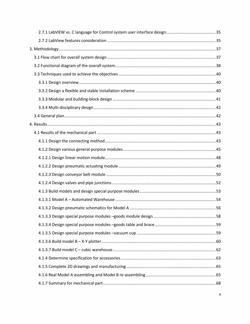
They also build a reconfigurable Multi Robot Society based on LEGO Mindstorms. A
modular robotics group in a space application using Chain architecture, modules can be seen
performing different tasks, such as welding, replacing faulty units, assembly and more.
Figure 7 – Chain Architecture
Lego’s platform resembles the product of previous research. However the same
problem exists. Those modules are made of plastic that will be easily deformed under external
force. This platform only performs well with light load. At the same time, Lego’s product has the
feature of building blocks which means that every time the model should be built from scratch.
In engineering education, this method is too complicated and unnecessary. It cannot provide
learning experience close to real life engineering product either.
2.2.4 Product of Fischertechnik
In the platform provided by the Fischertechnik, the basic building blocks were of
channel-and-groove design, manufactured of hard nylon. Basic blocks came in 15x15x15 and
15x15x30 millimeter sizes. A peg on one side of each block could be attached into a channel on
any of the other five sides of a similar block, producing a tightly-fitting assembly that could

19
assume almost any shape. Typical connectors of Fischer are useful for reference though there
are difference between plastic and aluminum.
Figure 8 - Industrial Models
4
The Fischertechnik Company develops a set of mechanical components family. Those
components are made of plastic so that it is simple and flexible. This idea of building a
reconfigurable platform is similar to the idea of Lego, so that the same problem exists.
The defects include the stiffness of the platform and unnecessary effort in building all
the things from scratch again. However, its connection method is worth of study and
maybe useful for our future design.
Figure 9 – Plastic Components from Fischertechnik
4 Figure Cited: http://www.fischertechnik.de/en/home.aspx
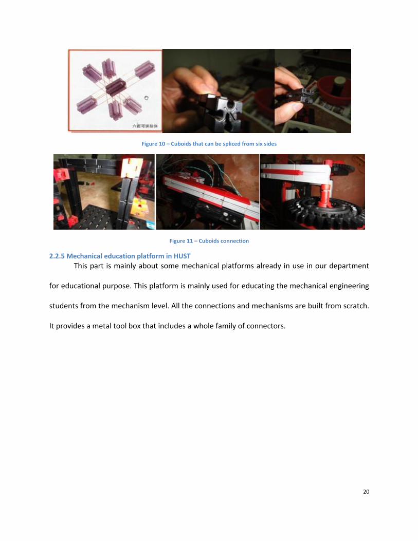
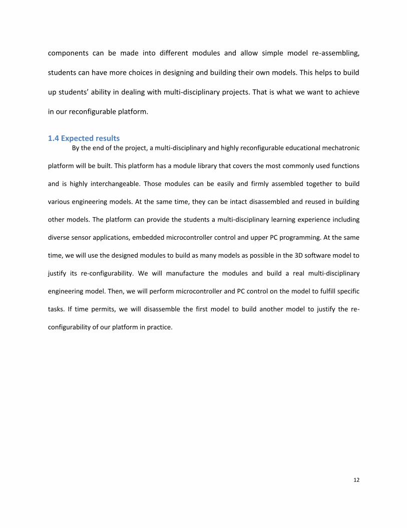
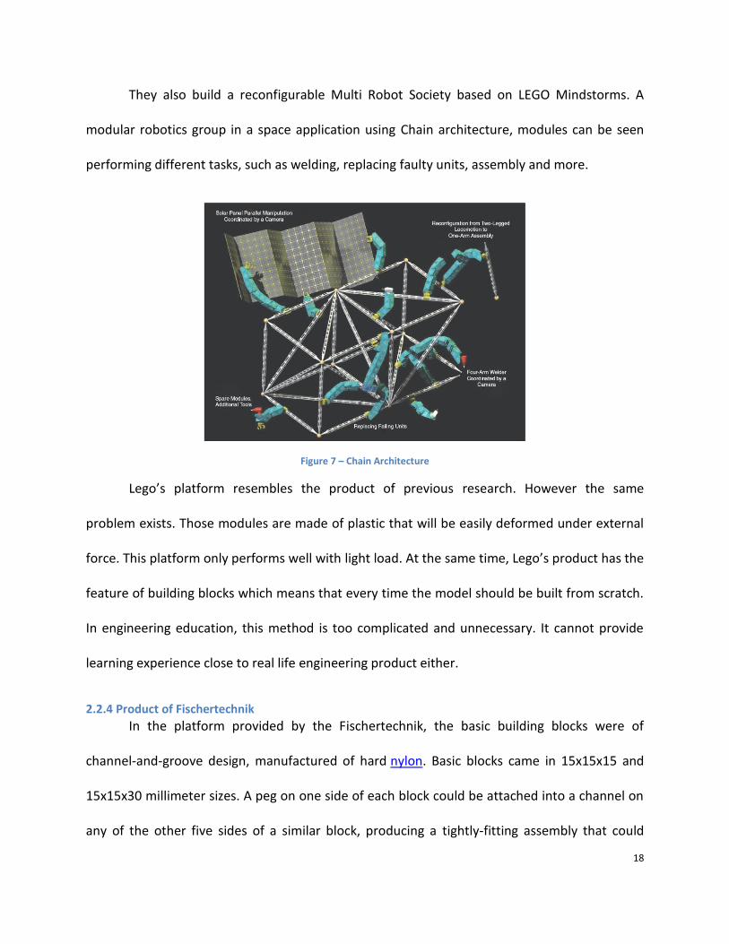
20
Figure 10 – Cuboids that can be spliced from six sides
Figure 11 – Cuboids connection
2.2.5 Mechanical education platform in HUST This part is mainly about some mechanical platforms already in use in our department
for educational purpose. This platform is mainly used for educating the mechanical engineering
students from the mechanism level. All the connections and mechanisms are built from scratch.
It provides a metal tool box that includes a whole family of connectors.

21
Figure 12 - Connectors
To cover all the knowledge in mechanical theory, this platform includes other
accessories,like rod connector, gears, cam and other mechanism. All these components
together ensure a comprehensive understanding of mechanisms.
Figure 13 – Other accessories
2.2.6 Summary of mechanical part research
After careful and comprehensive study on the platform, we find some valuable
connection method that can be our design option. On example is some frequently used
connecting method that is highly worthy of reference. Those methods include vertical and
horizontal interconnection: Vertical interconnection method uses angled aluminum, with T-slot

22
nut type; horizontal interconnection method uses convex and concave connection. These two
methods are shown in figure 14 below.
Figure 14 – Connection methods
In order to demonstrate the basic functions of the mechanical mechanisms, we can use
those components to build some frequently used models and mechanisms.
Figure 15 – Some basic assembly mechanisms

23
This platform is a perfect platform for the education of basic mechanism theory. It
includes almost all the basic knowledge required by this course. And it can provide the student
a perfect chance of creating their own model. The problem is that this is only a mechanical
model. It cannot provide the multi-disciplinary experience required by the customer. A lot of
work needs to be done to incorporate electrical and computer science knowledge into this
platform.
2.3 Case study on a mechatronic platform
In the whole process of research, one product gets our special attention. This is a
platform made by Matrix Multimedia Limited. We do a comprehensive research on this
platform since our idea is very close to this series of products. There are mainly 3 differences
between our platform and their product.
1. Most of the components they use are manufactured by themselves. Our platform
will use some standard parts that can be bought from the market to cut down the
price. Our design will mainly focus on the design of connectors to make this platform
reconfigurable.
2. They mainly use pneumatic transmission as the transmission method. Our platform
will use stepper motor and screw rod instead.
3. They use PLC to build up the control system. Our platform uses micro controllers and
use wireless control. There will be more sensors.

24
Figure 16 - Overall view of mechatronic platform5
This platform can be divided into three smaller models according to their respective
functions. We analyze the composition of the three models and try to find out the valuable
aspects we can learn from the models.
Figure 17 – Conveyor station
Inspirations from this model are as follows:
5 Figure Cited: http://www.matrixmultimedia.com/

25
1. Make the goods all kinds of different colors ,not only black and white
2. Design new warehouse
3. Use sensors: detect by weight, by color or others
4. Use stepper motor and screw rod instead of pneumatic pressure as transmission
component
5. Use T-slot base as base for our platform.
6. Use nuts and bolts to connect different components on the base
Figure 18 – Materials processing with z-axis handling device
Inspirations from this model are as follows:
1. Use stepper motor and screw rod instead of pneumatic pressure as transmission
component.
2. Use T-slot base as base for our platform. (Use nuts and bolts to connect different
26
components on the base)
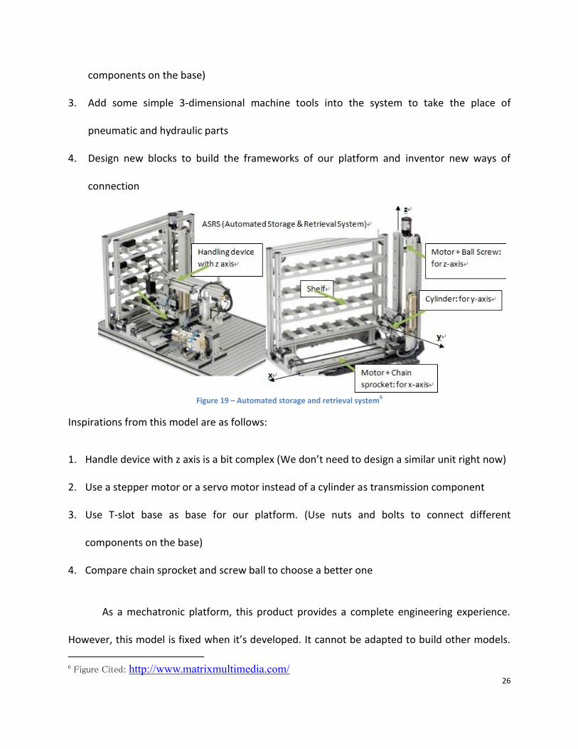
3. Add some simple 3-dimensional machine tools into the system to take the place of
pneumatic and hydraulic parts
4. Design new blocks to build the frameworks of our platform and inventor new ways of
connection
Figure 19 – Automated storage and retrieval system
6
Inspirations from this model are as follows:
1. Handle device with z axis is a bit complex (We don’t need to design a similar unit right now)
2. Use a stepper motor or a servo motor instead of a cylinder as transmission component
3. Use T-slot base as base for our platform. (Use nuts and bolts to connect different
components on the base)
4. Compare chain sprocket and screw ball to choose a better one
As a mechatronic platform, this product provides a complete engineering experience.
However, this model is fixed when it’s developed. It cannot be adapted to build other models.
6 Figure Cited: http://www.matrixmultimedia.com/

27
The re-configurability of this platform needs to be improved. At the same time, the whole
system focus more on the mechanical structure, more electrical components can be added to
provide a multi-disciplinary experience.
2.4 Our idea of reconfigurable logistics platform
After the research of all the products in the market, we gradually come up with our own
solution for building a reconfigurable and multi-disciplinary platform. There are some devices
listed in the project description for reference purposes: XY plotter, robot moving car with
positioning function, inverted pendulum. We had several discussions and tried to find common
ground among them. Except for realizing these functions on the platform, we intend to add
some functions imitating the work of logistics. Such as: goods delivery, detection and screening,
loading and unloading work, warehouse storage transportation, positioning and handling of
container.
Figure 20 – Two types of cubic warehouse models
In the platform, the main components are listed as follows:
- Power components: steering engine (finite angle type and continuous rotating type),
stepper motor, DC motor (with encoder), Servo.
- Transmission parts: conveyer belts, ball screw rod.

28
- The operative part: electromagnet, translational pincer, push rod.
- Sensor: encoder, encoder, strain gauge force sensor, infrared sensor, eddy current
sensors, color recognition sensors
Figure 21 – Examples of module family7
2.5 Electrical part research
2.5.1 LEGO Mindstorms
LEGO Mindstorms is a product developed by the world renowned company LEGO. It is a
modular building block system that provides a great development environment for users
ranging in all ages. It is a robust system with mechanical hardware ranging from basic blocks to
complex motors. As far as LEGO’s electrical hardware includes various sensors, a 32-bit Arm 7, a
Bluetooth and a USB interface. Furthermore the LEGO Mindstorms series also has a user
friendly drag drop graphical user interface (GUI) with the ability to connect to well-known
engineering software like LabVIEW.
7 Figure Cited: http://www.depush.com/

29
2.5.2 ROBO TX Training Lab
ROBO TX Training Lab is a FischerTechnik product that is similar to the LEGO Mindstorm
system. It is also a robust modular building block system. Its mechanical hardware ranges from
various linkage systems to complex motors. As far as the electrical hardware is concerned the
Lab kit contains various sensors, a 32-bit Arm, USB and Bluetooth interfaces. Its software is also
like LEGO. This lab kit has user-friendly GUI with a flow chart like setup.
2.5.3 VEX Robotic Design System
VEX is a robust modular, building block, prototyping system. It is commonly used in most
high school and college programs. It has a wide array of mechanical hardware which includes
gears, rails servos, and motors. As far as the electrical hardware the VEX platforms contains a
standard PIC microcontroller with wireless receivers/ transmitters, microchip processor, digital
input/output (I/O), analog in, interrupts (I/O), serial ports and an array of sensors. Its software
contains a modular drag-and-drop GUI that can use Easy C, RobotC, or Mplab. Furthermore it is
able to interface with other engineering software. Unlike LEGO Mindstorms and the ROBO TX
Training Lab, the VEX system contains more metallic parts.
2.6 Technologies used in mechatronic platform
After the research on the existing mechatronic products, the research on computing
technologies and control system will be necessary.
2.6.1 Microcontrollers
A microcontroller is a small computer on a single integrated circuit chip. It usually
contains a processors core ranging from 4-bit to 64-bit, memory including RAM, ROM, EPROM,

30
EEPROM, flash, and programmable input/output peripherals such as timers, PWM generator,
UART, I2C, SPI etc.
MSP430: The MSP 430 platform is a family of mix-signal 16-bit RISC microcontrollers from Texas
Instruments. It provides solutions for low-cost, low-power consumption embedded applications.
Its low-power architecture, which combined with five low power modes, is optimized to achieve
extended battery life through disabling unneeded clocks and CPU. This type of microcontroller is
typically suited for battery power devices. The top CPU speed is 25MHz8. The device provides
access to usual peripheral options: internal oscillator, timer including pulse-width-modulation
and watchdog, USART, SPI, I2C, 10-16 bit Analog-to-Digital converters, and brownout reset
circuitry; It also includes some less usual peripheral options: comparators, on-chip op-amp for
signal conditioning, Digital-to-Analog Converters, LCD driver, hardware multiplier, and USB etc.
ARM7TDMI Based microcontroller (AT91SAM): ARM is the industry's leading provider of 32-bit
embedded microprocessors/microcontroller. It offers a wide range of processors based on RISC
instruction set architecture developed by ARM Holdings that deliver high performance, industry
leading power efficiency, and reduced system cost. AT91SAM are a family of Atmel chips based
on the 32-bit RISC microprocessors from ARM. These chips can be targeted as microcontroller
since they can include embedded flash and memory, a DMA controller that allows control of a
number of peripherals such as USB, SPI, UART, and ADC, and standard communications and
networking interfaces such as CAN, Ethernet.
ATMEL AVR: The AVR 8-bit/32-bit chip family deliver high performance, high power efficiency,
8 http://en.wikipedia.org/wiki/TI_MSP430#cite_note-0

31
and high design flexibility. They are based on the industry's most code-efficient architecture for
C and assembly languages. The AVRs offer a wide range of features such as multifunction, bi-
directional general purpose I/O ports with built-in pull-up resistors, multiple internal oscillators,
internal EEPROM, timers, pulse-width-modulation output, analog-to-digital converters, serial
interfaces including I2C, USART, SPI, CAN support, USB support etc.
From a brief description of the current state-of-art microcontroller technologies and
commonly used microcontroller, the team found that the microcontrollers were so powerful
today. It provides standard and commonly used interfaces with low power consumption. The
choice of a microcontroller will be based on the controls needed in the design. The choice of the
microcontroller for the mechanical system will be discussed later in the result chapter.
2.6.2 Motor control system
A motor control system consists of a set of motor controllers that serves to govern
several electric motors in some predetermined manner. A motor controller can use a manual or
automatic means for starting and stopping the motor, selecting rotation directions, regulating
speed or torque, and protecting against overloads and faults.
2.6.2.1 Servo controller (brushed DC motor, brushless DC motor, AC servo motor)
Servo controllers use close-loop control to provide precise position control. This is
commonly implemented with encoders, or magnetic sensors to directly measure the rotor's
position. Or the servo motor may be controlled by microcontroller with pulse-width
modulation. This type of controller can provide precise position control, fast acceleration rate,
and precise speed control.

32
2.6.2.2 Stepper motor and Stepper motor controller
Stepper motor is a commonly used component in mechatronic systems. A stepper motor is a
brushless, electric motor that can divide a full rotation into a large number of steps. Stepper motors
operate differently from DC brush motors, which rotate when voltage is applied to their terminals.
Stepper motors, on the other hand, effectively have multiple "toothed" electromagnets arranged
around a central gear-shaped piece of iron. The electromagnets are energized by an external control
circuit, such as a microcontroller. To make the motor shaft turn, first, one electromagnet is given power,
which makes the gear's teeth magnetically attracted to the electromagnet's teeth. When the gear's
teeth are aligned to the first electromagnet, they are slightly offset from the next electromagnet. So
when the next electromagnet is turned on and the first is turned off, the gear rotates slightly to align
with the next one. From there the process is repeated. Each of those slight rotations is called a "step",
with an integer number of steps making a full rotation. In that way, the motor can be turned by a precise
angle.
Stepper motor controllers are usually done in open loop, which is assumed that the rotor
position follows a controlled rotating field. This type of controller provides much higher voltages to drive
the motors, and limit current through pulse-width modulation. The usual configuration of this type of
controller is to have a positioning controller that sends step and direction pulses to a separate higher
voltage driver which is responsible for communication and current limiting with the motors.
2.4.2.3 DC motor controller
DC motors are most common drive components in a mechatronic platform. DC motors
are usually controlled by using a set of transistors and switches to create a circuit called “H-
bridge”. The H-bridge can be model as four switches (usually two pnp and two npn transistors)
with a voltmeter that determines the on-off behavior of four switches. Each switches on-off
combination determines the state of the motor movement. The model of an H bridge circuit is

33
shown in figure 2 below9.
Figure 22 – DC motor controller
2.6.3 Sensors
Sensors are devices that receive signals and convert those signals into quantities that
can be read by an instrument. A good sensor should be sensitive to the measured property and
insensitive to any other properties. Ideal sensors are designed to be linear to be able to convert
to useful information by using linear functions.
Infrared proximity sensor: Infrared proximity sensor (detector) is used for computing the
distance to any nearby objects. The sensor sends out a beam of IR light, and then used the
characteristics of reflected IR signal. The type of sensor usually has a predefined range of
distance detection.
Tactile sensor: A tactile sensor is a transducer that is sensitive to touch, force, or pressure. This
type of sensor will measure and register the interactions between a contact surface and the
environment.
Ultrasonic sensor: Ultrasonic sensors are usually transceivers that both send and receive signals.
They usually generate high frequency sound waves and evaluate attributes of a target by
interpreting the echoes from radio or sound.
9 http://en.wikipedia.org/wiki/H-bridge

34
Hall Effect magnetic sensor: Hall Effect magnetic sensors are the most common magnetic
sensing device. These sensors produce a voltage proportional to the applied magnetic field.
Sensors are very important in Robotics and automated system design. The sensitivity and
insensitivity of a sensor are both affecting sensors' performance. Sensors with high precision
can be very expensive, but cheap sensors can be affecting the design significantly.
2.6.4 Communication
Communication is an important topic in mechatronic system since it is the method that allows
user to control the mechatronic system.
Controller area network (CAN): CAN is a message-based protocol used in automotive
applications. It allows microcontroller and devices to communicate with each other within a
vehicle without a host computer. This is a typical protocol often used in robots.
Infrared: Infrared is often used in TVs’ remote control. Using infrared on a robot is easy and
cheap, but it has a line-of-sight limitation.
Radio frequency (RF): Radio frequency is a rate of oscillation in the range of about 3 kHz to 300
GHz, which corresponds to the frequency of radio signals. There are complete RF modules
available these days which can be connected to a robot without much extra components. RF
doesn’t have a line-of-sight limitation, but it is more expensive than Infrared.
Bluetooth: Bluetooth is an open wireless standard for exchanging data over short distances
using short wavelength radio.

35
2.7 Upper PC interface development environment research
2.7.1 LabVIEW vs. C language for Control system user interface design
According to our research and suggestions from the advisor, we have 2 options for the
PC programming. Both LabVIEW and C language can be used to complete our project. However,
due to user friendliness of the tool and time constraint, we choose LabVIEW as our
programming tool. The following provide detailed comparison between those two options.
C language is a text-based programming language. It requires long-term development of
graphical user interface. We only have seven weeks for this project. So it may be hard to
complete the design of graphical user interface for our automatic warehouse and X-Y plotter
with C language.
LabVIEW is a graphical programming language. It is intuitive and requires short-term
development for graphical user interface. Another advantage of labview is many libraries with a
large number of functions for data acquisition, signal generation, mathematics, statistics, signal
conditioning, analysis, etc., along with numerous graphical interface elements are provided in
several LabVIEW package options. What’s more, the fully modular character of LabVIEW code
allows code re-use without modifications: as long as the data types of input and output are
consistent, two sub visual instruments are interchangeable. All these make it a good choice to
design our graphical user interface with labview instead of C language.
2.7.2 LabView features consideration
LabVIEW is a platform and development environment for a visual programming language
from National Instruments. It is commonly used for data acquisition, instrument control, and
industrial automation on a variety of platforms. The purpose of such programming is

36
automating the usage of processing and measuring equipment in any laboratory setup.
The image below is an illustration of a simple LabVIEW program showing the dataflow
source code in the form of the block diagram in the lower left frame and the input and output
variables as graphical objects in the upper right frame. The two are the essential components of
a LabVIEW program referred to as a Virtual Instrument.
Figure 23 - LabVIEW front panel and block diagram
Benefits of using LabView as a programming language includes the following six aspects:
Interfacing, Code compilation, large libraries, Code re-use, Parallel Programming, User community.
Inevitably, Labview has its own disadvantages in application. Unlike common programming languages
such as C or FORTRAN, LabVIEW is not managed or specified by a third party standards committee such
as ANSI, IEEE, ISO, etc. This leads to inconvenience in licensing, runtime environment, and formal testing.
After considering all the benefits and disadvantages of the Labview, we come to the conclusion that
Labview is the most suitable programming tool for building our platform. It ensures the success of
completing our project.

37
3. Methodology In the methodology chapter, the flow chart, the functional block for the whole system, the
techniques used to achieve the objective and plan for the whole design process will be
discussed.
3.1 Flow chart for overall system design
In order to construct a system that satisfies the requirement of our project as well as
reaching the highest efficiency and value as possible, we comply with the following flowchart in
our whole design process.
Start
Define Parameters
Choose components
Compare and evaluate options
Draw functional block diagram
Design circuits and mechanical system
Modification and
Adjustment
Confirm design and start prototyping
Debugging
Test and evaluate design
END
Understand needs
Figure 24 – Flow chart of design process
For the detailed design of each function, we adopt the permutation and combination

38
method. When faced with a specific task of the whole system, we try to define the overall
function and divide it into several sub-functions. For each sub-function, there are several
optional designs. When these options are combined with each other, we get all the possible
solutions. The best one is chosen after comparison, so that we get the optimized final design.
Figure 25 – Flow chart for detail function design
3.2 Functional diagram of the overall system
This educational platform aims to provide multi-disciplinary learning experience for the
engineering students. The following diagram shows each block’s respective functions and their
interrelationships.

39
Electrical SystemControl Interface
Data processing and transmission
Upper PC ControlUser Interface
Data storage and transmission
Mechanical SystemFunctions realization
Mechanical transmission
InstructionsStatus
feedback
Control signal
Sensor feedback
Figure 26 – Functional block diagram of the overall system
In the background chapter, we mentioned that automatic warehouse would be the main
model we build. In order to better understand the transformation rules linking inputs and
outputs, we use the black box method to investigate the warehouse without knowledge or
assumptions about its internal make-up.
This diagram shows that our goal is to construct a system that can correctly handle the
storage and retrieval of goods with the given power, material and information flows. We will
follow this goal to construct the warehouse model.

40
Figure 27 Black box diagram of automatic warehouse
3.3 Techniques used to achieve the objectives
3.3.1 Design overview
In order to realize the goals described in the objectives, we mainly adopt three
techniques, including designing a flexible and stable installation scheme, modular and building-
block design, and integrating multi-disciplinary system. These techniques will be discussed in
detail in the following sections.
3.3.2 Design a flexible and stable installation scheme
Design flexible and stable connecting method, which allow several degrees of freedom
and installation options. This connecting method is of vital importance to ensure the success of
our platform. It should be easy to be adopted on all the modules and highly expandable for
future extension. We will study on the existing methods to find both the features of flexible
connection and stable connection. Then we try to combine those two features together to
develop our own effective method. In the next stage of design, we will design different modules

41
that utilize this connecting method to ensure flexible and reliable connection.
3.3.3 Modular and building-block design
Use modularization method to design different modules that fulfill independent
functions. Those modules should be highly interchangeable, so that the platform allows
students more freedom in choosing transmission methods and is convenient for future
extension.
In the modular design stage, we will develop two types of modules, which are general
purpose modules and special purpose modules. For the general purpose module, we will try to
find the similarity in engineering models and choose some frequently used functional modules
to design first at the development stage. For the special purpose modules, they are also
indispensable for building our platform. They perform certain functions in a specific model, but
can’t be adopted in other models easily. So we try to use fewer of them and keep them simple.
When those general purpose modules are combined with few other special purpose
modules, they can be built into various models which allow more choices for the engineering
students. In the modular design process, we mainly consider the functionality,
manufacturability, economical constraints, and time constraints to provide a balanced platform.
For the electrical parts, all modules will use one low-end controller. The
loading/unloading arm or panel module will use one controller, while the x-y plotter module will
use another. The low-end controller then will be controlled by a core microcontroller. To realize
the motion of mechanical parts, each module will use a motor for its own movement such as
moving forward/backward, moving up/down, and rotating. Sensors will be attached to some of
42
the modules such as the arm/panel module to interact with the environment. The
communication modules can be attached to the core microcontroller to perform upper PC
controls.
3.3.4 Multi-disciplinary design
In the whole process of design, we try to cover all the necessary areas for the mechatronic
major students. This platform includes diverse sensor applications, embedded microcontroller
control and upper PC programming to provide multi-disciplinary learning experience. This
requires a diverse and comprehensive module library in different areas of design.
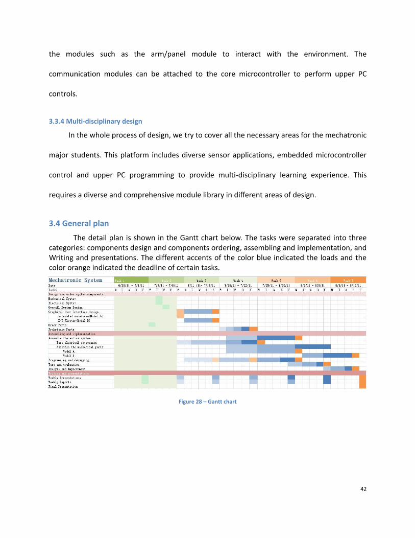
3.4 General plan
The detail plan is shown in the Gantt chart below. The tasks were separated into three categories: components design and components ordering, assembling and implementation, and Writing and presentations. The different accents of the color blue indicated the loads and the color orange indicated the deadline of certain tasks.
Figure 28 – Gantt chart

43
4. Results In this chapter, the mechanical, electrical result, and graphical user interfaces of models will be
discussed.
4.1 Results of the mechanical part
4.1.1 Design the connecting method
For a mechanical engineering educational platform, there are many practical restrictions.
For example, external force and deformation happens in the practical project as well as
experimental platform. Thus, stable connection is required in building the platform. This leads
to the contradiction between stability and flexibility.
One example we can learn from is the building blocks created by the Lego toy company.
The reason why the building blocks product is so successful and can allow various combinations

44
is that it creates a unique connection method-the convex and concave connection (shown in
the picture below).
Figure 29 – LEGO’s building blocks10
Here we have two optional designs. Option A is Lego’s convex-concave connection
method. Option B is to use aluminum frame with T-groove to connect different modules. Both
options are flexible connection method. However, option A is only useful for plastics. It can’t
provide reliable connection for metal components and bear large external force without large
deformation. Option B on the other hand uses screws to install modules on the T-groove. This
method allows for both flexibility and reliability, and is most suitable for our platform.
Our design is to use aluminum with T-groove on four sides as framework and design
standard installation holes on each module. In this way, different modules can be installed on
anywhere with a T-groove.
10 Figure Cited: http://www.lego.com/en-us/Default.aspx

45
Figure 30 – Framework and connecting method
4.1.2 Design various general purpose modules In order to ensure the re-configurability of our platform, we designed some general
modules that fulfill independent general functions in the real engineering projects. Those
general functional modules include linear motion module, conveyor belt module, pneumatic
actuating module, valves and pipe junctions. Students can use these modules to build up their
own mechatronic models just like playing with building blocks.

46
Figure 31 – Quantity of different modules used in the platform
All the modules we design obey one rule we discussed in the previous section. They
share the same standard installation holes. As long as the modules have the same function,
they are interchangeable. This rule also facilitates future expansion of the platform. As long as
the new modules obey the rule, they are compatible with the whole model.
47
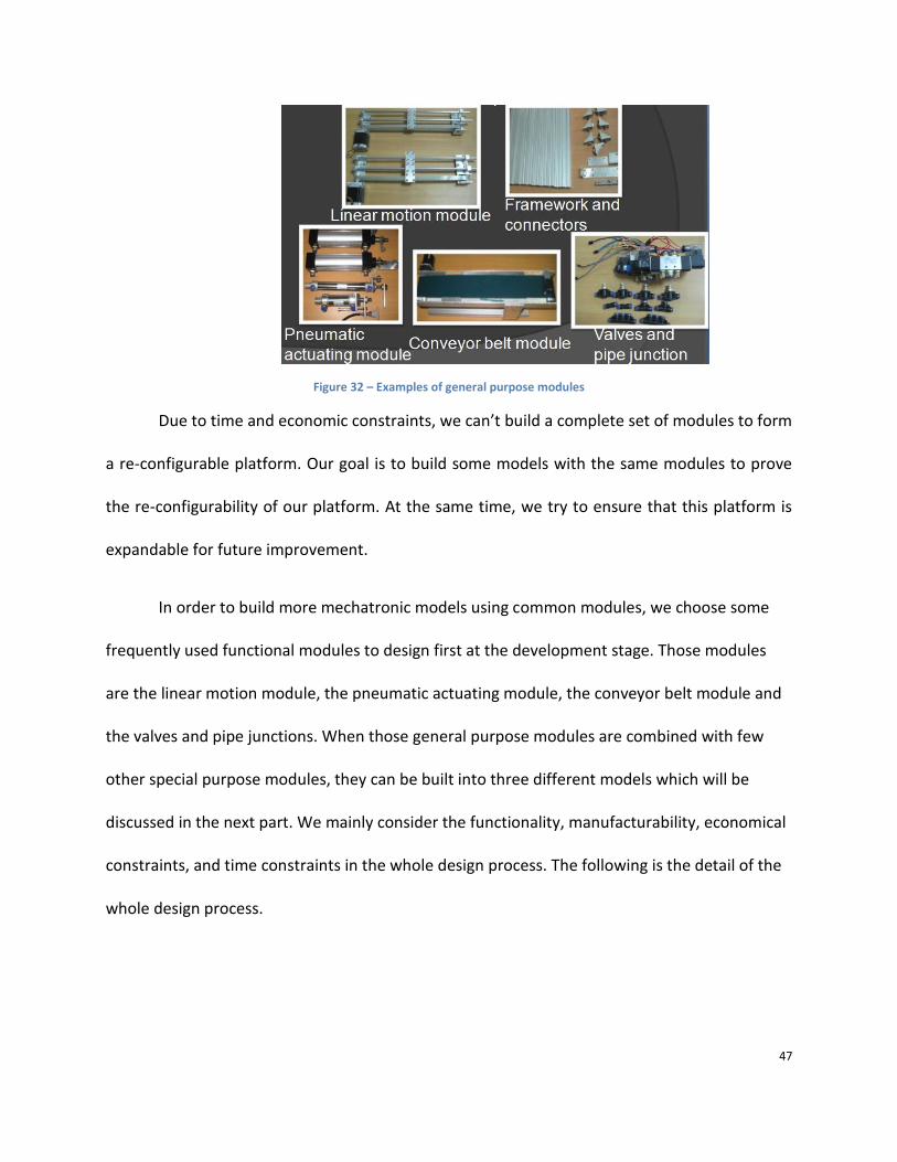
Figure 32 – Examples of general purpose modules
Due to time and economic constraints, we can’t build a complete set of modules to form
a re-configurable platform. Our goal is to build some models with the same modules to prove
the re-configurability of our platform. At the same time, we try to ensure that this platform is
expandable for future improvement.
In order to build more mechatronic models using common modules, we choose some
frequently used functional modules to design first at the development stage. Those modules
are the linear motion module, the pneumatic actuating module, the conveyor belt module and
the valves and pipe junctions. When those general purpose modules are combined with few
other special purpose modules, they can be built into three different models which will be
discussed in the next part. We mainly consider the functionality, manufacturability, economical
constraints, and time constraints in the whole design process. The following is the detail of the
whole design process.

48
4.1.2.1 Design linear motion module Linear transmission is widely used in the mechanical engineering projects. It can fulfill
various functions in the model. For example, it can transport goods at XYZ directions. It is an
important module to illustrate basic mechanical transmission knowledge.
Due to time and budget constraint, we can only build one linear module in our model
this summer. There are two options for consideration. They are synchronous belt proposal and
screw rod proposal. Synchronous belt is a combination of gear and belt, which means that it
can realize accurate and long distance transmission at the same time. Screw rod uses screw and
nut to convert rotation into linear motion. It ensures delicate and heavy load transmission.
Figure 33 – Two options for linear motion module
Our final decision is to use the synchronous belt. Here we list all the benefits of choosing
synchronous belt over screw rod:
- Low speed requirement for the stepper motor (screw rod requires 3000r/min, while
synchronous belt requires 300r/min)
- Cheaper (synchronous belt only requires half the price)
- Precise transmission for light load

49
4.1.2.2 Design pneumatic actuating module In the process of transporting goods from the conveyor belt to the table, we need
altogether 3 directions movement. If we use gear and rack to fulfill this function, it will be over-
complicated. However, if we use pneumatic cylinder, the problem is quite easy to solve. All we
need is three cylinders to realize storing and retrieval the goods from the shelf. The details of
the advantages of pneumatic system will be discussed in the next section.
The pneumatic cylinder has only two accurate positions, that’s beginning and ending
position. And the stroke for every cylinder is fixed. The force that can be provided by the
cylinder is determined by its diameter and air pressure. In order to meet different working
requirements, we choose three types of cylinders. And they are also designed according to the
connecting method we came up in previous section to ensure that they are compatible with the
whole system. On the rod of the cylinders, different plates can be installed to fulfill different
functions. The following picture shows the pneumatic cylinder modules we design for the
platform.

50
Figure 34 – Pneumatic actuating modules
4.1.2.3 Design conveyor belt module A conveyor belt (or belt conveyor) consists of two or more pulleys, with a continuous
loop of material - the conveyor belt - that rotates about them. One or both of the pulleys are
powered, moving the belt and the material on the belt forward. The powered pulley is called
the drive pulley while the unpowered pulley is called the idler.
The conveyor belt is widely used in real life engineering project. Building such a module
is necessary for our platform to imitate the warehouse’s function of transporting goods. In the
design of conveyor belt we have two options. One is to buy the product of MISUMI factory. The
other is to buy only the two pulleys and belt, then design our own conveyor belt. The product
of MISUMI uses complicated transmission method which includes angle gear and synchronous
belt. This ensures heavy load capacity and stable performance. But it also leads to high price
and waste in building educational platform. So we decide to buy only some necessary
components and build our own simpler conveyor belt.

51
Figure 35 – Two options for conveyor belt module
In order to enhance the load capacity of the conveyor belt, we add rose work at the
power pulley to increase friction force which provides power for the transportation process. At
the ending part of the conveyor belt, we will use a pneumatic cylinder to push onto the belt.
That means the belt will stand external force from the vertical direction. So we also add
supporting plate at the necessary position to enhance its stability. The newly designed conveyor

52
belt is simpler, thus cheaper than the existing product. Also the modification we added to the
conveyor belt design helps it better fit into our platform.
4.1.2.4 Design valves and pipe junctions The speed of the cylinder is determined by the diameter and air pressure. Once
manufactured, the diameter of the cylinder cannot be changed. So we need to adjust the air
pressure to control the speed of the cylinder. Also, the moving direction of the cylinder is
determined by the flow of compressed air. So we include directional valves and throttle valve
modules into the platform. These valves help us better control the kinematic parameters of the
system.
Figure 36 – Valves and pipe junction modules
Another feature of the valves and pipe junctions is that they all have standard
connecting ports. All the ports are supposed to be connected with pipe with 8 mm diameter.
These specially designed ports can be easily connected or disconnected with the pipes. This
feature ensures highly flexibility in building various pneumatic circuits as desired. Also the two
ports, three ports and five ports pipe junctions allows highly free extension of air circuits. These
pneumatic modules provide the possibility of building any circuit the students want.

53
4.1.3 Build models and design special purpose modules
In order to prove the re-configurability of platform and include multi-disciplinary
education purpose into it, we decide to build some models using the modules. Those models
should include the educational purpose put forward by our sponsor and also have common
features to be easily built. The final design result is three educational mechatronic platforms. As
show in the picture below, model A is an automatic warehouse, model B is an X-Y plotter,
model C is another version of cubic warehouse.
Figure 37 – Three different models in our platform
We design those models because they include knowledge about sensor signal obtain,
motor drive, mechanical transmission, microcontroller programming, PC programming and so
on. The models are composed of MCU Control Card, Stepping Motor, small threaded shaft and
Sensors.
More importantly, in order to build up those three models, we use many common
modules. For each model, we need only include few special purpose modules. The following
Venn diagram shows the quantity of modules we use in the three models. The large amount of
overlapped part proves the re-configurability of our platform.

54
Figure 38 – Venn diagram of number of modules
The following is the detail of the whole design process of the 3 models and corresponding special purpose modules.
4.1.3.1 Model A – Automated Warehouse An automated storage and retrieval system (ASRS or AS/RS) consists of a variety of
computer-controlled methods for automatically placing and retrieving loads from specific
storage locations. Automated Storage and Retrieval Systems (AS/RS) are typically used in
applications where: there is a very high volume of loads being moved into and out of storage.
Nowadays, automatic warehouse is widely used in the industry. Our goal is to connect
engineering education with real life engineering experience. So we decided to build a model of
automatic warehouse, which has functions like goods delivery, detection and screening, loading
and unloading work, warehouse storage transportation, positioning and handling of container.
Due to the time constraint of our project, the sponsor suggests us to focus our attention on
building the automatic warehouse. If this model is successful, then we carry on with other
models. So we try to include most of the educational functions into the model. Here are our
original ideas for building such a warehouse, altogether four options. After consider the time
factor and difficulty of the development process, we choose option A as our main target.

55
Figure 39 – Original ideas for MODEL A
In the warehouse model, we use the general purpose module such as, the linear motion
module, conveyor belt module, and pneumatic cylinder modules and so on. But those module
alone cannot form the warehouse model, more special purpose modules should be include to
build a complete model. The figure 40 shows some special purpose modules we designed for
the automatic warehouse, including the goods model, vacuum cup, and so on.

56
Figure 40 – Special purpose modules
4.1.3.2 Design pneumatic schematics for Model A
There are many different ways to realize the function of linear motion. For example,
crank block mechanism, screw rod, transmission belt, gear and track transmission. Those
transmission methods require complicated mechanical structure and control method.
Compared with those options, pneumatic transmission saves quite lot of effort. It has a simple
power and transmission part, and is easy to control. No electrical motors or gears are involved
in the whole system; the power is supplied by the compressed air; control system is made up of
simple relays. In this model, our requirement is that goods position is accurate at the beginning
and ending position. No specific requirement for speed and position control during the
transposition. That’s to say, pneumatic system can perfectly serve our purpose. If we use mini-
pneumatic components is the platform, the whole pneumatic system cost only about 1000
Yuan. At the same time, students can learn about the functionality and performance of
pneumatic components with firsthand experience.

57
In order to build up a complete pneumatic system, a pneumatic schematic is needed at
first. The skill of designing pneumatic schematic to serve special purpose is also required by the
courses of pneumatic transmission. In the warehouse model, there are totally 4 cylinders and 1
vacuum cup needed. In order to provide enough air pressure and ensure precise motion of the
pneumatic components, a pneumatic schematic is built as follows. An air compressor, triple
piece, pressure gauge, throttle valves, electromagnetic directional valve are needed to form a
complete pneumatic system as well as provide safety protection, and adjustment.
Figure 41 – Pneumatic schematics for the warehouse

58
4.1.3.3 Design special purpose modules –goods module design
In the automated warehouse model, goods are needed to perform the functions of the
warehouse. There are two options, one is square, and another is round. Both of them can fulfill
the function we need. However, their manufacturability has a great difference. Square goods
manufacturing method is milling and the round one is lathe. That’s to say, round shape can cut
down the price by 75 percent. However, if the goods model is supposed to be manufactured for
large scale in the near future, both designs can be adopted.
Figure 42 – Two options for goods design
Another problem with the goods design is its material. Aluminum and Nylon are two
optional choices. The criterion to make a decision is that the goods can be easily picked up by
the vacuum cup and steadily transported by the air cylinder. Later experiment shows that
aluminum surface is smoother and can be better picked up by the vacuum cup. But it’s much
heavier than nylon and falls down easily during the transportation. Air cylinder’s motion is not
constant motion with slight impacts. Lighter weight is an advantage for steady transportation.
Nylon material on the other hand can also be easily picked up and steadily transported from
one place to another. Considering all the factors above, the final goods design is round shape
goods made of nylon.
Final design
Detail components
design

59
Figure 43 – Two optional materials for goods design
4.1.3.4 Design special purpose modules –goods table and brace
As is mentioned before, air cylinder’s motion is not constant with impacts at the
beginning and ending of the stroke. Due to the pneumatic characteristic of air cylinder, special
goods table should be designed to ensure its stability during the transportation. We make a
groove under the goods model, and a slope at the table below. There is also 2mm tolerance
between the groove and the model to allow for positioning error. This tolerance together with
the slope ensures stable transportation.
Figure 44 – Explored view of the transportation table
4.1.3.5 Design special purpose modules –vacuum cup
The transportation of goods from one place to another requires vacuum cup. Vacuum
can be generated in two ways that is vacuum generator and vacuum convertor. In this model

60
we only need one vacuum cup, so it’s not necessary to buy a vacuum generator. Use vacuum
convertor to convert compressed air into vacuum is much more economical and convenient.
According to the data in the pressure and vacuity curve, the existing air compressor can provide
enough vacuum for our whole model.
Figure 45 – Working principle for vacuum generator
We have shown that vacuum cup is feasible in our platform. The next step is to
determine its parameter and control method. The vacuum cup’s size is determined by the
weight and shape of the goods model. Calculation shows that vacuum cup with diameter of
40mm and height of 60mm is suitable for our platform. For the control method, vacuum can be
controlled by the valves circuit. When compressed air or vacuum comes out of the cup, the cup
can either pick up or drop the goods. It’s quite easy to be controlled to perform the desired
functions.
4.1.3.6 Build model B – X-Y plotter
An X–Y plotter is a plotter that operates in two axes of motion ("X" and "Y") in order to
draw continuous vector graphics. The term was used to differentiate it from standard plotters
which had control only of the "y" axis, the "x" axis being continuously fed to provide a plot of
some variable with time. Plotters differ from Inkjet and Laser printers in that a plotter draws a

61
continuous line, much like a pen on paper, while inkjet and laser printers use a very fine matrix
of dots to form image.
The X-Y plotter is adopted into engineering education, because it is simple and covers
most knowledge required of mechatronic major students. Our re-configurable platform can be
used to build an X-Y plotter with the same general purpose modules mentioned in model A. We
also need to include some special purpose modules to make the model complete. The following
is the detail of the design for the model and special purpose modules.
In the X-Y plotter, we use the aluminum frame to support the whole system. Use two
linear motion modules to execute the positioning of the pen. A pneumatic cylinder is used to lift
and drop the pen. All these modules are the same modules used in the previous model.
There are two options of building an X-Y plotter, one is moving the pen while the table is
fixed; the other is moving the table while the pen is fixed. In our model, the pen is installed on a
pneumatic cylinder and it’s at a high position. So we choose the strategy of moving the table
and fix the pen to ensure stable and accurate motion control. At the same time, the writing
table is made of light material - organic glass, which further improves the condition of our
platform.
For the special purpose modules, we designed a pen holder and writing table. Previously
the pen is directly connected to the cylinder’s rod, which leads to a serious problem. The shaft
of the pneumatic cylinder will rotate under external force. If the problem is not solved, the
positioning of the pen will be accurate in the writing process. In order to solve this problem, we

62
modify the connectors and add guiding shaft for the plotter. Later test of the whole system also
proves the success of this design.
Figure 46 – Design options for pen holder
4.1.3.7 Build model C – cubic warehouse
A warehouse is a commercial building for storage of goods. Warehouses are
usedbymanufacturers,importers,exporters,wholesalers,transportbusinesses, customs, etc. They
are usually large plain buildings in industrial areas of cities and towns. They usually have loading
docks to load and unload goods from trucks. Sometimes warehouses are designed for the
loading and unloading of goods directly from railways, airports, or seaports. They often
have cranes and forklifts for moving goods, which are usually placed
on ISO standard pallets loaded into racks. Some of the most common warehouse storage
systems are:
Pallet rack including selective, drive-in, drive-thru, double-deep, pushback, and gravity
flow; Mezzanine including structural, roll formed, racks; Horizontal Carousels; Vertical Carousels
Model A is an example of Vertical Carousels. That’s to say its transportation axis is
placed vertically. Model C is another version of warehouse, its main difference from model A is
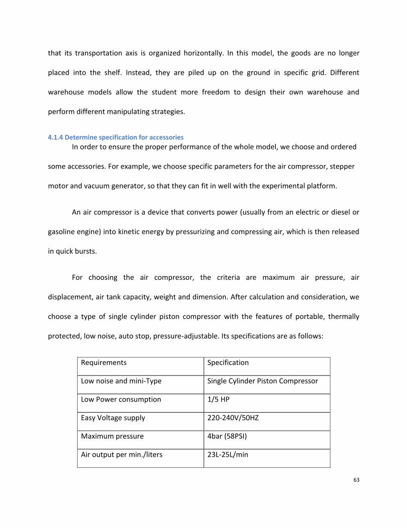
63
that its transportation axis is organized horizontally. In this model, the goods are no longer
placed into the shelf. Instead, they are piled up on the ground in specific grid. Different
warehouse models allow the student more freedom to design their own warehouse and
perform different manipulating strategies.
4.1.4 Determine specification for accessories
In order to ensure the proper performance of the whole model, we choose and ordered
some accessories. For example, we choose specific parameters for the air compressor, stepper
motor and vacuum generator, so that they can fit in well with the experimental platform.
An air compressor is a device that converts power (usually from an electric or diesel or
gasoline engine) into kinetic energy by pressurizing and compressing air, which is then released
in quick bursts.
For choosing the air compressor, the criteria are maximum air pressure, air
displacement, air tank capacity, weight and dimension. After calculation and consideration, we
choose a type of single cylinder piston compressor with the features of portable, thermally
protected, low noise, auto stop, pressure-adjustable. Its specifications are as follows:
Requirements Specification
Low noise and mini-Type Single Cylinder Piston Compressor
Low Power consumption 1/5 HP
Easy Voltage supply 220-240V/50HZ
Maximum pressure 4bar (58PSI)
Air output per min./liters 23L-25L/min

64
Auto stop function (special pressure
available)
start at 42 psi, stop at 58 psi
Fitting available manometer; air filter; pressure
regulator
Connections with connection 1/8" BSP
Small Net Weight 3.6KG
Mini-Dimension 245 x 135 x 170mm
Table 6 – Air compressor specification
Vacuum Generators use compressed air to generate vacuum using a venture. Vacuum
levels down to -25 inHG (-85kPa) is obtained from single and multi-stage units with suction flow
greater than 7 SCFM (200 l/min.) SMC's vacuum generators can be connected via a manifold or
used individually. These compact devices can also be customized to integrate suction filters,
vacuum switches, and supply/release valves onto the generator.
In the whole model we need only one vacuum cup, its workload is only 100g at a time.
In order to ensure stable transportation of the goods model, we choose ZH07BS060601 vacuum
generator which has ten times greater capacity than required. The picture below shows the
pneumatic schematic of using vacuum generator to provide vacuum for the vacuum cup.
Figure 47 – Vacuum cup schematic

65
4.1.5 Complete 2D drawings and manufacturing
After the design of all the modules and models, we finished 2D drawings for all the
connectors and arranged manufacturing. In order to allow for certain modification according to
the performance of the connectors, we divide the manufacturing into three steps according to
their inter-relationship. During the manufacturing step, we contact the factory to discuss the
manufacture ability, and make certain modification. Also, we report to the sponsor to keep
them aware of our progress and budget. In the end, we manufactured altogether 37 kinds of
components, and finished the project on time. All the 2D drawings for the project are in the
attachment.
4.1.6 Real Model A assembling and Model B re-assembling
After the manufacturing and ordering process, we get all the components ready for
building the whole platform. The first step is assembling all the modules according to their
respective functionalities. The second step is assembling model A – automatic warehouse based
on the modules we have. In order to ensure the correct position relations between different
modules, this process requires careful calculation, measurement, and testing. The final result of
model A is show in the photo below. Final assembly proves that the original design is successful.
However, testing with the control system and further improvement is needed to make it more
complete.

66
Figure 48 – Final assembly of Model A
The following table shows the main general purpose modules and special purpose
modules used in the automatic warehouse.
Module name Quantity Type
Linear motion module 2 General purpose
Conveyor belt module 1 General purpose
Pneumatic cylinder module 4 General purpose
Vacuum cup module 1 General purpose
Linear guide module 2 General purpose
Aluminum frameworks 10+3 General purpose
Goods model 10 Special purpose
Goods brace 20 Special purpose
Goods table 1 Special purpose

67
Table 7 – Modules used in automated warehouse
The third step is to disassemble model A and re-assemble it into model B – X-Y plotter.
In the disassemble process, we only disassemble model A into modular level. Then we combine
the general purpose modules with some special purpose modules to build the new model. The
disassembling and re- assembling process only consumes one day, this also proves the highly
re-configurability of our platform. The picture below is the result of X-Y plotter.
Figure 49 – Final assembly of X-Y plotter
The following shows the quantity of main general purpose modules and special purpose
modules used in the X-Y plotter.

68
Module name Quantity Type
Linear motion module 2 General Purpose
Pneumatic cylinder module 1 General Purpose
Linear guide module 2 General Purpose
Aluminum framework 4+1 General Purpose
Pen holder module 1 Special Purpose
Writing table 1 Special Purpose
Table 8 – Modules used in X-Y Plotter
4.1.7 Summary for mechanical part
We successfully came up with the connecting method that was both flexible and stable,
and adopt it in the design of general purpose modules and special purpose modules. This
method helped us to make the re-configurable mechatronic training system possible. Later
practice also proves that our design is feasible in the development of a re-configurable
mechatronic training system.
We found and designed some general purpose modules that are most frequently used
in the existing educational platforms. Together with some special purpose modules, those
modules can be used to build different mechatronic models. We select 3 real life engineering
models as examples to prove the re-configurability of the platform. When we propose this to
the sponsors, they suggest us to finish building one of the models in the summer. As a result,
we have successfully built the automatic warehouse, as well as finished the X-Y plotter. Both
models work as expected, although with minor mistakes for future improvement. The reason
why we can finish two models at such a fast speed is that our original design is very suitable for
solving our problem. This also proves the success of our design.

69
In this newly developed platform, we help DEPUSH technology company develop a
highly reconfigurable mechatronic training system which never exist in the market. This product
contributes to competitive advantage in the educational platform market. Also, we include
pneumatic system which is never used by the company before in the educational platform. This
helps the company to build up a complete product family which covers all the educational areas
in mechanical engineering.
4.2 Results of the electrical part This part mainly discussed about the result and design process of the electrical system including
control system architecture, control system pins layout, relay driver circuit, stepper motor controller,
and sensor applications.
4.2.1 AT89C52 VS STM32F107VC
The two main considerations in selecting a microcontroller in the project are the continuity
development of Depush’s product and expendability for future design. The AT89C52 microcontroller is
commonly used in the products of Depush Technology. And STM32F107VC will be the next
microcontroller to use in their high-end products. These two options are both provided by the sponsor
for the continuity of their product development. Thus, these two microcontroller need to be compared
based on the technical needs.
Requirements Specifications
Communication between PC and microcontroller UARTx1
Obtaining information from Barcode scanner UARTx1
Two stepper motor controls I/Ox4, TIMERx1
Four pneumatic cylinder controls I/Ox8
Obtaining information from Infrared proximity sensor ADCx1 Table 9 – Requirements/Specifications
The AT89C52 is an 8-bit microcontroller and the STM32F107VC is a 32-bit microcontroller. The
comparison between them seems to be unfair, but based on the technical requirements of the entire

70
system; the microcontroller should have the specifications shown in Table 4 above. By reading the data
sheet of the AT89C52, we found that it had 32 programmable I/O lines, 3 timers, one UART interface
and no built-in ADC. With the development board provided by the sponsor, the only requirement that
the AT89C52 did not meet was it only has one UART for serial communication. Besides lacking of a UART,
it also had limited amount of resources to use for future design. Comparing to the AT89C52, the
STM32F107VC not only meet the technical requirements, but also provide extra interfaces such a multi-
channel 12-bit ADC, Ethernet, USB, etc., for future design. Thus, the STM32F107VC would be the better
option for our control system design.
4.2.2 Overall system architecture The figure 50 shows the top level view of the overall system architecture. The microcontroller
(STM32F107VC) is the control core of both the automatic warehouse and the x-y plotter. Based on the
information collected from the host computer, the infrared sensor, and the barcode scanner, the
microcontroller would handle information transmission, pneumatic component control, and motor
control.
Figure 50 – Overall system architecture
For the automatic warehouse, the control system's main task is to choose storage/ retrieval
mode according to the instruction sent by the host computer. Then it will judge which place to store or
which good to retrieve based on sensor information or instructions and control the drive components in

71
the mechatronic platform. The program flow chart of the automated warehouse (Model A) is shown in
figure 51 below. All the operations in the automated warehouse is sequential. The goods’ delivery will
start at conveyor belt with goods detection subsystem for verifying the height of the goods are within
the desired range. Then the goods will be lifted by the vacuum cup from the end the conveyor belt
when Barcode scanner is finish reading its information. Based on the information read from the barcode,
the X axis stepper and Y axis stepper will deliver the goods to the right position with the pneumatic
cylinders to push or pull the goods forward or backward respectively.
Figure 51 – Flow chart for Model A
For the x-y plotter, the control system's main task is to select the operating mode according to
the instruction sent by the host computer, to draw every letter required with a line-drawing mechanism.
The program flow chart of the x-y plotter is shown in figure 52 below.

72
Figure 52 – Flow chart for Model B
For the whole mechatronic platform, the control system’s main task is to combine the function
modules in each model and ensures they work properly. The program flow chart of the whole
mechatronic platform is shown in figure 52 below.
Figure 53 – Flow chart of the overall system
4.2.3 Overall system pins layout
The table blow shows the pins and interfaces used in the development board with the core
STM32F107VC (Cortex-M3).
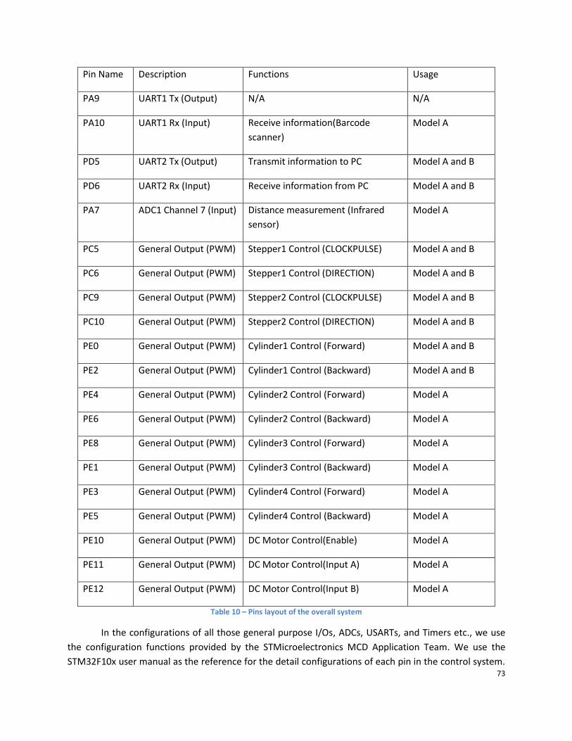
73
Pin Name Description Functions Usage
PA9 UART1 Tx (Output) N/A N/A
PA10 UART1 Rx (Input) Receive information(Barcode
scanner)
Model A
PD5 UART2 Tx (Output) Transmit information to PC Model A and B
PD6 UART2 Rx (Input) Receive information from PC Model A and B
PA7 ADC1 Channel 7 (Input) Distance measurement (Infrared
sensor)
Model A
PC5 General Output (PWM) Stepper1 Control (CLOCKPULSE) Model A and B
PC6 General Output (PWM) Stepper1 Control (DIRECTION) Model A and B
PC9 General Output (PWM) Stepper2 Control (CLOCKPULSE) Model A and B
PC10 General Output (PWM) Stepper2 Control (DIRECTION) Model A and B
PE0 General Output (PWM) Cylinder1 Control (Forward) Model A and B
PE2 General Output (PWM) Cylinder1 Control (Backward) Model A and B
PE4 General Output (PWM) Cylinder2 Control (Forward) Model A
PE6 General Output (PWM) Cylinder2 Control (Backward) Model A
PE8 General Output (PWM) Cylinder3 Control (Forward) Model A
PE1 General Output (PWM) Cylinder3 Control (Backward) Model A
PE3 General Output (PWM) Cylinder4 Control (Forward) Model A
PE5 General Output (PWM) Cylinder4 Control (Backward) Model A
PE10 General Output (PWM) DC Motor Control(Enable) Model A
PE11 General Output (PWM) DC Motor Control(Input A) Model A
PE12 General Output (PWM) DC Motor Control(Input B) Model A
Table 10 – Pins layout of the overall system
In the configurations of all those general purpose I/Os, ADCs, USARTs, and Timers etc., we use
the configuration functions provided by the STMicroelectronics MCD Application Team. We use the
STM32F10x user manual as the reference for the detail configurations of each pin in the control system.

74
Extra cares are needed in the configuration process. For example, the general purpose I/O ports can
work in several modes such as input pull-up, and input floating, etc. They also have different alternate
functions to provide such as ADC input channel, USART Rx input channel, etc. Besides the properties or
functions of the I/O ports, they have to function properly under different peripheral clocks or at
different speeds. (The detail I/O configurations can be found in the Appendix B.)
4.2.4 Relay driver circuit All pneumatic components mentioned in the mechanical section are controlled by 24V relays,
but the STM32F107VC (Cortex-M3) only outputs 3.3V signals. Thus, to control the relays, a relay driver is
needed. The simplest method is to connect the relays with a 24V power supply and use a transistor as a
switch. There are two options we could use to design the relay driver. One is using a power MOSFET and
the other is using a Bipolar Junction Transistor (BTJ). For high inrush current devices such as DC motor or
relays, the BTJ is a better choice because MOSFET have two main limitations in high current applications.
When using a MOSFET as a switch, the “ON” resistance RDS(on) is a very important factor since a high
RDS(ON) would result in large power dissipation and heat generation. Thus, a power MOSFET would be a
good choice since it generally has a very low RDS(ON), but this type of MOSFETs may not switch “ON” with
a 3.3V gate to source voltage since it has a 3V to 4V threshold voltage. The low RDS(ON) and low threshold
voltage is usually contradictory to each other in MOSFETs. Thus, the BTJ would be the better option in
this part.
The actual circuit design is shown in the figure below. An NPN BJT (2N3904) is used as the switch.
The relay is modeled as an inductor in serial with a 160 ohm resistor based on measurement. A flyback
diode is added in parallel with the load to protect the BJT from any induced back-emf in the inductor.
The 470 ohm base resistor is the key to use the BJT as the switch. We use the cutoff (“OFF” state) and
saturation (“ON” state) regions of the BJT operation. When the input signal is 0V, the EB junction of the
BJT conducts negligible current and the CB junction will be reversed biased. No current is flowing from
the collector to the emitter. The BJT is in the “OFF” state.

75
Figure 54 – Schematic of relay driver
For the saturation of the BJT, the EB junction and CB junction both have to be forward biased.
Since the emitter is tied to ground, the forward biasing of the EB junction is easy to achieve by applying
a voltage greater than 0.7V. In order to forward bias the CB junction, we need the collector current
become large enough. Assume the BJT is saturated so that VCE is 0.2V (from 2N3904 data sheet). Thus, IC
= (24V-0.2V)/160 = 149 mA. With the smallest β = 30 of the BJT (2N3904), we have IB = IC / β = 4.97mA.
This IB indicates the BJT is just on the edge of saturation. We want to force more current into the base of
BJT to have the BJT more saturated. We choose a factor of 1.1. The new base current would be IB =
1.1*4.97mA = 5.5 mA. Thus, the base resistor can be computed based on the input signal 3.3V from
microcontroller and the new base current: R2 = (3.3V – 0.65V)/5.5mA = 481Ω. And the power rating of
the base resistor can be easily computed by using P = I2*R = (5.5mA)(5.5mA)*481Ω = 0.015watts. In this
case, when the input signal is 3.3V, the BJT is in the “ON” state.
4.2.5 DC motor controller
The DC motor is driven by L298, which is a dual full-bridge driver. As shown in figure 55, the DC
motor can work in 4 states according to the 3 input control signals. The input of Ven is a periodic wave,
used for controlling the speed of DC motor while the inputs of C and D are logic signals, used for
VCC
24V
L11.0mH
R1160O
Q1
2N3904
R2
470O
D11N4007GP
InputSignal
IB
W
Ic
+

76
controlling the work state of DC motor.
Figure 55 – Schematic for DC motor controller
Pulse-width modulation is used for controlling the power output to the DC motor in order to
control its speed. Channel 3 of Timer2 in the STM32F107VC is used to generate the periodic wave with a
specific duty cycle. (This duty cycle can be adjusted in DCMotorCtrl() function based on the required
speed.) The voltage of the power supply for the DC motor is 24V. When the input of Ven is a periodic
wave with duty cycle which is 0.5, the DC motor, whose power voltage turns to 12V accordingly, rotates
at a preferred speed.
4.2.6 Stepper motor controller The interfaces of the SH2034D type stepping motor drive circuit are optically isolated, as shown
in figure 56. (CP: pulse signal input. DIR: direction of the input signal level. FREE: off-line signal)

77
Figure 56 – Signal inputs of the stepper motor controller
There are two ways to connect the stepper motor drive circuit: common anode connection and
the common cathode connection:
- Common anode connection: CP+, DIR+ and FREE+ are connected to common anode. CP is
connected to CP- with a resistor. DIR and FREE are connected the same way.
- Common cathode connection: CP-, DIR- and FREE- are connected to common anode. CP is
connected to CP+ with a resistor. DIR and FREE are connected the same way.
The common anode connection is adopted by us.
The rotation angle and speed of a stepper motor is determined by the number and the
frequency of control input clock pulse. In this platform, the rotation angle of the stepper motor requires
precise quantitative control while rotational speed control can be only qualitative.
The step angle of the stepper motor we chose is 1.8 degree. The stepper motor is assembled
with the synchronous belt. Therefore, the number of input control pulse can be calculated using the
following formula.

78
The stepper motor will rotate a step angle each time it receives one cycle of the control pulse.
Therefore, the frequency of input control pulse can be calculated using the following formula.
The input control clock pulses of the stepper motor controllers are generated from Timer2
interrupt channel 1 and 2 of the STM32F107VC. For controlling two stepper motors, the outputs of two
control signals are connected to CP and DIR input of the controller. The numbers of input control clock
pulses (steps) are counted with interrupts generated from Timer2 channel 1 and 2 respectively. The
frequency of input control pulse is determined by CCR1_Val of channel 1 and CCR2_Val of channel 2.
(The detail program can be found in Appendix B stm32f10x_it.c)
4.2.7 Sensor applications In this section, the application of the infrared proximity sensor and the barcode scanner will be
discussed. The infrared proximity sensor is a general purpose module in this mechatronic platform. It
can be used in other applications. The barcode scanner is a special purpose module. It is used specifically
in the automated warehouse model.
4.2.7.1 Goods’ Validation Subsystem Infrared proximity sensor Figure 57 shows the functional block of the automated warehouse goods’ validation subsystem.
This subsystem will verify if the goods are good for delivery based on the height of the goods. The
infrared proximity sensor (GP2D120XJ00F) will convert the height of the goods to a voltage signal. This
voltage signal will be processed by the microcontroller (ARM Cortex-M3) via built-in ADC. And based on
the voltage input, it will output a relay control signal to determine if the goods are good for delivery.
Figure 57- Functional block diagram of the goods’ validation subsystem
Infrared Proximity
SensorSTM32F107VC
Cortex-M3
ADC1 Relay Driver Circuit

79
When building this goods’ validation subsystem, we have two options for the distance
measurement device. One is the infrared proximity sensor, and the other is the ultrasonic proximity
sensor. These two types of sensors functions in a similar way. They both use “echo” for distance
measurement. Their difference is the nature of the signals they generate for measurement. The
ultrasonic sensor is usually more expensive than the infrared sensor. It is often used for long-distance
measurement and for short range measurement it has some “blind” region which could result in
improper measurement. To reduce the cost of the project and to choose a sensor with a shorter range
for more accurate measurement, the infrared proximity sensor is a better option for this part.
We tested the infrared proximity sensor before using it in the actual application to ensure the
accuracy of the measurement. We connected Pin 3 (Figure 58) to a 5V DC power supply, Pin 2 of the
sensor to ground, and Pin 1 to voltmeter to test the voltage output when the distance between an
obstacle and the sensor changes. The distance measurement setup is shown in Figure 59. This
measurement setup was based on the requirement on the sensor datasheet.
Figure 58 – Functional block of the infrared proximity senor

80
Figure 59 – Sensor measurement setup
The figure 60 below shows the result of the sensor voltage output measurement. The sensor
voltage output was not a linear function of the distance. It increased as the distance between the
obstacle and the sensor increased from 2cm to 8cm. The sensor voltage output reached its peak value
(2.65V) at 8cm. It is also worth mentioning that the voltage output is very stable at the same distance
when the obstacles are manufactured by the same material. When the distance between the obstacle
and the sensor is 5cm, the voltage output is 1.85V.
Figure 60 – Measurement result
0
0.5
1
1.5
2
2.5
3
0 2 4 6 8 10
Vo(V) vs Distance(cm)

81
The actual assembly of the infrared proximity sensor is shown in the figure 61 below. The sensor
was mounted 7cm above the conveyor belt to ensure the sensor operates at the valid region (2cm to
8cm). According to the goods’ design, the goods’ height is 2cm +/- 0.01cm. In other words, the distance
between the good and the sensor is 5cm +/- 0.01cm and the corresponding voltage output is around
1.85V. To ensure the appropriate operation of the automated warehouse, the height of goods has to be
2cm or less. The distance between the top of the good and the sensor should be 5cm or more, so the
reference distance 5cm is chosen to determine whether the good is too high or not. The voltage
reference to compared with is 1.85V when the distance is 5cm and the valid voltage range for qualified
goods is from 1.85V to 2.65V.
Figure 61 – Physical installation of the infrared proximity sensor
In order to use this voltage output signal to make a decision on whether goods are qualified or
not, there are two methods: using an analog comparator and using the built-in ADC analog watchdog in
the microcontroller as an analog comparator. The benefit of using an analog comparator is that it
simplifies the programming process because no ADC configuration is required, but this method will
82
cause two problems: it requires an extra circuit and power supply with both positive and negative
output and it is not easy to adjust when the voltage reference changes. In other words, the first method
does not provide a flexible solution when the application changes. This disadvantage does not meet the
requirement of re-configurability of our experiment platform. The built-in ADC analog watchdog can
detect if an input voltage goes outside the user-defined high or low thresholds. When the input voltage
goes outside of the thresholds, an interrupt will be generated. This feature allows user to have a flexible
solution to the problem. The built-in ADC on the STM32F107VC (Cortex-M3) is 12-bit and the voltage
reference on the ARM-based development board is 3.3V. This specific application is to set the low
threshold to be 1.85V. Thus the value set to the ADC analog watchdog low threshold register is
(1.85V/3.3V)*212= 0x08F8 in hexadecimal. The high threshold can be set to its peak value 0x0FFF in
hexadecimal. The high and low thresholds can be adjusted based on the need of application. In the
actual implementation of the goods’ detection subsystem, the actual low threshold is set to be 0x07C1
(1.6V) based on its installation position. (The detail ADC configuration and analog watchdog
configuration can be found in Appendix B)
4.2.7.2 Information Acquisition Subsystem - Barcode scanner The functional block diagram shown below is the information acquisition subsystem of the
automated warehouse. The Barcode scanner is the input of the subsystem. It obtains information from
Barcodes on the goods and transmits the data via serial communication to the microcontroller (ARM
Cortex-M3). These data then will be sent to the computer from the microcontroller for goods’ records
via serial port (Bluetooth). It will also be processed by the microcontroller for generating PWM signals
outputs to the stepper control circuit.

83
Figure 62 - Functional block diagram for information acquisition subsystem
Besides using the Barcode scanner, we also consider several other options such as using a color
senor, a camera as our input device for this subsystem. All these options seem to be feasible but when
we consider more on this part based on the physical constraints such as time, reliability, the Barcode
scanner is the optimal solution. First, time is a very important factor in this project because we will
develop two models at the same time and this project is only a seven-week project. If we were using the
color sensor or the camera, we would have to develop a new communication protocol to use them. This
process would take a long time. And even we could develop a new communication protocol within this
project; the newly developed protocol would have many uncertainties which might consume much
more time to solve. In this project, we would like to focus more on the macroscopic modular design.
Different from those two options discussed above, the Barcodes are widely used in the market, and they
are free to use. The Barcodes system is mature technology to use. Thus using a Barcode scanner as our
information obtaining device will be the optimal choice. It saves us time and money.
The Barcode scanner can operates properly within 12cm with 5VDC power supply and it has a
standard RS232 standard serial output which can be connected to the computer directly. It supports
various types of commonly used Barcodes such as EAN-13 and UPC. The Barcode scanner is connected
directly to the computer and it is tested by using a freeware called Serial Port Debugger.
Barcode Scanner
STM32F107VC
Cortex-M3
UART1
UART2
Computer
Stepper Controller
Bluetooth

84
The key part of this subsystem is the serial port communication. Two UART on ARM-based
development are configured to establish the serial communication among Barcode scanner,
microcontroller, and computer. Its configuration is shown in the table below.
UART1 and UART2 Configurations
Baud Rate 9600 bps
Word Length 8 bit
Stop Bits 1 bit
Parity Bit None
Flow Control None
UART Mode Transmitter and Receiver
Enable
Table 6 – Configuration of UARTs
The data transmissions of these two UARTs are both handled by interrupts. We use RXNE (Read
data register not empty flag) and TXE (Transmit data register empty flag) in status register (USART_SR)
to determine whether the data register is empty or not. Once the RXNE and TXE interrupts are enabled,
interrupts are generated whenever TXE or RXNE = 1. These UARTs transmit or receive one 8-bit ASCII
code at a time, thus for string transmission, a fixed size array buffer is used for storing a string. (The
detail UART configuration and interrupt handler can be found in Appendix B)
4.2.8 Summary of electrical system We successfully developed a control system which consists of independent modules, such as
sensor applications, relay driver, motor controllers, and serial port communications, to control the
reconfigurable mechatronic platform based on the commands received from host computer and
information collected from the infrared proximity sensor and the barcode scanner.

85
Based on the technical needs of our platform and the future product development of DEPUSH
Technology, the STM32F107VC development board designed by DEPUSH was chosen. For the high level
control, we designed graphical user interfaces with LabVIEW and we established the serial
communication between the host computer and the microcontroller via Bluetooth modules (Bluetooth
transceiver and modem). For high current components in our platform, we designed and built a
compacted circuit. We used the DC motor, the stepper motors and the pneumatic cylinders with
corresponding controllers as the power components for controlling the mechanical system. We used
infrared sensor and Barcode scanner for collecting information from the environment. With the sensors
modules, the power module, and the control modules, we completed the automated warehouse model
and the X-Y plotter model.
4.3 Result of PC graphical user interface (GUI) In this section, the functions of the graphical user interfaces of the automated warehouse and
the x-y plotter will be discussed. Both interfaces were developed by using the same software LabVIEW.
4.3.1 Automatic warehouse GUI
The GUI shown in figure 63 have five functions: serial port selection, working mode
selection, Barcode information indication, goods location selection, and goods location
indication. In the serial port selection drop-down menu, the port would be selected to ensure
the communication was happening in the right path between the computer and the
microcontroller. Once the communication between the computer and the microcontroller was
established, the computer was ready to receive the Bardcode information from the
microcontroller. The Barcode information then would be decoded into goods’ information
which would be indicated on the goods location indication region. The LED woule be on. The
working mode selection menu would determine whether the automated warehouse was

86
storing goods or retreiving goods. In the storing goods mode, all the goods deliveries were
happening automatically. In the retreiving goods mode, the radio button in the goods location
selection region would have to be selected manually. Once the good on the selected location
was delivered, the LED that indicated the goods location would be off.
.
Figure 63 – Automated warehouse GUI
The detail LabVIEW code of all those functions can be found in Appendix C.
4.3.2 X-Y plotter GUI
The X-Y plotter GUI shown in figure 64 have four functions: serial port selection, letter selection,
letter posistion selection, and letter display. Similar to the automated warehouse GUI, the serial port
would have to be selected properly for appropriate communication between computer and
microcontroller. Once the communication was established, the computer was ready to send information
to the microcontroller for letter drawing. Each letter would be seleted from the letter selection drop-
down menu. The posistion of the letter would have to be specified by choosing the radio button in the

87
letter posistion selection region. Once both the posistion and letter were selected, the letter would be
displayed on the letter display region when the letter was physical drew by the X-Y plotter.
Figure 64 – GUI of the X-Y plotter
The detail LabVIEW code of the X-Y plotter can be found in Appendix C.
4.3.3 GUI design summary
In both graphical user interfaces, the possibility of code re-using in LabVIEW was shown. The
serial port selection, as a key function to ensure appropriate communication between Upper PC and
Lower microcontroller, was used in both interfaces. Radio buttons and drop-down menu were used in
both interfaces with different sizes. To show the results of physical operations of either the automated
warehouse or the X-Y plotter, the virtual LED indicator and the drawing tool were used. Both interfaces
successfully provided basic functions or controls for proper operations of the mechatronic system.

88
5. Conclusion
5.1 Achievements By the end of the project, a multi-disciplinary and reconfigurable educational mechatronic
platform has been built. The unique connection method we used provides the possibility of flexible and
stable assembly for educational engineering models. This platform has a comprehensive module library
that is made up of general purpose modules and special purpose modules. The general purpose modules
covers the most commonly used functions and are highly interchangeable. Those modules can be easily
and firmly assembled together to build various engineering models. At the same time, they can be intact
disassembled and reused in building other models.
This platform can also provide the students a multi-disciplinary learning experience including
diverse sensor applications, embedded microcontroller control and upper PC programming. At the same
time, the users can use those modules to build many different models according to their interests or
project requirements. We have manufactured the modules and built two working multi-disciplinary
models to justify its feasibility. College students from mechatronic major can perform microcontroller
and PC control on the models to fulfill specific tasks and enjoy a creative multi-disciplinary learning
experience.
5.2 Recommendations In the development process of this mechatronic platform, we successfully came up with a
solution to provide college students with flexible multi-disciplinary educational experience. However,
there is still much space for improvement.
5.2.1 Develop easier assembly methods In this model, we use screw to ensure stable connection between different components. In the
previous chapters, we have demonstrated the advantages of using this method. However, there are still
other connection methods that may make the assembly process easier. Snap fit is one of the options. It

89
relies on interference between the parts to keep assembly joined together. Clearly, this type of assembly
method is only viable where the associated manufacturing tolerances can be achieved and maintained.
Due to those limitations of snap fit, it is only widely used in the plastic material model.
Figure 65 – Snap fit11
If we could include the advantage of snap fit method into our platform, this platform would be
much easier to be manufactured or assembled. The flexibility of building various models will also be
greatly enhanced.
5.2.2 Develop more general purpose modules The broad usage of general purpose modules guarantees the re-configurability of our platform.
There are so commonly used functional modules in the engineering models. If we can find more of these
common functions and integrated into our own platform as general purpose modules, the flexibility of
this platform will also be improved.
5.2.3 Improvement of existing modules In conclusion, even though much was accomplished there is still much room for optimization,
and expansion. In order to increase optimization and expansion, various parts and strategies need
redesigning and fine tuning (i.e. the good). The good as stated earlier represents the products being
stored and/or withdrawn within a warehouse. The good shape and material was chosen due to the
given parameters of the project. At first the good was made a cylindrical shape because it simplified its
manufacturing process therefore cheapening its cost. Furthermore, the good was made from abs plastic
11 http://engr.bd.psu.edu/pkoch/plasticdesign/snap_design.htm

90
because it is durable, cheap, and light enough for a suction cup to lift. Due to the good shape and
ignorance of barcode scanners, the barcodes placed on the good made it difficult for the barcode
scanner to read. The barcode scanner had a set position and due to the barcode being limited to the
curved surface the refraction from the bars made it difficult to be read by the scanner. The possible
solutions for this problem are buying a new and different type of barcode scanner or redesign the good
shape.
Another problem that needs to be addressed is the conveyor belt. The conveyor belt had a belt
slippage problem. As the belt moved in any direction it would slowly drift off track. To correct the drift
problem, cardboard guides were installed, but cardboard was not a satisfactory material. A possible
solution would be installing aluminum guides along the belt.
The pen attachment on the X-Y plotter also had much room for improvement. During our design
process, zip ties were used to attach the pen to the frame. The problems with the attachment were that
there was slippage in the pen attachment such that the pen wrote at uneven forces. To solve this
problem, a new pen attachment was developed. The new pen attachment is composed of two
aluminum plates, rails and springs. The aluminum plates and rails give the pen stability when writing and
the springs provide the balance in forces on the pen tip.
5.2.4 Enhance mechatronic principles and modularity The sponsor would love to have more mechatronic principles added to the project platform. To
fulfill the sponsors’ desires the sponsor would like for the project to include a robot car, and an inverted
pendulum. Also the sponsor would love to increase the projects modularity. To satisfy this desire, ideas
such as designing snap fit parts to ease the assembly process, and substituting various means of
mechanical transmission have been generated. For example, replace the synchronous belt system with a
screw rod system.

91
5.3 Limitation of our work
5.3.1 Complicated wiring and pipe arrangement In order to incorporate multi-disciplinary experience into this platform, we added various
sensors, controllers, and pneumatic components. The signal line, power lines used to meet different
requirement of this platform runs everywhere and make the model complicated. Although we already
used wireless communication to reduce the amount of wirings and combined cable, the problem is still
very critical. New methods of distributing the wires and tubes are needed to simplify the system.
5.3.2 Limited modules Because of the time and economic constraints, we can only develop some of the modules. The
amount of general purpose modules is limited, so that this system cannot be used to build many
different models. We can only build three models mentioned in previous chapter. In the future, a
comprehensive general purpose module library should be built to increase the number of model options
for students.
5.3.3 Limited modularity of user interfaces For the same reason mentioned above, the user interfaces cannot live up to the expectation of
our sponsor. We designed two separate user interfaces for the platform. That means the user interface
is only effective when it is used to communicate with the same model. If there are more models
incorporated in the future, the existing interface cannot meet the need of extension. A modular user
interface is needed in the future.

92
Appendix A – Source Code
Appendix A.1 - main.c /**
******************************************************************************
* @file AutomaticWarehouse/main.c
* @author Reconfigurable Mechatronic Platform Team
* @version V2.0
* @date 08/05/201
* @brief Main program body
******************************************************************************
/* Includes ------------------------------------------------------------------*/
#include "stm32f10x.h"
#include "sys.h"
#include "delay.h"
#include "led.h"
#include "key.h"
#include "cylinder_motor.h"
/* Private typedef -----------------------------------------------------------*/
/* Private define ------------------------------------------------------------*/
#define BufferSize (0x0E)
/* Private macro -------------------------------------------------------------*/
/* Private variables ---------------------------------------------------------*/
//Timer variables
__IO uint16_t CCR1_Val = 28800; //4ms
__IO uint16_t CCR2_Val = 21600; //3ms

93
__IO uint16_t CCR3_Val = 28800;
__IO uint16_t CCR4_Val = 8192;
ErrorStatus HSEStartUpStatus;
//Flag variables
__IO uint8_t WorkMode = 0;
__IO uint8_t Flag_QualityOfGood = 1;
__IO uint8_t Flag_GoodReadyToStore = 0;
__IO uint8_t Flag_GoodToPick = 0;
__IO uint8_t Flag_DCMotor = 0;
__IO uint8_t I_DCMotor = 0;
//Store Location variables
__IO uint8_t StoreLocation[2] = 1,1;
__IO uint8_t PickLocation[2] = 1,1;
/* Private function prototypes -----------------------------------------------*/
void RCC_Configuration(void);
void GPIO_Configuration(void);
void TIM2_Configuration(void);
void NVIC_Configuration(void);
void USART_Configuration(void);
void ADC_Configuration(void);
void WaitInfraredDetect(void);
/* Private functions ---------------------------------------------------------*/
int main(void)
/* System Clocks Configuration */
RCC_Configuration();
/* NVIC Configuration */

94
NVIC_Configuration();
/* GPIO Configuration */
GPIO_Configuration();
/* TIM1 Configuration */
TIM2_Configuration();
/* USART Configuration */
USART_Configuration();
/* ADC Configuration */
ADC_Configuration();
delay_init(72);
LED_Init();
KEY_Init();
while ( !KEY_Scan() ); //Detect start button
LED_BlinkInturn();
CylinderInit();
/* Appication */
while (1)
while (WorkMode == 0);
if (WorkMode == WORKMODE_AUTOSTORE)
LED_BlinkInturn();
DCMotorCtrl(DCMOTOR_START, 0.1);
WaitInfraredDetect();
Flag_GoodReadyToStore = 0;
while (Flag_GoodReadyToStore == 0);
DCMotorCtrl(DCMOTOR_STOP, 0.0);

95
CylinderCtrl(2,CYLINDER_FORWARD,800);
CylinderCtrl(2,CYLINDER_BACKWARD,800);
CylinderCtrl(3,CYLINDER_FORWARD,1000);
delay_ms(500);
StepperCtrl(2,STEPPER_UP,10);
Cup_DropGood();
CylinderCtrl(3,CYLINDER_BACKWARD,100);
MoveTray(MOVETO,StoreLocation);
MoveTray(MOVEBACK,StoreLocation);
StoreLocation[0]++;
StoreLocation[1]++;
if (WorkMode == WORKMODE_MANNUALPICK)
LED_BlinkInturn();
Flag_GoodToPick = 0;
USART_ITConfig(USART1, USART_IT_RXNE, ENABLE);
while (Flag_GoodToPick == 0);
PickGood(MOVETO,PickLocation);
PickGood(MOVEBACK,PickLocation);
CylinderCtrl(3,CYLINDER_FORWARD,1000);
delay_ms(800);
StepperCtrl(2,STEPPER_UP,24);
delay_ms(100);
StepperCtrl(2,STEPPER_DOWN,24);
CylinderCtrl(3,CYLINDER_BACKWARD,1000);
delay_ms(800);

96
Cup_DropGood();
DCMotorCtrl(DCMOTOR_REVERSE, 0.1);
delay_s(2);
DCMotorCtrl(DCMOTOR_STOP, 0.0);
void WaitInfraredDetect(void)
ADC_ResetCalibration(ADC1);
while(ADC_GetResetCalibrationStatus(ADC1));
/* Start ADC1 calibaration */
ADC_StartCalibration(ADC1);
/* Check the end of ADC1 calibration */
while(ADC_GetCalibrationStatus(ADC1));
ADC_SoftwareStartConvCmd(ADC1, ENABLE);
/**
* @brief Configures the different system clocks.
* @param None
* @retval None
*/
void RCC_Configuration(void)
/* Setup the microcontroller system. Initialize the Embedded Flash Interface,
initialize the PLL and update the SystemFrequency variable. */

97
SystemInit();
/* TIM1 clock enable */
RCC_APB1PeriphClockCmd(RCC_APB1Periph_TIM2, ENABLE);
/* GPIOA, GPIOB, GPIOE and AFIO clocks enable */
RCC_APB2PeriphClockCmd(RCC_APB2Periph_GPIOA | RCC_APB2Periph_GPIOC | RCC_APB2Periph_GPIOD | RCC_APB2Periph_AFIO | RCC_APB2Periph_GPIOE, ENABLE);
//Enable USART1 Clock
RCC_APB2PeriphClockCmd(RCC_APB2Periph_USART1, ENABLE);
//Enable USART2 Clock
RCC_APB1PeriphClockCmd(RCC_APB1Periph_USART2, ENABLE);
//Enable ADC1 Clock
RCC_APB2PeriphClockCmd(RCC_APB2Periph_ADC1, ENABLE);
/**
* @brief Configure the TIM1 Pins.
* @param None
* @retval None
*/
void GPIO_Configuration(void)
GPIO_InitTypeDef GPIO_InitStructure;
GPIO_InitTypeDef GPIO_IS;//GPIO initial structure
GPIO_InitStructure.GPIO_Pin = GPIO_Pin_0 | GPIO_Pin_1 | GPIO_Pin_2 | GPIO_Pin_3 | GPIO_Pin_4 | GPIO_Pin_5 | GPIO_Pin_6 | GPIO_Pin_7 | GPIO_Pin_8| GPIO_Pin_9;
GPIO_InitStructure.GPIO_Pin |= GPIO_Pin_10 | GPIO_Pin_11 | GPIO_Pin_12;
GPIO_InitStructure.GPIO_Mode = GPIO_Mode_Out_PP;
GPIO_InitStructure.GPIO_Speed = GPIO_Speed_50MHz;
GPIO_Init(GPIOE, &GPIO_InitStructure);

98
GPIO_InitStructure.GPIO_Pin = GPIO_Pin_5 | GPIO_Pin_6 | GPIO_Pin_9 | GPIO_Pin_10;
GPIO_InitStructure.GPIO_Mode = GPIO_Mode_Out_PP;
GPIO_InitStructure.GPIO_Speed = GPIO_Speed_50MHz;
GPIO_Init(GPIOC, &GPIO_InitStructure);
//Enable the USART2 Pins Software Remapping
GPIO_PinRemapConfig(GPIO_Remap_USART2, ENABLE);
//Configure USART1 Rx as input floating
GPIO_IS.GPIO_Pin = GPIO_Pin_10;
GPIO_IS.GPIO_Mode = GPIO_Mode_IN_FLOATING;
GPIO_Init(GPIOA, &GPIO_IS);
//Configure USART2 Rx as input floating
GPIO_IS.GPIO_Pin = GPIO_Pin_6;
GPIO_Init(GPIOD, &GPIO_IS);
//Configure USART1 Tx as alternate function push-pull
GPIO_IS.GPIO_Pin = GPIO_Pin_9;
GPIO_IS.GPIO_Speed = GPIO_Speed_50MHz;
GPIO_IS.GPIO_Mode = GPIO_Mode_AF_PP;
GPIO_Init(GPIOA, &GPIO_IS);
//Configure USART2 Tx as alternate function push-pull
GPIO_IS.GPIO_Pin = GPIO_Pin_5;
GPIO_Init(GPIOD, &GPIO_IS);
void TIM2_Configuration(void)
TIM_TimeBaseInitTypeDef TIM_TimeBaseStructure;
TIM_OCInitTypeDef TIM_OCInitStructure;
/* Time base configuration */

99
TIM_TimeBaseStructure.TIM_Period = 65535;
TIM_TimeBaseStructure.TIM_Prescaler = 0;
TIM_TimeBaseStructure.TIM_ClockDivision = 0;
TIM_TimeBaseStructure.TIM_CounterMode = TIM_CounterMode_Up;
TIM_TimeBaseInit(TIM2, &TIM_TimeBaseStructure);
/* Prescaler configuration */
TIM_PrescalerConfig(TIM2, 4, TIM_PSCReloadMode_Immediate);
/* Output Compare Timing Mode configuration: Channel1 */
TIM_OCInitStructure.TIM_OCMode = TIM_OCMode_Timing;
TIM_OCInitStructure.TIM_OutputState = TIM_OutputState_Enable;
TIM_OCInitStructure.TIM_Pulse = CCR1_Val;
TIM_OCInitStructure.TIM_OCPolarity = TIM_OCPolarity_High;
TIM_OC1Init(TIM2, &TIM_OCInitStructure);
TIM_OC1PreloadConfig(TIM2, TIM_OCPreload_Disable);
/* Output Compare Timing Mode configuration: Channel2 */
TIM_OCInitStructure.TIM_OutputState = TIM_OutputState_Enable;
TIM_OCInitStructure.TIM_Pulse = CCR2_Val;
TIM_OC2Init(TIM2, &TIM_OCInitStructure);
TIM_OC2PreloadConfig(TIM2, TIM_OCPreload_Disable);
/* Output Compare Timing Mode configuration: Channel3 */
TIM_OCInitStructure.TIM_OutputState = TIM_OutputState_Enable;
TIM_OCInitStructure.TIM_Pulse = CCR3_Val;
TIM_OC3Init(TIM2, &TIM_OCInitStructure);
TIM_OC3PreloadConfig(TIM2, TIM_OCPreload_Disable);
/* Output Compare Timing Mode configuration: Channel4 */
TIM_OCInitStructure.TIM_OutputState = TIM_OutputState_Enable;
TIM_OCInitStructure.TIM_Pulse = CCR4_Val;

100
TIM_OC4Init(TIM2, &TIM_OCInitStructure);
TIM_OC4PreloadConfig(TIM2, TIM_OCPreload_Disable);
/* TIM IT enable */
TIM_ITConfig(TIM2, TIM_IT_CC1 | TIM_IT_CC2 | TIM_IT_CC3 | TIM_IT_CC4, ENABLE);
/* TIM2 enable counter */
TIM_Cmd(TIM2, ENABLE);
void NVIC_Configuration(void)
NVIC_InitTypeDef NVIC_InitStructure;
NVIC_InitTypeDef NVIC_IS;//NVIC initial structure
//Configure the NVIC Preemption Priority Bits
NVIC_PriorityGroupConfig(NVIC_PriorityGroup_0);
/* Enable the TIM2 gloabal Interrupt */
NVIC_InitStructure.NVIC_IRQChannel = TIM2_IRQn;
NVIC_InitStructure.NVIC_IRQChannelSubPriority = 1;
NVIC_InitStructure.NVIC_IRQChannelCmd = ENABLE;
NVIC_Init(&NVIC_InitStructure);
//Enable the ADC Interrupt
NVIC_IS.NVIC_IRQChannel = ADC1_2_IRQn;
NVIC_IS.NVIC_IRQChannelSubPriority = 4;
NVIC_IS.NVIC_IRQChannelCmd = ENABLE;
NVIC_Init(&NVIC_IS);
//Enable the USART1 Interrupt
NVIC_IS.NVIC_IRQChannel = USART1_IRQn;
NVIC_IS.NVIC_IRQChannelSubPriority = 3;
NVIC_IS.NVIC_IRQChannelCmd = ENABLE;

101
NVIC_Init(&NVIC_IS);
// Enable the USART2 Interrupt
NVIC_IS.NVIC_IRQChannel = USART2_IRQn;
NVIC_IS.NVIC_IRQChannelSubPriority = 2;
NVIC_IS.NVIC_IRQChannelCmd = ENABLE;
NVIC_Init(&NVIC_IS);
//Configure USART1 and USART2
void USART_Configuration(void)
/* USART1 and USART2 configuration ------------------------------------------------------*/
/* USART1 and USART2 configured as follow:
- BaudRate = 9600 baud
- Word Length = 8 Bits
- One Stop Bit
- No parity
- Hardware flow control disabled (RTS and CTS signals)
- Receive and transmit enabled
*/
USART_InitTypeDef USART_IS;//USART initial structure
USART_IS.USART_BaudRate = 9600;
USART_IS.USART_WordLength = USART_WordLength_8b;
USART_IS.USART_StopBits = USART_StopBits_1;
USART_IS.USART_Parity = USART_Parity_No;
USART_IS.USART_HardwareFlowControl = USART_HardwareFlowControl_None;
USART_IS.USART_Mode = USART_Mode_Rx | USART_Mode_Tx;
/* Configure USART1 */

102
USART_Init(USART1, &USART_IS);
/* Configure USART2 */
USART_Init(USART2, &USART_IS);
// Enable USART1 Receive and Transmit interrupts */
USART_ITConfig(USART1, USART_IT_RXNE, DISABLE);
USART_ITConfig(USART1, USART_IT_TXE, DISABLE);
// Enable USART2 Receive and Transmit interrupts */
USART_ITConfig(USART2, USART_IT_RXNE, ENABLE);
USART_ITConfig(USART2, USART_IT_TXE, DISABLE);
// Enable the USART1 */
USART_Cmd(USART1, ENABLE);
// Enable the USART2 */
USART_Cmd(USART2, ENABLE);
//Configures ADC
void ADC_Configuration(void)
ADC_InitTypeDef ADC_IS; //ADC initial structure
GPIO_InitTypeDef ADC_I; //ADC Input Pin initial structure
//Configures Analog input pin
ADC_I.GPIO_Pin = GPIO_Pin_7;
ADC_I.GPIO_Mode = GPIO_Mode_AIN;
ADC_I.GPIO_Speed = GPIO_Speed_2MHz;
GPIO_Init(GPIOA, &ADC_I);
//Configures ADC
ADC_IS.ADC_Mode = ADC_Mode_Independent;//Use independent mode
ADC_IS.ADC_ScanConvMode = DISABLE;//Disable scan conversion mode

103
ADC_IS.ADC_ContinuousConvMode = ENABLE;//Enable continuous conversion mode
ADC_IS.ADC_ExternalTrigConv = ADC_ExternalTrigConv_None;//Disable external trigger conversion mode
ADC_IS.ADC_DataAlign = ADC_DataAlign_Right;
ADC_IS.ADC_NbrOfChannel = 1;
ADC_Init(ADC1, &ADC_IS);
ADC_RegularChannelConfig(ADC1, ADC_Channel_7, 1, ADC_SampleTime_239Cycles5);
ADC_AnalogWatchdogThresholdsConfig(ADC1, 0x0FFF, 0x07C1); //1.6V
ADC_AnalogWatchdogSingleChannelConfig(ADC1, ADC_Channel_7);
ADC_AnalogWatchdogCmd(ADC1, ADC_AnalogWatchdog_SingleRegEnable);
ADC_ITConfig(ADC1, ADC_IT_AWD, ENABLE);
ADC_ITConfig(ADC1, ADC_IT_EOC, ENABLE);
ADC_Cmd(ADC1, ENABLE);
#ifdef USE_FULL_ASSERT
/**
* @brief Reports the name of the source file and the source line number
* where the assert_param error has occurred.
* @param file: pointer to the source file name
* @param line: assert_param error line source number
* @retval None
*/
void assert_failed(uint8_t* file, uint32_t line)
/* User can add his own implementation to report the file name and line number,
ex: printf("Wrong parameters value: file %s on line %d\r\n", file, line) */
while (1)

104
#endif
/******************* (C) COPYRIGHT 2009 STMicroelectronics *****END OF FILE****/
Appendix A.2 - cylinder_motor.c /**
******************************************************************************
* @file cylinder_motor.c
* @author Reconfigurable Mechotronic Platform Team
* @version V2.0
* @date 08/01/201
* @brief Main program body
******************************************************************************/
/* Includes ------------------------------------------------------------------*/
#include "stm32f10x.h"
#include "cylinder_motor.h"
#include "sys.h"
#include "delay.h"
#include "led.h"
#include "key.h"
//Motor variables
__IO uint32_t Step1 = 0;
__IO uint32_t Step2 = 0;
float DCMotor_DutyCycle = 0.0;
/* Cylinder iniitial */
void CylinderInit()
CylinderCtrl(1,CYLINDER_BACKWARD,500);

105
CylinderCtrl(2,CYLINDER_BACKWARD,500);
CylinderCtrl(3,CYLINDER_BACKWARD,500);
CylinderCtrl(4,CYLINDER_BACKWARD,500);
/* Cylinder control */
void CylinderCtrl(u8 CylinderNum, u8 Direction, int n_Delayms)
if (Direction == CYLINDER_FORWARD)
switch (CylinderNum)
case 1: CYLINDER1_FORWARD = 1;
delay_ms(200);
CYLINDER1_FORWARD = 0;
break;
case 2: CYLINDER2_FORWARD = 1;
delay_ms(200);
CYLINDER2_FORWARD = 0;
break;
case 3: CYLINDER3_FORWARD = 1;
delay_ms(200);
CYLINDER3_FORWARD = 0;
break;
case 4: CYLINDER4_FORWARD = 1;
delay_ms(200);
CYLINDER4_FORWARD = 0;
break;

106
else if (Direction == CYLINDER_BACKWARD)
switch (CylinderNum)
case 1: CYLINDER1_BACKWARD = 1;
delay_ms(200);
CYLINDER1_BACKWARD = 0;
break;
case 2: CYLINDER2_BACKWARD = 1;
delay_ms(200);
CYLINDER2_BACKWARD = 0;
break;
case 3: CYLINDER3_BACKWARD = 1;
delay_ms(200);
CYLINDER3_BACKWARD = 0;
break;
case 4: CYLINDER4_BACKWARD = 1;
delay_ms(200);
CYLINDER4_BACKWARD = 0;
break;
delay_ms(n_Delayms);
/* Drop good */

107
void Cup_DropGood(void)
CUP_COMPRESSEDAIR = 1;
delay_ms(1000);
CUP_COMPRESSEDAIR = 0;
/* DC motor control */
void DCMotorCtrl(int Command, float DutyCycle)
switch (Command)
case DCMOTOR_START:
DCMOTOR_EN = 1;
DCMOTOR_INPUT1 = 0;
DCMOTOR_INPUT2 = 1;
DCMotor_DutyCycle = DutyCycle / (1 - DutyCycle);
break;
case DCMOTOR_STOP:
DCMOTOR_EN = 1;
DCMOTOR_INPUT1 = 1;
DCMOTOR_INPUT2 = 1;
break;
case DCMOTOR_REVERSE:
DCMOTOR_EN = 1;
DCMOTOR_INPUT1 = 1;
DCMOTOR_INPUT2 = 0;
DCMotor_DutyCycle = DutyCycle / (1 - DutyCycle);

108
break;
/* Stepper motor control */
void StepperCtrl(u8 StepperNum, u8 Direction, float distance)
int Step;
Step = (int)(distance / 0.35 * 2.0);
if (StepperNum == 1)
STEPPER1_DIRECTION = Direction;
Step1 = Step;
while (Step1 > 0);
else if (StepperNum == 2)
STEPPER2_DIRECTION = Direction;
Step2 = Step;
while (Step2 > 0);
/* Store good */
void MoveTray(u8 Direction, __IO uint8_t StoreLocation[2])
float Distance_X, Distance_Y;
if ( (StoreLocation[0] > 0) && (StoreLocation[0] < 5) && (StoreLocation[1] > 0) && (StoreLocation[1] < 5) )

109
Distance_X = (StoreLocation[0] - 1) * 70.0 + INSTAL_DISTANCE_X;
Distance_Y = (StoreLocation[1] - 1) * 80.0 + INSTAL_DISTANCE_Y;
if (Direction == MOVETO)
Distance_Y += 15.0;
StepperCtrl(1,STEPPER_RIGHT,Distance_X);
StepperCtrl(2,STEPPER_UP,Distance_Y);
delay_ms(500);
CylinderCtrl(4,CYLINDER_FORWARD,1000);
delay_ms(500);
else if (Direction == MOVEBACK)
StepperCtrl(2,STEPPER_DOWN,40.0);
delay_ms(500);
CylinderCtrl(4,CYLINDER_BACKWARD,1000);
delay_ms(500);
Distance_Y -= 15.0;
StepperCtrl(2,STEPPER_DOWN,Distance_Y);
StepperCtrl(1,STEPPER_LEFT,Distance_X);
/* Lift good */
void PickGood(u8 Direction, __IO uint8_t PickLocation[2])
float Distance_X, Distance_Y;

110
if ( (PickLocation[0] > 0) && (PickLocation[0] < 5) && (PickLocation[1] > 0) && (PickLocation[1] < 5) )
Distance_X = (PickLocation[0] - 1) * 70.0 + INSTAL_DISTANCE_X;
Distance_Y = (PickLocation[1] - 1) * 80.0 + INSTAL_DISTANCE_Y;
if (Direction == MOVETO)
Distance_Y -= 15.0;
StepperCtrl(1,STEPPER_RIGHT,Distance_X);
StepperCtrl(2,STEPPER_UP,Distance_Y);
delay_ms(500);
CylinderCtrl(4,CYLINDER_FORWARD,1000);
delay_ms(500);
else if (Direction == MOVEBACK)
StepperCtrl(2,STEPPER_UP,40.0);
delay_ms(500);
CylinderCtrl(4,CYLINDER_BACKWARD,1000);
delay_ms(500);
Distance_Y += 25.0;
StepperCtrl(2,STEPPER_DOWN,Distance_Y);
StepperCtrl(1,STEPPER_LEFT,Distance_X);
Appendix A.3 - stm32f10x_it.c /**

111
******************************************************************************
* @file stm32f10x_it.c
* @author Reconfigurable Mechatronic Platform Team
* @version V3.1.0
* @date 07/29/2011
* @brief Main Interrupt Service Routines.
* This file provides template for all exceptions handler and peripherals
* interrupt service routine.
/* Includes ------------------------------------------------------------------*/
#include "stm32f10x_it.h"
#include "sys.h"
#include "led.h"
#include "cylinder_motor.h"
/* Private typedef -----------------------------------------------------------*/
/* Private define ------------------------------------------------------------*/
/* Private macro -------------------------------------------------------------*/
/* Private variables ---------------------------------------------------------*/
//USART variables
uint8_t RxBuffer1[2];
uint8_t RxBuffer2[2];
uint8_t RxCounter1 = 0;
uint8_t RxCounter2 = 0;
uint8_t TxCounter2 = 0;
__IO uint32_t adc_convert_value = 0;
//TIM variables
uint16_t capture = 0;

112
extern __IO uint16_t CCR1_Val;
extern __IO uint16_t CCR2_Val;
extern __IO uint16_t CCR3_Val;
extern __IO uint16_t CCR4_Val;
extern __IO uint8_t WorkMode;
extern __IO uint8_t Flag_GoodReadyToStore;
extern __IO uint8_t Flag_GoodToPick;
extern __IO uint8_t Flag_DCMotor;
extern __IO uint8_t I_DCMotor;
extern __IO uint8_t StoreLocation[2];
extern __IO uint8_t PickLocation[2];
extern __IO uint32_t Step1;
extern __IO uint32_t Step2;
extern float DCMotor_DutyCycle;
/* Private function prototypes -----------------------------------------------*/
/* Private functions ---------------------------------------------------------*/
/**
* @brief This function handles USARTy global interrupt request.
* @param None
* @retval None
*/
void USART1_IRQHandler(void)
if (USART_GetITStatus(USART1, USART_IT_RXNE) != RESET)
RxBuffer1[RxCounter1] = USART_ReceiveData(USART1);
RxCounter1++;

113
if (RxCounter1 == NBOFDATATOREAD1)
LED_Barcode();
RxCounter1 = 0;
StoreLocation[0] = RxBuffer1[0] - 48;
StoreLocation[1] = RxBuffer1[1] - 48;
USART_ITConfig(USART1, USART_IT_RXNE, DISABLE);
USART_ITConfig(USART2, USART_IT_TXE, ENABLE);
/**
* @brief This function handles USARTz global interrupt request.
* @param None
* @retval None
*/
void USART2_IRQHandler(void)
if (USART_GetITStatus(USART2, USART_IT_RXNE) != RESET)
RxBuffer2[RxCounter2++] = USART_ReceiveData(USART2) - 48;
if (RxBuffer2[0] == WORKMODE_AUTOSTORE)
LED_Receive();
RxCounter2 = 0;
WorkMode = WORKMODE_AUTOSTORE;
USART_ITConfig(USART1, USART_IT_RXNE, ENABLE);

114
USART_ITConfig(USART2, USART_IT_RXNE, DISABLE);
else if (RxBuffer2[0] == WORKMODE_MANNUALPICK)
LED_Receive();
RxCounter2 = 0;
WorkMode = WORKMODE_MANNUALPICK;
USART_ITConfig(USART1, USART_IT_RXNE, DISABLE);
else if (RxBuffer2[0] <= 4)
if (RxCounter2 == NBOFDATATOREAD2)
LED_Receive();
RxCounter2 = 0;
PickLocation[0] = RxBuffer2[0];
PickLocation[1] = RxBuffer2[1];
Flag_GoodToPick = 1;
USART_ITConfig(USART1, USART_IT_RXNE, DISABLE);
if (USART_GetITStatus(USART2, USART_IT_TXE)!=RESET)
USART_SendData(USART2, RxBuffer1[TxCounter2]);
TxCounter2++;
if (TxCounter2 == NBOFDATATOREAD1 - 1)

115
LED_Transmit();
TxCounter2 = 0;
Flag_GoodReadyToStore = 1;
USART_ITConfig(USART1, USART_IT_RXNE, ENABLE);
USART_ITConfig(USART2, USART_IT_TXE, DISABLE);
/**
* @brief This function handles TIM2 global interrupt request.
* @param None
* @retval None
*/
void TIM2_IRQHandler(void)
if (TIM_GetITStatus(TIM2, TIM_IT_CC1) != RESET)
TIM_ClearITPendingBit(TIM2, TIM_IT_CC1);
if (Step1 > 0)
Step1--;
STEPPER1_CLOCKPULSE = !STEPPER1_CLOCKPULSE;
capture = TIM_GetCapture1(TIM2);
TIM_SetCompare1(TIM2, capture + CCR1_Val);
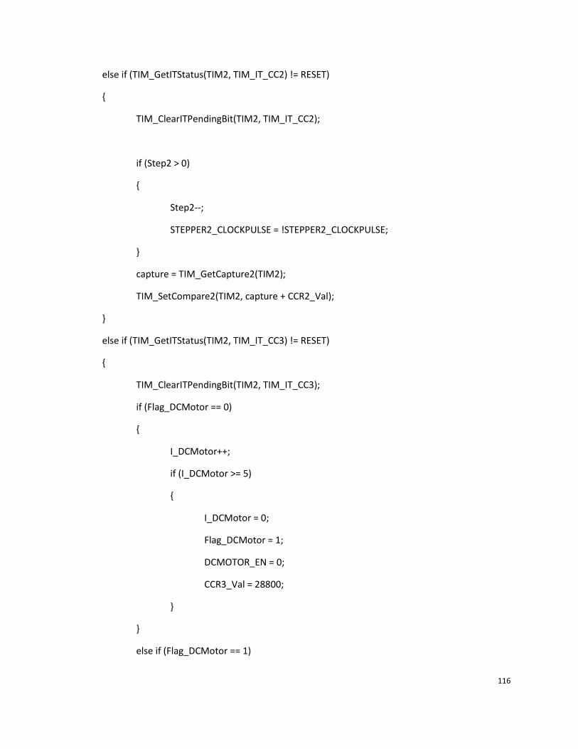
116
else if (TIM_GetITStatus(TIM2, TIM_IT_CC2) != RESET)
TIM_ClearITPendingBit(TIM2, TIM_IT_CC2);
if (Step2 > 0)
Step2--;
STEPPER2_CLOCKPULSE = !STEPPER2_CLOCKPULSE;
capture = TIM_GetCapture2(TIM2);
TIM_SetCompare2(TIM2, capture + CCR2_Val);
else if (TIM_GetITStatus(TIM2, TIM_IT_CC3) != RESET)
TIM_ClearITPendingBit(TIM2, TIM_IT_CC3);
if (Flag_DCMotor == 0)
I_DCMotor++;
if (I_DCMotor >= 5)
I_DCMotor = 0;
Flag_DCMotor = 1;
DCMOTOR_EN = 0;
CCR3_Val = 28800;
else if (Flag_DCMotor == 1)

117
I_DCMotor++;
if (I_DCMotor >= 5)
I_DCMotor = 0;
Flag_DCMotor = 0;
DCMOTOR_EN = 1;
CCR3_Val = (int)(28800 * DCMotor_DutyCycle);
capture = TIM_GetCapture3(TIM2);
TIM_SetCompare3(TIM2, capture + CCR3_Val);
else
TIM_ClearITPendingBit(TIM2, TIM_IT_CC4);
/* Pin PC.09 toggling with frequency = 439.4 Hz */
// GPIO_WriteBit(GPIOC, GPIO_Pin_7, (BitAction)(1 - GPIO_ReadOutputDataBit(GPIOC, GPIO_Pin_7)));
// capture = TIM_GetCapture4(TIM2);
// TIM_SetCompare4(TIM2, capture + CCR4_Val);
/**
* @brief This function handles ADC1 and ADC2 global interrupts requests.
* @param None
* @retval None
*/

118
void ADC1_2_IRQHandler(void)
if (ADC_GetFlagStatus(ADC1, ADC_FLAG_EOC)!=RESET)
ADC_ClearFlag(ADC1, ADC_FLAG_EOC);
if (ADC_GetFlagStatus(ADC1, ADC_FLAG_AWD)!=RESET)
LED_Infrared();
DCMotorCtrl(DCMOTOR_STOP, 0.0);
CylinderCtrl(1,CYLINDER_FORWARD,1000);
CylinderCtrl(1,CYLINDER_BACKWARD,1000);
DCMotorCtrl(DCMOTOR_START, 0.1);
ADC_ClearITPendingBit(ADC1, ADC_IT_AWD);
Appendix A.4 – main.c //X-Y plotter main program
/* Includes ------------------------------------------------------------------*/
#include "stm32f10x.h"
#include "sys.h"
#include "delay.h"
#include "led.h"
#include "math.h"
#include "stdlib.h"
/* Private typedef -----------------------------------------------------------*/
/* Private define ------------------------------------------------------------*/

119
#define BufferSize (0x0E)
/* Private macro -------------------------------------------------------------*/
/* Private variables ---------------------------------------------------------*/
//Timer variables
TIM_TimeBaseInitTypeDef TIM_TimeBaseStructure;
TIM_OCInitTypeDef TIM_OCInitStructure;
__IO uint16_t CCR1_Val = 720; //0.1ms
__IO uint16_t CCR2_Val = 720; //0.1ms
__IO uint16_t CCR3_Val = 16384;
__IO uint16_t CCR4_Val = 8192;
ErrorStatus HSEStartUpStatus;
//Stepper variabls
__IO uint32_t Step1; //Stepper 1 control signal (number of steps)
__IO uint32_t Step2; //Stepper 2 control signal (number of steps)
__IO uint32_t T_Stepper1;
__IO uint32_t T_Stepper2;
//start point and end point pointers
uint8_t *sxPrt;
uint8_t *syPrt;
uint8_t *exPrt;
uint8_t *eyPrt;
//Letter arrays
uint8_t Hx[]=0,10,':',10,10,';',10,10,':',10,30,30,30,'.';
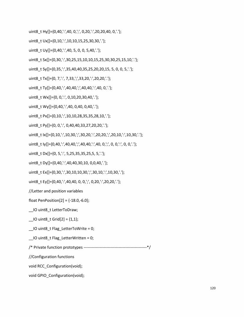
120
uint8_t Hy[]=0,40,':',40, 0,';', 0,20,':',20,20,40, 0,'.';
uint8_t Ux[]=0,10,':',10,10,15,25,30,30,'.';
uint8_t Uy[]=0,40,':',40, 5, 0, 0, 5,40,'.';
uint8_t Sx[]=0,30,':',30,25,15,10,10,15,25,30,30,25,15,10,'.';
uint8_t Sy[]=0,35,':',35,40,40,35,25,20,20,15, 5, 0, 0, 5,'.';
uint8_t Tx[]=0, 7,':', 7,33,';',33,20,':',20,20,'.';
uint8_t Ty[]=0,40,':',40,40,';',40,40,':',40, 0,'.';
uint8_t Wx[]=0, 0,':', 0,10,20,30,40,'.';
uint8_t Wy[]=0,40,':',40, 0,40, 0,40,'.';
uint8_t Px[]=0,10,':',10,10,28,35,35,28,10,'.';
uint8_t Py[]=0, 0,':', 0,40,40,33,27,20,20,'.';
uint8_t Ix[]=0,10,':',10,30,';',30,20,':',20,20,';',20,10,':',10,30,'.';
uint8_t Iy[]=0,40,':',40,40,';',40,40,':',40, 0,';', 0, 0,':', 0, 0,'.';
uint8_t Dx[]=0, 5,':', 5,25,35,35,25,5, 5,'.';
uint8_t Dy[]=0,40,':',40,40,30,10, 0,0,40,'.';
uint8_t Ex[]=0,30,':',30,10,10,30,';',30,10,':',10,30,'.';
uint8_t Ey[]=0,40,':',40,40, 0, 0,';', 0,20,':',20,20,'.';
//Letter and position variables
float PenPosition[2] = -18.0,-6.0;
__IO uint8_t LetterToDraw;
__IO uint8_t Grid[2] = 1,1;
__IO uint8_t Flag_LetterToWrite = 0;
__IO uint8_t Flag_LetterWritten = 0;
/* Private function prototypes -----------------------------------------------*/
//Configuration functions
void RCC_Configuration(void);
void GPIO_Configuration(void);

121
void TIM2_Configuration(void);
void NVIC_Configuration(void);
void USART_Configuration(void);
void ADC_Configuration(void);
//Linear motion functions
void MoveTray(u8 Direction, u8 StoreLocation[2]);
void StepperCtrl(u8 StepperNum, u8 Direction, float distance);
void CylinderCtrl(u8 CylinderNum, u8 Direction, int n_Delayms);
//XYPlotter functions
//void PenPositionInit(void);
void Char_Selection(uint8_t letter);
void MoveToNextGrid(void);
void XYPlotterDrawLine(uint8_t *sxPoint, uint8_t *syPoint, uint8_t *exPoint, uint8_t *eyPoint);
/* Private functions ---------------------------------------------------------*/
/**
* @brief Main program
* @param None
* @retval None
*/
int main(void)
/* System Clocks Configuration */
RCC_Configuration();
/* NVIC Configuration */
NVIC_Configuration();

122
/* GPIO Configuration */
GPIO_Configuration();
/* TIM1 Configuration */
TIM2_Configuration();
/* USART Configuration */
USART_Configuration();
delay_init(72); //hardware delay initailiztion
LED_Init();
delay_s(1);
// PenPositionInit();
/* Appication -- XY-Plotter*/
while (1)
Flag_LetterToWrite = 0;
USART_ITConfig(USART2, USART_IT_RXNE,ENABLE);
while (Flag_LetterToWrite == 0);
MoveToNextGrid();
// CylinderCtrl(2,CYLINDER_FORWARD,1000);
// CylinderCtrl(2,CYLINDER_BACKWARD,1000);
Char_Selection(LetterToDraw);
XYPlotterDrawLine(sxPrt, syPrt, exPrt, eyPrt);

123
//Test Code
// StepperCtrl(1, X_POSITIVE, 20.0);
// StepperCtrl(2, Y_POSITIVE, 20.0);
// while (Step1 > 0);
// while (Step2 > 0);
// CylinderCtrl(2,CYLINDER_FORWARD,1000);
// CylinderCtrl(2,CYLINDER_BACKWARD, 1000);
// while (1);
/**
* @brief Configures the different system clocks.
* @param None
* @retval None
*/
void RCC_Configuration(void)
/* Setup the microcontroller system. Initialize the Embedded Flash Interface,
initialize the PLL and update the SystemFrequency variable. */
SystemInit();
/* TIM1 clock enable */
RCC_APB1PeriphClockCmd(RCC_APB1Periph_TIM2, ENABLE);
/* GPIOA, GPIOB, GPIOE and AFIO clocks enable */

124
RCC_APB2PeriphClockCmd(RCC_APB2Periph_GPIOA | RCC_APB2Periph_GPIOC | RCC_APB2Periph_GPIOD | RCC_APB2Periph_AFIO | RCC_APB2Periph_GPIOE, ENABLE);
//Enable USART1 Clock
RCC_APB2PeriphClockCmd(RCC_APB2Periph_USART1, ENABLE);
//Enable USART2 Clock
RCC_APB1PeriphClockCmd(RCC_APB1Periph_USART2, ENABLE);
//Enable ADC1 Clock
RCC_APB2PeriphClockCmd(RCC_APB2Periph_ADC1, ENABLE);
/**
* @brief Configure the TIM1 Pins.
* @param None
* @retval None
*/
void GPIO_Configuration(void)
GPIO_InitTypeDef GPIO_InitStructure;
GPIO_InitTypeDef GPIO_IS;//GPIO initial structure
//Pneumatic component and DC motor GPIO initialization
GPIO_InitStructure.GPIO_Pin = GPIO_Pin_0 | GPIO_Pin_1 | GPIO_Pin_2 | GPIO_Pin_3 | GPIO_Pin_4 | GPIO_Pin_5 | GPIO_Pin_6 | GPIO_Pin_7 | GPIO_Pin_8| GPIO_Pin_9;
GPIO_InitStructure.GPIO_Pin |= GPIO_Pin_10 | GPIO_Pin_11 | GPIO_Pin_12;
GPIO_InitStructure.GPIO_Mode = GPIO_Mode_Out_PP;
GPIO_InitStructure.GPIO_Speed = GPIO_Speed_50MHz;

125
GPIO_Init(GPIOE, &GPIO_InitStructure);
//Stepper GPIO initialization
GPIO_InitStructure.GPIO_Pin = GPIO_Pin_5 | GPIO_Pin_6 | GPIO_Pin_9 | GPIO_Pin_10;
GPIO_InitStructure.GPIO_Mode = GPIO_Mode_Out_PP;
GPIO_InitStructure.GPIO_Speed = GPIO_Speed_50MHz;
GPIO_Init(GPIOC, &GPIO_InitStructure);
//USART Tx, Rx GPIO initialization
//Enable the USART2 Pins Software Remapping
GPIO_PinRemapConfig(GPIO_Remap_USART2, ENABLE);
//Configure USART1 Rx as input floating
GPIO_IS.GPIO_Pin = GPIO_Pin_10;
GPIO_IS.GPIO_Mode = GPIO_Mode_IN_FLOATING;
GPIO_Init(GPIOA, &GPIO_IS);
//Configure USART2 Rx as input floating
GPIO_IS.GPIO_Pin = GPIO_Pin_6;
GPIO_Init(GPIOD, &GPIO_IS);
//Configure USART1 Tx as alternate function push-pull
GPIO_IS.GPIO_Pin = GPIO_Pin_9;
GPIO_IS.GPIO_Speed = GPIO_Speed_50MHz;
GPIO_IS.GPIO_Mode = GPIO_Mode_AF_PP;

126
GPIO_Init(GPIOA, &GPIO_IS);
//Configure USART2 Tx as alternate function push-pull
GPIO_IS.GPIO_Pin = GPIO_Pin_5;
GPIO_Init(GPIOD, &GPIO_IS);
//Timer 2 configuration
void TIM2_Configuration(void)
TIM_TimeBaseInitTypeDef TIM_TimeBaseStructure;
TIM_OCInitTypeDef TIM_OCInitStructure;
/* Time base configuration */
TIM_TimeBaseStructure.TIM_Period = 65535;
TIM_TimeBaseStructure.TIM_Prescaler = 0;
TIM_TimeBaseStructure.TIM_ClockDivision = 0;
TIM_TimeBaseStructure.TIM_CounterMode = TIM_CounterMode_Up;
TIM_TimeBaseInit(TIM2, &TIM_TimeBaseStructure);
/* Prescaler configuration */
TIM_PrescalerConfig(TIM2, 4, TIM_PSCReloadMode_Immediate);
/* Output Compare Timing Mode configuration: Channel1 */
TIM_OCInitStructure.TIM_OCMode = TIM_OCMode_Timing;
TIM_OCInitStructure.TIM_OutputState = TIM_OutputState_Enable;
TIM_OCInitStructure.TIM_Pulse = CCR1_Val;

127
TIM_OCInitStructure.TIM_OCPolarity = TIM_OCPolarity_High;
TIM_OC1Init(TIM2, &TIM_OCInitStructure);
TIM_OC1PreloadConfig(TIM2, TIM_OCPreload_Disable);
/* Output Compare Timing Mode configuration: Channel2 */
TIM_OCInitStructure.TIM_OutputState = TIM_OutputState_Enable;
TIM_OCInitStructure.TIM_Pulse = CCR2_Val;
TIM_OC2Init(TIM2, &TIM_OCInitStructure);
TIM_OC2PreloadConfig(TIM2, TIM_OCPreload_Disable);
/* Output Compare Timing Mode configuration: Channel3 */
TIM_OCInitStructure.TIM_OutputState = TIM_OutputState_Enable;
TIM_OCInitStructure.TIM_Pulse = CCR3_Val;
TIM_OC3Init(TIM2, &TIM_OCInitStructure);
TIM_OC3PreloadConfig(TIM2, TIM_OCPreload_Disable);
/* Output Compare Timing Mode configuration: Channel4 */
TIM_OCInitStructure.TIM_OutputState = TIM_OutputState_Enable;
TIM_OCInitStructure.TIM_Pulse = CCR4_Val;
TIM_OC4Init(TIM2, &TIM_OCInitStructure);

128
TIM_OC4PreloadConfig(TIM2, TIM_OCPreload_Disable);
/* TIM IT enable */
TIM_ITConfig(TIM2, TIM_IT_CC1 | TIM_IT_CC2 | TIM_IT_CC3 | TIM_IT_CC4, ENABLE);
/* TIM2 enable counter */
TIM_Cmd(TIM2, ENABLE);
//Nested vectored interrupt controller configuration
void NVIC_Configuration(void)
NVIC_InitTypeDef NVIC_InitStructure;
NVIC_InitTypeDef NVIC_IS;//NVIC initial structure
//Configure the NVIC Preemption Priority Bits
NVIC_PriorityGroupConfig(NVIC_PriorityGroup_0);
/* Enable the TIM2 gloabal Interrupt */
NVIC_InitStructure.NVIC_IRQChannel = TIM2_IRQn;
NVIC_InitStructure.NVIC_IRQChannelSubPriority = 1;
NVIC_InitStructure.NVIC_IRQChannelCmd = ENABLE;
NVIC_Init(&NVIC_InitStructure);
//Enable the ADC Interrupt

129
NVIC_IS.NVIC_IRQChannel = ADC1_2_IRQn;
NVIC_IS.NVIC_IRQChannelSubPriority = 4;
NVIC_IS.NVIC_IRQChannelCmd = ENABLE;
NVIC_Init(&NVIC_IS);
//Enable the USART1 Interrupt
NVIC_IS.NVIC_IRQChannel = USART1_IRQn;
NVIC_IS.NVIC_IRQChannelSubPriority = 3;
NVIC_IS.NVIC_IRQChannelCmd = ENABLE;
NVIC_Init(&NVIC_IS);
// Enable the USART2 Interrupt
NVIC_IS.NVIC_IRQChannel = USART2_IRQn;
NVIC_IS.NVIC_IRQChannelSubPriority = 2;
NVIC_IS.NVIC_IRQChannelCmd = ENABLE;
NVIC_Init(&NVIC_IS);
//Configure USART1 and USART2
void USART_Configuration(void)
/* USART1 and USART2 configuration ------------------------------------------------------*/
/* USART1 and USART2 configured as follow:
- BaudRate = 9600 baud
- Word Length = 8 Bits
- One Stop Bit
- No parity

130
- Hardware flow control disabled (RTS and CTS signals)
- Receive and transmit enabled
*/
USART_InitTypeDef USART_IS;//USART initial structure
USART_IS.USART_BaudRate = 9600;
USART_IS.USART_WordLength = USART_WordLength_8b;
USART_IS.USART_StopBits = USART_StopBits_1;
USART_IS.USART_Parity = USART_Parity_No;
USART_IS.USART_HardwareFlowControl = USART_HardwareFlowControl_None;
USART_IS.USART_Mode = USART_Mode_Rx | USART_Mode_Tx;
/* Configure USART1 */
USART_Init(USART1, &USART_IS);
/* Configure USART2 */
USART_Init(USART2, &USART_IS);
// Enable USART1 Receive and Transmit interrupts */
USART_ITConfig(USART1, USART_IT_RXNE, DISABLE);
USART_ITConfig(USART1, USART_IT_TXE, DISABLE);
// Enable USART2 Receive and Transmit interrupts */
USART_ITConfig(USART2, USART_IT_RXNE, DISABLE);
USART_ITConfig(USART2, USART_IT_TXE, ENABLE);
// Enable the USART1 */
USART_Cmd(USART1, ENABLE);
// Enable the USART2 */

131
USART_Cmd(USART2, ENABLE);
//Configures ADC
void ADC_Configuration(void)
ADC_InitTypeDef ADC_IS; //ADC initial structure
GPIO_InitTypeDef ADC_I; //ADC Input Pin initial structure
//Configures Analog input pin
ADC_I.GPIO_Pin = GPIO_Pin_7;
ADC_I.GPIO_Mode = GPIO_Mode_AIN;
ADC_I.GPIO_Speed = GPIO_Speed_2MHz;
GPIO_Init(GPIOA, &ADC_I);
//Configures ADC
ADC_IS.ADC_Mode = ADC_Mode_Independent;//Use independent mode
ADC_IS.ADC_ScanConvMode = DISABLE;//Disable scan conversion mode
ADC_IS.ADC_ContinuousConvMode = ENABLE;//Enable continuous conversion mode
ADC_IS.ADC_ExternalTrigConv = ADC_ExternalTrigConv_None;//Disable external trigger conversion mode
ADC_IS.ADC_DataAlign = ADC_DataAlign_Right;
ADC_IS.ADC_NbrOfChannel = 1;
ADC_Init(ADC1, &ADC_IS);
ADC_RegularChannelConfig(ADC1, ADC_Channel_7, 1, ADC_SampleTime_239Cycles5);
ADC_AnalogWatchdogThresholdsConfig(ADC1, 0x0B00, 0x0300);
ADC_AnalogWatchdogSingleChannelConfig(ADC1, ADC_Channel_7);

132
ADC_AnalogWatchdogCmd(ADC1, ADC_AnalogWatchdog_SingleRegEnable);
ADC_ITConfig(ADC1, ADC_IT_AWD, ENABLE);
ADC_ITConfig(ADC1, ADC_IT_EOC, ENABLE);
ADC_Cmd(ADC1, ENABLE);
ADC_ResetCalibration(ADC1);
while(ADC_GetResetCalibrationStatus(ADC1));
ADC_SoftwareStartConvCmd(ADC1, ENABLE);
/* Stepper Control function*/
void StepperCtrl(u8 StepperNum, u8 Direction, float distance)
int Step;
Step = (int)(distance / 0.35 * 2.0);
if (StepperNum == 1)
STEPPER1_DIRECTION = Direction;
Step1 = Step;
// while (Step1 > 0);
else if (StepperNum == 2)

133
STEPPER2_DIRECTION = Direction;
Step2 = Step;
// while (Step2 > 0);
///* Pen position initialization */
//void PenPositionInit(void)
//
// StepperCtrl(1,X_POSITIVE,XDISTANCE_INIT);
// StepperCtrl(2,Y_POSITIVE,YDISTANCE_INIT);
// while ( (Step1 > 0) || (Step2 > 0) );
//
/* Move pen to the next location */
void MoveToNextGrid(void)
float distance;
float deltaX;
float deltaY;
uint8_t xDirection;
uint8_t yDirection;
deltaX = GRID_XLENGTH * (Grid[0] - 1) - PenPosition[0];
deltaY = GRID_YLENGTH * (Grid[1] - 1) - PenPosition[1];
if (deltaX > 0)

134
xDirection = X_POSITIVE;
else
xDirection = X_NEGATIVE;
if (deltaY > 0)
yDirection = Y_POSITIVE;
else
yDirection = Y_NEGATIVE;
deltaX = fabs(deltaX);
deltaY = fabs(deltaY);
distance = sqrt(deltaX*deltaX + deltaY*deltaY);
T_Stepper1 = (int)(T_STEPPERPULSE * distance / deltaX);
T_Stepper2 = (int)(T_STEPPERPULSE * distance / deltaY);
StepperCtrl(1,xDirection,deltaX);
StepperCtrl(2,yDirection,deltaY);
while ( (Step1 > 0) || (Step2 > 0) );
void Char_Selection(uint8_t letter)

135
switch (letter)
case 'D':
sxPrt = &Dx[0];
syPrt = &Dy[0];
exPrt = &Dx[1];
eyPrt = &Dy[1];
break;
case 'E':
sxPrt = &Ex[0];
syPrt = &Ey[0];
exPrt = &Ex[1];
eyPrt = &Ey[1];
break;
case 'H':
sxPrt = &Hx[0];
syPrt = &Hy[0];
exPrt = &Hx[1];
eyPrt = &Hy[1];
break;
case 'I':
sxPrt = &Ix[0];
syPrt = &Iy[0];
exPrt = &Ix[1];
eyPrt = &Iy[1];
break;
case 'P':
136
sxPrt = &Px[0];
syPrt = &Py[0];
exPrt = &Px[1];
eyPrt = &Py[1];
break;
case 'S':
sxPrt = &Sx[0];
syPrt = &Sy[0];
exPrt = &Sx[1];
eyPrt = &Sy[1];
break;
case 'T':
sxPrt = &Tx[0];
syPrt = &Ty[0];
exPrt = &Tx[1];
eyPrt = &Ty[1];
break;
case 'W':
sxPrt = &Wx[0];
syPrt = &Wy[0];
exPrt = &Wx[1];
eyPrt = &Wy[1];
break;
case 'U':
sxPrt = &Ux[0];
syPrt = &Uy[0];
exPrt = &Ux[1];

137
eyPrt = &Uy[1];
break;
default:
break;
void XYPlotterDrawLine(uint8_t *sxPoint, uint8_t *syPoint, uint8_t *exPoint, uint8_t *eyPoint)
float distance;
float deltaX;
float deltaY;
uint8_t xDirection;
uint8_t yDirection;
Flag_LetterWritten = 0;
while (Flag_LetterWritten == 0)
if (*exPoint > *sxPoint)
xDirection = X_POSITIVE;
else
xDirection = X_NEGATIVE;
if (*eyPoint > *syPoint)

138
yDirection = Y_POSITIVE;
else
yDirection = Y_NEGATIVE;
deltaX = fabs(*exPoint - *sxPoint);
deltaY = fabs(*eyPoint - *syPoint);
deltaX = (float)deltaX;
deltaY = (float)deltaY;
distance = sqrt(deltaX*deltaX + deltaY*deltaY);
T_Stepper1 = (int)(T_STEPPERPULSE * distance / deltaX);
T_Stepper2 = (int)(T_STEPPERPULSE * distance / deltaY);
StepperCtrl(1,xDirection,deltaX);
StepperCtrl(2,yDirection,deltaY);
while ( (Step1 > 0) || (Step2 > 0) );
sxPoint++;
syPoint++;
exPoint++;
eyPoint++;
if (*exPoint > 40)
if (*exPoint == ':')

139
CylinderCtrl(2,CYLINDER_FORWARD,1000);
if (*exPoint == ';')
CylinderCtrl(2,CYLINDER_BACKWARD,1000);
if (*exPoint == '.')
CylinderCtrl(2,CYLINDER_BACKWARD,1000);
Flag_LetterWritten = 1;
PenPosition[0] = GRID_XLENGTH * (Grid[0] - 1) + *sxPoint;
PenPosition[1] = GRID_YLENGTH * (Grid[1] - 1) + *syPoint;
sxPoint+=2;
syPoint+=2;
exPoint+=2;
eyPoint+=2;
/* Pneumatic cylinder control function */
void CylinderCtrl(u8 CylinderNum, u8 Direction, int n_Delayms)
if (Direction == CYLINDER_FORWARD)

140
switch (CylinderNum)
case 1: CYLINDER1_FORWARD = 1;
delay_ms(200);
CYLINDER1_FORWARD = 0;
break;
case 2: CYLINDER2_FORWARD = 1;
delay_ms(200);
CYLINDER2_FORWARD = 0;
break;
case 3: CYLINDER3_FORWARD = 1;
delay_ms(200);
CYLINDER3_FORWARD = 0;
break;
case 4: CYLINDER4_FORWARD = 1;
delay_ms(200);
CYLINDER4_FORWARD = 0;
break;
else if (Direction == CYLINDER_BACKWARD)
switch (CylinderNum)
case 1: CYLINDER1_BACKWARD = 1;
delay_ms(200);
CYLINDER1_BACKWARD = 0;

141
break;
case 2: CYLINDER2_BACKWARD = 1;
delay_ms(200);
CYLINDER2_BACKWARD = 0;
break;
case 3: CYLINDER3_BACKWARD = 1;
delay_ms(200);
CYLINDER3_BACKWARD = 0;
break;
case 4: CYLINDER4_BACKWARD = 1;
delay_ms(200);
CYLINDER4_BACKWARD = 0;
break;
delay_ms(n_Delayms);
#ifdef USE_FULL_ASSERT
/**
* @brief Reports the name of the source file and the source line number
* where the assert_param error has occurred.
* @param file: pointer to the source file name
* @param line: assert_param error line source number
* @retval None
*/

142
void assert_failed(uint8_t* file, uint32_t line)
/* User can add his own implementation to report the file name and line number,
ex: printf("Wrong parameters value: file %s on line %d\r\n", file, line) */
while (1)
#endif
/******************* (C) COPYRIGHT 2009 STMicroelectronics *****END OF FILE****/
Appendix A.5 – stm32f10x_it.c //X-Y plotter interrupts program
/* Includes ------------------------------------------------------------------*/
#include "stm32f10x_it.h"
#include "ctype.h"
#include "sys.h"
#include "led.h"
/** @addtogroup STM32F10x_StdPeriph_Examples
* @
*/
/** @addtogroup TIM_TimeBase
* @
*/
/* Private typedef -----------------------------------------------------------*/
/* Private define ------------------------------------------------------------*/

143
/* Private macro -------------------------------------------------------------*/
/* Private variables ---------------------------------------------------------*/
uint16_t capture = 0;
extern __IO uint16_t CCR1_Val;
extern __IO uint16_t CCR2_Val;
extern __IO uint16_t CCR3_Val;
extern __IO uint16_t CCR4_Val;
extern __IO uint8_t LetterToDraw;
extern __IO uint8_t Flag_LetterToWrite;
extern __IO uint8_t Grid[2];
uint8_t RxBuffer2[3];
uint8_t RxCounter2 = 0;
uint8_t TxCounter2 = 0;
extern __IO uint32_t Step1; //Stepper 1 control signal (number of steps)
extern __IO uint32_t Step2; //Stepper 2 control signal (number of steps)
extern __IO uint32_t T_Stepper1;
extern __IO uint32_t T_Stepper2;
__IO uint32_t I_Stepper1 = 0;
__IO uint32_t I_Stepper2 = 0;
/* Private function prototypes -----------------------------------------------*/
/* Private functions ---------------------------------------------------------*/
/******************************************************************************/

144
/* Cortex-M3 Processor Exceptions Handlers */
/******************************************************************************/
/**
* @brief This function handles Hard Fault exception.
* @param None
* @retval None
*/
void HardFault_Handler(void)
/* Go to infinite loop when Hard Fault exception occurs */
while (1)
/**
* @brief This function handles Memory Manage exception.
* @param None
* @retval None
*/
void MemManage_Handler(void)
/* Go to infinite loop when Memory Manage exception occurs */
while (1)

145
/**
* @brief This function handles Bus Fault exception.
* @param None
* @retval None
*/
void BusFault_Handler(void)
/* Go to infinite loop when Bus Fault exception occurs */
while (1)
/**
* @brief This function handles Usage Fault exception.
* @param None
* @retval None
*/
void UsageFault_Handler(void)
/* Go to infinite loop when Usage Fault exception occurs */
while (1)
/******************************************************************************/
/* STM32F10x Peripherals Interrupt Handlers */

146
/******************************************************************************/
/**
* @brief This function handles USARTz global interrupt request.
* @param None
* @retval None
*/
void USART2_IRQHandler(void)
if (USART_GetITStatus(USART2, USART_IT_RXNE) != RESET)
RxBuffer2[RxCounter2] = USART_ReceiveData(USART2);
//read the letter and position
RxCounter2++;
if (RxCounter2 == NBOFDATATOREAD2)
LED_Receive();
RxCounter2 = 0;
Flag_LetterToWrite = 1; //LetterToWrite flag
LetterToDraw = RxBuffer2[0];
Grid[0] = RxBuffer2[1] - 48;//Convert ASCII to DECIMAL
Grid[1] = RxBuffer2[2] - 48;
USART_ITConfig(USART2, USART_IT_RXNE, DISABLE);

147
if (USART_GetITStatus(USART2, USART_IT_TXE)!=RESET)
USART_ITConfig(USART2, USART_IT_TXE, DISABLE);
/**
* @brief This function handles TIM2 global interrupt request.
* @param None
* @retval None
*/
void TIM2_IRQHandler(void)
if (TIM_GetITStatus(TIM2, TIM_IT_CC1) != RESET)
TIM_ClearITPendingBit(TIM2, TIM_IT_CC1);
I_Stepper1++;
if (I_Stepper1 >= T_Stepper1)
I_Stepper1 = 0;
if (Step1 > 0)
Step1--;
STEPPER1_CLOCKPULSE = !STEPPER1_CLOCKPULSE;

148
capture = TIM_GetCapture1(TIM2);
TIM_SetCompare1(TIM2, capture + CCR1_Val);
else if (TIM_GetITStatus(TIM2, TIM_IT_CC2) != RESET)
TIM_ClearITPendingBit(TIM2, TIM_IT_CC2);
I_Stepper2++;
if (I_Stepper2 >= T_Stepper2)
I_Stepper2 = 0;
if (Step2 > 0)
Step2--;
STEPPER2_CLOCKPULSE = !STEPPER2_CLOCKPULSE;
capture = TIM_GetCapture2(TIM2);
TIM_SetCompare2(TIM2, capture + CCR2_Val);
else if (TIM_GetITStatus(TIM2, TIM_IT_CC3) != RESET)
TIM_ClearITPendingBit(TIM2, TIM_IT_CC3);
/* Pin PC.08 toggling with frequency = 219.7 Hz */

149
// GPIO_WriteBit(GPIOC, GPIO_Pin_8, (BitAction)(1 - GPIO_ReadOutputDataBit(GPIOC, GPIO_Pin_8)));
// capture = TIM_GetCapture3(TIM2);
// TIM_SetCompare3(TIM2, capture + CCR3_Val);
else
TIM_ClearITPendingBit(TIM2, TIM_IT_CC4);
/* Pin PC.09 toggling with frequency = 439.4 Hz */
// GPIO_WriteBit(GPIOC, GPIO_Pin_7, (BitAction)(1 - GPIO_ReadOutputDataBit(GPIOC, GPIO_Pin_7)));
// capture = TIM_GetCapture4(TIM2);
// TIM_SetCompare4(TIM2, capture + CCR4_Val);

150
Appendix B – LabVIEW Code
Appendix B.1 – Automated warehouse GUI LabVIEW code
Figure 66 – LabVIEW code for the Automated warehouse GUI
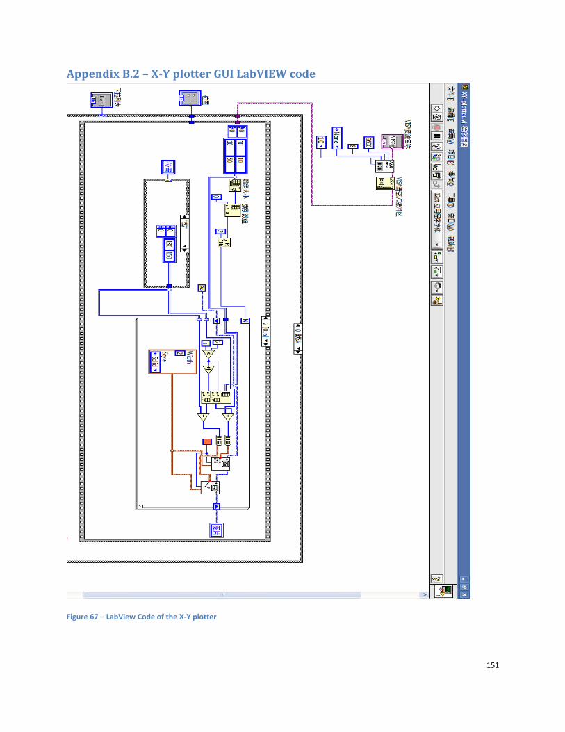
151
Appendix B.2 – X-Y plotter GUI LabVIEW code
Figure 67 – LabView Code of the X-Y plotter

152
References
Websites
Arduino, http://arduino.cc/en/Main/Hardware
ARM processor, http://www.arm.com/products/processors/index.php
Automated warehouse, http://www.freepatentsonline.com/5568393.pdf
AVR, http://www.atmel.com/products/avr/
Communications sensors, http://en.wikibooks.org/wiki/Robotics/Communication_Sensors
Logistic solutions, http://www.unitronics.com/Content.aspx?page=AutoWarehouse
LEGO, http://shop.lego.com/product/?p=8547&LangId=2057&ShipTo=US
ROBO TX, http://www.fischertechnik.biz/
MSP430, http://en.wikipedia.org/wiki/TI_MSP430
Motor controller, http://en.wikipedia.org/wiki/Motor_controller
Microcontroller, http://en.wikipedia.org/wiki/Microcontroller
Radio frequency, http://en.wikipedia.org/wiki/Radio_frequency
Sensors, http://en.wikipedia.org/wiki/Detector
Infrared proximity sensor, http://ikalogic.com/ir_prox_sensors.php,
http://www.solarbotics.net/library/circuits/sensors_prox.html#ir
VEX, http://www.vexrobotics.com/
Datasheets
2N3904, Transistor, http://www.fairchildsemi.com/ds/2N/2N3904.pdf
IRF520, Transistor, http://www.irf.com/product-info/datasheets/data/irf520.pdf
GP2D120XJ00F, Sensor, http://www.sparkfun.com/datasheets/Sensors/Infrared/GP2D120XJ00F_SS.pdf
L293D, Motor driver, http://www.datasheetcatalog.org/datasheet/texasinstruments/l293.pdf
L298, Motor driver,
http://pdf1.alldatasheet.com/datasheetpdf/view/22437/STMICROELECTRONICS/L298.html
SH2034D, Motor controller, http://www.chinasaideli.com/products/prod_info.asp?auto_id=1132
AT89C51, Microcontroller, http://www.atmel.com/dyn/resources/prod_documents/doc1919.pdf
STM32F107VC, Microcontroller, http://www.keil.com/dd/docs/datashts/st/stm32f10xxx.pdf
Reference Manual
STM32F107xx, http://www.keil.com/dd/docs/datashts/st/stm32f10xxx.pdf