development of a passive helium heat switch for fast cool
TRANSCRIPT
P#
013
1
Development of a Passive Helium Heat Switch
for Fast Cool Down by Two-Stage Cryocooler
I. Park, D. Yoo, J. Park, S. Jeong
Cryogenic Engineering Laboratory
Dept. of Mechanical Engineering
KAIST, Daejeon, Republic of Korea
ABSTRACT
A new type of thermal heat switch has been designed and analyzed using a numerical ap-
proach. A passive helium heat switch using adsorption of helium on activated charcoal is expected
to facilitate the rapid cool down of the second stage of a two-stage cryocooler. The heat switch
contains vertical fins in a staggered array, an activated charcoal bed, and helium gas. Those compo-
nents are isolated from the outside by a thin-walled cylinder. The heat switch thermally connects
the first and the second stage of a two-stage cryocooler at high temperature in order to utilize the
larger refrigeration capacity of the first stage for the initial second-stage cooling. When the second
stage reaches a certain low temperature, the heat switch opens and thermally isolates the second
stage from the first. The thermal connection between the first and second stages is determined by
the pressure of the helium gas in the switch, which is the function of activated charcoal bed tem-
perature.
In this paper, the cooling time of the second stage is calculated by a heat transfer analysis that
takes into account the helium gas adsorption on the activated charcoal, the various flow regimes in
a vacuum environment, and an energy balance. The calculated heat transfer rate between the fins
shows that the thermal resistance of the designed heat switch can be changed passively with the
variation of the temperature, and a thermal resistance ratio of more than 2000 can be achieved.
Moreover, the numerical results indicate that the cooling time for a 9 kg copper block using the
two-stage cryocooler (RDK-415D) with the heat switch will be reduced by 71 %.
INTRODUCTION
A gas-gap heat switch is a device which thermally connects (ON state) and disconnects (OFF
state) two objects for a specific purpose. As early as 1973, researchers began introducing the con-
cept of a gas-gap heat switch in order to improve the lifetime of cooling systems for the electronic
equipment in spacecraft. An article by R.P. Bywaters and R.A. Griffin1 describes the prototype of a
gas-gap heat switch. The experimental results of this prototype indicate that the thermal resistance
can be changed by more than a factor of 500 by varying the helium pressure in the switch gaps.
However, in order to change the ON to the OFF state, the prototype needs to be evacuated by a
vacuum pump. P.J. Shirron et al.2 introduced passive gas-gap heat switches for adiabatic demagne-
tization refrigerators. The heat switches passively turn off (OFF state) near 1 K or 4 K, relying on
the temperature dependence of the vapor pressure of 4He adsorbed onto neon or copper substrates,
respectively.
547
Cryocoolers 18, edited by S.D. Miller and R.G. Ross, Jr.©¶International Cryocooler Conference, Inc., Boulder, CO, 2014 577

P#
013
2A gas-gap heat switch also can be applied to a two-stage cryocooler. For example, supercon-
ducting magnets are typically cooled by two-stage cryocoolers. This kind of superconducting mag-
net without using liquid helium for its cooling has received significant attention in recent years.3-7
The conduction-cooled systems are easy to operate and do not require any liquid cryogens. How-
ever, it generally takes a very long time to cool down the superconducting magnet by the second
stage of a two-stage cryocooler. For instance, the cryogenic cooling system using a two-stage cryo-
cooler (RDK415D, Sumitomo) for a superconducting magnet developed by Y. S. Choi et al.7 re-
quires about 14 hours of cool down time for initial operation.
In order to achieve a fast cool-down rate by a two-stage cryocooler, many researchers8-10
have
developed cryogenic thermosiphones where the two-phase fluid plays a very efficient heat transfer
role based on its boiling and condensation phenomena inside the thermosiphon. The thermosiphon
has higher thermal conductance than pure copper during its ON-state and its conductance can be
turned off when its working fluid freezes due to the low temperature of the 2nd
stage of cryocooler.
A cryogenic thermosiphon charged with the proper fluid and installed between the first and the
second stages of a cryocooler can be regarded as a thermal diode and greatly reduces the cooldown
time of the object that is attached to the second stage.
On the other hand, instead of using a two-phase fluid heat switch such as a thermosiphon,
H. Chang and H. Kim11
developed a gas-gap heat switch. The heat switch employs nitrogen gas
and connects the first and the second stages of a two-stage cryocooler to take advantage of the large
cooling capacity at the first stage. The main merit of the heat switch is that the OFF state can be
achieved without any external actuation because the nitrogen gas is frozen, and the corresponding
vapor pressure inside of the heat switch is greatly decreased. On the other hand, if the gap of the
conductive surfaces is very small, the frost of nitrogen can stick to the surfaces and cause additional
heat conduction during the OFF state. Since the spacing of the conductive surfaces significantly
affects the thermal conduction of the gas, solidification of nitrogen gas makes it technically diffi-
cult to reduce the gap in order to improve thermal conduction of the heat switch.
Helium gas has been employed as the thermal conductor inside gas-gap heat switches by many
previous researchers1, 2, 12, 13
because of its high thermal conductance and adequacy of its operating
temperature. In order to utilize a helium heat switch for a two-stage cryocooler, we need an efficient
method to turn off the helium heat switch passively above 4 K. D. Martins13
developed a helium
heat switch which uses a sorption pump as the actuating device. The sorption pump consists of an
activated charcoal bed in order to adsorb and desorb the helium gas depending on the temperature
of the activated charcoal. In this case, the sorption pump needs to be cooled and heated by the
cryocooler and a heater, respectively. If the temperature of the activated charcoal bed changes with-
out any additional device, a helium heat switch can passively switch the ON and OFF stages.
This paper introduces a new type of passive helium heat switch for fast cool down of cryogenic
systems using a two-stage cryocooler. The heat switch is designed to change the ON to OFF state at
a temperature of around 50 K. The performance of the heat switch is analyzed by numerical calcu-
lation. Furthermore, the cooling time of a copper block using a two-stage cryocooler with the heat
switch is calculated and compared to that without the heat switch. The main parameters which
affect the performance of the heat switch are discussed in this paper.
DESIGN SCHEMES
Correlation of Isotherms
Figure 1 provides a schematic illustration of the heat switch. The heat switch is a closed con-
tainer and consists of upper copper fins, lower copper fins, activated charcoal bed, and thin-walled
stainless steel tube. The gap between upper and lower copper fins has been filled with helium gas.
When the heat switch is cooled, the gas pressure decreases by adsorption of helium gas on the
activated charcoal bed. The mass of the adsorbed helium gas can be determined by the correlation
of absorption isotherms.
L. Duband et al.15
have proposed the following correlation for adsorption isotherms of helium
on activated charcoal for the pressure range from 100 kPa to 3 MPa.
548 Cryocooler Integration Tech. & Application Lessons 580578 CRYOCOOLER INTEGRATION TECH. & APPLICATION LESSONS

P#
013
3
Figure 2. Adsorption isotherms for the helium gas14
and the correlation developed by L. Duband et al.15
Figure 1. The helium gas heat switch using a activated charcoal bed.
(1)
Here, C is the mass of helium gas adsorbed per unit mass of charcoal. This correlation is valid
for a temperature range from 15 K to 70 K. Since the helium gas pressure in the heat switch is lower
than 100 kPa, the correlation has to be compared with experimental results in the low pressure
range. D. Martins et al.14
have measured adsorption isotherms for helium gas and their results are
compared with the correlation in Fig. 2. We observe that this correlation is fairly consistent with
the experimental data in the low pressure range from 0.01 kPa to 100 kPa. If we know the mass
(mcharcoal
) of activated charcoal bed and the volume of helium gas (V), the gas pressure is then
determined using the following ideal gas equation.
(2)
where minit
is the initial mass of the helium gas; R is universal gas constant; and TLM
is the log mean
temperature between the upper and the lower copper fins. In this paper, however, the software
REFPROP (NIST) version 9.1 is employed to calculate gas pressure instead of using the ideal gas
equation for more precise results.
549PASSIVE HELIUM HEAT SWITCH FOR FAST COOL DOWN 581579PASSIVE HELIUM HEAT SWITCH FOR FAST COOL DOWN

P#
013
4
Figure 3. Schematic representation of a conduction cooled system by a two-stage cryocooler
Heat Transfer Coefficient
In order to determine the representative heat transfer coefficient between the upper and lower
fins, the flow regimes in the heat switch have to be estimated. The flow regime is a main factor to
determine the state (ON or OFF) of the heat switch and can be deduced in terms of the Knudsen
number as follows16
:
(3)
where Kn, ê, and Û are the Knudsen number, the gas mean free path, and the gas gap between the
lower and upper copper fins respectively. In the continuum flow regime, because the gas gap is very
small compared to length of the fins, the heat transfer coefficient between the fins can be calculated
by thermal conductivity of the gas (kg).
(4)
In the free-molecular flow regime, the gas molecules rarely strike each other.16
Therefore,
individual gas molecules directly transfer energy from one heat-switch surface to another. The
equation for the heat transfer between two parallel surfaces11, 17
is expressed as
(5)
where Ù, â, and M are accommodation coefficient, the ratio of specific heats, and the molecular
weight of the gas, respectively. The accommodation coefficient is taken as 0.5, which is valid for
helium gas [14]. As a result, Equations (1-5) show that the heat transfer coefficient between the
fins is a function of the temperature.
Cooling Time Calculation
The overall cooling time is calculated by considering an energy balance. A schematic diagram
of the cooling system using a two-stage cryocooler is illustrated in Fig.3. Each stage of the two-
stage cryocooler cools down the copper block with the mass of m1st
, m2nd
. The heat switch is
550 Cryocooler Integration Tech. & Application Lessons 582580 CRYOCOOLER INTEGRATION TECH. & APPLICATION LESSONS
P#
013
5
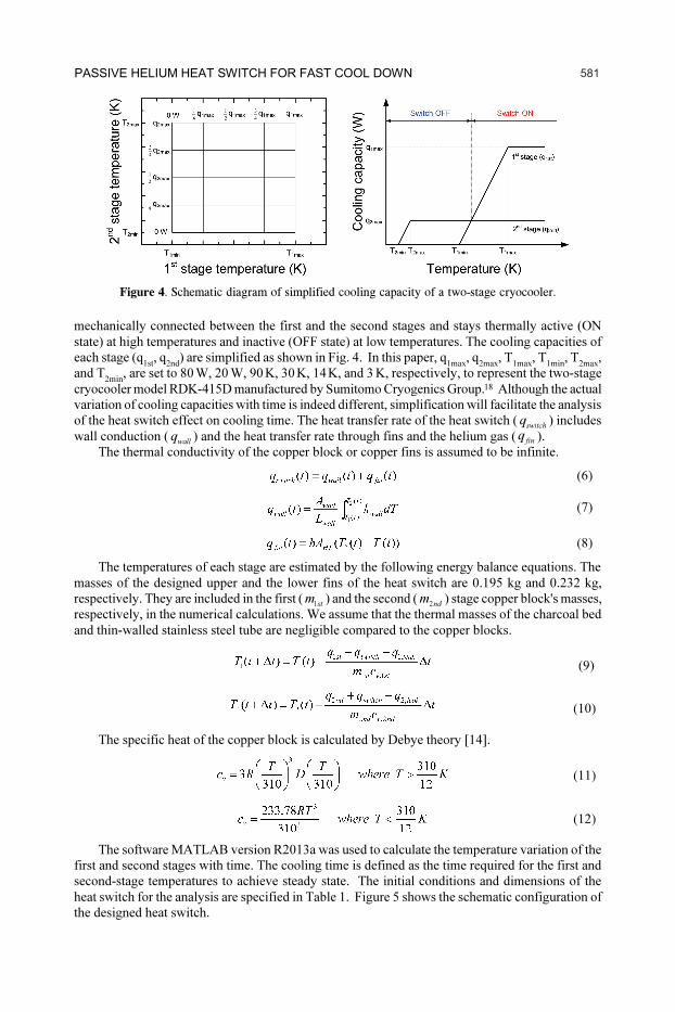
mechanically connected between the first and the second stages and stays thermally active (ON
state) at high temperatures and inactive (OFF state) at low temperatures. The cooling capacities of
each stage (q1st
, q2nd
) are simplified as shown in Fig. 4. In this paper, q1max
, q2max
, T1max
, T1min
, T2max
,
and T2min
, are set to 80¶W, 20¶W, 90¶K, 30¶K, 14¶K, and 3¶K, respectively, to represent the two-stage
cryocooler model RDK-415D manufactured by Sumitomo Cryogenics Group.18
Although the actual
variation of cooling capacities with time is indeed different, simplification will facilitate the analysis
of the heat switch effect on cooling time. The heat transfer rate of the heat switch (switch
q ) includes
wall conduction (wall
q ) and the heat transfer rate through fins and the helium gas (fin
q ).
The thermal conductivity of the copper block or copper fins is assumed to be infinite.
(6)
(7)
(8)
The temperatures of each stage are estimated by the following energy balance equations. The
masses of the designed upper and the lower fins of the heat switch are 0.195 kg and 0.232 kg,
respectively. They are included in the first (1st
m ) and the second (2nd
m ) stage copper block's masses,
respectively, in the numerical calculations. We assume that the thermal masses of the charcoal bed
and thin-walled stainless steel tube are negligible compared to the copper blocks.
(9)
(10)
The specific heat of the copper block is calculated by Debye theory [14].
(11)
(12)
The software MATLAB version R2013a was used to calculate the temperature variation of the
first and second stages with time. The cooling time is defined as the time required for the first and
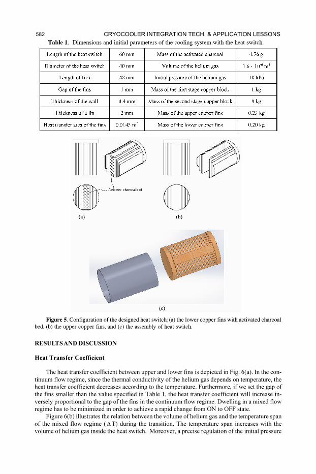
second-stage temperatures to achieve steady state. The initial conditions and dimensions of the
heat switch for the analysis are specified in Table 1. Figure 5 shows the schematic configuration of
the designed heat switch.
Figure 4. Schematic diagram of simplified cooling capacity of a two-stage cryocooler.
551PASSIVE HELIUM HEAT SWITCH FOR FAST COOL DOWN 583581PASSIVE HELIUM HEAT SWITCH FOR FAST COOL DOWN
P#
013
6Table 1. Dimensions and initial parameters of the cooling system with the heat switch.
Figure 5. Configuration of the designed heat switch: (a) the lower copper fins with activated charcoal
bed, (b) the upper copper fins, and (c) the assembly of heat switch.
RESULTS AND DISCUSSION
Heat Transfer Coefficient
The heat transfer coefficient between upper and lower fins is depicted in Fig. 6(a). In the con-
tinuum flow regime, since the thermal conductivity of the helium gas depends on temperature, the
heat transfer coefficient decreases according to the temperature. Furthermore, if we set the gap of
the fins smaller than the value specified in Table 1, the heat transfer coefficient will increase in-
versely proportional to the gap of the fins in the continuum flow regime. Dwelling in a mixed flow
regime has to be minimized in order to achieve a rapid change from ON to OFF state.
Figure 6(b) illustrates the relation between the volume of helium gas and the temperature span
of the mixed flow regime ( Δ T) during the transition. The temperature span increases with the
volume of helium gas inside the heat switch. Moreover, a precise regulation of the initial pressure
552 Cryocooler Integration Tech. & Application Lessons 584582 CRYOCOOLER INTEGRATION TECH. & APPLICATION LESSONS

P#
013
7
(b)(a)
Figure 6. Heat transfer coefficient as a function of temperature with the gap of 1 mm (a) and mixed
flow region with the volume of the heat switch (b).
(P@ 300 K) of the helium fill gas is needed when the heat switch has a large gas volume. If the volume
of helium gas increases, the pressure change of the helium gas due to adsorption of the activated
charcoal bed will decrease. Therefore, the initial pressure should be set slightly higher than the
pressure for the mixed flow regime. For these reasons, any unnecessary helium gas volume should
be removed when one develops a helium gas heat switch with an activated charcoal bed. The heat
transfer coefficient in the mixed flow regime is estimated by the two asymptotes between the con-
tinuum flow and the free-molecular flow regime. It should be noted that the heat transfer rate of
rarefied gas exponentially decreases when the temperature of the heat switch decreases lower than
38 K. The calculation of the heat transfer coefficient with temperature shows that the thermal resis-
tance of the helium heat switch can be modulated by more than a factor of 2000.
Cooling Time Calculation
Figure 7(a) shows a comparison of the cooling time with and without the heat switch. The
external heat leaks to the first and the second stage are neglected in the cooling time calculation.
The cooling system with the heat switch has a small temperature difference between the first and
the second stages. This is because the heat switch facilitates the first stage to cool down the cooling
load attached at the second stage and thus reduces the cooling time. When the heat switch reaches
the temperature where free-molecular flow initiates, the heat transfer coefficient rapidly decreases
and causes thermal isolation. As a result, the second stage becomes solely responsible for further
cooling of the copper block to achieve its target temperature. In the case of a cooling system without
the heat switch, the temperature of the second stage decreases slowly because the second stage
cannot take advantage of the higher cooling capacity of the first stage at all.
Figure 7. Calculated the cool down time with and without the heat switch (a), and the estimated heat
transfer coefficient during cool down (b).
(b)(a)
553PASSIVE HELIUM HEAT SWITCH FOR FAST COOL DOWN 585583PASSIVE HELIUM HEAT SWITCH FOR FAST COOL DOWN

P#
013
8
(a) (b)
(c)
Figure 8 shows how the cooling time and the heat transfer rate vary with the heat transfer area
of the fins. The results show that the cooling time decreases as the heat transfer area increases.
However, there is a limit to reduce the cooling time. If the heat transfer area is infinite at the ON
state, the maximum heat transfer rate of the heat switch can be calculated by the following equa-
tion:
(13)
Since the cooling capacities of the first and second stages (q1st
, q2nd
) are set to constant values
of 80 W and 20 W, respectively, we can deduce from Eq. (13) that the maximum heat transfer rate
is 70 W. For this reason, the heat transfer rates shown in Fig. 8 cannot exceed 70 W, although the
heat transfer area is further increased.
CONCLUSION
In this paper, we have presented a new design of a helium heat switch using adsorption charac-
teristic of activated charcoal. The designed heat switch can change its thermal resistance passively
with the variation of temperature. The numerical analysis predicts that the switch resistance ratio
can be on the order of 2000. The cooling time of a copper block is estimated using the simplified
cooling capacity map of a two-stage cryocooler. In spite of the simplification, the calculation
results clearly demonstrate the effectiveness of the heat switch on the cooling time. Although the
performance of the designed heat switch is not yet verified, our study provides a framework for the
development of an efficient helium gas heat switch.
Figure 8. The cooling time and heat transfer rate of the heat switch with a heat transfer area of
AHT
= 0.004 m2
(a), 0.0145 m2
(b), and 0.05 m2
(c), respectively.
554 Cryocooler Integration Tech. & Application Lessons 586584 CRYOCOOLER INTEGRATION TECH. & APPLICATION LESSONS

P#
013
9ACKNOWLEDGMENT
The research was supported by the Converging Research Center Program through the Ministry
of Science, ICT and Future Planning, Korea (2013K000406)
REFERENCES
1. Bywaters, R. P. and Griffin, R. A., “A gas-gap thermal switch for cryogenic applications,” Cryogenics,
vol. 13, no. (1973), pp. 344-349.
2. Shirron, P. J., Canavan, E. R., DiPirro, M. J., Jackson, M., Panek, J., and Tuttle, J. G. “Passive gas-gap
heat switches for use in adiabatic demagnetization refrigerators,” AIP Conference Proceedings, (2002),
pp. 1175-1182.
3. Watanabe, K., Awaji, S., Sakuraba, J., Watazawa, K., Hasebe, T., Jikihara, K., Yamada, Y., and Ishihara,
M., “11 T liquid helium-free superconducting magnet,” Cryogenics, vol. 36, no. 12 (1996), pp. 1019-
1025.
4. Kobayashi, T., Sato, Y., Sasaki, T., and Mine, S., “Manufacturing of Liquid Helium Free Supercon-
ducting Magnets for Industrial Use,” Advances in Cryogenic Engineering, Vol. 43. (1998), pp. 157-
163.
5. Hasebe, T., Sakuraba, J., Jikihara, K., Watazawa, K., Mitsubori, H., Sugizaki, Y., Okubo, H., Yamada,
Y., Awaji, S., and Watanabe, K., “Cryocooler Cooled Superconducting Magnets and Their Applica-
tions.” Advances in Cryogenic Engineering, Vol. 43. (1998), pp. 291-297.
6. Hase, T., Shibutani, K., Hayashi, S., Shimada, M., Ogawa, R., and Kawate, Y., “Generation of 1 T, 0.5
Hz alternating magnetic field in room temperature bore of cryocooler-cooled Bi-2212 superconducting
magnet,” Cryogenics, vol. 36, no. 12 (1996), pp. 971-977.
7. Choi, Y. S., Kim, D. L., and Shin, D. W., “Optimal cool-down time of a 4 K superconducting magnet
cooled by a two-stage cryocooler,” Cryogenics, vol. 52, no. 1 (2012), pp. 13-18.
8. Jeong, S., Kim, Y., Noh, C., Kim, S., and Jin, H., “Experimental investigation on the detachable thermo-
siphon for conduction-cooled superconducting magnets,” Cryogenics, vol. 46, no. 10 (2006), pp. 705-
710.
9. Prenger, F. C., Hill, D. D., Daney, D. E., Daugherty, M. A., Green, G. F., Chafe, J., Heiberger, M., and
Langhorn, A., “Performance of Cryocooler Shunt Heat Pipes,” Advances in Cryogenic Engineering,
Vol. 43, (1998), pp. 1521-1528.
10. Prenger, F. C., Hill, D. D., Daney, D. E., Daugherty, M. A., Green, G. F., and Roth, E. W., “Nitrogen
Heat Pipe for Cryocooler Thermal Shunt,” Advances in Cryogenic Engineering, Vol. 41. (1996), pp.
147-154.
11. Chang, H.-M. and Kim, H.-J., “Development of a thermal switch for faster cool-down by two-stage
cryocooler,” Cryogenics, vol. 40, no. 12 (2000), pp. 769-777.
12. Nast, T., Bell, G., and Barnes, C., “Development of gas gap cryogenic thermal switch,” Advances in
Cryogenic Engineering, Vol. 27, (1981), pp. 1117-1124.
13. Martins, D., Ribeiro, L., Lopes, D., Catarino, I., Esteves, I. A. A. C., Mota, J. P. B., and Bonfait, G.,
“Sorption characterization and actuation of a gas-gap heat switch,” Sensors and Actuators A: Physical,
vol. 171, no. 2 (2011), pp. 324-331.
14. Martins, D., Catarino, I., Lopes, D., Esteves, I. A. A. C., Mota, J. P. B., and Bonfait, G., “Low tempera-
ture adsorption versus pore size in activated carbons,” Cryocoolers 16, ICC Press, Boulder CO, pp.
567-573.
15. Duband, L., Ravex, A., and Chaussy, J., “Adsorption isotherms of helium on activated charcoal,”
Cryogenics, vol. 27, no. 7 (1987), pp. 397-400.
16. Barron, R. F., Cryogenic systems 2nd ed., Oxford (1985).
17. White, G. K., Experimental techniques in low-temperature physics. 3rd ed., Oxford (1979).
18. RDK-415D 4K Cryocooler Series, Available from: http://www.shicryogenics.com/products/4k-cryo-
coolers/rdk-415d-4k-cryocooler-series/.
555PASSIVE HELIUM HEAT SWITCH FOR FAST COOL DOWN 587585PASSIVE HELIUM HEAT SWITCH FOR FAST COOL DOWN