development of a model to predict flow oscillations in low
TRANSCRIPT

Development of a Model to PredictFlow Oscillations in Low-Flow Sodium Boiling
by
Alan E. LevinPeter Griffith
Energy Laboratory Report No. MIT-EL-80-006
April 1980

MITLibrariesDocument Services
Room 14-055177 Massachusetts AvenueCambridge, MA 02139Ph: 617.253.5668 Fax: 617.253.1690Email: [email protected]://Iibraries.mit.edu/docs
DISCLAIMER OF QUALITY
Due to the condition of the original material, there are unavoidableflaws in this reproduction. We have made every effort possible toprovide you with the best copy available. If you are dissatisfied withthis product and find it unusable, please contact Document Services assoon as possible.
Thank you.
Some pages in the original document contain pictures,graphics, or text that is illegible.
i77

REPORTS IN REACTOR THERMAL HYDARULICS RELATED TO THE
MIT ENERGY LABORATORY ELECTRIC POWER PROGRAM
A. Topical Reports (For availability check Energy LaboratoryHeadquarters, Room E19-439, MIT, Cambridge,Massachusetts, 02139)
A.1 General ApplicationsA.2 PWR ApplicationsA.3 BWR ApplicationsA.4 LMFBR Applications
A.1 M. Massoud, "A Condensed Review of Nuclear Reactor Thermal-Hydraulic Computer Codes for Two-Phase Flow Analysis," MITEnergy Laboratory Report MIT-EL-79-018, February 1979.
J.E. Kelly and M.S. Kazimi, "Development and Testing of theThree Dimensional, Two-Fluid Code THERMIT for LWR Core andSubchannel Applications," MIT Energy Laboratory ReportMIT-EL-79-046, December 1979.
A.2 P. Moreno, C. Chiu, R. Bowring, E. Khan, J. Liu, N. Todreas,"Methods for Steady-State Thermal/Hydraulic Analysis of PWRCores," MIT Energy Laboratory Report MIT-EL-76-006, Rev. 1,July 1977 (Orig. 3/77).
J.E. Kelly, J. Loomis, L. Wolf, "LWR Core Thermal-HydraulicAnalysis--Assessment and Comparison of the Range of Applica-bility of the Codes COBRA-IIIC/MIT and COBRA IV-l," MITEnergy Laboratory Report MIT-EL-78-026, September 1978.
J. Liu, N. Todreas, "Transient Thermal Analysis of PWR's bya Single Pass Procedure Using a Simplified Model Layout," MITEnergy Laboratory Report MIT-EL-77-008, Final, February 1979,(Draft, June 1977).
J. Liu, N. Todreas, "The Comparison of Available Data on PWRAssembly Thermal Behavior with Analytic Predictions," MITEnergy Laboratory Report MIT-EL-77-009, Final, February 1979,(Draft, June 1977).
A.3 L. Guillebaud, A. Levin, W. Boyd, A. Faya, L. Wolf, "WOSUB-A Subchannel Code for Steady-State and Transient Thermal-Hydraulic Analysis of Boiling Water Reactor Fuel Bundles,"Vol. II, Users Manual, MIT-EL-78-024. July 1977.

ii
L. Wolf, A Faya, A. Levin, W. Boyd, L. Guillebaud, "WOSUB-A Subchannel Code for Steady-State and Transient Thermal-Hydraulic Analysis of Boiling Water Reactor Fuel Pin Bundles,"Vol. III, Assessment and Comparison, MIT-EL-78-025, October 1977-.
L. Wolf, A. Faya, A. Levin, L. Guillebaud, "WOSUB-A SubchannelCode for Steady-State Reactor Fuel Pin Bundles," Vol. I, ModelDescription, MIT-EL-78-023, September 1978.
A. Faya, L. Wolf and N. Todreas, "Development of a Method forBWR Subchannel Analysis," MIT-EL-79-027, November 1979.
A. Faya, L. Wolf and N. Todreas, "CANAL User's Manual," MIT-EL-79-028, November 1979.
A.4 W.D. Hinkle, "Water Tests for Determining Post-Voiding Behaviorin the LMFBR," MIT Energy Laboratory Report MIT-EL-76-005,June 1976.
W.D. Hinkle, Ed., "LMFBR Safety and Sodium Boiling - A Stateof the Art Reprot," Draft DOE Report, June 1978.
M.R. Granziera, P. Griffith, W.D. Hinkle, M.S. Kazimi, A. Levin,M. Manahan, A. Schor, N. Todreas, G. Wilson, "Development ofComputer Code for Multi-dimensional Analysis of Sodium Voidingin the LMFBR," Preliminary Draft Report, July 1979.
M. Granziera, P. Griffith, W. Hinkle (ed.), M. Kazimi, A. Levin,M. Manahan, A. Schor, N. Todreas, R. Vilim, G. Wilson, "Develop-ment of Computer Code Models for Analysis of Subassembly Voidingin the LMFBR," Interim Report of the MIT Sodium Boiling ProjectCovering Work Through September 30, 1979, MIT-EL-80-005.
A. Levin and P. Griffith, "Development of a Model to PredictFlow Oscillations in Low-Flow Sodium Boiling," MIT-EL-80-006,April 1980.
M.R. Granziera and M. Kazimi, "A Two Dimensional, Two FluidModel for Sodium Boiling in LMFBR Assemblies," MIT-EL-80-011,May 1980.
G. Wilson and M. Kazimi, "Development of Models for the SodiumVersion of the Two-Phase Three Dimensional Thermal HydraulicsCode THERMIT," MIT-EL-80-010, May 1980.

iii
B. Papers
B.1 General ApplicationsB.2 PWR ApplicationsB.3 BWR ApplicationsB.4 LMFBR Applications
B.1 J.E. Kelly and M.S. Kazimi, "Development of the Two-Fluid
Multi-Dimensional Code THERMIT for LWR Analysis," accepted
for presentation 19th National Heat Transfer Conference,Orlando, Florida, August 1980.
J.E. Kelly and M.S. Kazimi, "THERMIT, A Three-Dimensional,Two-Fluid Code for LWR Transient Analysis," accepted for
presentation at Summer Annual American Nuclear SocietyMeeting, Las Vegas, Nevada, June 1980.
B.2 P. Moreno, J. Kiu, E. Khan, N. Todreas, "Steady State Thermal
Analysis of PWR's by a Single Pass Procddure Using a Simpli-fied Method," American Nuclear Society Transactions, Vol. 26
P. Moreno, J. Liu, E. Khan, N. Todreas, "Steady-State ThermalAnalysis of PWR's by a Single Pass Procedure Using a SimplifiedNodal Layout," Nuclear Engineering and Design, Vol. 47, 1978,pp. 35-48.
C. Chiu, P. Moreno, R. Bowring, N. Todreas, "Enthalpy TransferBetween PWR Fuel Assemblies in Analysis by the Lumped Sub-channel Model," Nuclear Engineering and Design, Vol. 53, 1979,165-186.
B.3 L. Wolf and A. Faya, "A BWR Subchannel Code with Drift Fluxand Vapor Diffusion Transport," American Nuclear SocietyTransactions, Vol. 28, 1978, p. 553.
B.4 W.D. Hinkle, (MIT), P.M Tschamper (GE), M.H. Fontana, (ORNL),R.E. Henry (ANL), and A. Padilla, (HEDL), for U.S. Departmentof Energy, "LMFBR Safety & Sodium Boiling," paper presented atthe ENS/ANS International Topical Meeting on Nuclear ReactorSafety, October 16-19, 1978, Brussels, Belgium.
M.I. Autruffe, G.J. Wilson, B. Stewart and M. Kazimi, "A Pro-posed Momentum Exchange Coefficient for Two-Phase Modeling ofSodium Boiling," Proc. Int. Meeting Fast Reactor Safety Tech-nology, Vol. 4, 2512-2521, Seattle, Washington, August 1979.
M.R. Granziera and M.S. Kazimi, "NATOF-2D: A Two DimensionalTwo-Fluid Model for Sodium Flow Transient Analysis," Trans. ANS,33, 515, November 1979.

NOTICE
This report was prepared as an account of worksponsored by the United States Government andtwo of its subcontractors. Neither the UnitedStates nor the United States Department of Energy,nor any of their employees, nor any of their con-tractors, subcontractors, or their employees,makes any warranty, express or implied, or assumesany legal liability or responsibility for theaccuracy, completeness or usefulness of anyinformation, apparatus, product or process dis-closed, or represents that its use would notinfringe privately owned rights.

DEVELOPMENT OF A MODEL TO PREDICT
FLOW OSCILLATIONS IN LOW-FLOW SODIUM BOILING
by
Alan E. LevinPeter Griffith
Energy Laboratory,Department of Nuclear Engineering andDepartment of Mechanical Engineering
Massachusetts Institute of TechnologyCambridge, Massachusetts 02139
Topical Report of theMIT Sodium Boiling Project
sponsored by
U. S. Department of Energy,General Electric Co. and
Hanford Engineering Development Laboratory
Energy Laboratory Report No. MIT-EL-80-006
April 1980

-4-
ABSTRACT
An experimental and analytical program has been carried
out in order to better understand the cause and effect of flow
oscillations in boiling sodium systems. These oscillations
have been noted in previous experiments with liquid sodium,
and play an important part in providing cooling during Loss-
of-Piping Integrity (LOPI) accidents that have been postulated
for the Liquid Metal-Cooled Fast Breeder Reactor.
The experimental program involved tests performed in a
small scale water loop. These experiments showed that voiding
oscillations, similar to those observed in sodium, were present
in water, as well. An analytical model, appropriate for either
sodium or water, was developed and used to describe the water
flow behavior.
The results of the experimental program indicate that water
can be successfully employed as a sodium simulant, and further,
that the condensation heat transfer coefficient varies signifi-
cantly during the growth andcollapse of vapor slugs during oscil-
lations. It is this variation, combined with the temperature
profile of the unheated zone above the heat source, which deter-
mines the oscillatory behavior of the system.
The analytical program has produced a model which quali-
tatively does a good job in predicting the flow behavior in the
wake experiment. Quantitatively, there are some discrepancies
between the predicted and observed amplitudes of the oscillations.
These discrepancies are attributable both to uncertainties in the
experimental measurements and inadequacies in modelling the be-
havior of the condensation heat transfer coefficient. Currently,

-5-
several parameters, including the heat transfer coefficient,
unheated zone temperature profile, and amount of mixing be-
tween hot and cold fluids during oscillations, are set by the
user, and have a deterministic effect on the behavior of the
model.
Additionally, criteria for the comparison of water and
sodium experiments have been developed. These criteria have
not been fully tested.
Several recommendations for future study are proposed,
in order to advance the capability of modelling the phenomena
observed.

-6-
ACKNOWLEDGEMENT
Funding for this project was provided by the United States
Department of Energy, the General Electric Co., and the Hanford
Engineering Development Laboratory. This support was deeply
appreciated.
The authors also thank Dr. William Hinkle and Prof. Neil
Todreas for their helpful suggestions, Messrs. Joseph Caloggero
and Fred Johnson for their help in acquiring materials for and
constructing the Water Test Loop, and Messrs. Chris Mulcahy
and Lee Shermelhorn for their help with the data acquisition
system.
The work described in this report was performed primarily
by the principal author, Alan E. Levin, who has submitted the
same report in partial fulfillment for the ScD degree in Nuclear
Engineering at MIT.

-7-
TABLE OF CONTENTS
PAGE
Title Page . . . . . . . . . . . . . . . . . . . . 3
Abstract . . . . . . . . . . .................... 4
Acknowledgements . . . . . . . . . . . . . . . . . 6
Table of Contents . . . . . . . . . . . . . . . . 7
List of Figures . . . . . . . ................ .* 12
List of Tables . . . . . . . . . . . . . . . . . . 15
Nomenclature . . . . . . . . . . .. . *....... . 16
CHAPTER 1: INTRODUCTION . . . . . . . . . . . . . 20
1.1 Background . . . . . . . . . . . . . . . . 20
1.2 Scope of the Work . . . . . . . . . . . . 22
CHAPTER 2: THE ANALYTICAL MODEL . . . . . . . . . 27
2.1 Overall Concept . . . . . . . . . . . . . 27
2.2 The Hydrodynamic Model . . . . . . . . . . 28
2.3 The Thermal Model . . . . . . . . . . . . 33
2.4 Solution of the Equations . . . . . . . . 36
2.5 Limitations of the Model . . . . . . . . . 41
CHAPTER 3: CRITERIA FOR THE COMPARISON OF BOILING
SODIUM TO WATER . . . . . . . . . . 43
3.1 Background . . . . . . . . . . . . . . . . 43
3.2 Momentum Equations . . . . . . . . . . . . 45
3.3 The Compressibility Equation . . . . . . . 47
3.4 The Energy Equation . . ..

-8-
TABLE OF CONTENTS (Cont.)
3.5 Comparison of Sodium Data to Water Data . . .
PAGE
52
CHAPTER 4: EXPERIMENTAL APPARATUS ANDPROCEDURES . . . . . . . . . . . . .
4.1 Background and Experimental Apparatus .
4.2 Experimental Set-up and Procedure ...
4.2.1 Pretest Set-up and Calibration . . .
4.2.2 Experimental Procedure . . . . . . .
4.2.2.1 Stagnant Flow Tests . . . . . .
4.2.2.2 Forced Convection Testing . . .
4.3 Safety Precautions . . . . . . . . . . .
CHAPTER 5: EXPERIMENTAL AND ANALYTICAL RESULTS.
. . 53
. . 53
. 62
. 62
. 64
. 64
. 67
. . 68
. . 70
5.1 Experimental Results . . . . . . . . . . . . 70
5.1.1 Stagnant Flow Tests . . . . . . . . . . 70
5.1.1.1 Data Analysis . . . . . . . . . . 70
5.1.1.2 Test 4 . . . . . . . . . . . . . . 73
5.1.1.3 Test 5 . . . . . . . . . . . . . . 77
5.1.1.4 Test 6 . . . . . . . . . . . . . . 81
5.1.1.5 Test 7 . . . . . . . . . . . . . . 85
5.1.1.6 Tests 8 and 9 . . . . . . . . . . 85
5.1.2 Forced Convection Testing . . . . . . . 92
5.1.3 Sources of Error and Uncertaintiesin Experimental Tests .........

-9-
TABLE OF CONTENTS (Cont.)
PAGE
5.1.3.1 Stagnant Flow Tests . . . . . . . 95
5.1.3.2 Forced Convection Testing . . . . 96
5.1.3.3 Other Sources of Error ..... 97
5.1.4 Calculation of Condensation HeatTransfer Coefficient . . . . . . . .. 98
5.1.5 Comparison of Water Data toSodium Data . . . . . . . . . . . . . 101
5.2 Analytical Results . . . . . . . . . . . . 103
5.2.1 Features of Analytical Simulations . . 104
5.2.2 Comparison of Analytical and Experi- 114
mental Test Results . . . . . . . . .
CHAPTER 6: CONCLUSIONS AND RECOMMENDATIONS FORFUTURE STUDY . . . . . . . . . . . . . 131
6.1 Conclusions . ..... ................ 131
6.2 Recommendations for Future Work . . . . . . 132
REFERENCES . . . . . . . . . . . . . . . . . . . . 135
APPENDIX A: The Computer Code FLOSS ........ . 138
A.1 General Description . . . . . . . . . ... 138
A.2 Solution of the Hydrodynamic andThermal Models . . . . . . . . . . . . . . 138
A.2.1 The Hydrodynamic Model . . . . . . . 139
A.2.2 The Thermal Model . . . . . . . . . . 141
A.3 The Structure of the Code . . . . . . . . 141

-10-
TABLE OF CONTENTS (Cont.)
PAGE
A.3.1 FLOSS-MAIN Program. . . . . . ..... 141
A.3.2 Subroutine HYDRO . . . . . . . . . . . 143
A.3.3 Subroutine HEAT . . . . . . . . . . . 143
A.3.4 Subroutine AREA. . . . ............ 145
A.3.5 Subroutine HTCOEF . . ............. 145
A.3.6 Subroutine PGUESS . . . . . . . . . . . 146
A.3.7 Subroutine RESIN. ... ............ 148
A.3.8 Subroutine FFACTP. . . . . . . . . 148
A.3.9 Subroutine PROP . . . . ........... 150
A.3.10 Subroutine PLOTTER . .. .......... 150
A.4 Restrictions on Code Use. . . . . . . 150
APPENDIX B: Description and Use of the Computer
Controlled Data Acquisition System. . . 152
B.1 Background. ..... .................. 152
B.2 Hardware. ...... .................. 152
B.3 Software. ..... ................... 155
B.4 Operation of the CCDAS . . . . . . . . . . . 158
APPENDIX C: Example of Experimental Results. . .... 161
C.1 Data Conversion and Presentation . . . . . . 161
APPENDIX D: Calculation of Condensation HeatTransfer Coefficients . . . ........ . 171
D.1 Calculational Method . . . . . . . . . . . . 171

-11-
TABLE OF CONTENTS (Cont.)
APPENDIX E: Computer Input and Output . . . . . .
E.1 Contents of the Appendix . . . . . . . . .
E.2 The FLOSS Code . . . . . . . . . . . . . .
E.3 Sample Input to FLOSS . . . . . . . . . . .
E.4 FLOSS Output . . . . . . . . . . . . . . .
APPENDIX F: A Comparison of FLOSS to the SASComputer Code . . . . . . . . . . . .
F.1 The SAS Code. . . . . . . . . . . . . . . .
F.2 Comparing FLOSS to SAS. . . . . . . . . . .
PAGE
175
175
176
197
199
244
244
245

-12-
LIST OF FIGURES
Potential Sequence of Events for a Loss-of-Piping-Integrity Accident
Potential Sequence of Events for a Loss-of-Flow Accident
Model of Loop Used for Calculation
Flow Chart of FLOSS Code Solution Scheme
Schematic of the M.I.T.-Water Test Loop
4.2 Pump Performance
5.1 Results of TestBubble Length
5.2 Results of TestUnheated Node
5.3 Results of TestLength
5.4 Results of TestUnheated Node
5.5 Results of TestLength
5.6 Results of TestUnheated Node
5.7 Results of TestLength
5.8 Results of TestUnheated Node
5.9 Results of TestLength
5.10 Results of TestUnheated Node
Characteristics
4 - Oscillations in
4 - Temperature of First
5 - Oscillations in Bubble
5 - Temperature of First
6 - Oscillations in Bubble
6 - Temperature of First
7 - Oscillations in Bubble
7 - Temperature of First
8 - Oscillations in Bubble
8 - Temperature of First
FIGURE
1.1
1.2
2.1
2.2
4.1
PAGE

-13-
LIST OF FIGURES (Cont.)
FIGURE PAGE
5.11 Results of Test 9 - Oscillations in BubbleLength 90
5.12 Results of Test 9 - Temperature of FirstUnheated Node 91
5.13 Results of Forced Convection Test -Temperature of First Unheated Node 93
5.14 Example of THORS Results - VolumetricFlow Oscillations 102
5.15 Computer Generated Plot - Simulation ofTest 9: Volumetric Flow Rates in Legs1 and 2 105
5.16 Computer Generated Plot - Simulation ofTest 9: Bubble Pressure 106
5.17 Computer Generated Plot - Simulation ofTest 9: Total Bubble Length 107
5.18 Computer Generated Plot - Simulation ofTest 9: Bubble Lengths in Legs 1 and 2 108
5.19 Comparison of Analytical Results forDifferent Heat Transfer Coefficients -Test 4 Conditions 109
5.20 Comparison of Analytical Results forDifferent Heat Transfer Coefficients -Test 6 Conditions 110
5.21 Comparison of Analytical Results forDifferent Heat Transfer Coefficients -Test 9 Conditions 111
5.22 Analytical vs. Experimental Results -Test 4: Bubble Length 115
5.23 Analytical vs. Experimental Results -Test 5: Bubble Length 116
-14-
LIST OF FIGURES (Cont.)
FIGURE PAGE
5.24 Analytical vs. Experimental Results - 117Test 6: Bubble Length
5.25 Analytical vs. Experimental Results - 118Test 7: Bubble Length
5.26 Analytical vs. Experimental Results - 119Test 8: Bubble Length
5.27 Analytical vs. Experimental Results - 120Test 9: Bubble Length
5.28 Analytical vs. Experimental Results -Test 9: Bubble Lengths, No Delay Time 122Adjustment
5.29 Analytical vs. Experimental Results - 125Test 4: Unheated Zone Temperature
5.30 Analytical vs. Experimental Results - 126Test 5: Unheated Zone Temperature
5.31 Analytical vs. Experimental Results - 127Test 6: Unheated Zone Temperature
5.32 Analytical vs. Experimental Results - 128Test 7: Unheated Zone Temperature
5.33 Analytical vs. Experimental Results - 129Test 8: Unheated Zone Temperature
5.34 Analytical vs. Experimental Results - 130Test 9: Unheated Zone Temperature
A.1 Method for Guessing Pressures in FLOSS 147
A.2 Numbering System for Components in FLOSS 149
B.1 Schematic of Data Acquisition System 156
B.2 Data Acquisition Flow Chart 160

-15-
LIST OF TABLES
TABLE PAGE
3.1 Comparison of Water and Sodium Properties 44
4.1 List of Loop Components 56
4.2 Experimental Conditions 65
5.1 Example of Condensation Heat TransferCoefficients 99
C.1 Example of Results from Test 4 164
C.2 Example of Results from Test 5 165
C.3 Example of Results from Test 6 166
C.4 Example of Results from Test 7 167
C.5 Example of Results from Test 8 168
C.6 Example of Results from Test 9 169
C.7 Example of Results from Test 10(Forced Convection) 170
F.1 Comparison of FLOSS to SAS 247

-16-
NOMENCLATURE
Symbol
A
Co
C
D
F
f
f
g
H
h
h
I
Ja
k
L
m
P
P
Q
q
R
Explanation
Area
Turbulent drift flux parameter
Specific heat
Diameter
Body force
Volumetric body force (Eq. 2.1)
Friction factor
Acceleration of gravity
Entha ipy
Specific enthalpy
Heat transfer coefficient
Inertance
Jakob number
Thermal conductivity
Length
Mass
Pressure
Power (App. D)
Volumetric flow rate
Heat
Resistance
Units
. 2in
BTU/lbmOF
in
lbf
lbf/ft3
ft/sec2
BTU
BTU/Ibm
BTU/hr-ft2 oF
2 5lb f-sec /ft
BTU/hr-ftoF
in
ibm
lb /in2
kw,BTU/hr
ft3/sec
BTU
lb -sec/ft5
f

-17-
Symbol
R'
Re
St
T
t
U
V
v
w
x
NOMENCLATURE (Cont.)
Explanation
Resistance
Reynolds number
Stanton number
Temperature
Time
Internal Energy
Volume
Velocity
Work
Length scale
Void fraction
Error
Viscosity
Density
Surface tension
Shear stress
Units
lbf-sec2/ft5
oF
sec
BTU
ft3
ft/sec
BTU
in
lbm/hr-ft
lbm/ft3
lbf/ft
lbf/in2

-18-
NOMENCLATURE (Cont.)
Subscripts
acc
b
com
con
evap
fg
fric
g
grayv
H
i
1
net
S
sat
sys
T
tot
o0
1
Acceleration
Bubble
Compressible volume
Condensation
Evaporation
Difference between saturated vaporand liquid
Frictional
Vapor
Gravitational (hydrostatic)
Hydrodynamic
Index
Liquid
Net
Source
Saturation
System
Thermal
Total
Reference
Bypass leg

-19-
NOMENCLATURE (Cont.)
Subscripts (Cont.)
Unheated zone
Compressible volume
Superscripts
Indicates dimensionless quantity
Time step

-20-
CHAPTER I
INTRODUCTION
1.1 Background
The liquid metal-cooled fast breeder reactor
(LMFBR) is currently under consideration as the prototype
for the next generation of nuclear power plants to be built
in the United States, Europe, and Japan. A thoroughly diff-
erent concept than present day water cooled reactors (LWR's),
the LMFBR employs liquid sodium as a coolant. This permits
operation of the reactor at high temperature and low pres-
sure, thus increasing power cycle efficiency. It also
allows the use of a compact core with a high power density,
which is then surrounded with a blanket of depleted uranium.
This configuration permits breeding - the production of more
fuel than is consumed - to occur.
Along with the above advantages inherent in the
LMFBR, there are several disadvantages. The fact that sod-
ium is opaque means that the reactor cannot be easily in-
spected by direct visual means. The coolant may also be-
come highly radioactive. Perhaps the most significant draw-
back is the possible effects of sodium boiling. When a
light water reactor sustains an accident which causes the

-21-
coolant to boil, the reactor tends to shut itself off due
to the decrease in the density of the moderator. In the
LMFBR, however, the boiling of the coolant would shift the
neutron spectrum in the reactor so as to increase the power,
thus creating a possible "autocatalytic" reaction that would
cause the reactor power to increase rapidly.
There are also circumstances wherein the boiling
of the coolant, while not causing large power excursions,
could still have serious detrimental effects on the reactor
core. In particular, the loss-of-piping-integrity (LOPI)
accident must be considered. In such an accident, a coolant
inlet pipe breaks, similar to the loss-of-coolant accident
in the LWR. In the case of the LMFBR, this pipe rupture
causes a rapid decrease in flow rate. It is assumed in the
analysis of this accident that the reactor has been shut
down by control rods (scrammed). However, the residual heat
remaining in the fuel due to decay of fission products and
stored energy, may be sufficient to cause coolant boiling.
There is significant uncertainty about the behavior of
sodium during boiling. One school of thought asserts that,
under conditions such as might occur during a LOPI, voiding
process would propagate rapidly due to the high thermal con-
ductivity of sodium, causing a rapid dryout of parts of the
core, followed possibly by wide scale core melting and sub-

-22-
sequent loss of coolable core geometry.
It is also possible, though, that mitigating fac-
tors might come into play to prevent such a rapid dryout.
Under this scenario, the stored heat would be rapidly removed
without deleterious effects, and subsequent natural circu-
lation and/or forced flow would be sufficient to remove the
continuing decay power.
Figures 1.1 and 1.2 are taken from the Department
of Energy's report on sodium boiling (1), and illustrate
the complex sequences of events which have been developed
for sodium boiling accidents. The heavy lines indicate the
most likely sequences.
1.2 Scope of the Work
This project was conceived as an attempt both to
model and simulate sodium boiling behavior, as part of the
total D.O.E. effort in this area. Results from the Thermal-
Hydraulic Out-of-Reactor Safety Facility (THORS) tests at
Oak Ridge National Laboratory have indicated that stable
sodium boiling may be expected under low-power, low flow
conditions, such as might occur during a LOPI (2); current
models do not accurately predict this type of behavior. In
addition, significant flow oscillations occurred during some
of these experiments. Upon analysis of the THORS results,
it appeared that these oscillations might aid in postponing

-23-
FIGURB 1.1 POTENTIAL SEQUENCE OF EVENTS FOR A LOSS-OF-PIPING-INTEGRITY ACCIDENT

-24-
FIGURE 1.2 POTENTIAL SEQUENCE OF EVENTS FOR A LOSS-OF-FLOW ACCIDENT

-25-
the dryout of the core.
Since sodium experimentation is both costly and
rather hazardous, due to sodium's tendency to ignite spon-
taneously in oxygen, a simpler approach was developed, using
water as a simulant. The objectives of this project were:
1. Development of a simple, one-dimensional model for
flow oscillations under low-power, low-flow con-
ditions. This model should be easily understood
and incorporate the necessary physical basis for
the flow behavior to be modelled.
2. Performance of a series of experiments - with water-
to ascertain whether the model would predict ob-
served behavior, as well as to demonstrate the
suitability of water as a simulant for liquid
sodium.
3. Establishment of a set of criteria through which
water and sodium experiments might be compared.
4. Comparison of data from the experiment to sodium
data using the criteria developed under 3.
The fourth objective was to be met through com-
parison of the results obtained from the water experiments
to those from the Sodium Boiling Test Facility (SBTF) at
ORNL.
The following chapters will cover development of

-26-
the model, choice of the simulant, criteria for the compari-
son of water and sodium experimental results, the design of
the M.I.T. Water Test Loop, and the results and analysis of
experiments performed on the WTL. A brief description of
the SBTF will also be included. Finally, the conclusions
from this work are presented, along with recommendations
for future work in this area.

-27-
CHAPTER 2
THE ANALYTICAL MODEL
2.1 Overall Concept
The modelling of two-phase flow is an extremely
complex task, due to the interactions of the phases with
each other, as well as with their surroundings. Because
of this fact, the model developed for this work was derived
so as to keep the vapor phase essentially separated from
the liquid. In addition, the flow oscillations to be
modelled involve the expansion and contraction of a vapor
space surrounded by two nearly incompressible liquid columns.
The growth and collapse of such a bubble can be the result
of either of two effects: a hydrodynamic effect, whereby
the vapor space grows or collapses due to the differential
pressure between the bubble and the liquid, or a thermal
effect, through which the amount of vapor increases or de-
creases through the evaporation or condensation of the vapor.
This second mechanism requires the transfer of heat, either
latent or sensible, whereas the first does not. The two
effects do not occur independently, however; the collapse
of a steam bubble due to hydrodynamic effects would tend
to increase the bubble pressure. This would then raise the
saturation temperature of the bubble and cause condensation

-28-
to occur, possibly causing further collapse and starting the
cycle again.
Due to the two possible methods of bubble growth
and collapse, the model has been developed so as to incor-
porate both of these factors. This approach was proposed
by Ford (3) in his freon experiments and modelling. While
Ford's original reasoning was followed, the details of the
models differ, as well as the methods of solution.
In developing this model, the objective was to
produce what would eventually be a module in a large system-
scale code. There was no attempt made, therefore, to model
the single phase flow configuration prior to the inception
of boiling and flow oscillations, nor were there any means
provided to carry the calculation past the point at which
the limitations of model occur. The model limitations are
discussed in Section 2.5, and recommendations for further
calculational tools are presented in Chapter 6.
2.2 The Hydrodynamic Model
The system under consideration for the develop-
ment of this model is illustrated in Fig. 2.1. The vapor
space is assumed to be at constant pressure throughout, and
the top of the upper plenum is assumed to be at atmospheric
pressure. The liquid is considered to be incompressible,
and acts essentially as a piston. The vapor space is not

-29-
Patm
t e
Plenum
PBubble
PrimarySection
A-I
FIGURE 2.1 LOOP MODEL FOR CALCULATION

-30-
assumed to be incompressible; in fact, its compressibility
is one of the driving forces in the oscillations.
The system is assumed to be in a fixed configur-
ation, with the vapor slug totally separated from the liquid.
This "fixed-regime" type of model allows a simple mathemati-
cal description of the system.
The momentum equation for one-dimensional, incom-
pressible, single phase flow in a pipe is
dv 1 dp 1 dT::- = f (2 1)dt p dx p y x
Integrating over the volume:
dvp AL = AAP - A T - F (2.2)z dt shear x
AKThis equation can be rearranged to show the contribution
of each term:
APtot = AP acc+ APfric + APgrav (2 3)tt acc fric grav
The first term represents the acceleration of the fluid;
the second is the pressure drop due to friction, and the
third term represents the pressure drop due to body forces,
in this case, gravity.dv
If the area is assumed constant, the term pALdvddQ
can be expressed as pL -, where Q is the volumetric flow
rate, vA.

-31-
Dividing Eq. (2.3) by the area, and combing the
gravitational and total pressure drops
P9L dQAP' =A dt+ Ashear ( 2.4)
Awhere AP' = AP - AP .
tot grav
The frictional term is now expressed, as is custom-
arily done, using a friction factor, f:
2L t Pv _ A
AP 4f AT shear (2.5)fric D 2 KA
Casting the equation in terms of the volumetric flow rate,
Q,
L _ _
AP fi 2f (2.6)Dfric D 2A
Equation (2.4) now becomes
AP' = (p-L dQ + 2f A Q (2.7)A dt D A2
The term pL is the inertance of the fluid columnA
indicated by I. The term 2fLpQ/DA2 is the effective resist-
ance due to friction on the fluid, and is indicated by R.
Thus
AP' = dQ + RQ (2.8)dt

-32-
This form of the equation is commonly used in system dynamics,
and allows the creation of an electrical analog, with pres-
sure drop paralleling voltage and volumetric flow rate analog-
ous to current. The coefficients I and R would correspond
to circuit inductances and resistances, respectively.
In Eq. (2.8), the pressure drop AP' represents the
non-gravitational pressure difference between the vapor space
and the constant upper plenum pressure, and is common to the
two liquid legs.
The equation for the vapor space is also derived
from system dynamics. For a compressible volume, the con-
servation of mass equation states
dm d (PV ) p Q (2.9)dt dt gg gg
thus
V d dVQ = - d + - (2.10)
g p dt dt
If the motion of the boundaries of the compressible volume
is examined, it is seen that the motion of the liquid legs,
hereafter referred to as Q1 and Q2, sum to the volume change,dV--. Therefore,dt
V dpQ = ---9 (2.11)com p dt 3
g

-33-
Using Eq. 2.8, the equations for the two liquid
legs shown in Fig. 2.1 can be expressed as
dQ1AP' = I d + R Q11 dt 1 1
dQ2AP' = I2 !- + R2 Q22 dt 2 2
since
Q1 + Q2dv
dt
(2.12)
(2.13)
(2.14)
As stated above, Eqs. (2.14) and (2.11) can be combined to
define a source volumetric flow rate, Qs, such that
Q0 + Q2 + Q3= Q (2.15)
The four equations, 2.8 (one for each liquid leg),
2.11, and 2.12 comprise the hydrodynamic model.
2.3 The
directly
system.
Thermal Model
The thermal model for bubble growth is derived
from the first law of thermodynamics for a closed
That law states:
6q - 6W = 6U
The definition of enthalpy
H = U + PV
(2.16)
(2.17)

-34-
is substituted into Eq. (2.16). Realizing that the term
6W represents pressure-volume work done by the system, so
that
6W = P6V (2.18)
and making this substitution, as well, Eq. (2.16) becomes
6q - P6V = 6H - P6V - V6P (2.19)
or
6q + V6P = 6H (2.20)
Equation (2.20) is now divided by 6t, and the
limit is taken as 6t approaches zero. This gives the diff-
erential form of the equation
+ dPdt dt
dHdt
(2.21)
The enthalpy term for a two-phase system can be separated
into its components. Thus
H = m h + m h (2.22)
dH dh 9-: dh dma dm
g dt dt g dt
and
(2.23)

-35-
The system of bubble and surrounding liquid is chosen to be
large enough so that the mass fluxes across the system bound-
aries are zero. This choice of a closed system sets a model
limitation. This assumption is valid only when the vapor
through-flow in the bubble is very small, a condition which
exists for small bubble lengths only, as in the early stages
of a transient. From the definition of a closed system,
therefore
dmdm = 0 (2.24)dt
and
dm dm- 9= - (2.25)dt dt
Substituting into Eq. (2.20):
IT dm dh dh
d (h - h d- m +m (2.26)S= g L dt m dt gdt
The last two terms represent the change in sens-
ible heat of the system. For small changes in temperature
and pressure, these contributions are negligible when com-
pared to the latent heat of vaporization, (h - h£) or hfg.
Thus,dm
dH h dm (2.27)dt fgdt

-36-
Substituting back into Eq. (2.18) yields
dmdq + V dP =h dm (2 .28)dt dt fg dt
Since mg = p Vg g g
dm V dp dV= g - + P (2.29)
dt dt dt
and
dv V dp + V dP+ = ( V gP/@h (2.30)
dt p dt dt g h fgg gf
It should be noted that the left hand side of
Eq. (2.30) corresponds exactly to the source flow Qs [Eq.
(2.15)] derived in Section 2.2. Equation (2.30) comprises
the thermal model for the system.
2.4 Solution of the Equations
The thermal and hydrodynamic equations for the
system are solved simultaneously and iteratively to find
the net source flow and the bubble behavior. The solution
is accomplished by means of a digital computer, using a
program developed as part of this project.
To review, the equations that must be solved are

-37-
dQlAP' = I1 + R' Q (2.31)
1 dt 1 1
dQ2 2AP' = 12 2 + R'2Q 2 (2.32)2 dt 2 2
V dpQ = d (2.11)3 p dt
g
s (net + V )/ph = Q1 + Q 3 (2.30)
In rewriting these equations, the subscripts 1
and 2 refer to the two legs noted on Fig. 2.1; subscript
3 refers to the bubble itself. The total net heat flow to
the bubble is symbolized by net. Since the resistance
term, R, depends on Q [Eq. (2.7], a new coefficient, R',
has been introduced in Eqs. (2.31) and (2.32), such that
' = 2f -- 1 (2.33)D 2
A
There is still a dependence of R' on Q, since the
friction factor, f, is a function of the Reynolds number
and
Re = pQD (2.34)Ap
However, since this dependence is normally to a small frac-
tion power in turbulent flow, the form in Eq. (2.33) has

-38-
been retained.
The number of bypass legs that are part of Leg 1
in Fig. 2.1 is immaterial since, by the analogy of parallel
resistances and inductances, these can be combined into an
effective single bypass leg. Additional resistances, such
as elbows, tees, and other flow obstructions can be accomo-
dated using an equivalent resistance concept, as well.
The solution scheme employed in the computer pro-
gram sets the equations up in finite-difference form and
solves them iteratively. Equations (2.31) and (2.32) are
approximated by first order, explicit finite difference
equations, while Eqs. (2.11) and (2.30) are solved by im-
plicit first order difference equations. Details of the
solution scheme may be found in Appendix A. The iterative
technique itself consists of the following steps:
1. The pressure in the bubble is guessed, as well asthe bubble lengths and vapor volumes, above andwithin the heater. The split must be made due tothe fact that in the heated zone, evaporationoccurs, while in the unheated section above theheater, evaporation occurs. Thus, in order to de-rive the net heat input to the vapor space, whichis the difference between evaporation and conden-sation, the bubble must be split into two parts.The common vapor space pressure ties the two partstogether.
2. The pressure guess allows the determination of theproperties in the bubble, since the assumption ismade that all vapor (as well as the liquid film onthe walls of the heater) is at saturation. Theliquid density is assumed to be constant, and

-39-
equal to that at saturation. This allows directsolution of Eqs. (2.11) and (2.27), since net heatinput is a function of temperature and power to theheater. Other iterative loops determine the amountof power that goes into heating up or cooling theheater wall as pressure changes and the temperatureprofile of the liquid in the unheated section, asheat is introduced into this liquid by condensation.
3. Equations (2.31) and (2.32) are solved as describedabove.
4. The source flow (Q1+Q +Q ) calculated from thethermal model is compareA to that calculated fromthe hydrodynamic model. If these two flows aredifferent by more than a specified convergenceerror limit, a new pressure is guessed and the cal-culation starts again from step 1.
5. If the two source flows are within the specifiederror, new bubble lengths and vapor volumes arecalculated and compared to those that were guessedin step 1. If these are within a specified toler-ance, time is incremented and the transient calcu-lation proceeds. If they are not within the errorlimit, a new guess is made of bubble lengths andvolumes, and the calculation returns to step 1 foranother iteration.
A flow chart is shown in Fig. 2.2 illustrating
this technique.
As noted in step 2 above, a temperature-time his-
ory of the upper unheated zone is calculated. This is done
in order to allow calculation of the condensation of vapor
which occurs in that part of the test section. The model
used for this calculation is a nodal-averaged temperature
scheme, whereby the upper section is split into a number
of nodes, each with a single temperature, and new temper-

-40-
Guess Pressure. . . in
Voided Region
CalculateProperties
From Tables
FirstNo Iteration
at time=t?
Yes
GuessBubble Lengthsand vapor volumesin Legs 1 and 2
Calculate QIQ2 'Q3'Qsfrom
Hydrodynamicmodel
Calculate Qs'
Unheated ZoneTemperatureProfile fromThermal Model
No ?
Yes
Dce s
Lb (Guess) No
Lb (Calculated)
Yes
Tiime=t+ZI-
FIGURE 2.2 FLOW CHART OF FLOSS CODE SOLUTION SCHEME

-41-
atures are calculated based on the flow of liquid into and
out of each node, as well as any condensation which might
occur. The changing temperature in the unheated section
determines the thermal contribution to bubble growth and
collapse, and changes in the amplitude and period of oscil-
lations may be related to this factor. Further discussion
of this fact is found in Chapter 5. Details of the temper-
ature calculational scheme can be found in Appendix A.
The method of solution outlined in this section
has proven to yield satisfactory and physically realistic
results. These results, along with comparison to experi-
mental results can also be found in Chapter 5.
2.5 Limitations of the Model
A "fixed-regime" model is valid only insofar as
the regime that is fixed actually exists physically. Once
conditions proceed to a point where the assumptions incorpo-
rated into the model are no longer justifiable, the model
is no longer useful in describing the system.
In the case of the model presented here, the
model is valid for small bubble lengths and vapor volumes.
Due to the assumptions made in both the hydrodynamic and
thermal portions of the model, any deviation from a slug-
flow regime would cause the model to fail. In addition,
liquid and vapor through-flows are neglected in the formu-

-42-
lation of the thermal model. When the bubble becomes large
enough to encourage substantial natural circulation flow,
this assumption becomes invalid. For these reasons, once
net evaporation exceeds net condensation, causing the bubble
to grow without collapse, the transient calculation is stopped,
and the assumption is made that another calculational tool
can be used to determine subsequent occurrences.

-43-
CHAPTER 3
CRITERIA FOR THE COMPARISON OF BOILING
LIQUID SODIUM TO WATER
3.1 Background
The application of data from water experimentation
to the question of what occurs during the boiling of liquid
sodium requires that a group of criteria be developed with
which to compare water data to sodium data. Several such
criteria will be proposed in this chapter.
Clearly, the physical characteristics and proper-
ties of the two fluids are quite different, especially those
properties dealing with heat transport. Therefore, heat
conduction is not included in the comparison criteria. It
is assumed that different temperature profiles may exist
under the same flow conditions in water and sodium, and
differences arising from this fact must be considered.
However, from inspection of the equations of the model pre-
sented in Chapter 2, it can be seen that the properties
that affect the equations are largely hydrodynamic in nature,
and there is substantially less disparity between water and
liquid sodium in this area. Table 3.1 lists both thermal
and hydrodynamic properties of each fluid for comparison.

-44-
Table 3.1
Comparison of Water and Sodium Properties
Fluid Property
Tsat
P
pz/P
hfg
Cp
Water at 14.7 psia
212 0 F
59.8 lbm/ft'
0.0373 lbm/ft
1603
970.3 BTU/lbm
1.0 BTU/lbmoF
0.687 lbm/hr-ft
0.004 lbf/ft
0.394 BTU/hr-ftoF
Sodium at 25 psia(Reactor Conditions)
1670 0 F
46.4 lbm/ft 3
30.025 lbm/ft
1650
1650 BTU/lbm
0.31 BTU/lbmoF
0.363 lbm/hr-ft
%0.012 lb /ft
31.5 BTU/hr-ftoF

-45-
The criteria developed in this chapter, then, are
mainly hydrodynamic in nature, and may be used under these
special circumstances to compare boiling water to boiling
liquid sodium.
3.2 Momentum Equations
The approach that is taken throughout this chapter
involves the non-dimensionalization of the basic equations.
The momentum equation, as presented in Chapter 2
for Unidimensional, single phase flow in a oipe is:
2dv _ 1 d d2 v - f (2.1)dt p dx P 2 x
The body force--fx - is, in this case, due to gravity;
thus
2dv 1 dp d v2 g (3.1)dt p dx P dy2
Non-dimensionalization is accomplished by choos-
ing new variables that are dimensionless. For the momentum
equation, these variables are:
v = o/poop
v* = v/v 0 (3.2)
t* = tvo/

-46-
y* = y/D
p*= p/p 2,
P* = P/P
x* = x/D
P1* = P/Pz
The quantity P is a reference pressure, and D
is the diameter, and serves as a reference length scale.
Substituting these quantities into Eq. (3.1)
yields
2Vo dv* o 1 dP* P Vo * d2v *
D dt* pPD p* dx* p D2 p* dy*2 g
(3.3)
Simplifying, and applying the definition of v
[Eq. (3.2)] to the first term on the right hand side:
dv* _ 1 dp* P 9£ _* d 2 v* Dg (3.4)-1- (3.4)dt* p* dx* pz voD p* d*2 2dy* v
The coefficient of the second term on the right
hand side of the equation is the inverse of the Reynolds
number. This is the first of the comparison criteria. The
Froude number also appears, as the last term in Eq. (3.4).
Although this sets another criterion, it reduces essentially
to a density ratio for systems of similar geometry and
pressure. Applying the definition of v0 to the expression

-47-
Dg yields the result2
v0
Dg PzDgE = 94 g(3.5)2 P
v oo0
Since the liquid densities of sodium and water
are similar, this criterion is satisfied. The choice of
another geometry, however, would necessitate consideration
of this parameter.
The appearance of the Reynolds number is not al-
together unexpected. As stated above, the driving factors
in the oscillatory flow behavior tend to be chiefly hydro-
dynamic in nature; thus, the prime basis for hydrodynamic
scaling should appear.
3.3 The Compressibility Equation
The term expressing the compressibility effects
is
V dpQ = -2 ' (2.11)
g p dt
The volumetric flow rate is defined in Chapter 2
as
Q = Avg
ThusV dp
Av = -1 - (3.6)p dt

-48-
or
V dpA x -2 " 9
dt pg dt
Once again, dimensionless variables are chosen:
x* = x/D
A* = A/D 2
V *g
= V /D 3
g
t* = t/T
p*= Pg/p
Equation (3.7) now becomes
3A •D A*
T
D3V *Pdx* D a k dp*dt* pT dt*
Simplifying:
A* dx* = P d p *
dtA* g dt*g
(3.7)
(3.8)
(3.9)
(3.10)

-49-
The second dimensionless group, then is the liquid-
to-vapor density ratio, PZ/p . This term behaves as a kind
of variable spring constant, since it changes with pressure,
and along with the length of the bubble and heat transfer,
helps to determine the oscillatory behavior of the system.
From the table of properties, it is clear that the density
ratios for sodium and water at pressures near atmospheric
are similar.
3.4 The Energy Equation
The energy equation, as derived in Chapter 2, is
dV V dp VdP9 + 9 __1 = (4 + 9 )ph (2.27)
dt p dt at g fg27)g
The left hand side of the equation is equivalent
to a volumetric vapor generation rate, Qs. The term VdP/dt
is very small compared with the net heat flow, 4, and is
neglected.
Thus
Qs net / ghfg (3.11)
The source flow, Qs , can be expressed, as in the
previous section, in terms of an equivalent velocity and
area:

-50-
Avs = net/ ghfg (3.12)
The velocity, v , is now non-dimensionalized:s
v *= V s/v (3.13)
Then
Avo s* = net/pghfg (3.14)
and finally
vs = net/pgVo A hfg (3.15)
The net heat input includes both power input to
the lower part of the bubble, as well as condensation which
occurs when vapor enters the unheated section above the
heat source. The vapor generation occurs via evaporation
at the liquid-vapor interface, at saturation, and the con-
densation is due to the interaction of saturated vapor with
subcooled liquid. If this heat input is expressed in terms
of an equivalent heat transfer coefficient and temperature
difference, Eq. (3.15) becomes
h (T-T )
v* = eq sat (3.16)s Pgv hfg
where
(3.17)4 net = heq A (T-Tsat )

-51-
The quantity on the right hand side of Eq. (3.16)
is the Jakob number, Ja, multiplied by the Stanton number,
St, since
Cp Cpt (_sat)
Ja = (3.18)pghfgpg hfg
and
hSt = h (3.19)
More importantly, this combination serves as a
kind of power-to-flow ratio, normalized by the latent heat
of vaporization. It is this term which should be used as
a comparison criterion. The factor of differing saturation
temperatures is also taken into account. One factor which
appears indirectly in Eq. (3.16) is the condensation in the
unheated zone, since it is combined with the heat input
term. The condensation potential in the unheated section
appears to be the primary driving force in the flow oscill-
ations under study, a fact that will be discussed more
fully in Chapter 5. The heat input to the system is effec-
tively a constant over the duration of the experiments, and
it is this condensation term which provides the variation in
4net and the ultimate potential for bubble growth and col-
lapse. The characterization of the condensation heat trans-
fer in order to determine this potential is therefore crucial.

-52-
3.5 Comparison of Sodium Data to Water Data
The Sodium Boiling Test Facility (SBTF) at Oak
Ridge National Laboratory is almost an exact analog of the
original MIT Water Test Loop, as described in Chapter 4.
The SBTF also has a pump to provide for forced-flow experi-
mentation; however, it does not include a bypass loop at
this time.
The SBTF is a sodium loop, heated indirectly over
its three-foot heated length by a quadelliptical radiant
furnace. At the inception of this program, it was expected
that some data would be available from SBTF in order to
provide a direct comparison to water data. While several
of the natural circulation tests performed on the original
WTL have been reproduced, budgetary and experimental prob-
lems have forced a delay in the performance of forced-flow
and flow oscillation testing. It is anticipated that these
types of experiments will be performed in the near future,
providing a direct test of the comparison criteria herein
proposed.

-53-
CHAPTER 4
EXPERIMENTAL APPARATUS AND PROCEDURES
4.1 Background and Experimental Apparatus
The expense and hazard involved in the use of
liquid metals as an experimental medium led to the concept
of the first M.I.T. Water Test Loop, constructed by Dr. W.
D. Hinkle in 1976. The WTL was intended to be a simple,
easy-to-operate alternative to complex sodium boiling facili-
ties such as THORS. The first experiments performed and re-
ported by Hinkle (4), involved natural circulation tests
only, to determine critical heat fluxes under low-power
conditions. These results, along with comparison criteria
developed by Hinkle, were compared to sodium data obtained
under similar conditions from the SBTL loop at Oak Ridge (5).
Water was chosen as the simulant in the initial series of
tests because of the similar liquid-to-vapor density ratios
for the two liquids. Other similarity criteria were not
considered.
Flow oscillations such as those observed in the
THORS tests could not be modelled using Hinkle's approach,
and so a more involved and sophisticated test program was
developed. The performance of these experiments required
that the Water Test Loop be modified somewhat from its

-54 -
original design. Figure 4.1 shows the loop in its current
configuration; Table 4.1 lists the dimensions and properties
of the loop. The modifications consisted of the addition of
a pump and a bypass leg, which would allow operation in
either forced or natural circulation. Four ball valves
were installed at the bypass to provide the means to change
flow configurations. In addition, an orifice flange was
added upstream of the inlet plenum to provide the capacity
to vary the inlet flow resistance. Whereas the entire
"primary" section - that part between the two plena con-
sisting of the heater and unheated inlet and outlet sections-
had been steel, the new loop was built with Pyrex glass
tubing making up as much of the unheated sections as practi-
cal. This allowed visual observation of bubble growth and
collapse patterns during a transient.
The instrumentation was also altered considerably
for the new tests. Thermocouples had previously been fast-
ened to the outside of the entire metal primary section,
and strain-gauge type pressure transducers were installed
in the inlet plenum, heater inlet and heater outlet. There
was no flow measuring instrument included. Data acquisition
was by means of a chart recorder. The modified version of
the loop retained the thermocouples on the outside of the
heater rod; however, the Pyrex sections were split into

-55-
11" -1' To City Water
-]-J7- 8 -16
192
3 <1815
9.5'
7 7 3'
144
To City IjL' 13
9H 12
Note: Numbers refer to Table 4.1 on following page
FIGURE 4.1 SCHEMATIC OF THE M.I.T. WATER TEST LOOP

-56-
Table 4.1. List of Loop Components
Component Number Function
Heater Tube - 0.25" OD
Pyrex Tubing - 6mm OD
Swagelok Tee for ThermocoupleInsertion
Orifice for AP Transducer
Cooling/Heating Coil for Plenum
Upper Plenum - 8"I.D. x 8" ht.
Stainless Steel Bypass Pipe -1" I.D.
Ball Valve for Flow Control
Pump
Orifice Flange
Lower Plenum 8" I.D. x 8" ht.
Heat Exchange Loop Pump
Heat Exchanger
Connection to 7kw DC Generator
Insulator and Tyco PressureTransducer
Validyne AP Cell across Orifice
Thermocouple on Outside ofHeater Tube
Thermocouple Inserted intoSwagelok Tee
Data Acquisition System

-57-
smaller zones, with each end inserted into a Swagelok tee.
The third port of the tee was used for insertion of a thermo-
couple directly into the fluid stream. The thermocouples
were sealed into the ports using RTV Silicone Rubber Sealant.
All thermocouples were copper-constantan.
Pressure transducers of the same type that Hinkle
used were retained for the heater inlet and outlet. The
inlet plenum transducer was not used. These gauges were
Tyco type AB, with a range of 0-6 psig. When excited by a
6-volt dry cell battery, the response was linear, at a rate
of 20 mv/psi.
For the new set of experiments, it was desired to
have measurement of inlet and outlet flow rates. To accomp-
lish this, flow orifices were installed just downstream of
the inlet plenum and upstream of the outlet plenum. The
orifices were about 80% of the test section diameter. They
were made this way so as to cause as little interference
with the flow as possible, while still generating enough
of a pressure drop to measure flow rate. Pressure drop
measurements were made using Validyne DPl5 differential
pressure transducers. These instruments can be adjusted
as to the range of their output, from about ± 0-1 to ± 0-
10 volts full scale. The transducers themselves are vari-
able reluctance devices with interchangeable diaphragms,

-58-
permitting operation from ± 0-0.1 psid upward. In order to
provide response as accurate as possible and to avoid pinning
the data acquisition system at its maximum output, a range
of ± 0-1 volt was chosen, with the lower transducer set for
+ 0-1.0 psid, and the upper transducer for ± 0-0.5 psid.
The Validyne transducers were supplied with their own carrier
demodulators, which served as both a power source and voltage
output device. Calibration of these transducers was done
in place, using both upflow and downflow.
The loop was run in visual observation tests
immediately after construction. On the basis of these ob-
servations and sodium test results, the decision was made
to purchase a fast-scan data acquisition system, in order
to collect data at a rapid enough rate to be able to trace
the oscillatory motion. The system chosen was a Perkin-
Elmer Low-Level Real Time Analog System (RTAS). The RTAS
has the capability of scanning individual data points at
rates up to 8000 points per second. The low level system
permits inputs of ± 0-1.0 volts. To collect and store the
data, a Perkin-Elmer Model 1610 minicomputer was acquired.
This machine is a 16-bit computer with 64000 bytes of
memory, with dual floppy disk drives to provide input-out-
put capability. A Perkin-Elmer 550 CRT terminal was used
as the system console, and a Perkin-Elmer 650 Thermal Printer

-59-
was connected to the rear of the CRT to provide hard copy
output, if desired. Operating system software, including
FORTRAN support,was supplied by Perkin-Elmer. Using the
1610 computer and driver programs developed by Perkin-Elmer
for the RTAS, data acquisition was done at the rate of 600
points per second. The RTAS input supports twenty-four
individual instruments, and scans were performed twenty-five
times per second. The instrumentation consisted of: The
two Validyne differential pressure transducers, the two Tyco
gauge pressure transducers, and nineteen thermocouples, one
each in the inlet and outlet plena, eight tied onto the out-
side of the heater at approximately 4.5 inch intervals, and
nine in the unheated zones. The twenty-fourth point was
connected to an RTD temperature reference on the RTAS term-
ination panel to provide an equivalent ice-point for the
thermocouples. The computer, through its line-frequency
clock, is able to generate interupts at up to 120 times
per second. Each interupt allows the RTAS to scan all 24
points at the maximum scan rate. The interupt interval
chosen for these experiments was 40 milliseconds. More
detail on the data acquisition system can be found in
Appendix B.
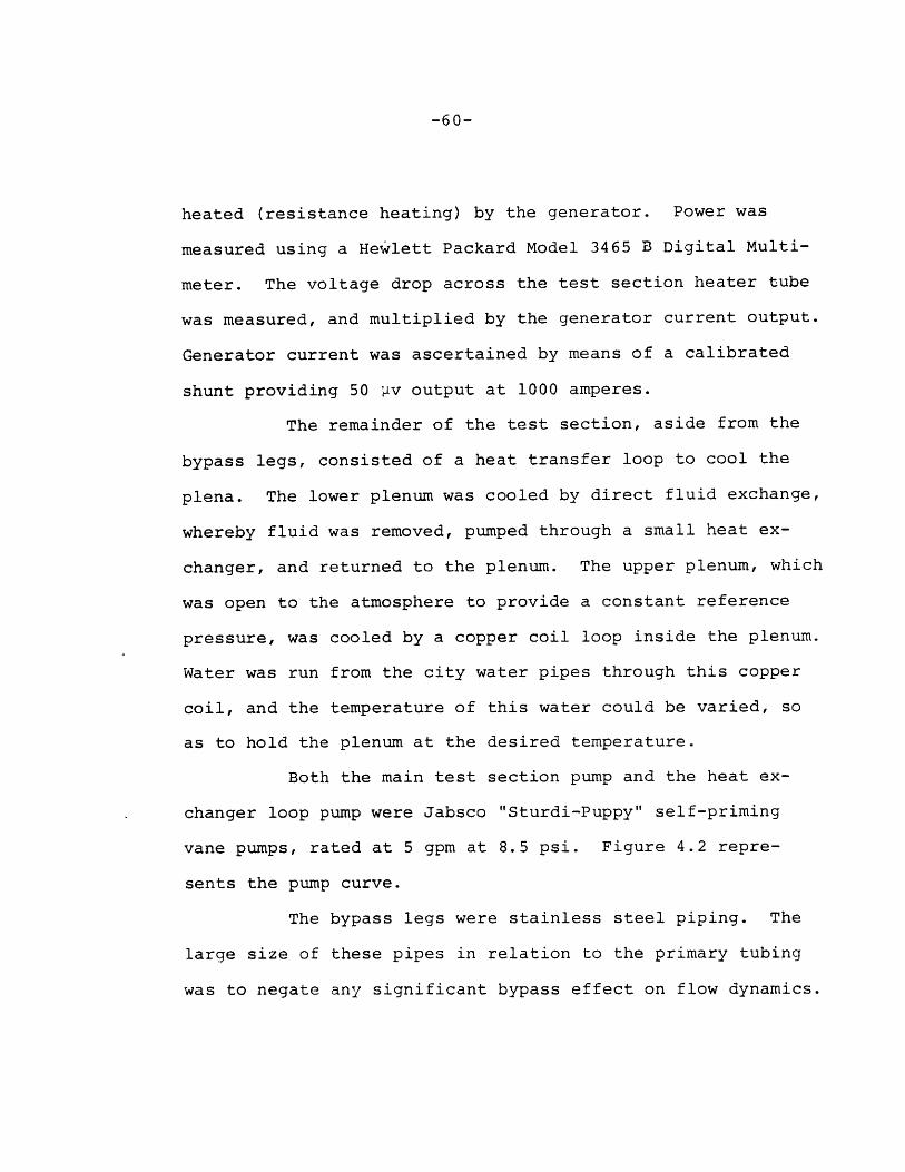
Power was supplied to the test section by a
7 kilowatt DC generator. The test section was directly
-60-
heated (resistance heating) by the generator. Power was
measured using a Hewlett Packard Model 3465 B Digital Multi-
meter. The voltage drop across the test section heater tube
was measured, and multiplied by the generator current output.
Generator current was ascertained by means of a calibrated
shunt providing 50 4v output at 1000 amperes.
The remainder of the test section, aside from the
bypass legs, consisted of a heat transfer loop to cool the
plena. The lower plenum was cooled by direct fluid exchange,
whereby fluid was removed, pumped through a small heat ex-
changer, and returned to the plenum. The upper plenum, which
was open to the atmosphere to provide a constant reference
pressure, was cooled by a copper coil loop inside the plenum.
Water was run from the city water pipes through this copper
coil, and the temperature of this water could be varied, so
as to hold the plenum at the desired temperature.
Both the main test section pump and the heat ex-
changer loop pump were Jabsco "Sturdi-Puppy" self-priming
vane pumps, rated at 5 gpm at 8.5 psi. Figure 4.2 repre-
sents the pump curve.
The bypass legs were stainless steel piping. The
large size of these pipes in relation to the primary tubing
was to negate any significant bypass effect on flow dynamics.

-61-
100.0
10.0
GALLONSPER
MINUTE
1.0
0.10.1 1.0
AP (psi)
FIGURE 4.2 PUMP PERFORMANCE CHARACTERISTICS
10.0

-62-
4.2 Experimental Set-up and Procedure
4.2.1 Pretest Set-up and Calibration
Prior to each set of experiments, several steps
were followed to insure readings from instruments were as
accurate as possible. With the loop filled, the battery
for the Tyco pressure transducers was checked to make cer-
tain it still was charged at 6 volts. The transducers
themselves were then checked for offset from zero. This
was accomplished by checking the output from each trans-
ducer with a digital multimeter to ascertain the output,
and then subtracting from that reading 20 my for each psi
of water head above the transducer.
The second step involved the calibration-in-place
of the Validyne differential pressure transducers. Each
transducer was calibrated in both upflow and downflow.
Calibration in upflow was accomplished via a two step
method. The loop was run at the beginning of the experi-
mental program with the bypass line opened and the power
at a low level. Using the thermocouples directly upstream
and downstream of the heater, a heat balance was performed.
Knowing the amount of power input and the temperature size
of the water across the heater, it was then possible to
determine the flow rate. This single point was used to
calibrate the transducers in upflow, with the assumption

-63-
of linear transducer response. For downflow calibration,
the primary side of the loop was isolated to prevent re-
circulation effect on the transducer. Water was then with-
drawn from the lower plenum through the hole where the plenum
pressure transducer had been mounted in Hinkle's experiment.
Initially, since the water could be withdrawn at variable
rates, several different measurements were made. The flow
was collected for a timed interval, then measured to find
the flow rate. The rate of withdrawal was sufficiently
small, so that the driving pressure on the primary side did
not change appreciably. This insured constant flow over
time. The calibration with several points verified the
linearity assumption made in upflow, and in later calibra-
tions, only one point was taken for downflow calibrations.
The transducers themselves were first bled, and then zeroed
using the carrier demodulator adjusting dial. Output was
again read using a digital multimeter.
Before beginning experimentation, the loop was
operated for several minutes to remove all trapped air
bubbles from the system.
The final step before beginning the experiment
was to load the data acquisition system controller programs
into memory. Once this was accomplished, the data collection
procedure could be started by simply pressing on key

-64-
the system console.
4.2.2 Experimental Procedure
The experimental procedure for each run was basi-
cally the same, with the exception of the final test. The
last experiment will therefore be dealt with separately.
The conditions for all tests analyzed are presented in Table
4.2.
4.2.2.1 Stagnant Flow Testing
Three preliminary tests were run under stagnant
flow conditions to test all of the equipment and to practice
data-taking procedures. Six additional experiments were
then run in which data was acquired and converted.
Preliminary analytical work using the computer
model indicated that the temperature profile in the un-
heated zone was perhaps the single most important parameter
in determining flow oscillatory behavior. It was therfore
decided to run the experiment in the same way each time,
varying only that temperature profile.
The temperature profile was established by running
the loop with bypass flow. This made the velocity in the
primary section sufficiently low that any temperature rang-
ing from the lower plenum temperature to saturation could
be established in the unheated zone by varying heater power.
The temperature would then be uniform from the top of the

-65-
Table 4.2. Experimental Conditions
Test NumberUnheated
Stagnant/ Zone Temperature(oF)Forced Convection Prior to Boiling
Inception
S 75
102
80
100
117
140
%175 decreasingto %95 at top
HeaterPower
(kw)
0.544
0.544
0.209
0.326
0.417
0.390
1.09

-66-
heater to the upper plenum, where the temperature was con-
trolled using the heat transfer loop. Losses to the sur-
roundings were assumed to be negligible. The temperature
of the upper unheated zone was measured by connecting an
Omega Model 403A digital thermometer connected to the first
thermocouple downstream of the heater and in the water.
Once the temperature profile was established, the
pump was stopped and the generator was disconnected from
the heater. The bypass valve was then closed. The flow
path, therefore, consisted of the primary loop with no by-
pass and a stalled pump in the downcomer. The pump was
stalled to permit as little natural circulation as possible
to raise the temperature of the unheated zone. Some leak-
age flow through the stalled pump was present, however.
The power was then set at the desired level and applied in
a step-change fashion to the test section. Shortly before
the inception of boiling, the data acquisition system was
started. Boiling and flow oscillations then were observed
and data acquired. Upon termination of the data acquisition
program in approximately fifteen seconds, the pump was re-
started to bring the loop down below saturation at all points.
Power was then measured using the procedure outlined in a
previous section, and the generator was then shut off. Prep-
arations were then made for the next run.

-67-
After the termination of experimentation, data
reduction was accomplished using the data acquisition com-
puter. A conversion program was written for the instru-
mentation present using calibration information to convert
the Tyco transducer readings to psig and the Validyne trans-
ducer readings to flow rate. The thermocouples were con-
verted by a four step method. Using calibration information
supplied with the RTD temperature reference, the temperature
of the thermocouple termination panel was determined. This
temperature was then converted to millivolts for copper-
constantan thermocouples using a standard curve fit with a
320 F reference power. This number was then added to each
thermocouple reading. Finally, the adjusted thermocouple
output was converted to temperature using a standard curve
fit for a 320F reference temperature. As a last step,
bubble lengths in the heated and unheated zones were calcu-
lated by a stepwise integration of the flow rates with time.
Results of these calculations, and the accuracy of the
derived data, will be discussed in Chapter 5.
4.2.2.2 Forced Convection Testing
One experiment was performed using forced, in-
stead of stagnant, flow. This was done both to examine the
effect of a nonuniform temperature profile in the unheated
zone, and to determine the effect that forced flow would

-68-
the oscillatory behavior. Procedures for pretest calibra-
tion and set-up were the same as described in Section 4.2.1.
In this experiment, though, the run was started with the
bypass closed and the pump running. This generated a flow
rate so large as to make the temperature rise across the
heater very small. The bypass was then opened and data
acquisition began simultaneously. The opening of the bypass
reduced flow drastically to the primary section, allowing
boiling to begin. Termination of the experiment and data
reduction were then performed as outlined in Section 4.2.2.1.
4.3 Safety Precautions
During all tests, the behavior of the bubble was
observed visually in the Pyrex section. This was done to
provide verification of the results derived through data
reduction, and also to insure that the heater was not about
to reach critical heat flux (CHFJ. Since the heater was
clamped at both ends, the rapid heatup of the tube associ-
ated with CHF would have caused severe distortion (bowing)
of the tube, possibly resulting in permanent heater deform-
ation. The Pyrex was also checked to make certain that it
did not crack.
A small amount of leakage was observed, due to
the many fittings as well as the manner in which the thermo-
couples were sealed into the unheated zone. Leaks that were

-69-
small enough to have no appreciable effect on the experiment
were ignored. Large leaks, however, were resealed.

-70-
CHAPTER 5
EXPERIMENTAL AND ANALYTICAL RESULTS
5.1 Experimental Results
5.1.1 Stagnant Flow Tests
5.1.1.1 Data Analysis
Data reduction for each experiment was carried out
as described in Chapter 4. Upon examination of the data,
several facts were immediately evident.
The differential pressure transducer upstream of
the upper plenum was nearly useless in trying to determine
the bubble length in the unheated section. This was true
because of the presence of air in the water. Since the
loop was operated open to the atmosphere, it was not de-
gassed, and the water used to fill the loop had a substan-
tial amount of dissolved air in it. At boiling inception,
this air was stripped out from the steam, and upon conden-
sation, did not dissolve once again into the water, but in-
stead travelled up the test section to the upper plenum.
When these bubbles came near the Validyne transducer, they
so distorted the differential pressure reading that any
attempt to deduce the flow rate or to integrate the flow
rate to find the bubble length yielded unrealistic results,
based on what was observed visually during the experiment.

-71-
In addition, the Validyne transducer just down-
stream of the lower plenum registered extremely large pres-
sure drops at times during each run. This pheonomenon was
attributed to a "water hammer" effect due to vapor conden-
sation. This conclusion was reached due to the fact that
these large pressure drops always occured immediately after
the bubble lengths, as calculated from the flow rate, reach-
ed zero. After peaking rapidly these shock waves would die
away rapidly as well, until the next bubble growth-collapse
cycle. The passage of these pressure waves across the ori-
fice taps at the bottom of the test section caused large
differential pressures to be recorded by the Validyne trans-
ducers, although the flow itself was not significantly af-
fected, due to the high rate of speed of the wave. However,
since flow rates are inferred from the readings of the Vali-
dynes, the response of the transducers to these pressure
waves tended to distort flow rate measurements. No other
distortion, such as that mentioned for the upper transducer
due to air bubbles, was noted for the lower Validyne.
Several examples of experimental results are
shown in Appendix C. The flow rate readings shown in seve-
ral of the tables illustrates clearly the effect of the
"water hammer" shock waves.

-72-
The thermocouples performed rather well, although
there were cases of bead breakage and subsequent failure
to function. In general, though, those couples connected
to the outside of the heater tube tended to respond very
slowly to changes in temperature inside the tube. This is
understandable due to the time lag resulting from the tube
wall thickness. The thermocouples in the fluid, though,
responded rapidly to temperature changes and were quite
valuable in determining bubble movement.
All of the stagnant flow tests exhibited the same
basis characteristics. Upon boiling inception, the vapor
bubble would begin to grow outward in both directions from
the top of the heater. This tended to push warm fluid into
the upper unheated zone, causing the temperature of that
fluid to rise. In addition, condensation would deposit
heat in this fluid. When the bubble grew far enough so that
net condensation exceeded net evaporation, it would then be-
gin to collapse. This, in turn, would pull the colder fluid
above the bubble down into the heated zone, dropping the
temperature at that point below saturation. This cycle was
followed by the aforementioned "water hammer" shock effect,
and then a short waiting period would occur while the water
at the top of the heater was reheated to saturation. This
cycle would repeat itself several times. The amplitude

-73-
and frequency of the bubble growth-collapse cycle tended to
change over the course of the transient, due to the changing
temperature profile in the unheated zone.
In the subsequent sections, each test will be ex-
amined individually in order to discuss its characteristics.
5.1.1.2 Test 4
After the first three preliminary tests, the first
run to be analyzed was number 4.
A plot of calculated bubble lengths in the heater
versus time is presented in Fig. 5.1. Due to the anomalies
in flow rate readings, from which the bubble length is cal-
culated, mentioned in the previous section, these measure-
ments can be treated only as approximate. However, several
pieces of valuable information are discernable from these
data.
The first thing to notice is, in general, the ex-
tremely rapid collapse of the bubbles after they have reach-
ed their peak lengths. This is likely due to the variation
in condensation heat transfer during the oscillation cycle.
This point will be discussed at length in a later section,
due to its importance in determining bubble growth and
collapse.
Although the growth-collapse pattern appears to be
somewhat random at first, after about two seconds, a pattern

30.
25.0
20.0
LB
(In. 15 .
10.
5.
FIGURE 5.1
TIE (Seconds)
RESULTS OF TEST 4 - OSCILLATIONS IN BUBBLE LENGTH

-75-
of increasing and then decreasing bubble length becomes
apparent. This looks very much like a "beat pattern" that
is experienced in sound waves. It results from the super-
position of two somewhat different frequencies. In this
case, it appears that the short frequency is indeed the
bubble oscillation frequency. The longer wave pattern is
probably due to a sort of "enthalpy wave" flow instability.
This instability results, at low flow rates, when a large
amount of fluid is heated to saturation. Upon boiling in-
ception, its density decreases, and the fluid accelerates
out of the heated zone. It is replaced by colder fluid from
below, which increases the density of the fluid once again,
and decelerates the column back to its original condition.
This beat pattern behavior is consistent with results of
liquid metal experiments, another point which will be ex-
amined in more detail in a subsequent section.
The temperature at the first thermocouple in the
fluid downstream of the heater is shown in Fig. 5.2 as a
function of time. This plot clearly illustrates the temp-
erature oscillations which occur as the bubble grows and
collapses.
Another point to note is the waiting period evi-
dent after each bubble collapse. Part of this time is
artifically induced by the pressure waves from the water

220
210
200
190
180
170
160
(°F) 150
140
130
120
110
100
90
80
70
60
FIGURE 5.2 RESULTS OFE (S onds)FIGURE 5.2 RESULTS OF TEST WZ4TEMPERATURE OF FIRST UNHEATED NODE

-77-
hammer effect. However, some of this period is caused by
the necessity to heat the water back to saturation after a
bubble collapses.
A final point to note is the amplitude of the
oscillation. Since the flow rates are inferred from the
pressure transducers, and bubble length is inferred by
integrating the flow rate curve, several sources of uncer-
tainty are available to distort the calculation. In addi-
tion, since the readings from the upper Validyne were highly
unreliable, the bubble length above the heater can be in-
ferred only by applying information gained from the analyti-
cal study. This point will be elaborated upon in the sec-
tion on the comparison of analytical and experimental re-
sults, and when the condensation heat transfer coefficient
is discussed.
5.1.1.3 Test 5
The power to the heater in Test 5 was the same as
that in Test 4; however the temperature in the upper unheated
zone was approximately 250 F higher. The purpose of this run,
then, was to compare it with the previous run to determine
the effect of that temperature on the oscillatory flow be-
havior. A plot of bubble length within the heater versus
time is presented in Fig. 5.3, and temperature of the fluid
just downstream of the heater versus time is shown in Fig.

30.0
25.0
LB
20.0(In.)
15.0
10.0
5.0
0
TrIE (Seconds)
FIGURE 5.3 RESULTS OF TEST 5 - OSCILLATIONS IN BUBBLE LENGTH

-79-
5.4. There are some significant differences between Tests
4 and 5 which should be noted, as well as a few similarities.
The similarities basically relate to the character
of the flow oscillations in general. The same pattern as
that described in the previous section is evident. Some
slight evidence of the "beating" that appeared in Test 4
shows again between about 1.5 and 3.5 seconds. However,
the difference in amplitude is not as significant in Test
5 as in Test 4, a fact that can be attributed to the differ-
ence in unheated zone temperature. A second similarity is
the waiting period between oscillations that was noted in
Test 4. However, this waiting period tends to be shorter
in this test. The higher upper zone temperature means that
less time is needed to return the fluid to saturation.
The main differences between the two runs is the
difference in oscillation frequency and amplitude over the
transient. The average frequency - number of oscillations
divided by transient time - is less in this test than in
Test 4. This difference is especially clear after t=4
seconds. Related to this fact is the slightly larger ampli-
tude of the oscillations. However, the amplitude of the
oscillation is more an inertial effect than a thermal one.
Therefore, while the difference in amplitude is not particu-
larly large, for bubbles of similar lengths in the two tests,

220
T 160 Vf 00
0o
(OF) 150 -
140
130
120
110
100 -
0 1 2 3
TIME (Seconds)
FIGURE 5.4 RESULTS OF TEST 5 - TEMPERATURE OF FIRST UNHEATED NODE

-81-
the collapse time in Run #5 is significantly longer, due to
the lower temperature difference in condensation. This shows
that bubble collapse, in the initial stage at least, is
largely thermal in nature.
The remaining four stagnant flow tests were run at
lower powers than the first two tests. However, no attempt
was made to keep the power exactly the same in the four
tests. The temperature of the unheated zone was increased
from test to test, though, to further explore the influence
of this temperature on flow behavior.
5.1.1.4 Test 6
Conditions during Test 6 featured a very low power
as well as a low temperature in the unheated zone. The re-
sults of this test are presented in Fig. 5.5 and 5.6. The
same general pattern of flow behavior prevails in this test
as in the previous two. The beat pattern is especially
clear between about 2.5 and 6.5 seconds. However, the
amplitudes of the oscillations in this case are smaller
than in the previous tests, a fact attributable mainly to
the extremely low power level. The average frequency of the
oscillations is also much more rapid. This is due partly
to the power level and partly to the low upper zone temper-
ature.
An interesting point to note is that there appears

5
400
LB 3
(In.)
2
0 A •0 1 2 3 4 5 6 7 8 9 10
TIIE (Seconds)
FIGURE 5.5 RESULTS OF TEST 6 - OSCILLATIONS IN BUBBLE LENGTH

220
210
200
190
180
170
T 160f
(oF)150
140 0a
130
120
110
100
90
80
70 -
60 I0 1 2 3 4 5 6 7 8 9 10
TIME (Seconds)
FIGURE 5.6 RESULTS OF TEST 6 - TEMPERATURE OF FIRST UNHEATED NODE

-84-
to be less of a waiting period in this test than in pre-
vious tests. With a low power and low temperature, this is
perhaps the reverse of what would be expected. However,
the low amplitudes of the oscillations in this case mean
that less cold fluid is pulled down during bubble collapse
to mix with the hot fluid at the top of the heater. Even
though the power is low, this decreased mixing effect con-
tributes to a short waiting period. The effect of the low
upper zone temperature is seen primarily in the extremely
fast bubble collapse times. In virtually every cycle, the
collapse rate is quite rapid, creating the asymmetrical
growth-collapse curve. One additional feature to note is
the long temperature coastdown between about 5 and 7 seconds.
This temperature decrease was very likely due to two effects.
First, there was some loss of heat to the environment, and
although those losses were generally quite small, this con-
tributed to the cooling. Second, and more important is the
fact that there was a dense, low temperature column of water
sitting on top of a warmer, lower density region. During
the waiting period, then, colder water diffused into the
warmer zone, causing some cooling to occur. The effect of
this was to increase the waiting period, as seen between
about 6 and 7 seconds in Fig. 5.5.

-85-
5.1.1.5 Test 7
The power and unheated zone temperature for this
test were both higher than their respective values in Test
6. It is perhaps in this run that the features of the flow
behavior that have been discussed previously are most clearly
seen. Figures 5.7 and 5.8 illustrate the bubble growth and
temperature oscillations. In particular, the superposition
of oscillatory patterns to create the "beating" seen in
Tests 4, 5, and 6 is quite evident throughout the run. Not
only does the beat pattern recur, but the beat frequency and
average amplitude of the envelope each increase. This be-
havior is consistent with the higher power and temperature
condition. The average frequency of the oscillation is
slightly less than in Test 6, as is the waiting period be-
tween bubble growth cycle. In addition, the amplitudes of
the oscillations, reflected by the maximum bubble lengths,
are clearly larger.
5.1.1.6 Tests 8 and 9
The last two stagnant flow tests are presented
in Figs. 5.9 through 5.12. In each case, the features dis-
cussed in the previous sections pertaining to bubble growth
patterns, beating,and amplitudes and frequencies can be
seen. The fact that each test essentially reproduces the
same behavior, with changes attributable to slightly differ-

10.
9.
8.
7.LB 6.
(Ln.)
4.
3.
2.
1.
TI1T (Seconds)
FIGURE 5.7 RESULTS OF TEST 7 - OSCILLATIONS IN BUBBLE LENGTH

220
210
200
190 -
T 180f
(OF) 170 -
160 -
I150
140 -
130 -
120 -
110 -
100
90
80 I I I I I I I I0 1 2 3 4- 5 6 7 8 9 10
TIME (Seconds)
FIGURE 5.8 RESULTS OF TEST 7 - TEMPERATURE OF FIRST UNHEATED NODE

13 -
12
11 -
10.
9co
LB 8
(In,) 7
6
5
4
3
2-
100 1 2 3 4 5 6 7 8 9 10
TI IE (Seconds)
FIGURE 5.9 RESULTS OF TEST 8 - OSCILLATIONS IN BUBBLF LENGTH
-UIIIIIC . ~- --

220
210 -
200 -
190 -
180
170T
(OF~160I
150
140
130
120
110 -
100 I I0 1 2 3 4 5 6 7 8 9 10
TIME (Seconds)
FIGURE 5.10 RESULTS OF TEST 8 - TEMPERATURE OF FIRST UNHEATED NODE

20
]I15 - I
L 10
10 --AILB,-(In.)
0 1 2 3 4 5 6 7 8 9 10TIME ( Seconds)
FIGURE 5.11 RESULTS OF TEST 9 - OSCILLATIONS IN BUBBLE LENGTH
__

220
210 -
200 -
190 -
180 -
T 170 HfI
(°F)1 6 0
-
150
140
130 -
120 I I I I I I I I0 1 2 3 4 5 6 7 8 9 10
TIME (Seconds)
FIGURE 5.12 RESULTS OF TEST 9 - TEMPERATURE OF FIRST UNHIEATED NODE

-92-
ing test conditions indicate that the same basic mechanisms
are at work in creating the oscillatory flow behavior.
5.1.2 Forced Convection Testing
Only one experiment was performed with non-stagnant
flow. The results of this experiment are presented in Fig.
5.13. Only the temperature downstream of the heater is shown
for this run, due to the highly ambiguous bubble length re-
sults for this run. The reason for the ambiguous results
will be discussed shortly.
The features discussed in relation to stagnant
flow oscillatory behavior are largely absent in this test,
and the reason for this is quite evident.
The test was carried out by opening the bypass
valve and allowing the flow to coast down from approximately
10-15 feet per second to approximately 0.7 feet per second.
However, during this time, the power was constant at a
level of about 1.09 kilowatts. Under these conditions, the
water in the unheated zone was able to heat up to a sub-
stantially higher temperature than was present in the stag-
nant flow tests. The result of this high temperature at
bubble inception was to allow the growth of the vapor volume
to such an extent that net condensation never exceeded net
evaporation by enough to collapse the bubbles, and steady
state forced convection two-phase flow eventually was

FIGURE 5.13
TIME (Seconds)
RESULTS OF FORCED CONVECTION TEST - TEMPERATURE OF
FIRST UNHEATED NODE
Tf
(OF)
220
210
200
190
180
170
160
150
140
130
120
110
100
90
80
70

-94-
established. This is the reason for the ambiguous bubble
length readings after data reduction. Since no real flow
oscillations occurred, except for the normal variations
associated with "steady" two-phase flow, integration of the
flow rate did not give dependable void readings. In any
case, the vapor present was mainly in the form of small
bubbles, not a single vapor slug. This fact in itself would
indicate a different flow behavior than that present in the
stagnant flow tests. It was believed that setting the power
high enough to allow boiling inception before the establish-
ment of high unheated zone temperatures might possibly lead
to critical heat flux and subsequent damage to the test
section. This was not desirable, and further forced con-
vection tests were not conducted. There were also instru-
mentation problems associated with the forced convection
tests, as well as the same sources of uncertainty as in the
other tests. These will be discussed in the following sec-
tion.
5.1.3 Sources of Error and Uncertainties in Experi-mental Tests
Several factors were present in the experiments
that created, or had the potential to create, errors in the
measurement of key parameters. These factors were differ-
ent in the two different types of experiments, and will be

-95-
examined separately.
5.1.3.1 Stagnant Flow Tests
The sources of uncertainty and error in the stag-
nant flow tests are connected mainly with two factors: the
dissolved air in the water being used, and the water hammer
effects mentioned in Section 5.1.1.
The presence of air on the water has been previous-
ly discussed. After becoming liberated from the water in
boiling, some of the air formed bubbles which travelled up-
ward through the remainder of the test section. As already
noted, these bubbles rendered the flow rate readings from
the upper differential pressure transducer virtually mean-
ingless. However, not all of the air travelled up out of
the test section. Some of it very likely remained mixed
with the steam in the bubble. Upon bubble collapse due to
condensation, the air would remain to cushion the oscill-
ation. Some of the very low amplitude oscillations seen in
the experimental results may indeed be the result of these
air bubbles.
The effect of the water hammer pressure waves on
the flow rate measurements has also been mentioned previous-
ly in Section 5.1.1.2. The extremely high artificial flow
rates inferred from differential pressure measurements dur-
ing these pressure waves certainly distorted the bubble

-96-
length calculations. This effect also made it more diffi-
cult to calculate condensation heat transfer coefficients.
It is also probable that the waiting period between bubble
growth-collapse cycles is partially due to the decay of
these pressure waves, although part of that period is un-
doubtedly genuine. One further possible effect of these
waves involves the measurement of flow rates late in the
course of the transients. In this case, though the waves
generated by the water hammer do tend to decay rapidly,
they also propagate throughout the test section, and would
tend to reflect back and forth from the two plena. It is
possible that, given enough growth-collapse cycles, as
sufficient intensity could still remain to distort flow
rate readings throughout the cycle, and not just at the
beginning and end of the cycles. This may possible account
for the behavior between about 7.5 and 9 seconds in Run 8
(Fig. 5.9), for example.
5.1.3.2 Forced Convection Testing
The uncertainties present in this test are largely
due to an effect related to the water hammer pressure waves
noted in the previous section. When the bypass valve was
opened to permit the flow to coast down, severe pressure
waves resulted from this flow disturbance. As a result,
the flow rate readings inferred from the pressure trans-

-97-
ducers are quite unreliable during the first part of the
transient.
5.1.3.3 Other Sources of Error
In both types of tests, there are sources of error
related to the nature of the instruments themselves. The
Validyne transducers proved to be extremely difficult to
calibrate and to maintain in a zero-output condition at
zero flow. This zero drift was compensated in both the
calibration procedure and in the conversion program, but
some uncertainties were still possible. The Tyco gauge
pressure transducers functioned quite well, in general, and
few uncertainties exist in the readings from these instru-
ments. The thermocouples also functioned well, in general.
However, thermocouples do have characteristic response times,
and cannot record temperature changes instantaneously. The
thermocouples in the fluid responded quite rapidly, and the
readings were considered reliable. The thermocouples fast-
ened onto the outside of the metal tube tended to respond
much more slowly, due to the time constant of the tube
itself, the time constant of the thermocouple, and the con-
tact resistance of the thermcouple bead with the metal tube.
The resultant response time of these thermocouples was some-
what less rapid, and the readings less reliable. Temper-
ature changes related to the flow oscillations were not re-

-98-
corded by these thermocouples.
One final source of error was the data acquisition
system itself. When the RTAS was tested, small offsets-
were found in the output of each channel. These offsets
were subtracted from the instrument readings during data
reduction, but there is no way of knowing if these offsets
were truly constant during a run. In addition, the data
acquisiton system error band as per manufacturer's specifi-
cations was on the order of 0.5%, full scale. This inher-
ent error also contributed somewhat to experimental error.
5.1.4 Calculation of Condensation Heat TransferCoefficient
Examination of the bubble growth-collapse patterns
reveals an extremely asymmetrical behavior. Instead of a
bubble collapse which parallels the growth curve, what is
seen is a relatively long growth period, followed by a
rapid collapse. This indicates a non-uniform heat transfer
coefficient over the bubble growth-collapse cycle. In
order to ascertain the nature of this non-uniformity, sever-
al calculations were performed to determine the condensation
heat transfer coefficient.
Results of the calculations for various experi-
ments are shown in Table 5.1. Details of the calculational
method can be found in Appendix D.

-99-
Table 5.1 Example of Condensation HeatTransfer Coefficients
Test Number Bubble Condition Heat TransferCoefficien(BTU/hr-ft OF)
hA(BTU/hroF)
Growth
Collapse
Growth
Collapse
Growth
Collapse
Growth
Collapse
Growth
Collapse
Growth
Collapse
168.5
3167.1
325.7
4456.3
25.0
192.0
102.4
871.2
102.2
3587.2
109.9
3457.5
6.71
62.71
10.91
180.03
0.19
2.88
0.36
25.53
1.62
100.80
2.86
67.08

-100-
The most interesting aspect of the results is the
extremely large magnitude of the heat transfer coefficient
during bubble collapse. The reason for this behavior in-
volves another type of flow instability. When a vapor
accelerates into a liquid medium, small waves may form at
the liquid-vapor interface. This is due to Taylor insta-
bilities. The waves may then break up into small droplets
of liquid, creating a mist-flow regime at the very end of
the bubble. This type of behavior was documented by Ford
(3) in his Freon experiments. Since the heat transfer co-
efficient shown is based on an area which does not account
for any such mechanisms, the result is a coefficient which
is quite large. The important parameter is the product of
the heat transfer coefficient and the heat transfer area,
and this is also shown in Table 5.1. This product repre-
sents the heat removal rate (q/AT). The calculational
method employed to determine the heat removal contains
some assumptions, as presented in Appendix D, which might
tend to distort the actual numbers; however, the way in
which the condensation changes over the period of the
bubble growth-collapse cycle is indisputable.
The fact that the heat transfer coefficient effects
the oscillatory behavior of the system implies that a cir-
cular situation exists; that is, that the system behavior

-101-
in turn affects the heat transfer coefficient. The more
violent the oscillation, the greater the acceleration of
vapor into fluid, and the more extensive the fluid misting
effect becomes. This is one reason for the behavior noted
in Test 6 - the oscillation amplitude was so small and vapor
generation reasonably slow, that the heat transfer coeffi-
cient did not have a chance to increase to the same magni-
tude as in the higher-power experiments.
Although it is qualitatively clear what is happen-
ing to the heat transfer coefficient in this type of flow,
quantifying the behavior mechanistically is more difficult,
and was not conceived as part of this work. Further dis-
cussion of this point can be found in Chapter 6.
5.1.5 Comparison of Water Data to Sodium Data
Although the Sodium Boiling Test Facility was not
able to operate in a mode precisely comparable to the WTL,
is is interesting to compare the results of the water ex-
periments to LOPI experiments carried out in the THORS
facility at ORNL. It should be noted that the THORS faci-
lity is a multipin bundle, in which two-dimensional effects
may be important. However, examination of the results of
one of the LOPI tests reveals some interesting parallels.
Figure 5.14 shows the results from THORS test
71H-101. Note that the parameter plotted is flow rate

-102-
Io~ I -[, -I0 II "I
10.0
-0.O -1H
0.0 5.0 10.0 15.0 20.0 25.0 30.0 35.0 0.0 4O5.Q 50.0 55.0 60.0SECCNIS
THNR567. 329/77 13 25 32 rESf 71H ItuN 101
FIURE 3.14 EX LE 'OF IORPS ESULTS - O).,.ETMIPJC F T 7
OSCILLATIONS

-103-
versus time; however, since the flow oscillates about the
zero-flow point, it is clear that the integration of the
curve to show the bubble length would show the same charac-
teristics. The most outstanding point is the beat pattern
that appears during the course of the oscillation cycle.
This characteristic is quite similar to the pattern seen in
several of the water tests. In addition, there is a change
in flow oscillation frequency over the transient, which
again parallels the water results.
One other area in which a comparison between water
and sodium tests can be drawn is the subject of nonconden-
sable gases. Mention has already been made about some of
the effects on dissolved air in the water. It must be
noted that in a sodium system, inert gas blankets are used
to preclude the potentially dangerous contact of sodium and
oxygen. As a result, these gases become dissolved in the
sodium, and can behave in much the same manner as air in
water. Sodium systems cannot be examined visually during
experimentation, of course, to determine the presence of
inert gas in the sodium vapor; however, the presence of non-
condensables in water experiments should not be considered
as a non-prototypic parameter.
5.2 Analytical Results
The results of computer simulations of the stag-

-104-
nant flow tests are presented in Fig. 5.15 through 5.33.
The features of the simulations themselves will be discussed
in the next section. Comparison of analytical results to
those obtained experimentally will be discussed in the
Section 5.2.2.
5.2.1 Features of Analytical Simulations
The information obtained from a computer run in-
cludes data on flow rates, bubble pressures, areas, and
bubble lengths and volumes. An example of the actual out-
put from the computer is presented in Appendix E. There
exists, as part of the program, a subroutine which picks
specific pieces of information and plots them, using a
library plotting routine. Examples of these plots are pre-
sented in Figs. 5.15 through 5.18. The conditions for this
run correspond to those shown in the output in Appendix E.
Some of the features to be noted in the plots in-
clude the rapid oscillation of all variables plotted as the
bubble flows and collapses. Note also, the slight delay
between oscillatory cycles and the asymmetric pattern of
the growth-collapse cycle.
Figures 5.19 through 5.21 present a slightly
different perspective. In these plots, the bubble length
within the heater is shown. The conditions for these runs
correspond to some of the stagnant-flow test conditions.

4 F I I It-"1
+* 3
x 2 -U
c-nNITi 2
+ 2S 0
Q 0n
W22H -1- 0!II -2 " 2 -0 ,
LL2 21. -3-0
-4
0 2 4 G 9 i0 12
TIME (SEC)FIGURE 5.15 CCUPUThr (M]ffTE PIR - TLUATIMA (' T ERP 9: VOILETRIC TOVW RATES IN
LEGS 1 AND 2

22
2 0
--, 18H
LU
oncr- ,h lLiU 14
12 -
100 2 4 G 9 10 12
TIME (SEC)FIGURE 5,16 COMPUTER GENERATED PLOT , SIMULATION OF TEST 9: BUBBLE PRESSURE

3.0
2.5 -
,.., 4o~nLU 2.0(IzZH 4
1.5I IC3Dzi 1.0
E4-I
~0.5
0.00 2 4 G 9 j0 12
TIME (SEC)
FIGURE 5.17 COMPUTER GENERATED PLOT - SIMULATION OF TEST 9: TOTAL BUBBLE LENGTH

1.5 1I I
zu0.51.0
LII 1 0 ) L
Lu -0.5
-1.0 zI
-1.5
0 2 4 6 9 i0 12
TIME (SEC)FIGURE 5.18 COMPUTER GENERATED PLOT - SIMULATION OF TEST 9: BUBBLE LENGTHS IN LEGS
1 AND 2.

- h = 1500 BTU/hr-ftL°Fcon
2.0
LB
C)(In.)
1.0
I I
1.0 2.0 3.0 4.0 5.0TIME (Seconds)
FIGURE 5.19 COMPARISON OF ANALYTICAL RESULTS FOR DIFFERENT HEAT TRANSFER
COEFFICIENTS - TEST 4 CONDITIONS

1.5
1.0 1'
II
LB
(In,)0.5 1i
0III I I
1.0 2.0 3.0 4.0 5.0 6.0
T]E (Seconds)
FIGURE 5.20 COMPARISON OF ANALYTICAL RESULTS FOR DIFFERENT HEAT TRANSFER
COEFFICIENTS - TEST 6 CONDITIONS
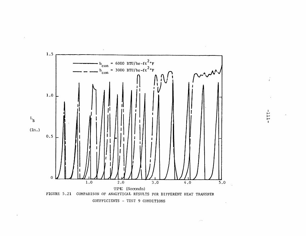
1.5
1.0
LB
(In.)
0.5
0
FIGURE 5.21
1.0 2.0 3.0 4.0
TIBE (Seconds)COMPARISON OF ANALYTICAL RESULTS FOR DIFFERENT HEAT TRANSFER
COEFFICIENTS - TEST 9 CONDITIONS
5.0

-112-
However, the condensation heat transfer coefficient has been
varied so as to provide a comparison between the results for
different heat removal rates.
It is not surprising that, when a high heat trans-
fer coefficient is used, the cycle period is slightly smaller,
and the amplitude of the cycle is considerably smaller. This
is due largely to the manner in which the code is currently
set up.
When the temperature nodal pattern is input to the
code, the first node is normally made quite small - on the
order of an inch - and the temperature therein is set at sat-
uration. This permits no condensation to occur in that node.
This is done for two reasons. First, from a physical stand-
point, some hot fluid must flow into the unheated zone be-
fore the inception of boiling, due to natural circulation.
The resistance of the stalled pump during the stagnant flow
tests, however, made the natural circulation flow rate quite
small. Therefore, this relatively small volume of fluid
was used as a saturated length. This "zone of no condensation"
permits growth of the bubble at the start of the cycle. In
addition, the heat transfer coefficient, when input as a
constant, as was done in these runs, must be set very high,
to correspond to the large heat removal rate attained dur-
ing bubble collapse. The small initial saturated node pro-

-113-
vides a de facto variation in condensation heat transfer co-
efficient. More preferable, of course, would be a mechan-
istic model of the variation of the heat transfer coefficient
during the cycle. However, such a model does not presently
exist.
The choice of the length of the saturated node
and the condensation heat transfer coefficient together
provides a "dial" which the user may adjust. The combin-
ation of these two parameters, along with the temperature
profile chosen for the unheated zone, legislates, for all
intents and purposes, the length of the bubble during the
transient. Changes in the temperature profile by virtue
of the heat input to or output from the unheated zone dur-
ing the transient also provide some change in the cycle
period and amplitude, and this, too, is demonstrated in all
of the figures.
The variation of the heat transfer coefficient
during the cycle in the simulations is correct in a broad
sense - low at the beginning and high at the peak, and it
was felt that trying to vary either the temperature profile
or the heat transfer coefficient without some mechanistic
base would cause more difficulties than it would solve.
The results of this decision are discussed in the next sec-
tion.

-114-
5.2.2 Comparison of Analytical and ExperimentalTest Results
The parameter which is best suited for comparison
between the experimental tests and analytical simulations
is the bubble length with the heater. This is true for a
combination of reasons. First and foremost, this bubble
length is the most reliable nonthermal datum that can be
derived from the experimental results. The experimentally
determined flow rates were subject to effects that do not
show up analytically (non-condensables, "water hammer", etc.).
Second, this parameter illustrates quite clearly the fre-
quency, amplitude, and asymmetrical behavior of the oscill-
ations.
The bubble length within the heater is plotted,
therefore, in Figs. 5.22 through 5.27, for each stagnant
flow test and its corresponding computer simulation. The
simulations plotted here correspond to the high heat trans-
fer coefficient runs, examples of which were shown and ex-
plained in Section 5.2.1. One small change has been made,
however: the waiting period between oscillations has been
adjusted in the analytical results to agree with that de-
termined experimentally. Therefore, what is shown is
actually a cycle-by-cycle comparison of the results.
The reason for the adjustment involves the method

30.0
25.0
Experimental Data
20.020 -Computer Simulatio9,
h = 3000 BTU/hr-ft Fcon
LB 15.0 u
I
(In.)
10.0
5.0
1 2 3 4 5 6 7 8 9 10TIME (Seconds)
ANALYTICAL VS. EXPERIMENTAL RESULTS - TEST 4:
__
BUBBLE LENGTHFIGURE 5.22

TIME (Seconds)FIGURE 5,23 ANALYTICAL VS. EXPERIMENTAL RESULTS - TEST 5: BUBBLE LENGTH
30.0
LB
(In.)
25.0
20.0
15.0
10,0
5,0
0

LB
(In.)
TI2E (Seconds)
FIGURE 5.24 ANALYTICAL VS. EXPERIMENTAL RESULTS - TEST 6: BUBBLE LENGTH
3 L- IL -I__I

0 1 2 3 4 5 6 7 8TIME (Seconds)
FIGURE 5.25 ANALYTICAL VS. EXPERIMENTAL RESULTS - TEST 7: BUBBLE LENGTH
10 .1
9.1
8.
7.'
L 6.1LB
5.1
(In.)4.
3.
2.
1.
9 10
__ __

15
14 - Experimental Data
13 - Computer Simulation,h = 4000 BTU/hr-ft 2OF
12 - con
11
10
L 9B)8 H8-
(In.)
7
6
5
4
3
2
1 ___1 ' A i 4'
01 2 3 4 5 6 7 8 9 10
TIME (Seconds)
FIGURE 5.26 ANALYTICAL VS. EXPERIMENTAL RESULTS - TEST 8: BUBBLE LENGTH

LB
10
(In.)
TI4E (Seconds)
FIGURE 5.27 ANALYTICAL VS. EXPERIMENTAL RESULTS - TEST 9: BUBBLE LENGTH

-121-
by which the waiting period is determined in the code. The
program uses the First Law of thermodynamics to increment
the temperature of the initial node back to saturation.
However, the temperature after bubble collapse is determined
by mixing an arbitrary amount of fluid at saturation with
the colder fluid from above the heater. While this arbit-
rary amount of fluid is chosen from the standpoint of how
much physical mixing can occur, it is essentially another
user-adjustable "dial". In addition, the large positive
flow rate readings produced by the "water hammer" effect
probably had a tendency to bias the calculations of bubble
length to some extent. This would have shown up most in
the waiting period between cycles, due to the decay of
these pressure waves. In light of these facts, it was felt
that to try to adjust the code to correspond to the actual
experimental output would not be a productive exercise.
To demonstrate how the actual computer output corresponds
to the experimental results, Fig. 5.28 has been included on
the following page. This is a combination of Fig. 5.11 and
Fig. 5.18, and plots length versus time, calculated without
adjusting the delay time against the experimental data.
The difference in calculated versus experimental period can
also be deduced by examining the temperature versus time
plots in Fig. 5.29 through 5.34.

LB
10-
(In.)
5-
5AAS1 2 3 4 5 6 7 8 9 10
TI7.E (Seconds)
FIGURE 5.28 ANALYTICAL VS. EXPERIMENTAL RESULTS - TEST 9: BUBBLE LENGTHS, NO DELAY
TIME ADJUSTMENT
-123-
In every case, the first and most obvious fact
that is apparent is that the experimental results give much
larger bubble lengths than the analytical results. The
reasons for this are twofold. First, the previously men-
tioned bias in the experimental flow rate readings, due to
pressure waves, tends to distort the bubble lengths deter-
mined from those readings. Second, the way in which the
condensation heat transfer coefficient varies, both experi-
mentally and analytically, has been discussed in previous
sections. Although the variations in heat transfer coeffi-
cient throughout the entire cycle have not been accounted
for analytically, it is interesting to note that, in almost
every case, the initial rise of the bubble growth pattern
is very close analytically to what is seen experimentally.
This confirms the lack of condensation during this period
of the cycle. In a few cases, in Test 6 especially, the
entire cycle is very closely simulated, as well. This
would tend to confirm the large jump in condensation heat
transfer when the bubble begins to collapse. Other tests
are more correct qualitatively, though. The fact that
there is a mismatch in the experimental and analytical heat
transfer coefficients during various times of the cycle ex-
plains much of the quantitative disagreement between the
two types of results.

-124-
Figures 5.29 through 5.34 show the temperature
of the first fluid thermocouple in the experiment compared
to that of the first non-saturated analytical node, for each
stagnant flow test. Note that while the values of the tem-
peratures are not correct quantitatively, in every case, and
that the flow oscillatory patterns are somewhat variant, the
trends between experimental temperature results and computer
simulations agree quite well.
From a qualitative standpoint, then, the analy-
tical results and the experimental results agree quite well.
In general, the period of the oscillatory cycles, as well as
the asymmetric shape of the cycle curve are in close agree-
ment. In addition, the variation of the amplitude and period
during the transient agree fairly well. Due to the large
uncertainties in the experimental results, this qualitative
agreement in the areas mentioned are much more important than
the quantitative disagreement in the actual magnitude of the
parameters measured.

TIME (seconds)
FIGURE 5.29 A MIr FTICIL VS. EXPIERT! iTAL RESULTS - TEST 4: UNHEATED ZONE TPERAIJRE
Tf
(oF
220
210
200
190
180
170
160
150)
140
130
120
110
100
90
80
70
60

TIME (Seconds)
FIGURE 5.30 ANALYTICAL VS. EXPERIMENTAL RESULTS - TEST 5: UNTHEATED ZONE TEMPERATURE
Tf
(0CF
220
210
200
190
180
170
160
)50
140
130
120
110
100
90

220
210 -
200 -
190 -
180 A4A ..170 L
160
150I
Tf 140
(OF) 130
120 - p110 Experimental Data
100Computer Simulation, 2
90 h = 2000 BTU/hr-ft oFcon
80
70
60 I I I j I I 1 I I0 1 2 3 4 5 6 7 8 9 10
TIME (Seconds)
FIGURE 5.31 ANALYTICAL VS. EXPERIMENTAL RESULTS - TEST 6: UNHEATEDZONE TEMPERATURE
- - I - I -- I-C ~-i I12 r

220
210 -
200 ._ .
190 -
180 -
170 -
160
T 150f
(OF) 140
_ '130 Experimental Data
120 Computer Simulation
h = 3000 BTU/hr-ft OF
110 con
100
9080 I .I I I I I I I I
0 1 2 3 4 5 6 7 8 9 10
TIME (Seconds)
FIGURE 5.32 ANALYTICAL VS. EXPERIMENTAL RESULTS - TEST 7: UNHEATEDZONE TEMPERATURE

//t
Experimental Data I
Computer Simulationh = 4000
BTU/hr-ft oF
2 3 456TIME (Seconds)
FIGURE 5.33 ANALYTICAL VS. EXPERIMENTAL RESULTS - TEST 8: UNHEATEDZONE TEMPERATURE

220
210
200
190
180
Tf 170 -(f)1 76 0
__ Experimental Data1o60-(OF)
1 6
150 - . .. Computer Simulation, 2140 h = 6000 BTU/hr-ft °F •
con
130 -
120 I I I I I I I I I
0 1 2 3 4 5 6 7 8 9 10TIME (Seconds)
FIGURE 5.34 ANALYTICAL VS. EXPERIMENTAL RESULTS - TEST 9: UNHEATEDZONE TEMPERATURE
_ ________ _~

-131-
CHAPTER 6
CONCLUSIONS AND RECOMMENDATIONS
FUTURE STUDY
6.1 Conclusions
The results of the experimental and analytical
work performed for this project have led to the following
conclusions.
1. A model has been developed which will qualitativelydescribe the processes occurring during flow oscil-lations of the type studied.
2. Experiments with water indicate that sodium behav-ior can be successfully simulated using water, des-pite the large disparity in the physical makeupand properties of the two liquids.
3. A set of criteria has been proposed whereby waterand sodium data can be compared. Only a verylimited amount of mostly qualitative testing ofthese criteria has been done as part of this work,however.
4. The temperature profile in the unheated regiondownstream of the source of heat for the fluid(i.e. core, heater pin, heater tube) has a signi-ficant effect in determining the behavior of thesystem during oscillations.
5. The heat transfer coefficient for condensationalso has a significant effect on the flow oscill-ations. In addition, the coefficient changes overperhaps two orders of magnitude during the oscill-ations, due to the microscale processes at theliquid-vapor interface, and this change may be oneof the driving forces during oscillatory behavior.
6. The existence of flow oscillations helps to drawcool fluid down from the unheated zone into thetop of the heated zone. This behavior may well

-132-
delay dryout of the heater walls and any subsequenttemperature excursions, which might otherwise provedetrimental to providing adequate core cooling dur-ing transients.
7. More study is needed in many of the areas delineatedin points 1-6.
6.2 Recommendations for Future Work
The scope of this project was such that it did not
allow detailed study of the condensation heat transfer co-
efficient. The type of behavior seen was not completely
anticipated, and the experiment was not constructed in a
way which would easily lead to the development of a mechan-
istic model of the condensation process during flow oscill-
ations. Clearly, further work is needed in this area.
The criteria proposed for the comparison of sodium
and water data have been tested only superficially. It
would be useful if the SBTF experiment at ORNL were to be
operated in such a way that low-power, low-flow oscillations
could be generated for comparison to WTL results. Data from
THORS and the multipin experiments is useful from a qualita-
tive standpoint, but the existence of two-dimensional effects
due to the radically different experimental geometry may
distort efforts to quantitatively compare the data.
The model which has been developed for this pro-
ject makes a good start toward describing, from a physical
basis, the parameters which affect flow oscillatory behavior.

-133-
However, it is far from complete, especially with respect
to the heat transfer calculational scheme. Further work is
required on the model in this area, as well as in the area
of expanding the model to a multidimensional tool. A con-
siderable amount of work is underway presently to determine
whether multidimensional effects exist in large LMFBR fuel
pin bundles. The existence of a multidimensional model to
aid in this work would be helpful, and consistent with the
original objective of this work to provide a model which
might become a module in a large systems code.
Experimentally, there appears to be a wide range
of options regarding the simulation of sodium behavior using
water. It is clear that certain types of flow behavior can
be modelled using water instead of liquid sodium, namely,
those types which depend mainly on hydrodynamic processes,
rather than thermal ones. Consideration must be given to
using small scale water experiments for preliminary investi-
gations of sodium behavior, so that otherwise unexpected
effects which might have an adverse effect on sodium experi-
ments may be avoided.
Further work on the effect of loop dynamics on
flow behavior should be performed. The means to do this
on the Water Test Loop currently exists to some extent,
using variable flow orifices in the orifice flange upstream

-134-
of the inlet plenum. A parametric study using the FLOSS
model might also be valuable.
Finally, more work is needed in quantifying the
effect of unheated zone temperature profiles on flow oscill-
ations. Judging from the experimental results obtained in
this work, there may, for a certain power, be an optimum
temperature profile which would provide the best means of
accident abatement. The design of LMFBR cores so that such
effects could be used to maximum advantage would be the
ultimate result of such future work.

-135-
REFEREUCES
1. W.D. Hinkle, et.al., "LMFBR Safety and Sodium Boiling,
A State of the Art Report", Department of Energy (June,
1978).
2. R.J. Ribando, et al., "Sodium Boiling in a Full Length
19-Pin Simulated Fuel Assembly (THORS Bundle 6A)",
ORNL/TM-6553, Oak Ridge National Laboratory (January,1979).
3. W.D. Ford, "Bubble Growth and Collapse in Narrow Tubes
with Nonuniform Temperature Profiles", ANL-7746, Argonne
National Laboratory (December, 1970).
4. W.D. Hinkle, "Water Tests for Determining Post Voiding
Behavior in the LMFBR", M.I.T. Report MIT-EL-76-005,
M.I.T. Energy Laboratory (June, 1976).
5. P.W. Garrison, R.H. Morris and B.H. Montgomery, "Dry-
out Measurements for Sodium Natural Convection in a
Vertical Channel", ORNL/TM-7018, Oak Ridge National
Laboratory (December, 1979).
6. R.W. Bowring, "HAMBO: A Computer Programme for the Sub-
channel Analysis of the Hydraulic and Burnout Charac-
teristics of Rod Clusters", AEEW-R 582, UKAEA (1968).
7. A.E. Levin, "Simulation of Flow Behavior in BWR Coolant
Channels During Transients", S.B. Thesis, M.I.T. (June,
1975).
8. G.H. Golden and J.V. Tokar, "Thermophysical Properties
of Sodium", ANL-7323, Argonne National Laboratory(August, 1967).
9. Perkin-Elmer Computer Systems Division, "OS/16 Opera-
tor's Handbook", Perkin-Elmer Corporation (1975).
10. Perkin-Elmer Computer Systems Division, "OS/16 User's
Handbook", Perkin-Elmer Corporation (1976).
11. Perkin-Elmer Computer Systems Division, "FORTRAN IV
Reference Manual and User Guide", Perkin-Elmer Corpor-
ation (1976).

-136-
12. Perkin-Elmer Computer Systems Division, "FORTRAN IVRun Time Support", Perkin-Elmer Corporation (1977).
13. J. Aberle, et al., "Sodium Boiling Experiments in a 7-Pin Bundle under Flow Rundown Conditions", KFK 2378,GFK, Karlsruhe, FRG.
14. A.E. Bergles, "Review of Instabilities in Two-PhaseSystems", Proc. NATO Advanced Study Institute in TwoPhase Flows and Heat Transfer, V.1, Hemisphere Publish-ing Corp., Washington, D.C. (1977).
15. J. Costa and P. Charlety, "Forced Convection Boiling ofSodium in a Narrow Channel", in Liquid Metal Heat Trans-fer and Fluid Dynamics, A.S.M.E. (1970).
16. A.W. Cronenberg, "A Thermohydrodynamic Model for MoltenUO2-Na Interaction, Pertaining to Fast-Reactor Fuel-Failure Accidents", ANL-7947, Argonne National Labora-tory (June, 1972).
17. M.H. Fontana, "THORS Bundle 6A Boiling Stability TestResults", Report presented at D.O.E. Conference, Boston(August, 1977).
18. P.W. Garrison, SBTF Test Results, Personal Communication(January, 1979).
19. R.E. Henry, et al., "OPERA Single-Pin Coastdown Expulsionand Reentry Test", ANL-75-17, Argonne National Laboratory(February, 1975).
20. W. Kowalchuk and A.A. Sonin, "A Model for CondensationOscillations in a Vertical Pipe Discharging Steam intoa Subcooled Water Pool", NUREG/CR-022, M.I.T. (June,1978).
21. W. Peppler and E. G. Schlechtendahl, "Experimental andAnalytical Investigations of Sodium Boiling Events inNarrow Channels", Proc. Winter Annual Meeting, ASME,in Liquid Metal Heat Transfer and Fluid Dynamics,A.S.M.E. (November, 1970).

-137-
22. M. Pezzilli, et al., "The NEMI Code for Sodium Boiling,and its Experimental Basis", in Liquid Metal Heat Trans-fer and Fluid Dynamics, A.S.M.E. (1970).
23. T.A. Shih, "The SOBOIL Program - A Transient, Multi-channel, Two-Phase Flow Model for Analysis of SodiumBoiling in LMFBR Fuel Assemblies, G.E. ST-TN-79008,General Electric Corp., A.R.S.D.
24. M.G. Stevenson, et al., "Current Status and ExperimentalBasis of the SAS LMFBR Accident Analysis Code System",CONF-740401-P3, Proc. Fast Reactor Safety Mtg., BeverlyHills, CA (April, 1974).
25. D.H. Thompson, et al., "SLSF In-Reactor Experiment P3A-Interim Post-Test Report", ANL/RAS 77-, Argonne NationalLaboratory (November, 1977).
26. J.G. Collier, Convective Boiling and Condensation, Mc-Graw-Hill Book Company, LTD, London (1972).
27. R.H. Sabersky, A.J. Acosta, and E.G. Hauptmann, FluidFlow, 2nd Ed., The MacMillan Co., New York (1971).
28. W.M. Rohsenow and H.Y. Choi, Heat, Mass and MomentumTransfer, Prentice-Hall, Inc., New Jersey (1961).
29. M. Clark, J. and K.F. Hansen, Numerical Methods ofReactor Analysis, Academic Press, New York (1964).
30. R.H. Perry and C.H. Chilton, Eds., Chemical Engineers'Handbook, 5th Ed., McGraw Hill Book Company, New York(1973).
31. R.L. Powell, et al., "Thermocouple Reference TablesBased on the IPTS-68", NBS Monograph 125, U.S. NationalBureau of Standards (March, 1974).
32. F.E. Dunn, et. al., "The SAS2A LMFBR Accident AnalysisComputer Code," ANL/RAS 73-39, Argonne National Labora-tory (December, 1973).
33. R.E. Barry and R.E. Balshizer, "Condensation of Sodiumat High Heat Fluxes," Proc. 3rd Int. Heat Transfer Conf.,V.II (1966).

-138-
APPENDIX A
THE COMPUTER CODE FLOSS
A.l. General Description of the Code
The computer code FLOSS is a relatively small and
simple program designed to solve the equations for the hydro-
dynamic and thermal models. It was developed as part of this
project, and is envisioned as a module of a large system-scale
code at some future time. Because of this ultimate aim,
many complicating features, such as sophisticated heat trans-
fer models, were omitted. In addition, since the model deals
only with a fixed regime, single phase flow before the trans-
ient and two-phase flow after the transient have not been
modelled. Instead, the primary aim was to develop a code
which could be easily understood and would take small amounts
of computer time to run, yet would include as much of the
essential physics of the problem as possible. This aim has
been, for the most part, achieved.
A.2. Solution of the Hydrodynamic and Thermal Models
The solution scheme for the equations presented
in Chapter 2 is an amalgam of different techniques for
finite difference solutions of differential equations. The
entire code is semi-implicit, with an iterative scheme des-
cribed in Chapter 2.

-139-
A.2.1 The Hydrodynamic Model
The equations for the hydrodynamic model are:
dQlAP' = I d + R I'Q 2 (2.28)
1 dt 1 1
d2 2AP' = I dQ2 + R 'Q2 (2.29)
2 dt 2 2
V dpQ= 2 ' (2.11)3 p dt
g
The first two equations are solved using a first-
order, explicit finite difference scheme. The equations can
be rearranged into the form
dQ2 AP ' Q 2Q (A.1)at 2
where i can be either 1 or 2.
This is then transformed into a finite difference
equation:n n-n
Qi - Qi AP'n R'n-1 n-1 2 (A.2)= ___ (Qn-l) 2 (A.2)(Q)At n n i
1 1
where n is a time index.
The final form of the equation, upon rearrange-
ment of terms, is

-140-
n n-1 At 'n 'n-1 n-12Qi = Qin- + [APn - R. (Q. )] (A.3)
1 1 'n 1 1I.
Equation (2.11) is solved by an implicit, first
order finite difference approximation
n n n-i (A.4)
3 n Atg
Because of the explicit nature of the equations
solved by Eq. (A.3), special attention must be paid to the
time step. The time step size is limited by the Courant
condition
Ax > v (A.5)At -
That is, the time step must be small enough that the velo-
city does not allow the calculation to cross more than one
node. This becomes important during the temperature profile
calculation in the unheated zone. During condensation, the
rapidity of the bubble collapse creates extremely large velo-
cities, relative to the bubble growth period. For this rea-
on, a variable time step is employed in the solution of Eq.
(A.3). If the solution fails to converge at a large time
step, the step is reduced by a factor of two, and the solu-
tion procedure is repeated. If convergence is not achieved

-141-
after several successive reductions, it is assumed the bubble
has collapsed entirely or undergone an expulsion. The method
for dealing with this problem is discussed in Section A.3.1.
A.2.2 The Thermal Model
The equation for the thermal model is
V dPQ (n + g )/ph (2.27)
S net dt g fg
This equation is also solved by an implicit, first-
order finite difference approximation
n n n pn - Pn- n nQ = [q + V ( n)]/(p h ) (A.5)
s net g At g fg
A.3 The Structure of the Code
To provide ease of handling and understanding,
the code is split into a main section and several subroutines.
Each routine is briefly explained in this section.
A.3.1 FLOSS-MAIN Program
The MAIN portion of the code provides the basic
framework for the simulation of transients. In addition,
schemes for variable time step size and non-convergence
restarting are included. Initially, data are input and con-

-142-
verted to an internally consistent set of units, a proper
call sequence for the actual calculational subroutines is
established, initial conditions are established, and output
is arranged to be easily readable.
One of the limitations that has been determined by
use of the code is the necessity to generate a sufficient
amount of vapor during the initial time step of the transient.
By trial and error, the amount of power required for this
to occur is such that
(Input Power) * (time step) - 0.025 kw-sec (A.6)
This is the only initial constraint. However, for
very low powers, large initial time steps must be used. The
code, through the variable time step calculation, will adjust
the size of the time step as necessary to allow convergence.
If convergence does not occur, as described in
Chapter 2, that is, if the thermal and hydrodynamic models
cannot be made to generate the same bubble size, a check is
made of the temperature in the initial node downstream of
the heater. If this temperature is below the saturation
temperature at initial pressure, as is usually the case, it
is an indication that the bubble has collapsed entirely,
and the calculation is restarted. This is accomplished by

-143-
assuming that a small amount of fluid at the top of the heater,
originally at saturation, is mixed with the lower temperature
fluid in the first unheated node. The mean temperatures of
this fluid is then determined, and a heat balance is per-
formed on this fluid, using the heater power as a heat source.
The temperature of the fluid in this node is thereby increas-
ed, while temperatures in the upper nodes of the unheated
zone are held constant. When the temperature in the first
node reaches saturation, the calculation of the transient
proceeds anew. In this way, the "waiting period" seen ex-
perimentally is reproduced.
If the temperature of the initial unheated node
is greater than or equal to saturation at nonconvergence, it
is assumed that an expulsion of fluid has occurred, and the
transient is ended at that point.
A.3.2 Subroutine HYDRO
This subprogram solves the hydrodynamic model, as
previously outlined in A.2.1. The differencing scheme is
established, as well as the iterative scheme for calculation
of the bubble lengths and volumes. Error convergence limits,
read in as data, are applied in this routine.
A.3.3. Subroutine HEAT
This routine solves the thermal model, as previous-
ly described. The bubble is split into two volumes, one in

-144-
the heated zone and one in the unheated zone. The heat in-
puts and outflows are calculated separately for each "half-
bubble", and the total size is then determined. Convergence
criteria are set up such that not only must the total bubble
size be consistent, but the two separate zones must also
converge. There also exists the means to account for wall
heat capacity effects.
In addition, the unheated zone temperature profile
is calculated. The method for this calculation is quite in-
volved, and the code listing should be referred to in order
to understand the details of the scheme. To summarize the
scheme, a search is performed to locate the vapor-liquid
interface at each time step. That having been accomplished,
the temperature of each node is then calculated on a volume-
averaged basis:
n-1n n-l n n-l At i/
T. = (T V. + T. dV .. + n- n- ) / V1 1 1 1 13 n-l n-l i
p Cp(A.7)
In Eq. (A.7), i and j represent the volume being
calculated and the adjacent volume respectively. This vol-
ume is either above or below volume i, depending on whether
the bubble is expanding or contracting. The term T. n-Vi .n1 1
represents the temperature of the node at the previous time
step multiplied by the volume of that fluid remaining in

-145-
the node at the current time step. The second term repre-
sents the temperature of the adjacent node, multiplied by
the amount of fluid pushed from node j into node i by bubble
movement, and the final term represents any heat input to the
node due to condensation at liquid vapor intervaces multi-
plied by the volume over which the heat transfer occurs.
This sum is then divided by the nodal liquid volume, the re-
sult being the volume-averaged temperature of the node. This
procedure is performed for each node at each time step, dur-
ing each iteration.
A.3.4 Subroutine AREA
This short subprogram calculates the cross-section-
al area of the bubble, based on a weighted average of the
film thickness. A constant void fraction is assumed at ini-
tial bubble formation, equal to the inverse of the turbulent
velocity drift flux constant, i.e. 1/C . Subsequent evapor-0
ation in the heated zone is accountable for areal changes.
The void fraction in the unheated zone remains 1/C at all0
times.
A.3.5 Subroutine HTCOEF
This portion of the code calculates the condensa-
tion heat transfer coefficient for the upper unheated zone.
Three options exist for the determination of this parameter:
a constant heat transfer coefficient which has been input

-146-
as data (KHT=1); the Dittus-Boelter correlation, based on
vapor velocity and properties (KHT=2); or an option that
allows the user to input his own correlation or model (KHT=3).
If the first option is chosen, the heat transfer coefficient
does not change at all over the period of the transient; how-
ever heat transfer rates may be changed by changing the un-
heated zone temperature profile.
A.3.6 Subroutine PGUESS
This subroutine contains the logic for guessing the
pressure during the iterative process described in Chapter 2.
For each pressure guess, an error is calculated based on the
difference between the hydrodynamic and thermal flow rate:
E= (QH-QT)/[(IQH + QTI )/2] (A.8)
This error may be positive or negative. If positive, the
pressure is reduced until a negative error is generated.
If the error is negative, the pressure is subsequently
increased. When two errors exist of opposite sign, a method
of successive linear approximations is employed to continue
guessing the pressure until the convergence limits are
reached. This method is shown in Fig. A.1 . The equation
represented by this linear method is

-147-
Guessed
SGuessed
FIGURE A.1 METHOD FOR GUESSING PRESSURES IN FLOSS

-148-
P= AP E + B (A.9)
where B is the y-intercept. The method has proven to be re-
liable, and, for the most part, rapidly convergent.
A.3.7 Subroutine RESIN
This routine calculates resistances and inertances
for solution of the hydrodynamic equations. It also contains
the logic for deriving equivalent values for parallel bypass
loops, using an analog to electrical systems. The numbering
scheme for this calculation is shown in Fig. A.2 . The
scheme must be followed exactly as shown for the code to
calculate the bypass equivalent vales properly.
A.3.8 Subroutine FFACTR
This subprogram calculates the friction factors
for the previous subroutine RESIN, for determination of re-
sistance terms. The calculation is based on the Reynolds
number of the liquid flow in each part of the system. If
the Reynolds number is less than 2000, the laminar value
f 16 (A.10)Re
is used.

1, (3 (m-l)+6) ]
L I - (2, 2)
( (2,1)
bubble
(1,1)
-(1,2)
FIGURE A.2 NUMBERING SYSTEM FOR COMPONENTS IN FLOSS
-149-

-150-
For 2000 <Re <50000
f = 0.0791 Re 0.02 5 (A.11)
If Re > 50000
f = 0.046 Re 0.0 2 0 (A.12)
A.3.9 Subrountine PROP
This routine calculates properties of either water
or liquid sodium, depending on the option chosen. The water
properties are based on polynomial expressions derived by
Bowring (6), and are taken from Levin (7). The sodium
properties were derived by Golden and Tokar (8).
A.3.10 Subroutine PLOTTER
The Joint Computer Facility at M.I.T. maintains
a FORTRAN library subroutine called PICTR which enables
computer developed plots to be made using a VARIAN electro-
static plotter. This subroutine contains the logic which
sets up the output from a simulated transient in a form to
be used by the PICTR routines. Information on these rou-
tines is available from the JCF.
A.4 Restrictions on Code Use
Several restrictions on the use of the code have

-151-
been noted already in this Appendix. These will be reviewed,
and some other restrictions explained.
1. The energy input to the model during the start ofthe transient must be about 0.025 kw-sec.
Ax2. The Courant condition Ax > v applies during rapid
bubble movement. This restriction is automaticallyconsidered in the inclusion of a variable time stepcalculation.
3. The nodalization scheme for the unheated zone isvery flexible, as it allows an input not only ofthe nodal temperatures, but of nodal lengths aswell. The initial node should be very short - onthe order of two inches or less - and the tempera-ture should be at or near saturation, to allowbubble growth. It is believed that these are theconditions that physically prevail at bubble initi-ation. The remainder of the nodal lengths shouldbe chosen judiciously. Too long a length will causethe nodal averaged temperature to be far too low,compared to reality, while too short a length wouldcause temperatures to be too high, and unnecessarilyrestrict time step size. A sample problem is shownin Appendix D. For most transients, nodel lengthson the order of 0.4 - 1.0 foot have been found tobe satisfactory. The scheme for calculation ofnodal temperature also breaks down if the bubbleinterface crosses two nodal interfaces in the sametime step. This presents an additional restrictionfor which the Courant condition must account.Choice of nodal lengths must therefore be chosensuch that time step sizes do not become so smallas to significantly increase code execution time.
4. The error criterion for convergence of the thermal-to-hydrodynamic comparison has been kept relativelyhigh for most simulations, to cut down on computertime requirements. Reduction of the convergencelimit appears to have little effect on the valuesgenerated by the code. The convergence criteriafor bubble lengths and volumes are related to theerror convergence limit, and must be set to approxi-mately the same value. The sample input in Appen-dix D illustrates this fact.

-152-
APPENDIX B
DESCRIPTION AND USE OF THE COMPUTER
DATA ACQUISITION SYSTEM
B.1 Background
The general structure of the CCDAS apparatus has
been previously described in Chapter 4. The purpose of
this appendix is to describe the hardware, software, and
operating procedures associated with the system in more de-
tail.
The system is now operating as a data acquisition
and data conversion unit in the M.I.T. Heat Transfer Labora-
tory.
B.2 Hardware
The CCDAS is built from several different components
in order to provide a wide range of usage, both as a com-
puter and as a data acquisition system.
The heart of the system is a Perkin-Elmer Model
1610 Minicomputer. This is a 16-bit machine, with a current-
ly installed capacity of 64 kilobytes of semiconductor mem-
ory. The memory may be expanded to as much as 128 kilobytes
in 32 kb increments. The computer is equipped with a line
frequency clock, which can provide processor interrupts at
up to twice the line frequency (120 hz). Processor options
on the HTL computer include a precision integral clock,

-153-
a battery backup system, and a hardware multiplication/
division unit. The PIC will provide interrupts at a rate
faster than the line frequency clock, if necessary. The
battery backup system provides a power system backup to
preserve information in memory in the event of a power
failure. The hardware multiply/divide option allows the
computer to perform these operations directly, instead of
through software programming. This allows the operations
to be done much more quickly.
These are several peripherals which are connected
to the minicomputer. The system command console is a Per-
kin -Elmer Model 550 CRT. This is an essential piece of
equipment, since the minicomputer itself has no built-in
command-issuing unit. The CRT is a standard type of visual
display unit, with a keyboard and viewing screen, provid-
ing interactive use of the computer. In addition, the CRT
has a printer port built into the back of the unit, which
allows connection to a CRT page printer. The page printer
used in this system is the Perkin -Elmer Model 650 "Pussy-
cat" Thermal Printer. The printer will print 24 lines, a
full screen display, automatically upon receipt of 24-line
feed signals from the CRT. The printer is a single buffer
machine, which does not allow data to be received and
stored while printing is taking place. Therefore the dis-
play must be advanced twenty-four lines and then halted,

-154-
printing permitted, and then display scrolling advanced in
order to allow printing of all information.
Data and program storage are provided by a dual
floppy disk system. Each disk contains space for up to 256
kilobytes of information, either in ASCII (source) or binary
(object or image) form.
The last peripheral is the data acquisition unit,
itself. The RTAS (see Chapter 4) currently allows up to 24
instruments to be connected for input to the computer, and
capacity may be expanded to 32 channels in 4-channel incre-
ments, in the present configuration. The termination panel
is supplied with a calibrated Resistance Temperature Device
(RTD) to serve as an equivalent ice-point for thermocouples.
If the RTD is used, it must be connected to one of the RTAS
channels. Maximum scanning speed is 8000 points per second.
Data is stored in the computer by means of software programm-
ing. Each data point is stored as a number ranging from
-2048 to +2047. To convert these data to meaningful infor-
mation, the value must be multiplied by a gain factor, which
is set by the user. Each channel has a variable gain, which
is set through input to the controlling software, which
ranges from ±20 to ±1000 millivolts, full scale; the gain
factor is then the full scale output divided by 2048. This

-155-
configuration provides a very flexible system which is not
difficult to operate. The system is shown schematically in
Fig. B.1.
B.3 Software
The sofware supplied by Perkin-Elmer includes sup-
port for all peripherals, and is currently configured for
the FORTRAN computer language. Support for other languages
is available from the vendor.
The computer is controlled by an operating system,
created by means of a system generation (SYSGEN). The SYSGEN
procedure, which can be performed by the vendor or the user,
sets the operating environment for the system, and tells
the computer which peripherals are available and which pro-
cessing options are necessary for the user's requirements.
The SYSGEN is performed by using several assembly language
programs supplied by Perkin-Elmer. These include a Configu-
ration Utility Program (CUP), which sets the system environ-
ment, and three packages which tell the computer how to per-
form functions in the given environment. These are the
Command Processor, The File Manager, and the System Execu-
tive. Once a SYSGEN is performed using these programs, the
resultant operating system must be loaded into the computer
before any operations can be performed.
The present system provides support for the RTAS,

-156-
To ExperimentalLoop Instruments
PI Clock LF Clock
Hardware Mult/Div
1610
Computer
Battery Backup
CRT rI Dual
Thermal System Floppy
Printer Console DiskDrives
FIGURE B.1 SCHEMATIC OF COMPUTER SYSTEM
RTAS
with
RTD Temperature
Reference
I

-157-
CRT, and floppy disk drives. It also includes a partition
system for the memory, which allows several programs to be
held in memory simultaneously, although only one program may
be active at a time. Currently, the system is configured for
five foreground partitions and one background partition; the
size of each partition may be set by the user. There is also
a system partition, which must be allowed to exist for the
computer to process information.
The software for FORTRAN programming includes a
FORTRAN compiler and a run-time library. The former pro-
gram allows the FORTRAN source programming to be converted
to binary code, and the latter provides support for library
mathematical and real-time routines. Linkage between user
programs and FORTRAN library functions is provided through
use of the vendor-supplied Task Establishment Utility Pro-
gram. This program also converts the output from the FOR-
TRAN compiler (object code) to executable code (image code).
The remaining software that has been supplied by
Perkin-Elmer includes several driver programs to allow the
RTAS to be operated. This software includes both assembly
language and FORTRAN programming. The function of the pro-
gramming is to provide for generation of interrupts, data
sampling, data storage, disk allocation, and transfer of
acquired data from computer memory to disk. Once the data

-158-
have been put onto the floppy disk, further data processing
may be accomplished through user-written data conversion
programming.
B.4 Operation of the CCDAS
-The operation of the CCDAS involves several steps
and will be explained briefly in this section. A detailed
instruction manual is under preparation at this time, and
Perkin-Elmer's own handbooks are also valuable references.
Initially, the system is started up using the oper-
ating system described in Section B.3. The foreground par-
titions are then set to accomodate two programs: a test
supervisory program (TSTSUP) and a data acquisition system
driver, program (DATACQ). Logical input and output units
are then assigned by the user. The input to DATACQ is pro-
vided by the RTAS. The input to TSTSUP is provided by the
user and includes:
1) The name of the file in which acquired data is tobe stored.
2) The time interval at which interrupts are to begenerated.
3) The number of channels to be sampled.
4) The list of channels and their respective gains,in the order in which sampling is to be done.
5) The number of scans to be made.
The number of scans to be performed (item 5) is

-159-
determined by dividing the total transient time, which is not
an input, by the sampling interval (item 2).
The TSTSUP program is activated upon the user's
START command on the console. This command is issued about
5 seconds before the sampling period is to begin, to allow
the programs to start properly. The initial program reads
the input data, opens a file on one of the floppy disks for
RTAS output, then initiates the DATACQ program and pauses.
The DATACQ program generates interrupts at the desired inter-
vals. Each interrupt allows the scanning to proceed. This
is done at the maximum rate, and the data is stored in com-
plete memory. After several scans, DATACQ sends a signal
to TSTSUP, and TSTSUP activates a small data-logging sub-
routine, which transfers data from computer memory to the
file opened initially by TSTSUP. This procedure continues
until the number of samples input as item 3 have been
acquired. The program then ceases execution. The user may
then load a conversion program into the computer which reads
the data from the floppy disk, and converts it, using the
gain factors described in the previous section, plus any
conversion tables (e.g., calibration curves, thermocouple
tables), to engineering units or millivolts, depending on
the user's desire.
A flowchart of the data acquisition procedure is
shown in Fig. B.2.

-160-
TSTSUP
FIGURE B.2 DATA ACQUISITION FLOW CHART

-161-
APPENDIX C
EXAMPLE OF EXPERIMENTAL RESULTS
C.1. Data Conversion and Presentation
After the acquisition of data as described in
Appendix B, this information was converted to temperatures,
pressures, and flow rates by use of calibration information
and thermocouple tables, as described in Chapter 4. In addi-
tion, a stepwise integration of the flow rates was performed
to estimate the length of the vapor bubbles above and below
the top of the heater. As explained in Chapter 5, the read-
ings of flow rate from the upper AP transducers proved to be
quite unreliable. Also, since 375 points were required for
each instrument for each transient, it would be impractical
to present every piece of data acquired. Therefore, an ex-
ample of the output from each stagnant flow experiment will
be shown in the first six tables. The data shown include:
1. The flow rate, as determined by the lower LP cell.
2. The temperature of the first thermocouple in thefluid downstream of the top of the heater.
3. The length of the bubble below the top of theheater.
There are two important points to be made with
respect to items 1 and 3. First, a negative flow rate
indicates bubble growth downward. A positive flow rate

-162-
indicates bubble collapse. The second point, then, in-
volves the large positive flow rates generated after bubble
collapse. These readings were attributed in Chapter 5 to.
"water hammer" effects due to bubble collapse. This effect
is clearly shown, for example, in Table C.4, at 1.8 and 2.4
seconds. Since a positive flow rate corresponds to bubble
collapse, it is clear that continuing to integrate these
flow rates after the bubble length has reached zero would
provide non-physical results. Thus, upon bubble collapse
to zero length, no further integration is performed until a
negative flow rate is generated. This explains the form in
which the results appear. The data are presented at 0.2-
second intervals, which represents five data-taking cycles.
Apparent mismatches in flow rate, bubble length, and temper-
ature are attributable in every case to the fact that the
duration of bubble growth-collapse cycle is not exactly a
multiple of 0.2 seconds; therefore, in Table C.1, for in-
stance, at 0.4 seconds, a positive flow rate (bubble col-
lapsing) is shown, whereas the bubble length is greater than
at 0.2 seconds. This indicates that the bubble grew con-
siderably after 0.2 seconds, and had just begun to collapse
at 0.4 seconds.
Results from the forced convection test are diffi-
cult to decipher because of the effects on the fluid of the
valve movement when the flow rate was reduced. Qualitatively,

-163-
the results indicate that, after boiling inception, the flow
oscillates slightly due to normal fluctuations that occur
during "steady" two-phase flow. However, there are no
real oscillations similar to those in the stagnant flow
tests. The temperature downstream of the heater is shown,
however, to indicate the high temperature at boiling in-
ception, which caused the transition immediately to bubbly,
steady two-phase flow.

Table C.1 - Example of Results from Test 4
Time After BoilingInception
0.00.20.40.60.81.01.21.41.61.82.02.22.42.62.83.03.23.43.63.84.04.24.44.64.85.0
Flow Rate(10-4 ft3/sec)
-0.02-3.341.14
-0.260.175.411.60
-0.28-0.8114.494.05
-0.22-1.61
9.205.000.05
-1.5710.51-4.230.68
6.6328.66
-10.358.324.971.72
Calculated BubbleLength (In)
0.002.89
12.195.864.861.880.000.241.690.000.000.106.602.570.000.002.810.004.333.600.000.007.60
22.390.000.00
TemperatureAt First TCDownstream ofHeater (OF)
74.6494.63
163.32144.52157.78171.12173.54184.05182.11193.30173.93174.72172.29188.30176.59173.54169.62167.27171.98174.72206.66181.72162.93197.82210.82194.45
__ __

Table C.2 - Example of Results from Test 5
Time After BoilingInception
0.00.20.40.60.81.01.21.41.61.82.02.22.42.62.83.03.23.43.63.84.04.24.44.64.85.0
Flow Rate
(10 4ft /sec)
-0.010.410.22
-4.014.61
-0.465.51
-0.47-3.5024.92-3.112.94
13.30-0.31-6.6926.092.74
-0.34-2.496.33
11.7215.078.47
-13.626.241.92
Calculated BubbleLength (In)
0.000.360.112.384.700.220.000.228.830.002.03
12.000.000.14
11.830.000.000.16
10.020.140.000.000.00
11.5426.4010.81
TemperatureAt First TCDownstream of
Heater (0 F)
102.21106.40115.46148.93172.21159.68166.40161.27182.03178.92169.94189.38190.92178.92189.76206.96195.83188.22204.68212.25211.12208.47200.49181.26198.20193.99
I

Table C.3 - Example of Results from Test 6
Time After BoilingInception
0.00.20.40.60.81.01.21.41.61.82.02.22.42.62.83.03.23.43.63.84.04.24.44.64.85.0
Flow Rate
(10 4ft /sec)
-0.03-0.84-0.2721.99-0.520.0210.99-1.181.994.51
-1.8111.921.33
-0.8410.56-0.26-0.30-0.30-0.185.730.18
-0.46-0.452.211.97
-0.26
Calculated BubbleLength (In)
0.000.923.140.000.492.800.001.091.780.001.930.000.001.160.000.142.380.141.260.000.121.033.840.000.000.17
TemperatureAt First TC
Doetn-strea Oo Heater
T F
78.1281.55
152.63156.22148.24155.42154.23152.63163.04162.56160.58175.13163.75170.83166.90160.98178.95166.11163.35158.60155.03151.04168.47161.38159.40154.63

Table C.4 - Example of Results from Test 7
Time After BoilingInception
0.00.20.40.60.81.01.21.41.61.82.02.22.42.62.83.03.23.43.63.84.04.24.44.64.85.0
Flow Rate
(10-4 ft3/sec)
0.02-0.03-0.52-0.10-1.02-0.15-0.1416.88-3.6931.88-0.86-2.9027.07-2.078.531.47
-2.828.60
-0.15-1.468.53
-0.33-0.1425.50-2.8811.78
Calculated BubbleLength (In)
0.000.530.420.051.130.070.180.003.520.000.627.320.001.553.710.004.480.000.072.740.000.311.570.002.412.51
TemperatureAt First TC
Downstreamof Heater (OF)
99.56105.85110.43115.91131.02141.56164.30160.35155.59173.73149.68161.14163.91149.20182.30163.51165.09179.27170.20169.42172.95167.85177.24176.07166.67183.85

Table C.5 - Example of Results from Test 8
Time After BoilingInception
0.00.20.40.60.61.01.21.41.61.82.02.22.42.62.83.03.23.43.63.84.04.24.44,64.85.0
Flow Rate
(10-4 ft3/sec)
-0.03-0.031.36
-1.7313.36-1.4015.64-2.6524.70-0.40-2.1015.96-2.1812.92-0.12-0.113.84
-4.7719.924.23
-0.24-6.5919.347.04
-2.88-0.26
Calculated BubbleLength (In)
0.000.660.001.380.001.550.002.120.000.188.810.001.730.000.130.640.006.140.000.000.118.830.000.001.86
10.50
TemperatureAt First TCDownstream of
Heater (°F)
116.64124.14128.56158.75174.50185.07176.91171.05178.86167.83187.77183.52179.56182.28178.78199.21182.28186.54193.47209.09193.09197.00207.66211.44195.77205.76

Table C.6 - Example of Results from Test 9
Time After BoilingInception
1.00.20.40.60.81.01.21.41.61.82.02.22.42.62.83.03.23.43.63.84.04.24.44.64.85.0
Flow Rate
(10 4ft /sec)
-0.03-3.62-1.3928.40-1.468.007.31
-3.3410.0025.07-5.90-0.4224.54-0.37-6.6311.662.23
-0.66-0.757.18
-1.814.35
13.43-0.89-7.2546.76
Calculated BubbleLength (In)
0.002.82
14.180.001.341.040.002.740.110.004.19
16.840.000.22
11.260.000.000.554.420.001.681.240.000.44
13.330.00
TemperatureAt First TCDownstream of
Heater (0F)
139.20146.53199.29188.62187.38174.96171.91169.16192.39195.08172.61193.16205.38190.85188.93188.54188.16186.30206.14194.77188.54210.00211.43186.61185.45209.17
_ _____

-170-
Table C.7 - Example of Results.from Test 10(Forced Convection)
Time After BoilingInception
Temperature at First TCDownstream of Heater (0F)
0.00.20.40.60.81.01.21.41.61.82.02.22.42.62.83.03.23.43.63.84.04.24.44.64.85.0
165.39167.35169.71171.67175.58179.09179.79181.42186.46180.65185.68180.65187.54194.16194.92178.62174.02185.68180.18199.06184.14204.08194.92210.90212.79218.06

-171-
APPENDIX D
CALCULATION OF CONDENSATION HEAT
TRANSFER COEFFICIENTS
D.1 Calculational Method
Results from the reduction of the experimental
data were used to estimate the magnitude of the condensa-
tion heat transfer coefficient during different stages of
the bubble growth-collapse cycle. These calculated heat
transfer coefficients were then used as a guide to the sel-
ection of input parameters to the model.
The only assumption that was made for these calcu-
lations was that the upper and lower halves of the bubble
were approximately equal in length. An assumption of this
sort was necessary due to the unreliable flow rate readings
from the upper AP cell. The assumption of equal lengths
was chosen because of the approximately equal inertances
of the two halves of the loop (see Chapter 2). Although
the lower loop contains all of the bypass and downcomer
piping, the fact that most of this piping was approximately
six times the diameter of the primary side (and therefore
36 times the area) means that the relative contribution of
this piping to the loop inertance was quite small.
Using this assumption, calculations were performed

-172-
for each of the stagnant flow experiments during bubble growth
and collapse. Examples of these calculations are shown in
the remainder of this Appendix. The reasons for the large
change in magnitude of the heat transfer coefficient have
been fully explored in Chapter 5.

-173-
For Test 4
Data Taking Conditions
At = 0.04
Test Conditions P = 0.544 kw = 1857.2 BTU/hr
At t = 12.32 sec, Bubble is growing
p = 18.63 psia T sa-
hhfg
T = 192 0 F + At = 31 0Fliq
L1 = 13.08", Q1 = 15.23 x
Assume
L 1 =L 2
l 2
A = A1 2
. = 1/C °
Thus
3223 0F, pg - 0.045 ibm/ft
963 BTU/lbm
10-4 ft3/sec10 ft /sec
L = 26.16"
V = 2.29 x 10⁻⁴ ft3
A = 3.98 x 102 ft"
SinceV dpSince V dp _ V dp ; Ap =-0.21 psi, dp p
p p dt dp dp
Qs= Ql+Q2 +Acom
-4 2.29= 2(15.23x10 ) + 0.0450.045
2.99 x 10⁻³ ft3/sec-3 BTU
4s = g hfg Qs = (2.99xi - 3 ) (0.045)(963)(3600) = 466.9 hr
13 BTUevap = (L/L) p = ( 3.08) 1857.2 = 674.8 BT
evp /HTR 36hr
0.002 lbm/ft3/psi
(-0.21)(0.002))0.04 '
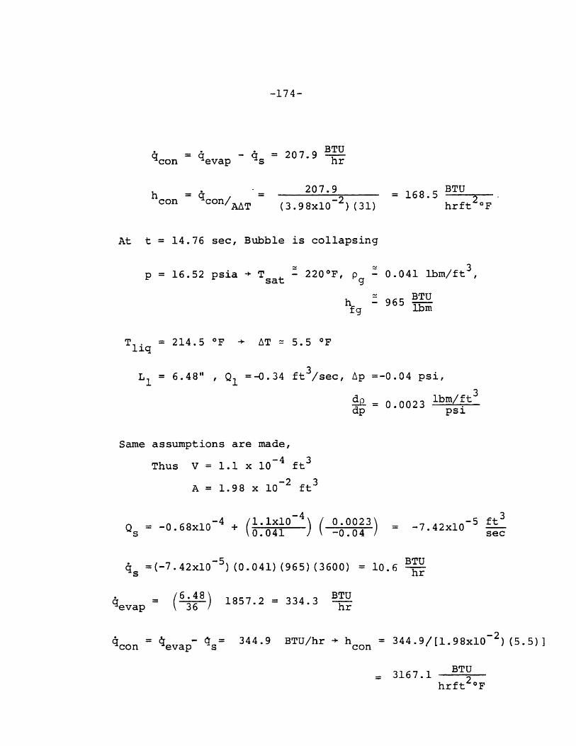
-174-
BTU- q = 207.9 BTU
s hr
h con con/ 207.9(3.98x -2)(31)
(3.98x10 ) (31)
BTU= 168.5 2
hrft2 OF
At t = 14.76 sec, Bubble is collapsing
~ ~ t3p = 16.52 psia -+ T - 220F, p - 0.041 ibm/ft ,
sat g
hffg= 9 BTU965
T li = 214.5 OF + AT = 5.5 OFliq
= 6.48" , Q =-0.34 ft3/sec, Ap =-0.04 psi,
d- = 0.0023 ibm/ft3
dp psi
Same assumptions are made,-4 3
Thus V = 1.1 x 10 ft
A = 1.98 x 10⁻² 3A =1.98 x 10 ft
-4Qs -0.68xl0 4 + 1 ( 0s 0.041 -0.04
-5 ft= -7.42xl05 ft 3
sec
-5 BTU4 =(-7.42x10 5 ) (0.041) (965)(3600) = 10.6 BTU
S(6.4836
1857.2 = 334.3
con = evap s = 344.9 BTU/hr hcon= 344.9/[1.98xi0-2 ) (5.5)]= 3 44.9/[1.98x10 ) (5.5)]
BTU- 3167.1
hrft 2OF
qcon = qevap
BTUhr

-175-
APPENDIX E
COMPUTER INPUT AND OUTPUT
E.1 Contents of the Appendix
This appendix contains a copy of the FLOSS com-
puter code, a sample input to the code, and a sample of
output from the code, as printed out by the computer.

-176-
E.2 The FLOSS Code

I cJ1i1%. s I JL~J 1.1. d1 .LJI)N VZ 3 A; U J.:.--I :. qj _ 1% 1 .1
duj %hAiii8h A111L SioiiL.m3 LI,A... lwih&d .inJ *i..uu, In1j, AuZCI. S1 !UV S1.. A U4. .dJ..1)..I. 'L
*s:.OA.Ls~~~i.....I Sl d.isa.. "C..3/.x...iWJ .aI i' A.Ia~.t -'
IjIJA~~s .~ * ~.j) )!s IiA a NI'(J... ..a.L. stll. 11lfI
06 4 0 # 0 0 0 * 64 4 0 94 0 0 0 06 4 0 AP 4 *9 41q 0of* 9
Ji 4b J'(j9)J...L C )a a ~ ..n ti.i "I) .. ' tC'9 2 " )
' ~ ~ ~ ~ ~ tl C,.,I..OAC'Ui..[ C.'e-.0':C .tI
*4644699494664#~69 49
a.
4.jLI±
At. ..LA
.4
*~~ 4 ... .. .. 4.. 3
w~J..... a..3. -C" LL.L '...... L ..A
1, .... ji.L .. 1.t l. j.. ai .I 1. 11j ...1UEIAi 'I
adoo9 .Aj**l Jil*4*. lI. 'Au l1&.Eu J i ~u.~A
0 W
C.F
'ii
to,~ L
rf.
'A

64:01J.-t 3-id -1 114'.
(SiO~~'L~cj4)09
0&.Ltui.I j I~j3JA4O.Nc.f 4 dt J l gd!,.lI'it 3i-L 1:J- a cLZd.,L. ndc. 4.~LOA 1lek cI..' a..a.i eI4Jiha 8 .M% isl~X~ i 3 O.
14,1414L Li(.3 "I42,a 61 , -l. 'II
((/i SI .L~~~LI. 1_j9 ' ji1 jAil 8,. L'd! a I I I d ; .hj. ! 1 'IV , I
00 rldl .aIi SI Z.i u.a e rs s Ti re~ I -,N
%au/'[ .i a..L b.i 3: i I :aZl Ifi iul Aiv Chi ttohIt .aua
!;nubl-l ~ ~ ~ ~ ~ ~ ~ ~ ~ : J')ZiiISAAal~i~ dl~ml hL fd. f
J... ~k ijj .a.j d Iai aLair 1) kf- 1V, 7 1.. 3 Ad3 .1Id L * i., jii~.as 3d. ddddfl Oki sh i)IU~o jHN0 4i.4,111f ... %, 31 1 'f
.a..1.. qiI uiLi& Z j) *J A .,fl J.4) .f!i i% d..Z) J Chh1 JIa) I 3 r',C
D .1) ('

f 210 C 1011T u~spt~r or tt-TPn -IF-TRVj1, X"j '-Lo2S.^ C CT V '? FT 'PW ! k7*V T1"F 1 =2 C TYCS I pW' unpprezrIIP Yr TI wr
63jC f: = 3 (rtVrS 7 I"N~ T".IrL RUBI E LFI'SVTI' TS T11*F2 le CIVFS 3 A'qD6 357 C IP'%T7Tf)1J4L piiIF.ly IFN'.iPS V3 TTF~,
f ,r V
1: T IT *'JPr1Uv FLI CI 'AmO FnIt 'ATIf PEN.TIS, "Awl
7.u nn' e Co.','f':
75 C(6)0 C66i" C -rr IP OUTPUT pv'r,:n. ')hJTrlT 'S VF1TTM 00;TO FJLF FO"~fOAePAT
V7.2.50"rr ~j
*Ij' 6ce C, i~!//V C'l~Q%',%~X "l'lXf3l
7r., .',T U.6,65 (') -:IrLL E'
715: ; TF'i V' ~ PT'"', V.flrS r' (T PAI), SIE W VTFP ,~
7'i,., i ,(/V 1 T ~ FF UP'POFYF TF
7250Lr
75'i.111 C TAT
77"' '"'
77: 't r
7k'~ C'1 V
7 .1~ r ~ ., .'T'A ""TCIA' o PAS N I I'0P W310 5lcPSP.02)Cj?~ 5(

s tSO3l~r P(' ) *STAPT
94 '!tEL '(C P
rof,; j* M '.D I
94 TTTvwr1..b'i'
111^ C A7 Tu15 wwv,", csvi 1-p :stliF ri T'TA Avr, P~I'A %-v II!r'rr vir?)-7zI cci. !:pr" c~fl Tujr rpE' Uivi n~T cuFI '11 T"?~ M~CFPr-r JOP
10 C3T' SILTfN
I . 3('
1.4r.uT':-L 'E Pirp ,.~IIL.O1 rif !! T- 12201r IrPTfrF
I C 71
I "7t ' f-L) TO 12-30
1100)..4.v
112'0 qov. plt% F--I(/1W7 Poot-MPDE PT SUIRl I FACPAW p'(,%,#I'11213 41 C' I0 11111 ',T4 .,
L 11r'1 T3TT1 k"~L?!' T"T *#V I IFP~'~ IS
ITn 41')0
115)z 1 ) '" 0.*

k )t t A& .LSL
);HJ.jt*i IJM .aiUlkl) A VUJ'IA fJN SAML~ !!ulj -3dU~ ~ Jj I. oil.~i~ I
tCP i C. ii- b.i .- i La CSOr
%E Jm.Z A&;LC!t
ILIIJd4.L.(Al .- 1L 4Mr
41 (10 I d CE .0 'L jL to t 6%Atfi~ hV .IIa hL a %/)AA -.I it CS13
h dt L-hI'S.La JIL O'I
ad JWj ' 2 Z 11 ' 'k' it r1. .' ~ uij12 *1-. ^ 14;,;1A ..,;e
clat ~ %-.L' 71j Aj* t':
)I ~pI i 0: 1.0 4,a)tJ. I ( (h A v 4 ff ,'L)*C .1. '.k

SAWVIIJV I14UROh 1.UZk,.qtUz '1..1t.L 3hW1J ..a'
JhlJ. 41911 d.sid 40hliOA dtd.~VA KI *ifl Lt. !:l ZtL
*JIJOji ;;1XVMA-ddAWGAI1i.~Di~ViDU2~)li.IIA Z
WI a) i (I CL.1(AI UNt M!
t d A I A A
&.a)At.iJAiA(Lb lAA
A.*' ilk: '2. J.'I1
i ImAu1JAAWhfaiAA
0000S uq jb u * u%.& 3
u! U*t,)Lhri* %)I
Wr~itrClit
r LLCU.LL
SLt'.'JLt
(LLLLLt(LLI
cc"CC!
( L
CLt.9L
cC .r#' t
' CL~t
f .;c I 1V(.ESI
No00

Its)"~ C J.TTW TUI CAL1!JlrTO' RD'SFI 01 TIIT PRtSqllRV f*FSrP, 11 THPr:~ r; Ol IS TVn LAQIF. 3UFS3 A lI O '"SOI(F Skrf?) I! TlIV E"P0Rn
V13 c IF -CE OLDT O'4r.
~P.~.TL~) I~ TO55
19. ~ ~ TI1 1. 00~
lalsU C VV*11.ATE "Ell YVLIFS "IF Te*" VAPIR VOLOF A'!0 RItRPLE LEPGT4
r 4; T~ -1I "j 6'. " L1(I)'.I r I It WF'R(l.I.) : T') 70
127c' 1 1", f) 4 00
TI(.T. (t.1) +I Ctf) l
rL(vV,:)2(*).Lj:*)*) -I)1 10
I*(.....w-~f.4rP'.Y1I.1) G') TO SS)Ci~I) rj 1 0 SO
2 4V 16G vr1)='II 7
2C6~u 1Ff 1t..S. II I' i'll C
20L; C Vo"iv ?fn ron-~ :'' rp -:;ry r~l.L IITIIT TSV I)q"D PrT4!q.VC,: TP- 1111I1 9911 L"J .. ''( L.I'Tq p,.-.*.vRT TH" 1 70 Aq'
7.-Q4,l c IPTI)7J dir';: TJ 'Vft'IA'Tl. vrf 'T4EY PFF nT7Y'Wr " ""ft. - 7 ; V'L'i'S Cf"3TT'll T- TT':3AU'.
21j.i G 1
7 11)0 . 1 1112 1 io 10) r L(l.0.( 1 T) 102212J9A, TIII121233 102 1r.L?.O..) n 3
2 1331 V% Tel 114

(ICCL ZL u. CL *.*.~)AI- rCrh0)
t :8 1 ) 1:r c rh
lVAU1S;- 'I ;11 (t" it
O~n.28 i
/(i~d~A*Ca)~AAILslJZ
1I~d A A +C~ )L, I)LFn.d
( ~ ~ ,J COi I(1) t ) A OL t ) j AAA)) V1 Ut. I .
01,) IAA itll *W i*( -1 GL It A A(v >'C A I.ti k")I C 7)
s'4 (.J Oft JL (1 Vi.G d1di dIlA aJl OsCckz
IIIr C.?. u1.1. -Li2F.
00~~~~~~~~ ~ ~ ~ l Zs I ,dIAA*(NtJVA: A0"

.L.Lbccr 00 Go,st& AHL.AJJu i ItM anJ.a.&U IbflsdkjL i.JulAu Jil LAUOf.jtdj 1S'ELtZ
*L.%a I. il OCELE
ObAJ~U~.Ih~a~.~pbl~akIua t ~ , U si CA& t;V LCr:"
heI t+.(lI .L ),;11.L A
iA.tJ .6tf.IbIk "al I hi i.L%4 RC1.' L ,U-O 1. J.I'J. L 1I
a4tot/h)k~ Atuijg 4d(.g M.L:., 0j1r
Ln Oft CI U)(6L-J'. (.StecJ
,;E U.Nk O-t c42
.k=I! 'd L --"
S~~~i VL L. (II.~ ')4 G tCt
Sit UL U (O~jnb6*0*Z'1.LVk,,41 r~Av!;d/.iJi IzJkh ,12
LtCC.9 O.. C!,Prsh"I ~ ..i. "
vgsi 1U, .I
d bd J. A A:.
lien ~ ~ ~ ~ ft c4U~ onL I @It~.. ,.nJ itG.~~e.u.I rf~
).Jj ~

Ou' 3.1. 0.i
Att CcI O^E
III. L yL
-(1 ~ ~ ~ ~ ~ IIA1 V3.3 1k0 )1id ((dI- C!Wi..ia isu/(( ti "C).I- 0 9 Cc ; EJ
t t-Vt*'lWLL .LA Ca. (t. (CL 1.a.L& .. i)C.. 1O Ji~vOtI~ .jkM(,(Aj
Ott u ~ ~ ~ ~ & (al ((-J~LhnC ML.)sJ(.I),... Lf
.OJ.LE Eai taM %.u;i.Z~ajL. ifAliSId~~~~
Uiic. WO .aj~ 143-0 luibI mi) iiJ 3d I3. (i ), * a 1:)rt.t.L L i .is
z.'m t C -1 05ISL
4;1 t +1 U U t z,

3(711) '!n T' 14
3051 ~ ~ r~n 1roI
167%* Ce', (r I. ' I N v . M "1- PN- T
I1I szp 151 i (! (L.' I PLT
(1 9 At R1, (" I I TCrfll.)*puLJQ'L1.*rpf
3110 % IL )-T I)))/ UE TT . -( qr4 2(N-1 ).rT r f))'Ivf )
3 1 ., I&(ETF.(L(tf)(1I! t)PLTM1)
31';:" 15 0 T 14
1-4):~ T') 109
331.. CS I(.rTq~n !)C "1
31'o C oTrTCprt3tg Tn 152Y~cYI~CranI
3175' ID':!)CfUPWT~t31f,5 * E TiD i'l335," If-C J 0J,- *'IT A~~3352 19 C 1

*1it ( nei'(fJ i1.aCL)h' ' lI)Li'( )013 ('Z)I aI')It c W
(01-1 ):.#!bA' (L10 .ZOSI
cq),"k1( i )Lli ( 0"MI %az I- v
(,#O ItJi ))f zI.fI(O Fo ,1 nI ft) ACl I
0j J t 0 AA LA A* I d.1A tZ) A ' U j IA C) 7 -Z'El.4 L-o 160 u t*1 u' 31" tI AA (" J 31
U *A R C IS 1 1 -1 s.AIL, I a,*
'aIr IAk Q
~i~hJd.4 .~gE'A!QE
UL ~ ~ ~ ~ ~ 0% uc u (Lh)6A1L1C4)uAA4
I--- s ., 1
Cos, Oj I-ii&1a.3 I~J.3h~J ZUIA J..iidi3 i t d1f~fl dL
Sd.L~~~~~~~~~~~~~~l t~UUA~V~aA.1 iI 4 Vi)i& ~wiSuS
dli)~~~~~ .. tu )JaV~tA tha Ii % A A t ( (J.j i 1 E(In'Afl *. ia(113#6S t h i f- S1103 Si dlA-(hL VbV ) +( t t .34 ( W iu4 1, ~
9 hi*(t .o &--Xs: &lA ) ((-l) U4ASIS, (I -. i 4 t I S m )LhtV V 3 '.:T14A..,u ~ ~ ~ Z "~L~ .JwA~.L 41 a., wJ 1.3ij.~.~dd U L U4 ViO J. tA.a&J1 S:If~) E.~.
co 0 0J.u!) W U'i.Le.lL4;)J' csle3co~~. UZ ., U) ~sN
*4la. ia( u 1j.,L llOqJ.)IAk PI'A L,42(3atl JAIt :I jhC17
* (u~JzC~WiI'uut)~sAOASi 'JZhtUdI.AA Noid'UJfa~h11a .d.:AJ llOdl;3idp 1
I.Su UJIV31 -Jt~b il '1 Q-l C *'

OaS.1idSdj -.61
i&4.A1 si S4JdM mulu 1.,Iufg tstaJ t) E~V'QA.A
04,414Ma .iskolftib V OAi.s&,b *4iE'h ia:j. 51 i111M~~a~SSi 'aal 3-iji~AOt~j ..I '211d KftA 3.:.! ;U tfiLIVUt.1J. a0.J Li$
3&LLj.djfts 111 (1341 de11a.J~J h.l 86. s~s.IM) St.LV% Di2t .i",i1001 S1 'Le
I ~ ~ ~ ~ . Il .L 4 ./ ..^;
1.1' ~ ~ ~ ~ C (cV.;11rnt S4
(~33IAA(uOSL ^.Ltd* I( t,%WLghAC(W"A)4 G~v~O
1.UoL b0J C3si
-21 A t 4.1 3-' .:;IA i ; .Wa Oj
~~~~a] L.L LZC2A S)iZQv E L 18 2 ~LiE
00~~~~~ Jf:I %,. ,L(;1.ij(.. N hi.2iJJf i.L.0J *0@ AOIMwbOd0 SI IA3 GiOliS JCJ.11-i-MA 0.94c
.u~.~mU.L1,..d~.. hS w14 11Lu d.aU OM.~.eI~d4.'? £"La OS 2 (6LE
Si~i~...J~~.) D..id ~I4 AU II.4 .J.L is! A.L! ~ 'fi.I.J (~IdI. h.!. 2 ?LtL
~JVU32 iV~iJI!~dk3UM ~u .M .IJJJ ~UI UU-.J& 0L14 -tLL~a, I 2~ E
*~ ~ ~ ~ ~ ~ ~ ~ ~~~~~o 1 . ,iE4.gJ~~JiaA~lLLUt~~~L~ f.1d atn :'-'*n,1u~ (I~a.4 d''. A~A X,-u/l~a4 U3'L- ..j .3= 0,i ) .~ 2Jl LSLE
*'UuW LIJJ L..jJ AMA1tL4 A~Ldfld2 3ISt. 1JUQW .jh.. ,bi..I 3ISI4.11 %
d3A,.13 ARV0.1 M AiJ.l .Loa H(~~ :601,J ASLU 611.AlV l2e 11 2L h lfl .'i .1S 21 .iEdjIA ill .-jLjAuU3Qa:bvJ j 4i imAbi Nj l iL iO. 2 ZC..
J .Vlj;Ivj 1 Ald.1.30wj -zl)N NJil I n 0 71&2~f'3~(L~'?II~d2(QC)1VAJd1JW. k.C CLA
J'Jj-sllo O 3341d1H1%I S C~st Jd SII Ih1 3fZ:Jrc C.

Mkllla m' ;D Q 9 ZyE /..j.
h' Moecl'( " .* nl *l " r(c.Z e 4
0 &dd Otez M~v 1(4:)4vc:j, Iot 1) 1 d, (t' * t 4Szf
-1'( o,( J IL I ; -%4
(4-6 L,;l10* Lectr6tCA !I
LIz W. J.
00 -.- L. !
sil CIL O4) ( 000(MiSeaLJ-1;'1 )11 sh z I
if~~ L1 Ii~ (J dOEJ.
SEU utoclo(X S093 Li0 ue ("l SA1A-)A 031Lr9
d it ' ! 1
Ci; 611 .1
IS 0.. .. (O001"Lf '.FhI :.L
*0-CSL64

23~ *1~
'4411
4 3 15 .
4355.1
'375f
441
4a' 4 1.;C
I.44 0
4;6. '
is'4's S D
445~i
I452'0
ua 4
a!) 5 :E
"b7)0457S0
c 7HTS RI')UI0 CAP'1IiPFc FFTcT'~v* A!ft TtIE0 ?'wt'S rD"I TRDII? Tfl eP"n11I'T4Fc IIYPR. T117 INPUT7 . rIVqTRTIT1*. T~r CC1Pr1 rI VVIF PY T1 ?RPc vA.T4 PRIGuPv. rn RME4~, T11F LITVU AVL, DTA"E1' or rrI f"jwfprpm
r T, A A' Cno%7o or rrbpvfrYi~p ' "IF TFP FT , TV 7r0fgTY'j,1f?C L/'!. V:Ii Ail An1f!'1"'L PrfIlTilrf T14 rp-rr"'nT (Vrf'%
,)pl1FjrFs, 7I.I1vr) p!p*p FT'.)I! PrP"rNv'Pr RT '*'I rrP An'rj.c ALSY) 14e FQI'VAI'!T W.D'!S. T11E Cni"IffrIT 4I,"PFpT14 ST!'VC 'UVS OF FOLL'n.rD A"' FVPLAINED TV TI'F 1IFSTS 14 MPE" F3"~ 71W
c RYT UL CC'DF, PUT P7VTATfl PR~v TI' RIW1- WILL Cw11"r FWR riti1 PrULTS,Cc
Dc, lf) Tvio?
"0 1('O' ff-.,JT
11)l TP d
J.?r I -I
LL=Y K+7
3 A='tL- 1

ra=%C'p(2) (~'
(451rl. Co s - 4rv
Sc
f. 3 5. r
1a7F C- 'F crl ! Inv ' V 0 ii TV?. 'FT OWN R"" u'fl' l~l 0 Y u:.73 ) --)(a~A (R.A(f ) Aft' 0IF' 1 -7 41.ATtI ?!-I T7ir) 89 1 1
476rwO IfI.'1 .) ,~ Tid P I.0 ,!S ~ "n)rSirr,4r-
#A71~c c~O !Ti4715 t ~ G 'c TH- .PlTMLrf prli r-o n fr7
to~~ ~ 7j-) : C.~ A li tP MET ?fl03jO 10FE
474;3 c COP~l. Tn ,Fe tCL LATW
4745r, ~ C r lvrtq rw ^r'l VI~ YT
475:: cAl% ?bP~OI PP*#P

'it ~ 4, L! OLcSr
VeIOUtdVIN ',wL-W( LOWiCL ottt Vfl- I*t *jJvtJlq'LEL' ))z iA.s SL
(C1 In-'f)6).S04%'lu)/C3* L t+j.j%(" M IA tL3L
GO'Um 01
m 1 L.l O. CS9.&.r~d-.WION 0 L -i.- i
'(S~lld ILO.) "%.LSB. .L1Svl.'# 01 I'(ai' iilfi~i 'AR r"Au
(dihil).1,1.1 I4IZIdS'(41h.#Jt) IJ.ISC,OSIA .-in 'LJ.I Id-.LVP~)
&AJ .,jAl.. jiV S UHJ. *(tail) nIfgu0S 41AC11 dC a sl-~
'.Lt' (0L'e 4 so.'f0t 'c: I I ' ( 4 ' ' lI *!)X.1 3
#.,:o 4.-.Lat JJ4 .. t .6 1 0.,'(U1 ) -- -1 A J'Iw ) 1 A % b mOZ

C. t
P. sf 'S
(>.TS
( ( *( **&Cbt.
(Vd /)IL tUv CS re-,UE S
*' I ~CI~I CO r~s
ttzu(J.adtx S 'C 0 L
Go=jtef$, .1 )= c~rt
L S E
SE~'c 0. O lZ.~d)A

'.V'vJ/PLIT'7/r~oT ?,TTTr ,XPCI 1'
TH13 kOOT~bF Vqv.S Tl'? tTRRARY Sflm PnllTI'Ir PT(r1R (IN ?HP HITllPqT C~~f7 &CffTjjY VAX CnOIT'.P T" *'SVPFmNT
I :A~LZ -PATTF'ET 'TUA? tt'rS kDPAYq SF'? !J PT T"E tIS!RP10) CNFATES T'.r nL.I19.
:55Zcc ~-
(i.,3
c 7.
5'I J5 -.
C), r
5i95
FROM 'TPANSTtNT CALCULATIOW
Ln-
Il
T'vIJT VIE TTTLFS IF" THE .Pl.nTS. ?14FSE PRE "PRE LASTFOUIR DlATA LINT.r T"E TITnY FOP TOF V-AXTI IF TPE VLflT
TRFAIR*4 C1.A'fr,0)
PZT" ?4?, rIIoVF's U';TS-1 RESUJLTS'q0 100 YslRD3 1,1u ~,~rF(T.".9*2) q-) T11
Glo rl 100IC If[.j!.1) 11) T1 7'n
aro I*~u
il) rf% 110
30 T-).~5)C 1 ~in !Iiv
a.TF(r.lve4) In TO %0
60, AfTF(;..) 50) 1) At,
G n TI I f 070 ~ rI~.V' .0 TO eO
frll37!(T.1)3*.C(J T! I'la
'aC C!v VP( T '1ui'"
TrfvtPi?.roI.7) if) P,) 1030
10 -o 21

5 1 O 0 r GnrS JR TIM! VT'RS? MITY Cotllqr Or~ TIM~ LITT IM? "t-
C ~ ~ P r-SV 6 ;AL '?VIXW Ti !FT !TEl'if nl.T Vi'I?. 7RtPC ~~~ ~~ PE''J P.C~ D 14 Til! F'l"TY O'UST F ?P"f 1'
5r132 PLOTS PR0O?7LW.
SP35r. 200) VfJrAT(IO42)
5184J050) GoV. "~t nsl .,oov~!r PAT~ 4n"IT" "?
*)4rpi 103CJT i0 'III:2" CAL!.O'I?),S AVTI''L
C c Vol so(.% F
54t~~~sf 3000 ;" ,9)0
s r t: ,. ' 'I
Es D1~'

-197-
E.3 Sample Input to FLOSS

SIMULAXION F TEST 9 CONDITIONS; LARGE 4T CEFe.0.050 11.000
175.00000&00U.00CO05 2 3.0.013 9.0.1667 t.00(& 0.0.L83 I8.0
,-83 co9.013 0.0.1167 '.0.3V5 .0000495 09
1052r0o3Ue4 0
SCo6 i- 09130
1200
15001400v900
1706IPOD
19002.0021, c
23C 024002600C26u00
29003DOC
14225.0
140.914L,014"10014 Cl, 0140.01L.C14A.014r.0I 40.0
7?.0
3?2.200.390
4.00
1.0010.0140
4.0
.0051.05
14.70000 17.20000C004900 48800000
0.0C00D.
250.00.0.000*D75 75o
75 75
TIPF (SEC)TIwr MSC)TiME srC)71"r (EfC)
l.pp0000 07000.110002000.00000
1 3001 4
VOL. FLOU R4TF (FT**3/SEC X 14**4)PRFSSURE IPSIA)
fUiBLE LE>H flINCHES)PUBBLE LCthiH (INCHES)
.1(0*48.48
.48
.401
.48
0.040
H
C0"
I
-----~L-~ ---- -------------- --
-199-
E.4 FLOSS Output

S IULA I ON OF lifST 0 C('P I I IONS:t LARrG HT COE F.DT=0 . jO KHT~1 Ck.Tr0-feon0. 0 POIFR= O.3C KW~ PSTART=17.20
1I41TIAL TLMPEPATUOIF PROFILE6 225000p 140.000 t0* 140000 140000 140.000n 1400001400..0 14 0.0I0
NODAL ARRANG(MPrJTW FT/NODE 0.100 0.480 0.480 0.480 0.480 c 048 r 0.480G*460j 0.640
T1IME 01 np012 03 OTOT P Al8L1I BL? RL VVAPI VVAP2 VVAP A82
c .o 0 0 . Vo F * 0 0.000.NIC 0.D006.00 0.Ooor.00 17.200 o.occl~coG.LVfE .)0 ~C r 0 G0001.06 0. A00E0 0.o00r+00 0.000E.C0 C.C006.00
a & O 0 0015 E162b 0.163E-05 00314[-05 -G.103E-06 00304E-05 I l664 6 0.15rs-1 3b 12 JrF3 3 b97 7 4L 0 3 0.1506-02 0.7571-07 o.81SE-07 C*Ir 7EL06 0610517-C3
ai1~ a,5'99r-tb 0.643E-05l 0.1241-CA 01199E-07 00l?4r-c$ 16.669 0.10!50-03003511-02 o.384r-u? 0s7,lo-V2 0 *315E-r6 0.4036-06 Po770F-06 0.1051-03
0100.179E-04 0. 197E-04 0.3700-04 0.166E-06 0.372F-C4 16.728 0.105(-C3 CD2.121t-Ul 0.13CE-0) 0.2500 -01 0.12?E-15 0913617-05 0.2f3[-05 06105F-03
0*2.A 0.3squ-U4 00412E-04 0079f6r-04 0.469E-O06 00POCE-0* 1(6.794 G.1(SF-C30.303f-01 0.326L11 0.6291-0) 0.311"6-05 09342[-05 6.6cll-05 0.105I:-03
o..*50 0705E-U* 0.7561f-04 Do)46L-03 DeM26-05 061471-V3 16.879 001C51-"3ce6354E-01 0s6FCF-A1 0,13?r'00 o.6&ir-r)s 0.72CE-05 09139E-04 C01051-03
r.2 7b -002086-C3 -0.724E-03 -0.433F-03 -0*46tC-04 -0047q[-0 3 12.094 0.1c56-030.143E-01 Go V It-('I 0@295F-01 c.5isr-os 0.3'59E-05 0.3100-05 0.105E-03
fuOA.21 -0018917-03 -092W4-03 -0.393r-03 0.311E-04 -0.3c26-c.A 17.707 0.1CSfC3093OMF-02 0.3e006-P2 0.0CO-02 0.324E-06 0*31!r-06 0.639E-Cf6 0.1050-03
NO COhV6IR6f8CE AT THIS TIME0 STEP T= C.281
RrSTAH1
C.2t-l 0.?39E-CO; -00239E-06 0.1?6f-19 D.424E-35 0.1361-19 17.107 0.0006400J).1P)L-34 2.1?lr-34 oo3sor-34 o.eoor~oo 0.000E.oo o.3o9f-38 0.1056-03
0.331 0.0001*oo 0.C006.00 C.Over#83 0.0006.00 0.0006,00 17.200 0 . v00 f0G.M4*03o o.0tooo*vo 00co0r.LO 0.0006.00 coaor*00 o.0rar*oo 0.0006.00
i.ii 0.009E*00 0.0006,flo o.oocr~oo 0.0006.00 0.t-0E06.0 11.200 0.090E.00

a & 3 0 1 * 0 3 rcrcnEc *O~OoorCO o*OODE*OO OOO'oa0 o.OOOE*Oo
0.121r-c3 00774r-15 0.15cr-0a 0.757[-r7 008131-07 3*157E-06 00105E-03
00 e59SE- C5 0.643E-05 0*124E-64 0*199[-07 0#124r-o4 L6. 664 .0(C0 0 M t -02 o0 .F4 r -c2 0*741F-02 0*375E-06 Ce403E-O6 oo7we-o6 091051-a~3
0,531 G 91 79E - V4 0 o192E- 04 0937or-04 0*166E-06 0. 372l?-04 16. 728 Oo05t S-C30.I21[-01 fl1C-I0.2501-01 fl.127E-05 0*136E-05 0.2637-05 D.105E-03
0051 09384E-04 0.*4 12E-04 0.796E-04 C.469E-06 OoRCIE-04 16.794 0*105r-0300.35 -01 o.?6 ~ .qr-oi 0.319E-CS 0.342E-05 0061)E-05 D.1057-03
J.3 .05-d .76-40.146F-03 09)26E-05 0 *14 ?E-01 18 6.19 0.IOBL-f30.617.4-01 C*661'(-r1 0.00 0.67 If- 05 0*7201:-ob 0.1391-04 0.105f-03
0 6b -0.169E-V 24-3 -tP.39?F-03 -0.51.87-04 -0.0 4'PE- 03 12.407 0 1 C51 -C3
i 7 -0*196.f- -3 -0.2"12E-03 -0.q06E-03 0.GGCE+0e -0* 4 F87- 03 12.40? 0.105U-030.1 7r-G I C,. 18br.- 1 0.3607-cl 0. 164r- a5 0.195F-05 003787-05 0.305E-03
NO0 COtNVEPSENCr AT THIS 1 11#1 STEP TZ 09657
0.LC.7 00339F-66~ -U*339r-o06 0.136[-19 0.640E-35 0. 136E-lq 12.407 O.0DOEOC~C .2f 2E-34 3o277C-34 0.s3qr-34 0 000r*f0 0.0007.00 O.5w-67-3f 0.105(-03
00 7 c O.OOO.,v o.aOOroo 0.000h*oo o.oOOCE*o 0.O007.00 17.200 O.vOOr*0c0 - 0L E +00 1.01,017 0.000U+00 0.0007400 0.000 0.0kc7.00 0.0007.00
a.7 111 O.OOO7.zc 0 .00L 00.0 0.0007.0000O+O 9OnEO 0.OC07.00 1720 C .rcOrO30El 0.0007.00 0.P007.00 0.P007.00 0.000E.00 O.OGOL~uo 0.0007.00
6c7 C*151E-f! 0. 1637-Os 063147-05 -0.103E-06 0..i047-065 160.4f 00105[-030.721E-03 C.714E-03 0*1507-02 0.7577-07 868137-07 0 .157 -0o6 0.*1 05 -0 3
500.12!9[ r 04 -sCl4E-04 0.199E-07 001?47-Di b 69 D.1757-C30.357E-02 1 03841-r,2 0.7417-0? 0*37bE-06 9 .4 03E-06 0.7787-06 60105F-03
U 9 L7 co1197-P4 Go.192[-C& 0937PE-34 0.16CE-06 0.3 727-04 16.726 09105L-03D.121r-Ol 6.l3ncf-o1 0.2507-01 0.127-05 0*136[-0i 6.263E-05 0.10 .S-03
0 7 0*384E-o4 0.4127-04 0.7961-04 0.470E-06 00801(-04 1 k 0794 0,105E-03

Oo363E-01 0l.326L-C I cof 2 qc-oj 0 9319E-05 0.34PE-03 0.6d(,I-05 0O9105E-03
19007 .0(~ 00156F-04 0.046F-03 0.127C-05 0.*117-Z3 169$79 CoIC!F-G3G.Lo3 '-01 0.68#-01P 0015P1'oo 0.671E-05 0.720E-05 0.15R91-3* 0*105(7-03
1.032 -0.156(7-C3 -0*i6"F-03 -0.325E-03 -t.6311-0* -0*308I.-cl 12.93! pe1c5c-C30,.267E-01 0o 2P41 -uL I D C1'5 1 -01 0.280(7-05 0.298(7-05 9.5791-05 0.1051-03
19035 -0.205-C3 -9.221(7-03 -0.427F-03 0.117E7-04 -0*15E-04 13.275 0.1151-03
NlO CONVERGENCE1 AT THIS TIME. STEP Y= 1.038
'!ESTA3T
1.038 0 .236E -Pf -0s23CE-06 -09305E-V9 fI,526E-35 -0. 3051-19 13.275 0.0co01.000.216E-34 C.2281-3* 004*51-34 o00oooro 0 0 a a o 0.4f7(7-50 0.a1 05E-03
1.088 0-40G00 0o o. DcGEt*0 0.opoFor 0.000(7.00 0.0001400 110200 c~oar~01.00.0011.000 o0ooo1.o 0.o00F+00 o*0001.o 0.0001.00 Q.0c0E.00 a .000.t a f*1Z j
1 .138 0. 0001.11C 0.flOO(7DO op 0o f 0o DoaCCE4o c.J0Dr~voo 1792CO C.flOO(.000.01*0 0.o0 0F *ro D.C001.00 0.0001.00 000001+00 0.OCrF.1 0.000E+00
Osb .151F-U! 0.1631-05 0.31*1-05 -09103E7-06 00304r-05 11.e646 0.105L-033.7211-03 1.774F-J3 09150f-02 0.757(7-07 09813E-07 0.1t11-ffi 0.IO05F-03
1.23b a .599r- (! 00C*3F-as 0.124U7-04 0.199E7-07 0.12*14-aq 1 6e.669 0.115(7-030.35
1E-02 Goib*1-02 0.7411-0? 0037141-n6 C.4P3(-06 0.1787-06 0.105(7-03
128 0*179E-C4 001921-04 0.370(7-04 0.166(7-06 0o3 72F-U04 16.728 0.1(751-030.121E-01 0.1301-t-I 00pbOf-01 0.127(7-P5 0.13CE-OS 0.263E-05 0.1 05E -03
1.338 00384[-04 0.412E-C4 0.*79 6 F-00 0.4701-06 0.011l-0* 16.75is 0.10bl-030.3031:-a1 0.326r-61 0.629C-01 09319E7-05 0.3*2(7-05 0.*6( If- 05 c.10S(-03
1 o3f-8 09705E14 0.756(7-0* 0.1*61-03 G.1271-OS Go.147C-03 16,0979 0.105L-030 .6.5'1-31 0.o8a6r-ci 0.133100 0.672U-05 0.72DE-05 al.19(-04 0.105(7-03
1.438 0.5461-04 0.5811-0* 0.113(7-03 -0.9912E7-05 0.10*1-03 1f..*86 0.1051-030Aq0 0.9f 2r-c0 0.186E*00 0.9*44f-05 0.101(7-0* 0196[ -0* 0.165(7-03
1.463 -0.3581-( 1 -00332E-03 -0.6*01-03, -00699E7-04 -0.1101-03 10.753 0.105L-030.1611-Cl 0*171E-31 0.3381-01 0.115E-05 oeIaOE-os 0.35...-05 0.105(-03
f.0 CONERGE7NCE AT TtfIS TIMt. STEP Tz 1.463

PST ART
.43 00789(-f6 -0.1119E-06 0.1771-17 0.652E-35 0.9177L-27 10*7i3 coocorco0.25iE-34 C'.21.5r-14 O.'1?2V-34 0.00G40O O.DO(P(400 C.'54B(-38 00i0sr-0os 1
1.513 0.L00F.'0 a.oonr~oo 0.0001.406 U.occE.00 0.DO0(.bO 17.2GG 0. 0 3)t*no0 Cc aU*O0 a.0cot4(r0 0.Ooor40o 0.00orcoc 0000100~o 0.olor-o 0*000E*O!
I .5t,3 0.000F.Co 0.0oOF*0 0.000C#90 0*000t*0O o.ODCE.oo 17.200 0.0n0C.('oo.GCLjf#00 O.oCoi(uo o.00Ot4oo o.ooor~po 0.000c+06 O.ocol*0o o.ooor~on
1.613 0 e151 E0'i 6.163E-05 0.31qF-ob -0*103E-06 o.3cq[-es 16.(A46 0.105E-C30.7211-.! ~ 3074Et-03 Oel5CF-02 GoM5E-07 0.8131-G7 0.157E-f 6 .0.1051-03
093t, IE-02 3&4FC .741 C-02 C*375E-1lK 0.4031-08 PT781-06 V .105E-03
1.71.1 09179F-L4 00192E-04 09370E-04 0.16fif-06 0.3172E-C-1 16.72* 0.1051-V30*121E-01 00130r-O1 0.250f-01 0 & 127C-05 09136E-05 0&2f 3F-05 0*105E-03
C.)
1.1(3 0*384[-ft4 q.4121 -04 49796U-04 0*470E-Cfi 0.VC1E-04 16.o794 C 9 0 5 E- 030.304[-G1 0#32?E.--C 0.6,29r-01 0.3191r-05 0.3421-05 C.6i~1(-c5 0.195E-03
1.8 p13 0.70SE-CA 09797F-04 P.146E-03 C.127E-05 0.I47E-C-3 16.1479 0.105r-D30*63'iE-01 0.61461-v1 0.133 000 0.672E-05 OP72CE-os Ge139E-04 0.1051-05
198'5 0.90b1-L4 0*971C-04 0.88F-03 0.2811-0% 0.190E-G3 16.951 09105C-03D*5N-1 Dv1U;l 0.1771#00 0.89SE15 0.963E-05 3.11461-14 001'55E-03
I1RL,3 -0.2091-C3 -0#226r-o3 -00435r-03 -Pe120E-03 -0.5511E-03 1177# 0.105E-05093t. /F-31 C.375IE-1-1 0.03&E-01 0.375E-05 0*3981-05 007,431-C5 00105E-03
1.870 -0.273T-fl -0.295E-03 -065168r-03 00209E-04 -0.547E-03 32,193 0.105r-o3a 019ar-31 v.?fl'-it 0.3971-01 0*201-05 O.213E-05 a0off181-0r5 0.11.5-03
h.O COKVER61t.CE AT TlilS TIME STEP 7: 1.870
PE! A 14T
1*7 .47-f -3.4411-06i 0.285E-18 0.000E*00 0.285E-18 12.193 0.0101.000 O14 ,[-34 Oelb2l'-34 0*297F-34 0.0001.00 0.0001400 0.31 "E-38 001051-03
1.920 G00C01 0C .0001400 0.C000 0 iOOOC.*00 0.0101400 17.200 .0101.10E'9eaf~f .0001.10 0.0001.00 3.000E*60 O*ooor~oo 0.00E#40 o.ooor.oo

10970 G.000f:.UC O.ooor*oo o.oocr~oo 0*oooc+oo 0.000.*00 179200 690801400O..oo+0 C.0ofo#00 O.Coou~oo c.000r~oc a.oacEO0 0.oCOr*0o .o.oo0op~e
291)20 0*151E-0c, 0.1631-05 09314F-05 -C*103E-06 0.5041-G5 160646 09105L-C309721E7-03 0077417-c3 G.150F-0? 0.075717-07 0.81317-07 0.1r-7r-&j6 C,. 105E7-03
20clo 0.59s17-i-! 0.643F-65 0012417-0i Cs199E7-07 Do 1?4E-01 160(69 0.1(5[C-130.311I-02 0*36417-1, 0074IC-02 t,.375E7-06 0.40317-Of 0077817-06 D0%.C(-0S
2.120 0,179E7-04 DO.19217-04 0.370r-04 Do 16#7-06 0.31217-0* 16.728 0.10517-030.121E7-31 DOI1'If-Al 0.2501-01 0.12717-65 0*13617-05 0.2C31.-05 0. 105L-03
2. 1 7C 0.3841-04 00412E7-04 0.79fir-4 6 94 7 E- Of.8011i-04 1(.194 DoltC-030 .30'.C-01 .32161 -b 1 0.e129E -0 1 0.319E7-05 0.34217-05 0.6( 1 E-(5 0.265L-93
2." Co 00.1067-('4 0.75717-04 09146E7-03 09127E7-05 0.14SU-03 16.8e79 0.1 (517-030063'17r-c1 0.68E81-P1 0.13317.00 ('.67217-05 09721E7-05 00139[7-04 0.105t-03
2.270 0.551E-'4 0.siflbE-04 0.114F7-03 -Coqlo17-05 Go 10"1-03 16.490 09105[7-C3O.9U117-GI 0.6Ff .81.00.94717-P05 0.01IE-04 0.lcif1-04 0*105L-P!
0:
2.25 5 -0.2717-17 -0@296E7-03 -0.57017-03 -0*08117-04 -Do587-03 11.287 oe1D517-9S0 *2479 I 3.27(L-,ll 0*50917-01 0.26?17-05 0.27517-05, 0.5?5f-CS 0.10517-03
203171 -09294E7-03 -0.31717-03 -0.61117-03 0.59817-04 -0.'cS117-C3 159C23 0.10517-030.7,117-02 C.711L-1'2 C.146r-Qz 09777U-06 0.75117-06 0.l;,1M-C5 86165U7-93
NO CONVERPGECE At THIS TIME STEP 7: 29301
IST ART
2.3E1 0.49017-06 -09490E-06 -0*149F-18 0.56517-35 -0.149f7-18 15.023 O.OJOotrooe23f.E-14 0oplif -316 0.4f7F-34 0.00017.10 0.0001*00 0.49117-38 0.017-03
2o.351 Uo00017. C.pooU*op 0.0001+.00 0.00017.00 0.0001.00 37.200 0.011017.00.001+700 0.bcr017.e0 o. oor *00 0.0007*P0 06000F#*00 0.0001.00 0.000[.00
2.-4 A 1.01~ 0 o.nonr~oo 0 .000! .00 0*000ooo o.cobi*00 1 7.200 0 .0 090 .00 OCIF# QG 0.3opofm o(0.coot o0 c.000.10c 0.0001.01 0.000E.00 0.00017*0c
2.451 0.151E7-of 0.16317-05 0.31417-05 -0.10317-D6 0*3047-15 16ob46i 001GS[-030.72117-0S C*77417-03 0.15017-02 0.757E-07 0.81317-07 O.1'717-06 0.10517-OS
2s501 0*59917-05 0.64317-05 0*12417-04 0*19917-07 0.12417-04 16.069 0.10517-CSCo35 IE-02 3.3d4F-02 0.7411-02 0.3?SE17-16 0.4G317-0f 0.77817-06 0010517-03

to-3901*0 sa-if9zoo so-lictoo so-Ualle to-10WOO 13-ca-lot*o VZ1091 00-ULTOO 40-3149100 *C-3OLV*O to-ja6loo t0-36WI OIGOZ
f9_lfsoT*O 91-MVC 9jJCGk*Q 93-JqWo to-AtWo ev-14WO ZO-31qf*olo-A3too 694*11 bo-lvetoo LO-3661*0 *9-J*Zt*O 93-ick9oo S:-166;00 0 6*z
CO-IGOTOO 93-)Lit*O LO-litsoo LJ-]LGL*O zo-jo.100 To-ItWo;3-]Slt*O 91pJ691 GO-Pollcoo 90-3VOI*D- Go-DOWO qOjT9f*o Uq*z!
00#100000 Ojoilacoo 000300000 03*320000 000JO0060 0303OW3 00+300000OOVI 1 00#100000 00#300000 00*300000 00+300000 110100000 0!90?
00#300000 Oo#j33OoO 00+3000*0 O34JOOOeO 00#JU30*0 ql'#luQOoo r**l.,9clO00#100000 OWL t 00#300000 00*3003,C 00#30WO COOIOJJOO 03+300003 OIL*?
C043900*0 OJ*300010 kc-islooo t;-)Llzlj tv-14tizoc03#303000 ILGOLI OZ-39L9*0 GE-1990*0 OZ-JV19,0 9U-3qZt*O- 3)-30ttoo OUoz
INVIS3H
Moe 21 d3LS JW[l S1,41. IV JJfjl9SJAN0J Ofl
to-IGOT*0 !;a-jctt*o 90-30WO 90-304CLOO 10-39WO eJ-14L9*3 zo-lqu9*0TO-IG31*0 11GOLl to-le9koo- %PC-3fi9q*O vO-j9tl9'G- CO-36947*0- ia_3cqa*O_ OZL*e
M
C)
CN fo-jGotoo cjo-3L9b*O .0-3GVZOO GO-3ozzoo 10-39WO t0-JLZZ&U IC-3LTZ'Cr9_3Gjl*O T69ozi tO-369;*O- bo-319a*o fO-JLGPO- ic-36we'a- co-389zoo- fltLoz
cc-IGatoo so-3GIS44 ioi.3fitvoo 90-39WO 10-19LL*C U-16firon 10 -3 9 1 c * aca-11;0 1 *0 VGC 04e t cG_3;L4 *O_ O-Uvz*o- 1:0-39%,44 a- io-jeceeb- I ZO a- L- L Z
TO-lGotoo *a-36itle -o-3V9GOO io-:locio ua#j1poloo tG- llfcjoaL%9*?t to-36*v*O- Cc-3bTTo- io-iilsoo- cc-jk9f*O- il-itsi-c- IoLoz
co-IGoto *O-joqtoo r9-3kL6*O Csd-300(3,0 oo*j6LI*o to-joefiou 10-1499*0vjlcs loc Itaelt Tq-3t9d*O CAO-JV99*0 CO-396too U-310too 100-3910660 91911Z
;0-390100 qo-31ZLOO GO-UI9*0 OO#jCTT8C 13- 1949*u 10-jift9logo-jal 1*0 61909t T3_j9kt 00 soUcloo CO-39WO *O-JLSL*O tp 190L 0 a tq9*e
TO-JGOl'o G4-jt.)gob so-letslo t;u-jfitclo to-JUE9*0 14-49clito lo-oaf*aiu-Isat-O 4;6L 09 1 *aj1jFj6O 90-3tWo #10-196LOO *a-jai 10*0 ku-iWoo Tn9*Z
io-jejoloo sojv9?oO GO-i3itoo G3-ILZt*o TO-JOWO t%-VTt*o T:_lletoccc-isoloo get Olt fP0-3ZLC*O 90-199too O-JCLT'G ve-IZ6106 lo )-36L t *0 t S ri 0 le
3&320 00384E-04 0,412r-o4 0 6797F-04 09472E-06 0 0 fo if-04 16.795 0.1051-CS0 9304 E- 01 0 *.,6F-0 1 0963OF-01 O.319(-ob 0*54?F-05 006f 16-:,5 0.105f-03
L7a 0.706I2-C4 0.17i-of 0.146f -03 De127E-0b 0.1481-P3 16.880 0.105E-CS0.6K71-[ri C.133!CC 0,6721-05 0.721E-G5 001396-V4 00105E-03
3.095 0.9116-CS 00976E-04 c.1896-ox 0*3s1E-os 0.19P6-03 16.95? .710.8e-1 09901 0.178U4OO 0 .90cc-Ps C096t6-05 0.1p6r-c4 oiosr-cs
'.1?0 -0.126r-13 -0.13f.E-V3 -09262E-03 -0.12Cc-03 -0.387E-03 15.121 C, 15[-, 3C. -55 -1isbF-Z1 0 oI1h5[.D-- 0 -58b[- P5 0.62hf-Ob 0 .1JI-04 0.1056-03
3.145 -3.2006-63 -0.P21-03 -0.s1ir-03 0.964L-05 -0.40?E-03 15.32? 401051-03C *au-c-C2 0.812F-1l2 0 *162f -GI 0 o RSO-o6 06852E-06 0.3706-os 90105E-03
NO CONVERGCPCE AT THIjS 7386 STEP 7= 3.14!
rESTART
Ge307E- 6 -DoUH7-06 -0.102E-19 P.604E-35 -0.1(21-19 159!27 0.DCO6.00 J002CIF-34 %I262r-54 Oo!'zsr-ss 0.0006.90 0.00oo+0o 005491'-30 0.165E-03 C0
315 C.CGG0L.)C 0*00DEs00 0 .0006.00 0000fo00 0orincr*00 1 1.200 0.000(4000.0.0 .05GE06 0*000F*00 0.000E#00 0.0006.00 0 .0Dr.E*0 0 0.000(.0C
3.25 0.6006.or90 0.t006.00 0.000E*00 0.6006.00 0.0006.00 17.200 6.000(4003.00^L~ooaC 1+03 0 -(,o OlC 0 *00 0.000E.00 c90ooc#00 o00orroo o*ooorfoa
3.5Co 0.1636-0 0*314F-05 -09103C-of. 003041-05 16be.646 0.1056-030.721F-03 14-3 0.1901-02 0.757(-07 09813E-07 00157E-06 09105L-03
335 C*599E-t'5 0.643E-05 0.124E-04 e.1q9E-01 0.1246-Cq 16.669 0.lo~r-v30,357E-02 0.3h4U-32 0.7411-c2 0.375C-C06 00403E-06 0.778E-06 0.1056-03
3*3q5 £.179[-Cq 0.1926-04 0.37C6-04 C.161E-06 0.372L-CS l6.728 0 0 1 0c-c33.1211-01 0.1366-ol 0,250E-01 0 01276E-05 0.3366-05 09263[-C5 0.1056-03
.3*4' 5 0.o384E-to 0.sir-0 0.797(-C4 0*4726-06 0.08 01It- 0 16.795 0.1051-03a 03 014E -0 1 .326E-31 0.6306-01 0.o3 19E -05 003421-05 0.6616-C5 0.1056-03
3.455 007066-04 0&757E-04 0.1466-C3 0.127E-05 0*14Sc-V3 16.880o 0.1056-030.b4UU-31 0.6M7-0,1 (0.133f.00 0.6726-05) 0.72161-05 0.3396-04 6.1056-03
3o545 09649E,,-4 006926-04 C.1346-03 -0*721E-05 0.1276-03 16.970 G.1056-030.9496-01 0.102E#00 0.196f.00 0.976-05 0.3076-04 0.20C6-04 0.1051-03

3.579 -0.2161l-C! -0.233E-03 -Goqi9E-03 -09 125E-03 -Go !74f- 03 12.079 0.1051-c3003I-a1 0 *46 If-C1 008901-81 0945SE-05 004841-05 0.'iA2E-05 0.105E-OS
30516 -0.277E-93 -0.29#I(-o! -005751-03 0.24E-04 -00552F-03 12*1410 0.105L-030271E-01 0.2s3t -Cl 0 06)54r-0 0.285E-05 0*290U-05 0.5b2E-05 .0 oIO05E-03 j
-0I111 -e.114r-03 -00222F-03 00369E-05 -0.218L-03 1.5 .Ct0
0.153E-0? 0*119E-C2 0,273F-02 Gol6lE-06 0.125E-06 0.286E-06 00105E-03
hO CONVERINUC £l THIlS TIMF STFP. TZ A9.601
OESTART
3,601 -G.652E-06 0.t65?E-06 0.339E-PO 0.000f.00 0.339E-20 19.158 0.000t.00go.br-L-34 0.1*44-34 0,324r-Si fl.OooEro 0.0001.00 0.341E-38 00105[-03
3 f)"1 0.0001.10 0.000(400 0.000(400 G.000EO0 0.0001.00 17.200 0.0001400o#CE0 .0001.00 o00Oor0o tA.oOOE*00 0.00fOEOC 0.OCoL4oo C*.OEoL0o
3.701 O.OD0E*C0 0.C00(400 0.00or+oo C.000(.00 0 . C 0of +CO 17.200 0.00014c03.OJCL*00 n'.CPIE*G0 0.0001400 0.0001.00 0.000(400 D00 .OE # 0V000(.OE000
S .7 1 C.151F-C15 09163F-05 00314L-05 -r.103E-06 0.3C4[-P5 36.f4b 0.105F-030.721E-03 0.774L-33 0.1501-07 0 9 5TE - 07 0.813E-07 0.1l1(-06 0.01 C F-03
.3 1 0.5991-05 0.643E-05 00124F-04 001991-07 0.124[-04 160 6 0.105U-030&357L-02 0.3h41-c? 0.741E-02 0.375E-06 0.*4051E-PI 078Fr6 00105r-03
!.!1 0.1791-cA D.1 qE-04 0.57DE-04 0.1If61- 06 0&372E-04 16.72R 0.1051-0351F11 0.130E-01 0.250E-Ot 0.1271-OS 0.13fi1-05 002(3E-05 0.105r-03
36,131 0,384r-04 09412E-04 69797F-04 0*472E-06 0.OP o1I-04 16.99 0.&1I051-030 . 3C AE- 41 0.3261-01 0.6301 -01 I *519E- 05 0.3421-05 0.661f -(5 OoSel5-03
0.ti C766-CA 0.*758f -04 091461-03 C, 127E-05 0.1481-CS 16.80 10l5F-os0 *64,'E-01 0.6871 -t1 0o.I33r #00 0.6721-015 0.1211-1.5 0.1391-14 09105f -03
1 091i6E-64 0.a7 -4 E- 04 0.1481-33 -0.5901-05 0.142E-03 I16.6f-2 5 0.icsr-o3C098A-c1 C . 13 SE0 0.703F+06 0.1031-04 0.1101-04 0.213r-04 0.105E-03
40026 -34O.:Oo-G3 -09217L-03 -0.417f-03 -C.139E-03 -0.o571-03 12.221 0.10SF-03C05001-01 C.5341-Cl 0.1041.00 0.*'29f-05 0.5611-%t 0.109E-04 0.1051-03
4o2332 -0.263E-03 -0,284r-oi -005471-03 C.726E-05 -A.5#40E-03 1^.304 0*105E-05G.347E-01 0.3651-c1 00713L-01 09365E-05 0.384E-05 0.74912-05 09105E-03

40039 -0.301E-03 -69324E-05 -09626E-03 C*571E-04 -00569E-03 13.833 o.lc5E-rs0 1 kiE-o 10.31 IP-01 0.03o 0 41 7f1-05 0.IRIL-os 90.3! 7rL5 00301-8~3
NO CONVERGENCE AT TlfIS T!IPE STUP 7= 4.0qQ
kEST ART
4.039 C03W-i( -Q.303E-06 003861 -18 00617E-35 0*3e6E-10 13*P33 O.00(0to0G.4o-4 o~6-4 00504F-34 0.000E'ro 0.OOCE*00 0.5301-38 0.105E-03
40CP9 0.0OE+CO 0.00o0F.0 0.000(400 0.000E#00 0.060E.O0 1 7.200 0.000L*000DUE400 G.OcOF.ao o.UcoF*00 0.0000(+00 0.OOOE~oo .0C0L*CO .0.000E*VC
.19 0.000E.co 0.0001*03 coc00r~oo 0.0001.00 U.CDCL*OO l1.200 0.OCOE*000.00OiE*00 o.030r*00 o.oool:.o 09o0oE+00 o~OOaOOE0 O*oroa asoootoo
14*Ih 0151-Ps 0.163F-05 0.31*1-os -00103E-06 00304E-05 16.646 0.101-630*721F-03 00714E-03 0.1501-02 0.757-07 0.813E-01 ot.7r- 06 0 *I GbE-Di
.39 0.599E-c5 0.6*3E-05 09124F-04 0.199E1-07 0*12*E-04 160669 0 o1 C51- C30.357F-02 0.0*1-P? 0.7*1-02 0*375F-06 00403F-06 0.778E-06 0.105E-03 0:00~
4.269 0.179E-UaA 0.192E-04 0*37CE-04 0.166E-06 0.372E-04 16.128 0.105E-030.1211-01 to1'0F-0l oo250r-oi 0*127E-05 09136E-05 0.2Ef s-05 00105E-03
',.339 0.3841-P4 qI*12C-04 0.7971-04 C*72E-06 0.0011-G* 160795 0.1CS1-633aLF.1C34,6-c1 0.6301 -01 0.3191-05i 0.342E-05 006( 11-05 0.losL-03
4 .3P9 0*706E-r' 0.75s1-0* 0.1461 -03 0.12SE-05 001*Or-03 16.080 0 1L 51 -c3C.640E-o1 5.LP-p~-I 0. 133F*0 0 0.672E*-C5 0.7211-05 0W1Z9E-C4 0.105E-03
4o!.G675f-C4 0*72DE-C4 0.*0f-03 -09673E-05 0.133E-03 160591 0.10SE-(30*961F-01 0.1(3c.LoO 0 1199(fC 40c0o 101 L- e4 0.10BE-04 0.2C91-04 00105E-03
0444 -0.1871-03 -0.202E-03 -0.!OIUT-03 -09129E-03 -0.5181-03 12.508 0.1 05F-030.5111-U1 C.5*9E-01 0.1071+00 0.5431-05 09576E-05 0,1171-04 0.1051-03
449 -0919&E-03 -0.2c'1-03 -09394C-03 0.121E-04 -09382E-63 16*32 0.1051-030.65VE-o2 0.62tF-02 0.128F-01 oo.683c-c6 0.&65YE- 06 oo1!41-05 0.1051-03
N0 CONVERGENCF AT THIS TIME STIP T: 4o48?
RrSTAPT
449 0.91*1-07 -009I4E-07 -006T8F-20 09447C-35 -0.67eE-20 16.432 0.0001.000*.193E-34 C .?I1E-34 09345E-34 0.0001.Do 008001#00 0.941 SE-38 0.105C-03

4.559 D.00C0(.r10 0.00OF.00 G.G00(.0e O.000E*00 C.OOG400 17.200 00300E#02 sC P g .roo&T.co 0.00DE,0a D.00nE*06 0000(.00 0.0r,01 000 O.0D0(.OV
0 0001*pa ( .0C1L P C.000r.OC 0.00(#00 0.00(E. 00 D*GLcr.P8 0.020b 0#0(f
.669 0*151F-65 0.163E-C5 Ow3l4E-05 -Co.AE~-06 0*304L-Os 16.1,46 09105E-('5
Q*357f-P2 Ca3#14F-(,2 Oe'7411-02 0037!-C-6 De403t-06 0.78(-06 0.105E-03
%.739 00179f-'.4 0. 1c?C-04 0*37CE-04 0*166-06 0*372E-04 I Go728 0a I U51 - 030.121E-6l 1.0-1 oIZc -nI 32bOl-01 09127E-05 0.l13f E-05 0.2 3fr-C5 0 .105E-C 3
4 . I f9 003841-r4 0*412E-04 0*797E-04 0*i72E-06 D.I--ClC-04 169795 0.ICSE-03 t030117-01. 0.3261-01 a0*630E-01 0.3I9E:-05 09342I-05 0.61 11-05 0.10SE-03
4.f.!5 G*699E-)4 0.749E-C4 00145E-03 0.11ff-OS 0*.146E-05 16.014 0.105[-03 N%.0.63CE-01 0.6e3f-01 0.132E.00 C.6LSE-05 0.e7171-05 09139r-04 C.105E-CS 0)
i 0.731E-E& 0.781E-C4 09 .IE-03 -0.535E-05 0.146F-n3 16.6f,4 3 0*105E-C3.9, -1 0.105F+60 D.?04r.00 013-40.1111-04 04141C-04 .oE0
40939 -0.1e6E-P3 -0.282-03 -oo3ear-03 -0*5?SE-05 -6.394r-03 140t49 0.lIC5E-03fi 9V7F -02 0.93cf-12 0.1901-01 o0.1021-05 09977r-06 o.?tor-v5 0.105E-03
40 CONVERGFNCI AT THIS l1ME STEP 1= 4.9391
nESTIART
4Q9 0.035F1-66 -0.83r%(-06 -i.33sr-PO 0.000E.00 -a.33nr-?o 14.549 0.0ot.#000.I13-4 0*1'6F-34 o.psqr-34 0.0001.10 0.000(400 0.303r-38 0*105E-03
It. b .GDO1.;o0 0000017*0 0.O6cCE.0 G*.0E#OO 0.0001.00 17.200 0.ci001.00*.Cou1#00 0.00 +00 0o00 , .00or# 0.000E#00 oOOoE*CO o.oneroo 0.oOcE.OD
5 .!39 0.GOaE~vc 0.0001.00 a.ncor~oo &O~ooEOc 0 o. 9001.*00 17.20 000 4n4.oo;C#Co O.u. o c.ooor~oo c.0oor#oo o*oODE*OC 0.0n0('L0 0 .0 60E+G,
5.0 9 0.1511-n5 01 6.3f-05 00.314[-0 -0.eIC SE- 06 Oe3c4r-cb If:*( 6 a.105r-030.721E-33 0.774t-L3 66150C:-62 0.757E-07 00813E-07 Go.I V-Ofi 0.910c5r-e3
515 .9-fS.63-h0.124E-04 C.199E-07 0.1241-04 1L6669 0*1051?-C3G.351-02 093W42 0*7411-02 0.371- 06 0.403E-06 0.771-66 091051-03

5.1A9 00 179[-f, C 192E-014 0037or-4 Do 166E-06 0,372E-L4 lbo128 0*105E-03
'2.233 D.38 4f - 0*412[-04 09797C-04 09472E-06 0.FGIE-C4 16.795 Go1t5E-030.3t'4E-0) 0.326r-ri 00(,Wi-01 00.519E(is Oo342E-05 0~.tlC-os 0.105L-0.'
0. 2N9 O706E-14 D 01!49r-l 0*146E-D3 0.17BE-05 Oe 148E-G3 16.86C 0.105E-030.4O-1l687V-O I 0.133F.00 0.672E-05 09721E-05 0.1!9f-04 0.10SE-03
1131 .6b2r-c4 0*7271-04 Ov141E-03 -09659E-05 0*134[C3 169.597 0.105E-03
0.?GOF+OG O11E-04 D1lBca-04 DOPICF-04 00105E-03
3$ 017-,, -C.o31.-03 -0039knt -03 -0013)E-03 -0. 5 21E-V3 120487 0.1051-030 .51"CU-11 L0.!:1L -01 0.1071000 0*545E-05 09578E-05 0*1121-04 0*105E-03
5.3 70 -fl.248[-03 -0.267C-03 -00515r-03 D.00011.00 -0.515F-03 120487 0.10511-e30.37011-01 C .392C-ol 0o 163r-C 1 0.39011-05 0*41 IE-05 Oo.A0?E-05 0.105C-G3
3.3 16 -0.?9011-U3 -0.3130-03 -0*6031'-63 0.,94E:-04 -Go54C1-03 13.561 DOIC51-03 IQ~0.0206f -01 0 040f F-01 0070911-05 0.216F-05 094?OiE-05 0.10s0-03 F-
13 -CO23711-03 -0.255r-03 -00492r-03 09563E-04 -0.43611-03 19.855 0.10511-01a.7'[42 G540f-c? Go I12F-0 I 0.60811-06 0.56711-06 0.9318t-105 010511-03
%\0 COUaVERGr~irr AT THIS TIME STEP T: .383
RSART
3 0.58 1 f- C,7 -0.!5'1F-O7 - 0.169F-19 0.3901-35 0.169[-19 19.1,55 O.COOf.00D.no1-4fl-lPE-3 0.34Ftf-34 0.OOCE.10 0.00011.00 0.3cll1-30 0.105[-03
'.33 0.0001-.C0 0.Cco01.00 8.000i:.00 0.00rr400 0. L^C011.00 17.200 occror.uo.OE*3 O.Oofrco o.oooiL.oo 0.000E400 GO~oooc*o o.oro(c +n O*oooE*oo
!J43 C.000114LO 0.0000oo~ec 00 0.0C f4aa .00011.00 0.00011.00 17.20V 0.01101 .000.00.11.00 C.0061#.90 0."90IOOO0 0.00O0.00 0.0001.00 0.00011.10 0.0000*00
Z3 a015 1 E- ( 5 O . 163r1- 0.31411-05 -00103E-06 0.304f -05 16014t, 0.1 05F-1 3
:)s3 0*59911-45 0.1.431-5 0612411-04 09199E1-07 0.1241-1 16,669 0.1 OSE-031.3571-02 11.3 41-92 o.74ir-o? 0.37511-ob 004033F-06 0.77811-06 0.105E1-03
50633 0@179E1-14 000 2 1-C4 0.37011-04 P.1661E-06 0*17211-04 16.728 0.11511-039.121E1-01 0*13UL-01 0,2ror-01 0.12711-05 0.13fiE-05 0.21.3f-P5 0.10511-C3

0.384r-74 a. t2r-04 00797V-oi P.472(-0i OOFDII-O 160795 00105r-03C.C[Ol D P t -c 1 9 F3rr-o 1 0 03IeCr-p 0.34?(-! 0 oft I -C5 D aIC5E-0 3
0.613.-2 C.CH.11-el 0.13?f .00 os6&Sr-05 Coll TE-05 00139E-04 00105C-03
ab_,! -0.185E-03 -0*ZOIL-03 -093661-C3 -fl.532E-05 -0*392r-C3 14.*56* 4 .1(5E-03# 973f-02 0093I[-02 0019or-o3 o.w0r-p5, 09978E-06 C,2Zor-os 0*105E-03
rE3 -a.1818r-03 -G.29E-Q3 -t'.39?E-03 0*480E-04 -0.344-03 149926 00105E-030 o7 7 9 L-2 D.elfir-O1 0.A75E-Pfi 0 e8 19 E-D O.LL-' F.05
3 01fCS -042c~u-03 -0.396E-03 0.*703E-04 -0.3250 -(3 I 50t03 a0.1 cSF-v3E4P C f r2 0 .132r -o 1 0.*727L - 6 0 *651MI-06 Q.1S0(-C5 0.1050-03
to 5 -60.189E-03 -0.705-03 -0.i34r-03 0.91301-04 -09303L-04~ 16.1-4b 0.IC5L-,3a0.510-0? 14 741 -0.? 09102r-c3 C 0579(-r('6 0.*4981-0.- 0.1(331 -r-5 0.10511-0'
5.5 64E-V5 -0.2000-03- -0,58401-r3 0*104r-03 -0.2POE-03 199(,S8 0.o1I05E 1-3.41 EQ2 P3?%0f-V2 0.7390 -C2 0.43501-06 0.34PE01-D 0.776r-06 0.10501-03
*,o cotivERGEr AT iPlS TIFOE STEP 7: 5,836
PSART
b.!- 0.7322E-tf -0.78201-C6 0.01780-pa 0.47701-35 00.678F-20 196050 60ooor*0oIs.2ol0.436f -34 C.00C(.90 0.00601*00 0.4S81-38 09105E1-33
6 000001* 00 0.00001#00 0.000co,00 G.000r..oo ooooor~oo 17.20C 0 o 0 a 0 1* 00.00CE400 cooor~ 10000 #.oo 00 o.cO0.no o.oooE*oo 0.oVOc*oo 0.0001#00
0.00001.0 0.200#0c01.OE00 0.00001.00 o.coni:.oe 0.0000100 I 7*20f, 0.0'OOLo
b.9ti6 0.1511-(5 00163E-05 0.31401-05 -0.10!0i 0.304E1-05 I16.f44'a 315E-036.72111-03 ,771-C3 0.150-02- 0.757E1-(, 0.813E-07 0.1!7[-66 0.105E-03
606!6 0.59901-05 0.643r-05 0.17401-04 O.19901-07 0.12401-C4 101.669 0.1(51F-030.301-; w41-C.? 0.7410-0? 0.375E1-%l 0.40301-DC 0.77801-06 0.10501-03
.96 C19 Lq 0,192r-o4 0*3?or-o. 0.*16f*E.06 0.37201-04 169728 801051-03

b6 a U 0384(-04 DoWiL-04 09797F-04 09412E-06 oesui01-04 1t6.T95 c.1D5r-p30 0304E -01 0 *326E-01 000;30f -01 0033qu.O5 0*34PE-05 0.6(11.-05 0.105E.-03
(30 F7 o?6r-t4 0075"F~-04 o, 146r-D3 D*128E-05 00.F-03 16opIgo 0.105E-C0.4..h eP7L-;Il a. 133r .00 0.f672E-C5 0*721f-05 0913co(-C4 0.105E-03
6*2,36 0*6&BE-rVs 0*712E-04 0,1381-03 -00688E-05 O.1311T-OI 16.585 o.io5r-03D *951E-0 1 c.in3r*CO 0 .198L *00 0 e 10IF -(4 0.i081-04 0o.2 ( 1- C4 9.105E-03
S21 -0.18i6E-0'3 -0.202E-03 -00W~P-03 -0.12SE-03 -0.516E-03 12.!i24 0.1051-03
f.2 v7 -09246F-C3 -0.266E-03 -0.51PF-03 0.0001.00 -0."1I2E -C3 12.524 0.1(51-030036P(-5.1 0.3FA0E-61 0.s7561 -01 0 .3871- C5 0.407E-05 0.7s4r-G5 0.105-03
6.273 -09288E-C.' -0.31OF-03 -0.59SE-03 0.5011.-GA -0.54p1-03 13.632 0.105L-03,19 7E-0 1 C .20 2( -1, 0040UE-03 0.2071-05 0.214E-05 0.4?01-05 0.1051-03
6.200 -0.233C-93 -00~51E_03 -Oo44E~-n3 0.573E-04 -0.426E-03 190559 C o I05E-03. 8 1 r- 02 0.54PF-O? 0.1121-01 0 .61 CE-06 0.570f-06 0.1181-05 0.1051-03H
tiO CONVEoGNCE AT rI'IS TIF STEP T= 6.280
oqE ST 11T
L &2bU D.614C-C7 -0.614F-07 Ae.10'f -19 ('3951-35 09102F-19 19.959 0.0001*#000 r[! .171f-34 0.3501-34 0.0001.00 0 .0D0o0 D0 0.36s1-!s 0.105E-C3
f'.310 nflJo.r oor-c 00oo4 0.ooou~oo o*ooor*0o OooIOr*oo 170200 0.0ot*00O.bot.uo u o.. 0 OF o.000r*oo 0.00c1.00 o.oooCE*0 0.Ovol.00 6.0O010E~
6.3"') 0.0001.jo G.OW0 ti.0C0O0o 0.0001.00 8.0001.00 17.200 0.00OV.0G0.00J'i-ooa o.ocr a ~oco 0 .0f*0.oo 0.160E.0o 0.0001.oOOOE00 0.000 1~OOO*00
.3V D*191E-65 P.163F-05 0.9314 C- 05 -0.103E-06 00304L-05 16.646 0.1151'-030.721E-03 0.774r-"3 0.150-02 0*757E-07 0.131-o7 oe357f-pf6 001051-0!
b&t5 0.599E15 0.643F-05 0.1241-04 0.199E-07 0.124E-C4 U10.169 0.1051-03P s3 5 7E- 32 0.3H4E-'.2 0.7411-02 0.375E-06 0.403E-C6, 0.778-06 091051-33
603.De79E14 0. IqZE-Doi 0*37(C1-04 0.16(1l-06 0,3721-04 36.728 00165F-033.1211-il 0.130f-ti 00.?SCE-01 0.127E-05 Q.136E-05 0.2631-C5 0.105E-03
6 *1.3 C.38IIE-14 0.4121-04 00747C-0 4 0.472-06i 0.8011-04 16.o795 091C51-030.3C41-01 U.326E-01 0.6301-01 0.3191-05 09342E-05 a.661i1-es 0.1051-03

0 .6.'3E - 1 091 3r-ul 0.132f +00 Q.66ac-cE5 00717E-05 a o 5,9[-04 0*105E-C3
60,*t 0.f,93C-fl4 0.739r-oq o .I143 r- 03 -DoWE-05' G-137E-C3 16.611 G.1C5E-030 .936(E-01 n.~C~ 0.?401- 00 ce1OIF-C4 o* togr-o4 6.210f-c4 0*105r-03
6.7J5 -G.)I63E-23 -0.171C-03 -(,0541r-03 -0.13lE-03 -0.iW2-03 I 29A53 0.Ic5U-030%'571F-01I 0.61M -%)I 0.11eIL.o0 .6ofr-05 0.644E-05 091251 -04 0.105-o3
(.*730 -0*205r-3, -0*220E-03 -00425r-03i 0*1361-04 -00.qlL-04 15od3i Oo1l5L-03osl 1Do I 7S-01 0093917-06 0*9?7U'-06 80187F-05 Oo1C5(-03
NO CONVERGENCE Ar ThIS TIME STEP T: 6.730
RESTART
69.730 O.216E-Dr. -Oo216E-06 -0&339r-20 000OOE.00 -0*339E-2O 15* 036 0.p0Fore00.1AdE-34 0014IC-34 0.2811-34 0.O0OE.O0 o0*ooLEo0 0.?96E-38 00105E-03
.04+3 0 .00OL.O0 0.00F#00 0.000L400 0.000t.0O D.CO .000E+ 00 0.0 t011400
6.830 0.00014tfl 0.OOOF.00 O.000[.00 U.003E*00 0.OOQE*DO 17.200 0.Ec(.*000.Oo00E.oo 0.3009#00 C.O00I.OII o.oo~r~oo 0*0OOE400 0.0to.f0 0.0cDa[.or
66b&. 0*151E-05 00163E-05 0.SIAE-05 -09103E-06 093041-05 166C46 0*IS5[,-C3G.721E-u3 097741-33 a.15Cr-02 0*757[-0? 0*813E-C7 0*157f-06 0.105E-03
6.930 Ceb99E-05 Oo..43E-05 0.124L-04 c.i59E-c7 0.3?4E-C4 160669 0.105-03U*357E-02 v*3AE-L'2 00741r-0? 09375E-C6 0*403E-06 0.?18E-06 091051-03
6.H0 O.179t-C4 C.192E-04 L*370U-04 Pol66iE-06 0.371-4s4 1(0728 0.1c5L-030.121F-Gl (01!11 -DI 0025i0C-o1 fi127E-05 0013(.L-05 092f 3[-c5 60.I51-03
7OO 0.384r-04 fl.412E-04 0.797r-04 0*47*,E-06 COPIF3-04 1 1 *795 0.105E-030.3cL-01 0.32ii-c) 0*A3af-01 C.31QE-115 00342F-05 20661E-05 0.IOSE-63
7.OFG Do69J9E-1* C.7Vlr-oA 0.45E-03 0*116E-05 0*146E-03 16.P74 0.105f-030.63GE-01 u.683r-31 0.132r400 9*66PE-CM 0*717E-05 Co."(-14 Ds10!E-03
7013C 0.74SE-(4 0.796r-04 0.155E-03 -B.b06(-Sr, Ool',E-03 11..E56 0.105E-0300992E-31 0 .10 6 *0 a .205'f 00 0,134E-01% 0*112E-04 D.2'F-C4 O.IOSE-03
7.1&55 -0.11IC-Cri -0.120L-03 -09231F-03 -09125iE-03 -0*356V-03 l3e619 0*105r-030.7?5E-J1 0.777[-Cl 0.151E.co 09766E-05 c.816E-as 0*15SE-04 0.IOSE-03

10160 -0*7321-03 -0.2bof-n3 -O&482E-03 0.9701-05 -094721-C3 140584 0.105r-03
7. 186 -0.1541-C3 -0.2091-03 -CO.o4I-03 0*43SE-04 -0.3f0-0-3 18.903 colscm-tu0 619- 0 *7k-2 001191-03 0.65CE-06 0.603E-06 0.12Sf-OS 0.105-03
*hO CON4VRGENCE AT TH4IS TIRE1 STEP T: 7.1ff6
RE START
71i 0.?82U-C6 -0.2' 2F-Ofi 0.6781-20 0.414E-35 0.67pf-;o 10995Q3 0.0U81#100.19;4-34 ce181(- 4 0*3741-34 0.0001.10 09000E+G .3213 0.10517-03
1.236 0.0001.10 000001.00 0.0001+.00 0.000E*00 090001#00 17.200 0.0006.00O.CCIr.3o 0.19CE~vo o.ooor~co o.0ocr~vc 0.0001.00 o.oocr~ao 00800o+00
7.2f1t 5..za0EC0 W.POOF*00 o. 0Of 4 0o 0.0oor*0o 0.orOE4oO 17.200 0.0001.0006,+a O.cDcF#3o 0.0001*Do 0.0oorOOo 00000E*00 0.000E*00 0.000E*0C
7e336 0.15IL-06 0.163E-05 0.314F-05 -0.103E-06 0.304f-CS 16.646 0.1(5r-c3H0.72lf- 3 0.774E-0i3 0.IS06-02 09757C-07 0.813E-07 0.1t7r-P6 o0mosr-0s
7.3t46 04b991-C'5 0.643r-95 0.19241-04 0.199E-07 0. 124E-34 1E6.669 0.105-630.357f-02 0.3114U-3? 0.7411-02 0.3751'-06 09403E-66 0.776-06 0.105E-03
746 0.179E-E4 09192E-04 0.310E-04 0.166E-06 0.3721-04 16.128 0.1(5-030.1211-01 0*13Or-01 0.2501-01 0.127L-05 0.136E-05 0.263-05 0.105E-03
7.4116 C*384E-fr4 C.4 12E-04 0.7971-04 0.4721-0. 08011-04 l6.795 Do.1009-03
1.536. 0*699E-!14 C.749F-04 00.14f -03 0.116E-06 0.146E-03 169874 0.a11C5 L-0530 *63$-E-0 I 1831-b) 0.1321.00 0 *E.81-C5 0.717E-o5 0.139E-2t 0.1051-03
7.5bb 0*750[-n4 GOODEo-04 0. 155f'-03 -00504E-05 0.1501-03 16.858b 0. 1 511-030 .9 9H -01 0.I0(E'CO 04(t66.00 P.04F-V4.- 0.112r-04 0 .216 E- 34 0.105F-03
1.63b -001111-c-4 -0.132E-04 -0.?431-04 -0.16111-04 -0.4111F-04 1,50,2 2 0 .10a51f- 30094LE-01 0.1t06.00 0.1946.40c 0 .9flou- or 0.10bE-04 0.2b4E-04 0.1051-03
7.661l -0.1781-03 -0.192E-03 -0037cf-P3 -0958SE-04 -0.429E-03 13.899 DoIC51-03
7*711 -0.100E-0! -901011-C3 -0*20?[-03 0.291E-05 -0.204-03 17.142 0.1051-03Ce413U-C2 003t-9r-02 0.773E-02 00434E-06 003711-O0 0.8121-06 0*105E-03

10717 -0*562E-tA -00594E-04 -Pol16E-03 0*157E-o5 -00hlAE-03 1904,94 0.1 5f-03077rS n CE-4 00844E-03 C*827E-07 00594E-08 Q.8F7E-07 0.165E-03
NU LCOVLRGENcr AT Tis 71111 STEP 7: 7#717
QES7 RT
1.717 -0.463E-Ci. 2.A63f -06 0.9047U-21 C.242E-3i 0-84i7-21 19,494 Do IG51-C3,Ce30?E-$3 09.101-31 09325E-33 Q31 7E-3I1 0.000100 Do.342F--37 0.105-03
7.767 0.000[*C0 0.00cltoo 0.000F+00 c.oonr~co 0. VV11.0Q 137.200 o #o c or # iO.0Dzr#06 fl.j1.o0 0.000O1400 0.300E*OD 0*0ooo*0o O.0001.00 o.oCCDE*o
7.P417 0.0orol.o 0.001'1.00 0.000f.00 C.O00E.0f3 0.000L.IQ 17.206 0.fO01.00C.0zjL+Oz O.CQoIra 0.O00o0 0.OCCE4CO 0.0001.oC Q.CPOC*oc 0.o0ol*0o
7.867 001511-on 0.163E-05 0*314f-0b -09103E-06 0.304E-05 169116 0.105E-03U*7?11-03 eplA 1
r3
00150r-02 0.757E-07 0.813E-07 ~ .1! 7f1-Ct. 0.115-03
7o917 0.§991-Ob 0@64A3E-05 0.124r-o, 0.399E-07 0*12A1-04 LIt*t.9 001&5E-03 -0*3b71-C2 00384t -r2 0.741E-02 0.3751-06 0.4031-Ob 0.77R1-G6 0.1051-03AU
7.9aA7 0.179E-bA 0 OIC0F-IJ4 0.3701 -G 09166E-06 0*372E-iA 16.728 00105f-030*121F-01 0.1301-Cl 1 0.2501-01 0.127E-05 0.1361-05 6.2C3F-95 001051-03
N67 0.384.1-1 4 .417L-04 0*707E-04 5.4721-06 0.8021-CA 16.795 0.01 P51 -030.3041-01 C.3?1f-cl 0.963011-0 1 0*31 9E-o5 0.342E-05 0.661C-C5 0.105E-03
0406 .1991-CA 0.7501-GA 001A51-03 0.117E-05 0.a1I46E -03 l6oP74 0i.1I05E -03C 063'4-1 663t-CI 0.13211.00 0.169E-05 09717E-05 U.139F-CA 0.1051-03
8.a117 0 o18of- CA 0 .8051-0A 0.157E-03 -n,493E-05 0.15211-03 1b6(64 0.1(5E-03a .911 i-Cl I *flu'D 0.206f400 06105C-04 0*11:E-OA 0.2171-1* c.1051-03
P0 12 0.2931-C4 0.336E-n* 0 a599E- 04 -0043q[-04 0.61-04 15.860 Oo]CbE-036.107E+00 0*114*410 0.721F+00 0.112E-GA 0.12CE-04 0.232E-CA 0.1051-03
F&.192 -1.2371-1 -C.2331 -6A -064411-P4 6.827E-05 -0.3tp1-0* 11. 190 00115r-03049bdE-bl U.1031'C00 0.20011.0 09107F-04 GOI081-0A 0.210E-CA 0.10511-e3
h9217 -0.1891-13 -G.2CAI-o3 -09393r-03 -Co669E-OA -0.4601-03 13.881 0.1115f-83Go515[-01 1.5*461-11 0.1061#00 095451-05 0.5711-05 0.1121-V4 0.1(51-03
8.2.'A -09228E-03 -0.246E-03 -09474[-03 0.0001.00 -0.*74E-03 139881 0.105-030.3831-cl 03957-ft 0.7801-01 04403c-,35 0.#17E-05 0.820E-05 0.1051-03

F,3 02S-3 -0*221-63 -09525F-03 00443E-04 -0.481E-03 14.798 0*10SL-03Qo23iL-01 V048r -01 0.24!E-05 0*247E-o'i 00q52(-05, 0.105(-03
fk 6 -002301-c!. -09747F-03 -Co477E-03 0*503E-04 -0.421F-C3 I 7.9C5 C. I 05E-O19rcp CliOOP Oe1R4E-01 C* IEC5 0*924E-0 O. 15j4(-C5 6.105C-03
'inl C04VERGFN~CE AT MIS TJMf STEP T: 8.236
ESTA8T
11.236 Ge174E-Ca, -0. 174F -06 Do678F-20 0.6A9E-35 D0l678F-20 17oqC5 0 . I ( 1- C3C. 2 96C-34 0.272F -34 0.565f -314 0.3OF-38 00000C400 9,544E[-38 0.1051-03
e*2116 O.OCOC*Co 0.t'0Or4oo 0.000Esoo 0.000E*00 GOCOOCO 1702C0 0.010[*600.01. 3aC * OMO D.0L0 .00CE.06 0.0or~oo C.ODOE*00 0*DOF#00o 0.O0OE*QV
B.336 0OUOE*00 0.OCEOE.O 0.PCOL 00 O.DOOE400 0.GCOE+00 11.200 0.It0E.00G.Oo. .Oo 3.orof*'oo 0.rOOrOo*0 0.000fo 0*00uoEou OC~cr~fo ooo.000Fo
003f 0.IbIE-Cf- 06163F-05b 00314E-05 -00103F-06 0.304f-(5 1666 00.U5E-C3I'.12I-3 Oo774E-03 0 a] 0t -02 0*757E-V7 0.813F-07 o~.7iI-r6f 00105f-03
00599E-C,5 Oo6431.-V5 0.i2,r-04 0.199E-07 0. 1 or-o4 16.669 0.1C5E-fl30.35 7t-02 C.3MiE-02 ~ 1. 7 'o -02 0.3?'nE-r6 0*403E-06 0.778F-v'f 0.10511-03
kl.04 s6 0*17911-:4 0.192U-04 0.37111-04 0.166E1-06 0.372r.-04 16.7?28 0.31151-03Co12111-61 V*12IF3-W1 I D250( -01 0.12711-05 0.1361-05 0.2(3f-Cr% 0. 105r-03
4.536 0.384E-L4 0.41 2F-04 0*7Q)7r-04 0.47211-06 0.8021-14 16.795 0,105E1-030 *30'.11-01 0.3761 -:' 0.130f-03j 0 .3 1 q11-e 0.34211-05 0.66111-05 0.105E1-03
056 0.69911-t4 0015011-04 o*345r-05 V.11711-05 0. 1461-13 16.874 Do) C51-C30.3L1-l .6~3 -l 0. 132F 00 0.6691-5 0.71711-05 0.3391-4 0.10SF-C'
F.*6 e758[1-[4 0.l809E-04 0.15111-03 -09493E1-05 0.15211-03 160664 0.105L1-030 699 7VC I V.107[*L0 092061OOo0o0-o 0.112113#l?-4 0921 7E1-(4 0.10511-03
140641 0.2934E1-04 0.307F-04 P.60111-04 -0.43911-04 0.16f2E -04 1 S.pr1I 0,165E1-030 .1017f.*(0 0 .114t #SO 0.2211.0cc 0011211-04 0.12011-04 0.23211-04 0*105F-03
8.711 -0*20611-(4 -0&232F-04 -0.4371-4 11.F261-05 -0.35511-04 16.191 0.1051-1130*94'71-01 0'.10!110 0.20011.00 0.10211-04 0.10111-04 0*21011-4 0.1051-03
t~7b -Oolb911u -0.2G411-03 -09393F1-03 -0.67111-04 -0.4611-OS 13.881 0.1051-030.52cf1-01 C.114'1-1'1 0.1071 *00 005471-Goi 0.57211-C5 0.1121-04 0.1051-03

t,s 742 -O.227E-f'% -00245E-03 -0 e 7-1F-03 0*757E-Os -0*4f!E-C3 13.971 So ICSF-C 3Oe3foE-b 01 '.fOL-01 0.7851-0l 00405E-05 0*4?OF-05 Cog8^5E-65 06105E-03
J3.749 -0*251E-03 -OeM7E-CPA -0*522C-03 0*406L-O4 -O.481(-03 I*e o 1 015-3b .23itE-01 C*239E-C1 09475E-01 0924SE-C5 o.25ir-ai Q9499(-C5 00I05E-;5
89755 -0.22SE-03 O.?245E-3 -O.474F-03 0,51IE-04 -09423E-03 170909 0*105(-G30 *161 1 0*9?'9E-02 00193E(-01 B.106E-05 u.Sllr-ob 0.2rISF -05 OolOSE-03
NO CONVfRGENCE AT THIS IIMr !TIEP Tz $..755
V f START
b*55 0*77E-ui. -Go177f-06 0.339E-20 0*656E-35 00339f-20 17090S O6105F-0309297E-34 0.277f-14 c,7r3 6.3121-38 0.00[.SL 0.6.-,3-8 0.0SE-l!
89(5 O.Ooqr~coj C.00CI.OO O.OflDt..O 0.000E#00 O*000O.tG 17.290 0.0~0GCGa.C0'J0 C*OL01.,j0 O.OO0rtoo O.n0t.0O O000GE+00 0.Qof0Ero .OtO['VO
388'S O.000C*CO 0..0+o 0.000E+00 09OOOE.OO 0.UDDE#00 17.200 O000f.o HC
v.905 00151(-'r O.3CIE-05 09314E-0j5 -Cel03E-OC 00304E-05 16.FE 011S-.3
O.72F-U3 C.774F-03 0.l50t'-O? 0.75?E-C7 D&.A137 C.1al f 0.IOSC-03
1409t5 00599E-G5 0*6'.3F-05 00124[-04 0.19SFE-07 O.1?4r-bo o.1c5f-i300357t7-02 0.5&84F-G2 O.741V-02 09375E-n16 0.4O3t-06 6977eF-tfi O.1OSF-03
99GU5 0.179r-04 0*192E-Di 09371F7-04 0916CE-0 0*372E-O* 16.728 V.ICSF-030*1211-GI P*.10(-l 0.25Df-O1 0.12?f-05 0.136E-65 0.2(.3f-CS O.1OSF-03
9 0 0 "b 0.384F-c4 O.A12E-04 097Q7E-C4 C.472E-06 0.RM2-cl 160795 o~iipsr-p30.33%[-01 0,326r-o1 0.A30E-01 00319E-0S 0.3i2E-05 g.f~t-cs O.105E-O.I
9.0D5 0.699E-r4 0075CF-O, 0*l45E-03 fleilTE-OS 0*146E-O1 1R74 001651-033.2tE 1 0o-f 91 0.132r*0O o.f.f-O!- 00; *71E-OS 0.1Z 9r,-t 0.1051-03
9.155 0*75Ar-o* 0.Po~r-,. G.1'7E-03 -0l.492r-05 0.152r-PS ~I L I 0.1L5E-L30.9~rol * V7fro 0.2071-O00 0010!,r-r. 00112E-04 0.217F-04 00105E-03
a 3 G294F-114 co!M7-04 006POL-04 -Doi1E-04 0. 1&0f-o4 15ohrb0 40.15F-03017+0 C.ii41#PQ 0.721f400 O.112F-C4 00120L-Oi 0.23?L-0i 06I45f-03
902!0 -0*202E-34 -0*22SE-04 -Q00o-oq 0*837E-OS -0.346L-64 169 V q 0.105f -P31.911F-o 0.1c01*no 0.?0OL 900 0.102E-94 0*ia6C-04 O.2ior-c4 00105E-03

9.255 -0*IOSF-L3 -0*203E-03 -00391r-03 -C.674F-04 -09 459L-C3 13*A84 00 1P51-C-3
92l -. ?E0 023-3 -09469E-03 C1lOS(-O 4 -0 481 - 0 14,C12 jr-lO.3Eqc-GI1 G.,a4r-0i 0*793F-01 09409E-05 0*424E-0N 0 08! 3E-05 C.1O5E-03
99267 -De250E-C3 -Co269[-03 -Oobl9l1-03 0*399E-04 -O49-314pi 105E-SS0*6E-l 0213E-LI 0*404r-oi Oe25!E-05 0*256C-05 9.5c9C-p5 0.IOSE-03
5.*274 1-0927E-03 -0.244E-03 -0*171E-03 0*54BE-04 -C.~16E-03 ITO.9R 1 01 5*o£r6E0 .9p2t-02 0*204f -01 0.111(-CS 0.10Sf-05 0*214(-LS 0.1OE-03
1. CONVLRGNCC AT HIIS TIMf STEP T= 9.274
PST A T
9.2 74 0.18?E- L6 -0* 182E-06 0.339E-20 o.ooor~oo O.339E-?0 11.921 0OGCE*CI0*5E3 .148IF-34 C.307-3di 0.o00(.OO 0oooFooro O.32't-50 0.10sf-03
'9.a324 o.ooot.~fl 000OE*00 0.00OF0 c.oooE*O0 O.00 or#00 17.200 0.PC0E*CeOLi*D^ c.oc~r~ro a.ocoroo 0.000E#00 o,0oroto 0.9ocr*68 0.00ocr00 0
9.374 (j.000E*P0l 0.000E400 0.0COI.00 0.000tO0 O.0lOcET.V 37.200 .0.00.0 OOD 0.000f *PC 0 . D0a0 F aC 0.360[C.C Coo000.00 0.0ubf.00 0.000['00
9.24 Do151E-05 0. 163F-05 0.3140-qs -00103E-06 0.3040-05 0~6j .105L-2.3007211-03 fl.774f-,'3 0.1500-cp 0.?570-VT 0.813E-07 0*19171-e6 09105E-03
994711 3*f99E-L% 0O.61#3E-05 0.1241-04 0.199E-07 09124F-04 IFOI-69 Co1rtE-C30.3b7F-u? U.314.[-02 0.7410-02 0.3750-06i 0.403E-06 C.77ef-P& 0.1050-0!
9*b21l 0,179E-04 0.192E-04 0.73-o .66E-06 0.372E-04 16*.726 .nre0.121F-01 G.1301-01 09250E-01 0.127E-05 0.13cE-G5 6*.2( 1[- (5 0 .105E-0 3
9o574 00384E-64 0.41?E04 0.7970-04 0.47P0-06 09802E-04 16.795 0,165E-63ge304E-01 0.5260c-91 0.6300-01 00319r-05 0.342-05 0.6611-05 00105r-03
9.624 09699E04 0.sr-04 fl145E-03 0 .11 7E-105 0.1460c-03 16 7li * 05(os-#S0.63&E-01 0.693r-91 0.132F.00 ooc6'L-c 0.?71-05 0 1 39f -C 0.105E-03
996 71a 0.*76110- 00813r-04 0.1570-8t3 -0.487E0 Do 152E-03 1.60 ff 015 c-G3C.9961f-a1 0. 1070.Or0 0.207f *00 0. 10c5f:-C4124 0*217f-04 0.105L-C3
90699 V0304L- 4 00318E-04 0.6220-04 -0.43CE-04 09186E-04 15.872 0.3C0-630.107E*00 0. 1150.00 0.2221400 0*11 3E-04 0. 1200E-04 0.233-04 091050-03

9.149 -00193E-L4 -392l81-C4 -0.4l0(-O4 0*809E-05 -09329E-04 16.193 09105E-03G*97SE-Ol oir. o 104C4 0.?ft~reO0 Os10sC-04 0.109E-04 0.212E-Ce 00105E-03
9*774 -6.1811-G3 -Q.196C-C3 -3.377F-03 -0.665E-04 -09443L-03 13.983 061c~5u-o.3.b4C-1 0057CL-'1 0 .112 C #0 0 .57?-05 0*644E-Gb 0.1180-r4 0.105E-01
9.79509 -00183E-0' -0.1970-G3 -0.380E**03 0,127E-04 -063b7( -03 160160 0*105C-0309113C-31 ii.107[-f 1 0.220-01 0.I1
tD!-Cs 0.ell2E-05 O.2Z1E-G5 06105E-03
NO0 CflNVLRGENCL AT 1,"lS 7114F STEP Ta 9.799
ISAPT
9.799 0.166E-O. -C0.1 66E-06 C.6760-20 0.000E#00 0.6br-2C 16.463 0 .C 0 a #000164U1-34 6*159F-1* 00328f-3* 0.0600.00 0.000(400 09345L-38 00105E-03
JL9 O9QOOEC.;0 O.OOOF#O 0.900(400 0.00GE.00 0.0001.00 17.200 0.0001.000*001 E+oI V0,000t+. 0Ooro0.0000.00.OC*D 0OOOOECo a- abor* cc o*GOCE*OO
9.899 0.G 00 0.030(40 0.0081.00 0.000(400 0.00rc.00 116203 C.CCOo4o g-O~c;~o .00.00.00014CO 0.0000.00 00000.0VC 0.Vror+PC 0 e OE(.#0
,-99 011-5 0.163r-05 00314F-05 -f0.1CEs-C6 0.3G41-O5 16* C46 Gelor-tI30.7?I0-03 C*77*r-63 0.1501-02 0.757E-C7 0.815-01 00151(-C6 OolOSE-03
9.9n9 0.b9M-05 0.6430-05~ 0.124E-04 0.199E-07 09124E-04 11.669 ClrrU0.357E-02 C.584F-02 09741E02 0.9375E- P6 0.403E-06 0.77SE-f6 0.105-05
10.G49 0.179E-04 0.192E-0* 00371r-04 0.16fiE-06 00772F-04 16.728 0.1851-030.121E-01 9.1301-01 0.2500-01 0.127r-o5 0.13CE-CS 0.?f 31-CS 0.105[-03
1000;49 0.3840-V4 0.4121-04 0.797E-04 0.472E-06 0.802E-04 16.795 0.1050-03003t,4F-a 0*326E- I 096~30E-01 0.319f-C5 0.342E-0%i 0.6f11-p5 0.105E-03
C0149 0e.99E-r4 0*7!50-C4 0*14!f-03 0.117E-05 0.146E-C3 16.874 0*10b(-asoJe63cf-01 ge83L-01 0.132E.00 0.66f917-05 C*717E-os5 0.1390-64 0.105E-03
10.199 0.7f41-e4 0.8151-04 0.15sr-03 - 0e 1.RE0o 0.153-03 16. f68 0.105E-03+.0V0 .0130 0.207r.00 0.1c5r0o 0.11?E-04 0.2180-04 0.1051-03
13.22* .. '14 0.33S0-04 O.65sr-04 -094 4r-/4 0.031E-04 15.8E94 001r5r-05o.jO1r00 Ei1iGo 0.2?3!r.00 09113E(-04 P9122--fl4 0.254F-1-4 Ce105[-05
16.274 -Cel7pr-C4 -0.202E-04 -0.3601-04 0.753E-05 -0.3050-04 16.192 0*10! E-0309ii C. I afr~o 0.205000 0.141040.11-04 0.215r-04 0.105E-03

1 3229 -00174r-( ! -00169E-n3 -C*363E-O3 -O.670C-04 -O.430E-03 14*365 glVF3CO.SIC-1 o0-31 0.1181.00 0 96006(-Ol 0,636E-05 0 *1 4E-C-4 06iQ5[-S
1u.321i -00191E-C3 -3@?C5E-C13 -0.396E-03 CoIIOC-04 -0*363E-03 16.235 -25002331 0.1 17i-el 0.24*01-01 0.129E-r5 C012SE-05 0.2' 2E-V% 89.16S-63
";0 CONVERGENCE AT THIS TIME1 STE7P 710.324
C (ST ART
0.2011OZOI-Vf -0.20IF-Or, 0.339E7-20 C943017-35 0.39-20 160 735 g.1o00r.10.a19317-34 C.*I HVfi-3* C.37917-3* 0 ool* .o0 0.0000700 00!9B1-38 0.1051E-3
109374 o.00or+00 aO'OOvOo* 1.00oroc o.000(.00 0.0001#00 179200 3.CCCE4700C.OoCZE0 o.pnof *CO 0.0ooroc G.rooE*0o 000oEocoo O.OPOEsoo 0.03017.00
10.424 O. a0 r + 0 p.G000 0.00oc 0.00017.00 0.ero1.00 37 0c-0 C.ovoc0.00ZE+0o G.GVOFLOo 0.oonroo 0.ooor~po 0.00r01'0 0.090E'(0 0.000r~lo
1091174 0.15117-175 0.163E7-05 0031*17-Ob -C*1037-Ou 0*30iL-05 1604-46 011r5C-03 N007 1U-03 C.77.! -13 001'50F-02 0.75717-V7 ('.81317-py 04b77-6 0.10517-5 C0
I C .5 2 0.59E-O' 0.643E-05 0.12*17-0* Do19qE-07 0.12*1-a4 16*t:69 evlcsr-r3Go357E-G2 C0384L-72 007411-0? 0.3757-r76 00403r-06 0.7781-Oh Ool95E-93
I1-:1 74 0*17917-04 01192E7-04 0@371t-04 C.3667-0 00372F-04 16.728 G.1951-03C.1211 -01 6.13C17-Ol 0.250 -01 Qo1271E-05 O.13t1-05o 00?(3f-'5 0.10517-03
IR64 C93E*E14' 09412F-04* 0&797[7-04 C.*7217-t6 0.PC21-04 16.795 c.1c517-030.33*1E-,1 09326F7-01 0.6301-01 0*31qE-l5 00342[7-05 0.6611-65 0.10517-q3
13.67* 00699E-04 Co7!0(-0* 0.*1503 CoME7105 0.14617-03 16.874 0.1CSE-P30.3E0 6.03[-91 0.13217400 0.CA917-Os 0*71E-CS 0.1391-7* 0.10517-ov
10. -C) &93*1-r,* o.iocr-o3 0.1931-03 Co55017-65 0.1591J-03 17.002 #010b51-03u.85pr-c1 00.1iE17 0.1781*00 0.90217-05 0,967r-C5 O.1t'7E-04 0*1057-Z'3
II . 7 21 0.57617-0* 0.61I1-04 0.119E7-03 -C.50117-04 0481Rf-04 16.046 G.1(517-03O.99"17-o1 0.1071'tCO 0.206r#0o 0.105r-0* 0.112f-U* D.21717-C4 0.10517-c!
109774 -0.*457[-u -0~*17-GS -C*19*(-aS 0.2177-OS 0,235r7-06 16.129 es.c5t-03009931E-31 0.10517.17 0.20517.00 0.10417-04 0.1111-0* 0.21617-0 0010517-03
160.19 -c.1597-C3 -C.17317-03 -0.33217-03 -G.71*17-0* -C.*0*17-C3 14.028 COV)SE-t0!0.*61'17-01 0.64817-31 00126f 400 0.6*57-65 6.68117-V5 0.15317-9* 0.10517-03

C a 8 2 -09199E-c3 -D.214E-r3 -0.413E-03 C*130E-04 -0.4CCE-03 15.17? 09105E-03OeI41E-01 0 o I!9E-0O1 0.280f-01 go I 4SC-Db O.14fif-05 Go.2C,4[- cs 0.*1DSCE-0Z
0*524E-3? 0 0.5e3F -:2 00.956t -02 0.550-26 0.45bE-06 0 o13 C f- f5 0.105E-03
i.0 C01KV7RGEPIE AT THIS TIME STEP T=(P.R30
1;,.930 9614?(-16 -0.142E-06 00.359F-20 tob17E-3i 0.3397-po 19. 7*6 09195L.-030.321E-4t 0*273E-14 0 9"94E-34 0.337E-36 0.000E*09 0. 06?4t-38 00105L-03
IU14 0.000to70 0.00OF400 0.000100 060001r+00 0.uorr.c 17.92 C0 OcE0.007tQ03 0.00cr*00 O.vOGOrCO 0.C007.00 00000[*0 .0 o r- 0.ooor~op
I l.-33 0*0001 +r, 09000E+00 0.0001#00 0.V007.00 0.1007.010 ? 0ic~ o.00or*0a .00 :E * 0 D.Cc('Fc0 0.000F+O0 DOOD0040 0.0007.00 0 .0 0C. 4 0 ,0.000LOfl
C0.9FO 0.151E-DS i-5 0.Ar0%0314E-05 -0.103E-06 0930'(-C5 16.*6 C.V1e5-f3 NC.2E-Z %.774F-5i3 0 015 3r -02 0*7577-07 0.8137-37 0.lb?L-(6 0.1057-03
11030 0.599E-C5 0.6131-p5 001241-C4 C.199E-07 0 o174F - j I Af i69 0 .I Cb- r30.357E-02 H.36*E-j 0.1411-02 0.375E-06 0.403E-06 0.7 --C6 0*105-03
1 ot.5001 IC,7- 1 d oo1n2F-0* 0.3717-04 Oo1661E-06 0.372E-C4 16.1728 .Cr00.1217-01 0.130r-oi 0.2507-01 0*127E-Ob 0.1367-v5 0.2i.3E-Lb 0.1051-03
111:.0384E-(4 0.*12f-Cel 0.797E-DA Ovq72E-06 0.d'CL-04 1f 07 15 c.105E-L'30 .. o3261f- 01 0. f3 0 F-0 1 C03 1 9 -05 00342E-05 O.Cl U-C5 0.305F-03
I l 069-4 0.7507-04 0.145E-CS 0.117E-05 00.146F-03 1(.F74 o I Obr-es0.63;-01o 0#6013f-01 0.1327.00 0.669E-05 0.7171F-05 D*.P9(-cq 09105E-03
11 .2a5 C.934C-04 C.1007-03 0.1937*-03 69,5501r-05 00199F-03 17&.1L3 0.1051-t3,3085br-o1 U09211-Gi 0.1787.00 P09027-05 0.*9671E- 05 C olb471 - 11 C.105E-03
I : 2 3 L 0.575E.0* 0.6117-0* D.119t-03 * -0.502E-0* 0.683F-04 10; a oi c 5r-r 3L.9tf~101CT~tG.2067.00 00105E-0* 00112C-04 0.217c-C* 661051-03
11.283 -0.6*3E-vE -0.16S7-05 -0.232t-05 0.2181-05 -0*14*t-06 16.128 09105F-030.99:[-D1 C.1oFE*nO 0.2057.00c 0.104[-04 0.111-0* C.215)1-7* 0.105[-C3
11.3C5 -0.159E-C3 -Go]73(-D3 -0.o332E-03 -0.712E-04 -0.403E-03 14.033 0.115E-03O..613f-aI 0*647E-L1 0.o126f7.00 0.644E-&05 0.68DE-05 00132F-04 0.1057S-03

11.330 -00199E-03 -O.?IAE-03 -0*4I4t-03 0*130E-04 -004CIE-03 15.867 Ce I 5F-030 -1 S"L-O1 C.137[-ol 0 *276E-l0 0 1 46F-05 0*144E-05 0.29or-rs 0.105E-3'
116336 -0.148E-C(3 -0. 159F-03 -00307f-03 F*i0iC-04 -0.2776-03 19.171 Do IC5E-CAGob1l-02 6*14~- -2 G.q34 r-o? 0.539E-06 09443E-06 009f2[-U& 0. 105r-03
11.337 -0*139E-CS -0.1506-03 -0.2196-03 0.4finE-04 -0.2*CE-D3 21.057 *.I05F-C30*40')E-02 0.3106-02 39719L-fl2 004301-G6 0.325E-06i 0*7!5F-Of 0.1056-03 /
NO CONVERGENCE AT THIS 119ff STEP T=11.357
REST1tY
I1I. 3 !7 C*136E-Cf -o.I3,rr-vo 00339F-20 0*42! E-35 0.33S6-20 21.057 0.000L.1b0co2'.IE-34 0.104F-14 0,425r-34 0.000c+00 0.000L*00 6.446E-38 0.1056-03
11.3bl 0.01i06.L0 0.00afoo0 0.0006.00 0.000E.00 0.c606.00 17.200 .cor0 0:I 0~~o e.00(i #,,, i.ocor~fl0 0.000c~no 800ooC*oo 0.OaoL*00 C.0001000
11.437 0.0006.60 o.occr+,co O.OGDE4oo o.&00E0Oo 0.0006.00 17.200 0.c00t.fiaL.corc(.o 0.oopr*0o o.noor~oc 0.o09E+00 00006E+90 O.Cfn[*PG O.0006.r t
11.4A7 0.1516-05 0#163E-35 00314f -05 -0.103E-06 0.3n4t-05 160(46 0.1656-033.721E-C3 C9774 -P3 co 150r-02 C97571,-07 09813E-07 0.1t'71-i, 0.165E-03
11*5211 0.599E-05 006.3V-05 0*122E-04 0.1 qq6 -07 0.1246-04 If*-9 ce1lr-c309357E-02 093A4r-62 0.7i16-02 0.3756-'6 0.403E-O06 O.7 7 f.i-u6 C.105U-V7
11.b[l 0. 179L-04 0.192F-04 0.5711-04 04166E-06 0.372[-04 If, 128a 0.1:5r-03Dole" I-a1 C.13C6-a1 0.2506-03 0.0127r-95 0.13ur-oh 0.7f 36-05 0.105-63
1106!7 0.3841-04 0.4121-04 0.7971-04 0.472E-06 0.I'02r-04 16.795 0.115E-r30.30.6-01 003p6c-o1 0.630r-01 0*3lqE-(Ib 0.342E-05 0.6616-05 00165[-L"
11.6P7 0.699f-V A o.75cr-oq 0.l45!-0' O.117E-05 0.1461-03 16.8l74 0.105f-030.63ur-01 0*6h3i'1 0.1321'*00 (1I66or-ii5 0.7176-Ob 0.1396-04 09165E-0,2
11.712 0*934E6-C4 0.100E-03 0.1936-03 0.553E-05 0.1Q9E-03 1 7.003 O.1056-03068b5.1-01 0.921E-ti 0.17ar.00 099W?-P5 - 0.9676-C5 0.1671-04 0.1056-03
11.137 0.733E-C4 0.7806-04 0.151E-03 -0*340E-04 0.1166-03 1f. !02 0.1056-030 .1 03E 00 0.q1II1I6.40 0 .C214r.00 0.a1I09F- (4 0.1161-04 00225r-04 0.1056-0!
11.o76? G.222r-V6 0.2296-04 00451f-04 -C.2896-04 0. 163C-64 15.784 0*I(5 00.01091 *00 C .1166400 0.225E*00 0.114E-04 0.122r-04 0.2361-04 0.105E-e3

441I12 -0 0212F - V -00304E-04 -Do576r-o4 DolOE-04 -0'74(-eo 160194 0 1 05E-030 *9 5 0 E- 0.1 02L +(o 0.I 171 40v 0.IO1E-fl4 0*167E-0'. 0.2r 7E-04 0*10%E-03
1.41 -P.19DE-(3 -00?a5r-03 -00395E-0S -f0'22fr-04 -O*4K7F-t5 13*964 0.1c5EL3
-s93-4 -3*11'3E-03 -0-20IF-0.3 0*288E-05 -0.198-03 17*9 C.1U5E-030.42"E-02 '.35M1 -OP 0.7791 -0? O.443E-06 0 03 75f- 06 Goo18r-06 GoICSE-03
rjo CoNVrpGr1NCF AT T'iIS 7114f STEP T:11.1487
I.E67 -0. E46-cf, Qo.4617-C6 r.gsoar-20 '1.45017-35 0.51781-20 17.249 C0.00ol.90o0.25117-34 C.?e-40471F-34 0.00017400 0.O0OE.OG G0495E-ts 0.odosu-0
l.o927 0.600OE-6' O.00017.00 0.00017.00 O.C0CE0O 0.00017*0O 17.20C~ G.D001.cO0.00"r~ca .orL o.0001.00 0.1,03:E400 O.00C00 0*00 C*Oa 0.00CE400
I11.9417 0 .0 a01 t O.GC 0.00017.00 0.00017.00 0.000100O(PE.00 17.200 0.001700c.co:r.au O.confr. in 0 a 0 f4 0 O.000E#OO O.OOOn*OO 0.0colr.DO 0.000C(. A.
1 1c37 3.1511-05 00163E7-05 0.314E7-05 -09103E7-06 0.30417-os 16.046 0.o10C5 F -0.?.2 1 E - 3 C 77 4'- 13 0.15 0f- 02 0.7571-07 09813E7-07 0.e1't71-(- 06 0*1054-03
12.1?ti7 0 01)9S9V- 0r 09643E- , 0.o12 4 F- 04 0.1991-07 Col24E-oi 16.669 0.w1I1r51 -0 3Z.357-u2 C.3b4E-"3' a. 141 f -02 0.&3 7! f-0Of 0.40317-06 0.77817-Of 0010517-0!
1 .5 7 0.179r-04 0 .192 E - 04 0.37117-04 O*I(6E-G6 0.37217-04 16.728 0.10517-030.-12 1 E - 0 0.1307-PI 0.25017-01 0 &12U - V5 0.*13 6E -O0S 0.26f3-AS 0.10517-03
13-.1 s7 6.364E7-04 0*41217-04 0.79717-04 0.47217-06 090'02E-04 16.795 0.10517-&3003641-kI pf.I-v1 0o6 3 0 F -0 1 0431917-C5 0 *34 7 E- 0 5 0.6117-C5 0.10517-03TPANSIE'4T TEMPER f 11RF PPVF ILE 1:
0.0000 l 2 5.Ic 0 14 0.aI C 14C.000 140.000 140.000 14C.0000140.3330 1400ut 1. 140.O033
a-rI 71h.4th$ 1409121 140.000 140.000 140.000 140.0000140.000 140.0.0 1007
0.100 ;JR946i 140.514 140.001 140.000 140.000 140.1700140.030 140.0170 ioecao
0.150 2 ro .4 7. 141.678 1140.000A 140.000 140.000 140.000

tL0*be! 6;C6ct 646*6iT 0o0*o1*i ZOO*okt ico-eti
3000*1 ZOOO*t
0U00f1 zoo~OtK
00O*OkI zoooot
~OOO u of# I
00'OK 0 Of 0000oU. I
000001#1 OeoOOI
000001#1 000O0*1
"rl]O~tO 0 Oofo@t
floulakt QOO0oot
03u60ki ontt
0030061 ouoovt
00060#0 MOW~
o to*okt
f~ooolr
i£ooott
v 0J*o*I
coook
9OL40v!
LLZ*ObI
L9Z 00 lt
Lgzo0b1
OOC*OkI
?90 00bt
ILL*69L 6v'c b66 EZ'avs OJLSLt L09*0
Otgovil £Lt *i!J t9 oi Q
OL T 4vi1 ,6 0 6TO K
qttotil LI18O 6vt% O
LLo~f*I faI IVO~ O0O
LGO~ IJO~ E RoOc a0
0JO1U TI d V 6T1 £ 0Oa
0 1 f O3isI OS * R 6,1 0c * I I

21o.468 1540145 141.238 140.060 140.002 140.600139.99P9 139.3in 1.9.082
*.757 8.6460 1%4.469 141.303 140.066 140*002 140,000139.9o9 139.3c3 129.120
0.AO7 216.473 105.425 141.500 140*084 140003 140.00139.90% 139.372 129.235
0.857 218.b13 157.437 141*944 140.129 140.006 140000139.910 139.392 129.478
0.907 218.737 161.029 142.655 140.236 140.013 140.000139.990 139.*4/7 12
9'915
0.932 393.132 15".729 142.668 140.220 140.012 140.000139.9;0 138.747 126.163
Ix
0.938 119.cl 159.326 142.64 0 140.215 1*0.012 139.599 Li139.W2 13804!0 124.992
0.938 2600.277 15q.326 1420610 140.215 140.012 139.999139.922 138.4t( 124.992
0.988 220.161 159.326 1'2.610 140.215 140.012 139.999139.922 138.40 124.992
1.038 218.46F 159.412 142.634 1400218 140*012 139.999139. 22 138.4'2 125.C007
1.068 218.408 '90.709 142.718 140.231 140.013 139.999139.922 138.459 129.057
10138 218.473 160.586 142.972 140.068 140.016 139.999139.*23 138.4f1 125.208
1l1P6 218.513 162.435 143.534 140.354 140.024 139.*99139.926 138.527 15.525
1.238 218.737 165*737 144.647 140.541 140.044 140.001139.930 138.0609 126.100
1.288 211.973 171.205 145.825 140.071 140.071 140.003139.934 1&8.683 126.624
0*707

1.313 172.76 162.785 145.132 140.675 140.062 139.994139.7F2 137.028 119.7(6
1.313 187.776 12.785 1450132 140.675 140.062 139.994139r752 137.028 119.7b6
1.363 ?2C.1(1 1I2.78 145.132 140.675 140.C62 139.994139.1t2 137.028 119.7.6
10.413 218468 162.866 145.1
5b 140.681 140.063 139.994
139.7h3 137.072 19l.784
1.463 718.4'P 163.145 145.245 140.704 140.066 139.994139.7#-q 137.046 119.649
1.513 2180.473 163.971 1450513 14C.771 140.076 139.095139.7 7 137.066 120.042
It1.163 2180 1! 1-5.712 146.102 1400923 140,098 139.998
139.77T 137.17? 120.450 C
I
1.613 218.736 161.623 141.258 1410228 1400146 140.004139./IPA 137.025 11.189
1.636 21. (Cr 170.471 147.97f 141.427 140.182 1400008139*7 5 137.4(7 1?1.588
1.663 18i6*. 168.307 147.340 141.307 140.165 139.oA8139.5A5 1350*pt 117o144
1.670 p183.62 167.647 147.151 141.271 140.160 139.975139.449 135.05 115.79c
1.670 195.742 167*647 147.151 141.2731 140.160 139.975130.449 135.295 1A0.796
1.720 220.11 1I7.647 147.151 141 .271 140.160 139.Q75139.449 335.295 115.796
1*770 218.4(8 167.0721 147.186 141.280 140.161 139.975139.455 135.301 115.817
1.620 218.468 167.976 147.P83 141.309 140.167 139.976139.453 135.322 115.890

1.870 ;18.473 168.130 147.592 141.399 140.184 139 .979139.461 135.3h4 116.10P
1,20 211.13 170.!19 148.267 141.596 140.223 139.905139.417 )3b.514 116.57,
1'97C 218.738 173*11 149.0568 141.990 140.304 139.999139.57 1350748 117.407
2.020 217.904 178270 15r0912 142,421 340.400 140O.L17139.535 135.o~f2 118.191
2,045 180.382 170.245 149.800 142.171 140.352 139. 57139.093 13!.761 1120787
2.051 178.9C4 169.589 149.613 142*113 140.340 139.929138.921 133.617 111,515
2,tJ51 200.381I 16 q.589 119.613 142.113 140.340 139.929138.921 13.IUt'7 111,515 't.3.1.
2.101 220.161 16r,589 145.6)3 1420113 140.340 139.929131.921 133.087 111.515
2.151 218.468 19.0C61 149.641 142.123 140.342 139.930138.923 133.095 111.537
2.201 218.468 169.906 149.742 142*161 140.351 139.932136.9:8 133.12. 111.619
2o.251 1R.473 170.632 150.043 147.274 140.378 139.93813. 43 133.211 1ll. 8,C
2. 01 Plo.bI3 172.161 150.701 142.523 140.439 139.952138.5975 133.3s 112.372
2.351 21a.738 174*8.97 151.96b 143.C05 140.562 139.981RI139.*L32 133.7,4 113.302
2.37C ;19.144 177.045 153.091 143.445 140.682 140.09139.019 133.514 114.053
2.401 193.942 175.333 152.402 143.247 140.634 139e943130.715 132.5(0 1110.156
2.407 190.934 174.744 152.167 1430180' 1400616 139.911

~960 Sict ! ?*9LIbR 910*6 I Z! 1; 9*z
C6969 M O cl6*tt 96fee3 rK 01 .Lt I 1 LbOp I 0FiLGpu*
qI6fbT 96#0 ii I1q 9L I~ 1 10OG d 96
Tfl6S~ t 19 0 o I G!~ If3ie E £ 61 c 1 9LI LG 0 *WI S6L
a 9916091 41 eo 62*
q06S a*u~ O'II# t L utt C49 I Vd*L6 a~~L I OL
Lb~h 18*O*C It 9 )VICZrs 6C 1 L96Ott I IPO o V rtI[joss LMhbLl OLIP8? %10 L
L
906 1 IV Gat I ZPOV1
(N
03900fiI 99,L*2"! #19L9 19
6L6LA QrL*O~I eir LZ@'f6it 6LVOE1 1caortK f£v9otu 99FrT I IIoeo L'
bL0LJI OKL*Oft 9 A9oqc
69R.fii 4PL900Oft I o of I S Is[:~ )Zv*C1 Nb*4tOgil
0L01 L1~I 9s~

999ozat q~lp99T flvo~
96 t 0biI L c 01 o 99 10SI I 1 * 1 a zz2fL! ~ Lb It 91 tG
S19O LiJ d') lE4 R 1 0619vr
L b # O; t S bIL Ct 0,i ~ 1 -1 T c 0
0696C1t laK~ 1S~ £g96 O-%L I.uobVK 06 0
t9061Z 1 i~ sL~~ #I~ ~ 1b'g 0 PI Zt Li ;4 ko~ o
N 0 c .1 669ZI 9 1 9aLv
r4 L16C!G 1690bt 9z~ v 066 *qj 0 r Yq'LT t jOI 9 t?

L~Ev~ L9KK £1*~g O6~K LZR*oi qgz*Loe 686'f
ao;06cK
DITOW~
bEZ06f
8 99LOc k~iD eizz 'j
*9L ' I
CZgA * et I
919 1 #Pt
Z990 It[
edt:*Lk.!
Z09*LvT
OL9*lk1
S9099bT
~9909*
EfoI 0091
91K6069
16G*et
6La*L~K
60 k * I StK
60O?*LS1
0 OLS I
6a.iALs1
bl;?Lb ac9olzf C66offI
ZZLehl 6bLZ6 116
99S*'1'1 2)90szt £1
6W tyI fa" 6r
01bou Lffoo.zl T*jOSV~KtgIo ;LVOW I~ 6RL
K S*66 ; j 9 CZ 9;tK'rl6tio6Lt t * z 69o
61C06LI 1 0tC ? 69 r 0
61C*6LI 0 1 J I 69%,*
CL tt tI*~ G ,11 v PZt iV,9G

*.&39 ??.3.1'I133.9o0 121.63.
4.G39 220.'rl
133.9)7 121.6*?
4t139 28*8
134. '2 121*7t9
4.189 218.473134.0 o 121.893
**239 218*.l?
4.239 ;..)) 51)134.253 122.213
4.289 218.7771349.56 122.957
4.339 218.4 V134.8"I 123*6.2f
4.389 189.817132.*-9 119.73t
4o'89 203.4i'i132.*39 119.735
.43 9 220.161
1 2.939 119.735
I*489 Z1R.4tS132.941 119.7'S
.!39 9,18.4f132.916 119.820
4,589 218.47713!.0(2 120.01(
4.639 21F951,'153.244 120.433
4.b89 1A8.7'q
133.577 121.192
4.739 218.317
180.827'7.259
180.88247*285
181.01
181.63047,649
ik2.80998.231
1S4.81999.246
189.318IP0.773
174.136"'.241
179.1365.241
179.136* 241
179.194
17. 92
"5.359
179.975'5.633
I I.207'E.o218
1)13.411
1877.21963
187.963
159.090
15q.121
155.230
159,556
160.762
161.532p
162.877
160.605
160o605
160.605
160.631
160.725
161. 004
161 *.610
162.769
163.956
147*142
147.159
j47.219
147.399
147.787
148.0490
149.243
148.176
148.176
148.176
148.193
148*256
148.447
148 * 44
149.598
150.356'
141.887
141.895
141.921
142*000
142.173
142,489
142.836
142.274
142.274
142.274
142.282
142.312
142.401
142.b94
142.963
143.345
138.947
138.951
138.966
139.010
139.10b
139.278
139.464
138.687
138.687
138.f87
138.692
1380710
138.764
138.880
139.099
139.322
I "
I

133.895 121*9C3 98.322
4.764 192.700 18132.839 119.827 r5.792
4.770 1 qo0 *9. 4 18
132.439 119.008 94.966
4.776 i8q, *6 18131.,97 118.2?9 914.090
4.183 1Pp8.73e 18131.637 117.65,5 93.427
0.783 213.086n 18131.637 117.655 '3.427
131.637 117.61F i3.427
4.*6b3 216.4f 18131.647 117.674 "4.453
4*933 410.4 1 1 A131.610 117.745 9.544
*9f13 218.ui3 18131.779 117.953 Q3081%
6.033 21P.F3 18131-Wn 118 3r'5 94.395
90083 218o7:7 1813 ,3~.~ 11901 1 l5,408
5.133 ?l.A 35 1812.7?9 119092 6*o 11
5.183 1q.o005 1713C*.6(9 116.037 "l1911
5.183 189.63 17130.5t 115*0(5 91.884
?.823
2.206
1 .549
1.035
1.035
1.035
1.090
1.278
1.833
3.00c5
5.004
3.505
9.6153
189.726 179*564115.895 91.774
162.758 149.738 142*991 138.844
16?.358
161 .933
161.602
161.602
161 .02
161.630
161,728
162.020
162.653
1630.799
165. 29
162.755
162.718
149.531
149*310
149.137
149.137
14'10137
149.155
1490218
149.405
149.808
150.531
151.301
150.053
1500032
142.863
142.724
142.612
142.612
142.612
142.621
142.654
142.752
142.965
143.350
143.767
142.983
1420968
138.659
138.453
138.284
138.284
138.284
138.2a0
138.312
138.377
138.517
138.767
139.033
137.989
137.967
162.681 150.011 142.953 137.945

5.185 189.5MR 179.514 162.643 149.990 142.938 137.923130.479 115.82 1 1.703
5.1PG 185.4'9 179.4(6 162.607 149.970 142.924 137.907130.446 115.7 4 91.635
5.156 212.003 179.046 162.607 149.970 142.924 137.902130.438 115.7'4 1.635
5*236 'o0.If1 179.406 162.607 149.970 142*924 137.902130.018 115.754 91.635
5.286 2 18,' 179.523 162,631 149*968 142.934 137.909130.443 115.775 41.661
5.336 218.46e 179.719 162,116 150.05? 142.969 137.934130.416 415.F49 91.752
I '
5.386 l18.473 P180.298 162.970 150.241 343.075 138.010130597 116.C7 7 .02
I
5.436 218.511 181.519 163.524 150.648 143.304 138.172130.854 116.5Z2 92.599
5.486 ?18.719 183.705 164.587 1510409 143.738 138.4751531.268 117.377 93.0660
5*536 218.261 188.257 165.693 152*171 3440182 138.779131,6v5 1189. a , * g
59561 1q2.8fir F3.223 164.511 1I1.473 143.710 138.159130.05b 116.12r 92.415
5.567 10
1.2 P 1I2.656 164.116 151.238 143.542 137.927130.069 115.40r1 'I,78
5.573 1F9.91 182*046 163.693 150.985 143.357 137.670129.%b8 114.63p '0.898
5.580 IP9o09! 181.577 163.367 150.789 143.211 137.462129.2.4 114.01 900303
5.580C 213.3np 181.577 163.367 150*789 143.211 137.46212'.2L4 114.021 q0.303

5* 30 22c.1.1 181.577 163.367 150.789 143.211 137.462129.2u14 114.021 90.303
5.680 18.4 18.31 165.393 lO.801 143.222 137.470129.215 114.042 Q0.329
5.730 218.~4~6 181.16 163.485 150.870 143.260 137.499129.2r7 114.119 90.413
5.180 218.473 182.364 163.759 151.055 143.374 137.585129.360 114.345 90,684
5.430 218.513 183.519 164.354 151.465 143.620 137.770129.643 1140826 91.251
5.880 218.727 185.489 165.433 1520191 144.062 138.1G0130.100 115*6.G 92.247
5.930 218.361 189.99f. 166.608 152.967 144.538 138.449130.5 9 116.4% 93.276
b.55 195.54 16Ab.5s4 165.563 152.32) 144.071 137.45129.41 4lli.76 91.363
50980 192.(52 183.771 164.364 151.b7q 143.508 137.089128*1i6 112.11 89.234
5*980 n6.,Ab 183.771 164.3(4 151.o574 143.508 137. 89128.150 112.611 89.234
6*C30 220??C.161 183.771 164.364 151.574 143.508 137.a89128.155 112.*611 89.234
6.080 218.468 183.823 164.391 151.592 143.519 137098178.1i7 112.633 f9.258
6.130 218.46P 183.997 164.489 1510656 143.660 137.130128.212 112.711 89.34(
6.149 218.47! 184.512 164.780 151*148 343.681 137.226128.345 132.q42 89.608
6.230 ?la.51' 191.598 165.412 15.A2 2% ao p ,rr128.6?9 113.415
------- --------- r~ ~J,

60280 218*727 187.453 166.549 153.003 144.411 137.759129.125 114.281 91.151
6.330 218. 01 191.826 167.766 153.792 144.911 138.01P5129.6351 1155 1-!, -2.162
6.355 2 C.40 1 p.i34 166.983 153.294 144.534 137.705128.*02 113.817 909811
6.300 194.594 1L660t.C7 16b.8o 152.401 143.838 136.7991270245 1110516 f3.455
6.386 194.211 18(.157 165.306 152.218 143.687 136.596126.9to 111.023 87.9Q9
6.386 21301.29 186*157 165.306 152.218 143.687 136.!96126.9'-8 111,5 7.999
6.436 220.161 186.157 165.306 152.218 143.687 136.96 I121.9b8 111.023 87.999 )
LiUl6.486 218.466 196.2C5 165.~35 152.236 143.700 136.606
12b.911 111.046 88.023
6.536 218.4(8 1P6.306R 115.440 152.302 143.74*2 136.642127.02 111.12C. 8.11o
6.586 2P8.473 16.847 165.753 l52.q49 143.870 136.748127.1'4 11103( 08.368
6.A36 218.513 187.859 166.428 152.923 144.146 136.916127.470 11180(9 8.919
6.686 21.72 189.587 167.636 153.684 141.641 137.380128.0t6 112.748 89.8 0
6.736 218.007 1q3.8 7 3 168.930 154.506 145.174 137.t08128.509 113.6*9 90.900
6.786 213.112 193.268 168.657 154*.33 1450035 137.6331280.77 113.218 90.462
6.11 200.092 191.237 167.475 153.563 144*424 136.861127.034 111*340 88.577
6.661 198.137 189.150 166253 152.760 143.760 135.998

fp'.2TT Lo6offi *9b*kcg
GSLOSCr
6i9V*L~T
M0 * 9f t
9T6;TT
CN3~
lo6*9f
9 * 14
OLL 0 i
Z!L of fi
ZIL *91
600*VG
9L Z*; t
#066 0 G
g0l *as I
0R)1OS1C 61G*Lc60L*L9T 9Id0~ 0 5Jt dZ961 97;L
OOSOW91
KZODLI
9~0L10
?CL*991
699*99t
01! 99!
01 1991
oL1V991
z909 L;S4901 LV66bpasz3*hql 130OL61 O0TL
(09* L vzbHot 996OWI
999oohI *613661 LIVI
ZI969 T0!IZII fl!*Lzt
99kogh jaL6Otl zte*L Z
9ktpf 0L09011l 19,O9ZT
Wroal 9uiL9z!
UL4 L9 1 906Z
'3L669Q1 li960t OLOGt
6T96iVt VL#$L61 L90*L
'4b,0% r 7?601 V;98
qzK

tIit r,*90l (Soz
9~O~i 6O~ Z9~; tuv9! Lb'~b :Iib*61 ~9Li*
LLC09q 14 a09flI q #
I G9 d 0#900IO tqzo~
ggo~t IWfr## LICj*9; 9tc*tit M06 1 zL6091e 19 O
91e0)v 00909k; IO6*~SS 96VOL9 VI3O T 961 ;0 91 l 941
0 S l 0 d 9&*9t t£T0 I
bLIpGrt I1 LO t~ 9L*CI 99oLL~I TOL*61 CLIOReZ 9fGL
O9L9cG) ;6069qGI 6tgo~
~~~f#LS UO,~ IV~S aUL9 gobt tiei sqq*

7.855 220.161 189.347 168.921 154.262 144.091 135.028123.~'0 106.73 05*03
7.905 218,468 189.90 168.950 154.282 144.105 135.C41123.5(6 106.80' 85.034
7.955 218*.468 189*.~36 169.053 154.356 144.156 135.087123.623 106.900 b5.117
8.505 118,473 189.969 169.359 154.576 144.309 135.222123.795 107.229 85.362
8.b055 218.513 1q90.881 170.018 195.049 144.637 135.513124.1.0 107.759 85.886
8.105 218.728 192.440 171.195 155.8R93 145.225 136.C28124.AUl 108.F84 86.812
I8.155 218.526 1 6.616 172.469 156.811 145.865 136.,79
125.474 109.6c1 87.79600,
8.1PO 215.9P8 196.756 172.786 157.016 1460008 136.701125.62u 109.858 88.011
8.230 1S .9 f 19(6.74 172.577 156.870 145.884 136.55412b.410 109.5(8 87.731
8.255 199.907 11 0.408 171.206 155*911 145.070 135.581124.028 107.862 5.91
8.261 198.57 190.838 1700775 155.606 144.803 135.256123.s5-6 107.049 85.368
8.26.7 197.47f 1q0.255 170 .334 155.292 144.525 134.916123.0Pf 106 .41 84.815
8.274 196.708 18R9.146 1F9. 949 155.017 144.280 134.614122.6t 0 105.867 84.340
8.274 212,702 189.746 169.949 155.017 144.280 134.614122.61 o105.87 84.340
8.324 220.1(1 185.746 169.949 155.017 144.280 134.614122*660 105.867 64.340

8.374 21I.4fb 189.789 169.977 155.036 144.295 134.627122.677 105.8 1 A403£(
8.424 2?18.46 189.933 170.077 155.113 144.349 134.676122.73i 105.975 F4.444
8.474 218.473 1n0.360 170.374 155.336 144ob.10 134.820122.916 106,2f5 14.685
8.524 218.513 iq1.259 171.n13 155.017 144.856 135.130123.297 106.759 b5.207
6.574 218.728 12.797 172.156 156.675 145.475 135.679123.944 107.6S3 86.314
8.624 211.3 196 .95 9 173.396 157*605 146.148 136.268124. 8R 1C8.671 87.087
8.649 216.02# 197.099 473.7(5 157.812 146.298 136.397124.820 108.880 87.299
L,)
8.699 ?16.26 197.024 17!.452 157.658 146.165 136.242124.617 108.591 87.0214
8.7eq 2c0.424 11.991 172.140 156.677 145.318 135.249123.240 106,7! 85.oPP5
8*749 197.649 190.362 1700872 155.745 144.492 134.264121.p07 104.990 83.739
8.7049 210.371 190.362 170,872 155.745 144.492 134.264121.84,7 1c4.o ?l 3.739
80799 't200161 100.362 170.872 155.745 144.492 134.2(4121.E? 104.990 13.739
8S049 218.46A 100.404 170.899 155.767 144.508 134.278121.9 5 105.014 83.761
8.99 18.468 10.545 170.98 355.843 144.565 134.330121.90(7 105.099 83.841
8.949 ;18.47' q19.963 171.290 156069 144.733 134.483
122.52 105.381 84.079
6.999 218.533 193.843 171*919 15&.554 145.096 134.811

122.b46 105.889 84.5q0
9.049 ;18.7?8 193.348123.254 IC608.89 85.491
9*099 218*539 197.4P9123.971 107.818 86.456
9.124 2 1(.6 nq I C'7,f26124.129 i0Bcc (Is.666
9.174 216 099 lq7.560o123.915 107,746 86.4C0
9.199 201.214 lqp2 oF8 2 6122.52 105.98 $ 84.766
9.224 198.1P 191.160121.184 104.199 83.203
9224 210.IP 1q1.160fo1?1.184 104.199 83.203
9.274 220.161 191.160121.1.4 104.199 83.203
99324 218.46k 191.201121.212 104.223 83.226
9.3574 218*4(0 191.338121.2% 104.308 83.30.
9*424 218.4753 11.743121.451 104.5 , 83.540
9.474 218.13 192.~98121.8'4 105.192 84.045
9.3524 218*728 194.0(1122.579 106.048 84.936
9.49 219.109 195.244123.1t1 106.841 b5.69f
9.574 216.585 197.063123.537 107.373 06.212
173.044 157.423 145.743 135.391
174.268
174.572
174.359
173.045
171.729
171.729
171.729
171,757
171.855
172.146
172.773
173.P92
174.859
1586.365
15 .573
15R8.414
157.429
156.433
156.433
156.433
156.454
156.531
156.760
157.253
158.129
158.885
346.447
146.603
146.464
145.601
144.708
144.708
144.708
144.724
144.783
144.959
145.336
146.009
146.590
136.015
136.15?2
135.992
134.997
133.951
133.951
133.951
133.966
134.020
134.181
134.526
135.136
135.b58
175.523 159.405 146.991 136.014

LV~0 Opi #Q*0 Z
OL009T1
r*96STT
z9,.~
9111 0 I t
'~3607f
ttpqorc1
£6G 9ric
-IH
N
C9**LVI
O9OOL6.I
%POW9*t
9 01 0 si
T60 0 ;*I
9LZSO
190 9 lp
*'tto9I
~iL06t
a 10 0L s
azb1 0L0 .
96 f 1
GCOLGI
C961
LWf9LI
aZgL~qLl
96L~1il
Z040CLI
k90 iL I
z9ff 0 L I
634,L6t
?VfOLL I
6C9'#lV
C#99 * ib
GViL lb t
%PIT* 1 G t
LEE 161
i r b *El
99161b
981 t It, I
9910*161
69, 1~
ii0 #OR
b£itl6l
ME 09R19ZOLGI
L1P3LOI 9dE02?1
LTR90I ILE
V J0 6 %1*0 IM!
ITj1 I06 10t
iI,91E 06
'419a1 C99
ef~o~cl bt6*tt00409l61 ##L9116
L *0 1 9UEtoz
6tfLt *i2
~91c *Cz6

10.130 198.082 191.f65120.6j6 103.600 m2.913
1D.136 198.243 101.37712C.32r 103.213 62653
10.137 1l8.1 2 191.339120.292 103.219 F2.616
10.137 ;Ia* 9p 110339120.292 I030219 pp616
10.187 220.1 1 191.339120.242 103.219 82.616
10.237 218*468 11.38012C.311 103.243 82.638
IC.287 21P.4h8 19l1.%16120.379 103.32r A2.116
13.337 218.473 191.919120.579 103.5P4 62.947
10.37 218.513 192.7(68121.G*R 104.128 83.442
10.437 2 18.72F In4.222121*01, 1 105.081 64.318
10.462 219.111 19c0403122.399 105.8p4 85.068
10.487 217.!97 196.893122.7! 106.3CF e5.467
10o12 215.743 197.C33122.847 106.445 P5.599
10.562 215.743 196.928122.548 16.0O4 85*249
10.587 199.908 191.846121.07 104.232 83.05A82
173.962
173.7P8
173.674
173.674
173.74
173.699
173.788
174.153
114.625
175.649
176.544
177.026
177.194
176.090
158.331
158.125
158.098
158.G98
158.09A
158.120
158.198
158.431
158.931
159.817
160.580
160.988
161 .123
160.882
145.679
145.489
145.9464
145.464
145.464
145.0481
145.545
145*734
146.140
146.862
147.487
147*021
147.932
147.714
133.967
133.749
133.720
133.720
133.720
133*.737
133.796
1339971
134.348
135.P13
135.584
135.888
135.9489
135.749
175.490 159.*23 146.661 134.587

66VZWL6!969*cc 6~t Q %ph*egs t r~ L vtO*Tut l1 L~'ci
GLT*ZS 6LrObL*&II
s6Z Flvzit 9906T t
uLOOZA ah"OT tL'6t1
ILOZ G) ze1 1Ot* Lq t

-244-
APPENDIX F
A COMPARISON OF FLOSS TO THE SAS COMPUTER CODE
F.1 THE SAS Code
Argonne National Laboratory developed the first
SAS computer code, SASlA, in 1970. The code has undergone
virtually continuous revision and updating since then, and
is currently in its fourth generation, with SAS4A. The
code is a one dimensional, multichannel code, for the pur-
pose of studying accidents involving sodium voiding in the
LMFBR. It contains calculational modules for transient and
steady state thermalhydraulics, both in single phase and
two phase flow. In addition, it has the means to consider
fuel and clad melting and motion, fission gas release, and
other factors present during postulated LMFBR accidents.
The code is structured so as to be able to follow an entire
reactor accident from the initiation phase through until
gross fuel motion and reactor disassembly begin. Other
codes, such as VENUS, can then use the SAS results to pre-
dict the events during the core disruptive phase of the
accident.
The current SAS model can handle multiple bubbles
in a single channel, and multiple channels across the core.
However, each bundle is considered as a unit which behaves
one-dimensionally. Therefore, although corewide incoheren-

-245-
cies in voiding behavior can be tracked, multi-dimensional
bubble behavior across a single bundle cannot be considered.
Due to its versatility, the SAS code is one of the most
widely used tools in the United States LMFBR accident analy-
sis program.
F.2 Comparing FLOSS to SAS
Since the FLOSS code also uses a one-dimensional
thermal-hydrodynamic model to calculate conditions during
a transient, it is not surprising to find that the equations
used in both codes are quite similar. The technique used
to track the solution of the transient was derived from one
of the reports used in the development of the original SAS
code, as well. Though the intent of this project was not
to reproduce SAS, the system of solution for both codes is
basically similar.
The major differences between SAS and FLOSS are in
scope and in the handling of the heat transfer during con-
densation. The scope of SAS is far greater than that of
FLOSS; in fact, the FLOSS code would comprise no more than
two or three modules in the entire SAS code. This is due
to the assumption made when the project was begun that
FLOSS would eventually become a module in a larger, system-
scale code. The second difference is more fundamental.
The SAS code contains only a single input for a constant

-246-
heat transfer coefficient. In the manual consulted (32)
this value was set at approximately 11000 BTU/hr-ft2 0F,
which falls in the range suggested by Barry and Balzhiser
(33). However, there is no methodology presented for des-
cribing the changes in condensation heat transfer which
have been documented here. The FLOSS code accomplishes
this change in heat transfer by slightly changing the ini-
tial temperature profile, thereby causing a step change in
heat transfer coefficient. The high value of the coeffi-
cient causes the code to underpredict experimental results.
However, the failure of SAS to consider this phenomenon may
lead to overprediction of experimental results causing an
unrealistically conservative solution. Table F.1, presented
on the next page, spotlights some of the areas where further
research is needed to improve the predictive abilities of
SAS.
The entire question of multidimensional effects in
sodium boiling is another area with which neither FLOSS nor
SAS are capable of dealing. As mentioned in Chapter 6,
this, as well as several other questions, remain to be re-
solved in further research.

Table F.1 Comparison of FLOSS to SAS
Issue Water (FLOSS)
Initial Temp-erature Profilein Unheated Zone
Initial Temp-erature Profilein Core (HeatedZone)
CondensationHeat Transfer
Experimentally de-termined, exceptfor small satur-ated zone at startof unheated zone
Not considered
Step change fromzero to valuesapproximatingthose presentduring bubblecollapse
SAS
As calculatedduring initialstages oftransient
As calculated
Constant
Recommendations for Sodiumwork
A physically realistic andaccurate temperature pro-file is necessary to ade-quately characterize theflow behavior. This factoris one of the prime deter-minants of how the flow willbehave. It is essentialthat any simulation whichpurports to chart the bestestimate of the oscillationtake account of the impor-tance of this factor, andcalculate an accurate temp-erature profile history aswell.The identical comment asabove is applicable here,as well. This profile willalso influence flow behavior,especially if it is steep.Investigation is needed todetermine whether the sodiumcondensation coefficient be-haves like the water coeffi-cient. A mechanistic modelfor h versus time overthe pernod of an oscilla-tion, accounting for inter-facial breakup and augment-ation of heat transfer, isneeded.

Table F.1 Comparison of FLOSS TO SAS (Cont.)
Issue
Loop Dynamics
Comparison ofSimulants toSodium
Non-condensablegas
Water (FLOSS)
Present implicitin model
Implicit in choiceof heat transfercoefficient
SAS
Present inlater versionsof SAS
Implicit inchoice of heattransfer co-efficient
Recommendations for SodiumWork
The characteristics of theexternal loop can have asignificant effect on flowoscillatory behavior.
Investigation into the rele-vance of simulant behaviorto sodium behavior is clear-ly needed.
While work has been done re-grading condensation in liq-uid metals, the presence ofnon-condensibles in sodiumsystems provides both amechanism for nucleation anda retarding factor in conden-sation. Work is needed toprovide accurate models forthe effect of these noncon-densibles on heat transfer.This is especially relevantif fission gases are re-leased into the coolant.