development of a linux-based small-size controller using
TRANSCRIPT

DEVELOPMENT OF A LINUX-BASED SMALL-SIZE CONTROLLER
USING POE TECHNOLOGY
T. Masuda, T. Fukui, R. Tanaka
SPring-8, Sayo, Hyogo, Japan
ABSTRACT
We developed a new controller using Power-over-Ethernet (PoE) technology based on a small-sized
CPU card with low power-consumption in order to handle scattered signals. The new controller
consists of a CPU card of 240MHz SH-4 and an I/O card, which are connected to each other using a
small-size dedicated connector with PCIbus protocol. A GP-IB controller card and a temperature
measurement card are currently available. The controller provides enough software development
flexibility due to a Linux operating system for the SH-4 CPU. The controller is promising to
remarkably enhance the degree of freedom of installation due to the PoE technology and its compact
size. And it is significant that the development of the temperature measurement instrument shows that
the PoE technology can be applied to analog signals as well as digital signals.
INTRODUCTION
We frequently have opportunities to handle signals scattered around a large facility site.
Environmental data such as temperature and humidity are good examples. In SPring-8, temperature
measurements are requested at many points in the accelerator buildings including machine tunnels in
order to investigate correlation with long-term orbit variation or energy variation of electron beams. In
theses cases, it is not cost-effective to prepare a VME computer or a PC at each point to handle the
signals because there are few signals at each place. We also have to prepare a 19” rack and a power
line in order to set up the VME or PC control system. Moreover, these signals are not real-time, or fast
processing signals neither in general.
Recently, small-sized, cost-effective, dedicated instruments/controllers with Ethernet connectivity
have appeared in a market. In the SPring-8 accelerator control system, GPIB-ENET100 [1] and
THT-NET [2] have been employed as such network connectable dedicated devices for continuous data
acquisition. The GPIB-ENET100 is an Ethernet connectable GP-IB controller and provides Linux API
binaries for the remote control. The THT-NET is a temperature and humidity measurement instrument
with Ethernet connectivity and works as a socket server. We usually have to treat these devices and
provided software for remote control as black boxes. Since these devices can be distributed near the
controlling/measuring points by using a prepared network as a field bus, they bring us higher degree of
freedom of installations than VME computers and PCs. We, however, occasionally had experiences of
the data acquisition stops due to unknown problems of both devices. In such cases, it is difficult to
solve the problems by ourselves because we cannot investigate the inside of the devices and the API
libraries.
In order to accomplish more stable and flexible controls/measurements, we developed new network
connectable small-size controllers for handling the distributed signals. A GP-IB controller and a
temperature measurement instrument using a resistance temperature detector (RTD) were developed
as the first step.
DESIGN CONCEPT
The newly developed controller has to provide higher degree of freedom of the installation because
measured signals do not always exist in the suitable environment for the installations. The introduction
of the new controller has to be satisfactorily cost-effective than that of the VME computer or the PC.
Moreover, the software running on the new controller should be flexible to modify for further
improvement or update. In order to meet these requirements, we designed the new distributed
controllers as follows:
• The controller must have Ethernet connectivity.
• Sizes of the controllers should be as small as possible.
10th ICALEPCS Int. Conf. on Accelerator & Large Expt. Physics Control Systems. Geneva, 10 - 14 Oct 2005, WE1.3-4O (2005)

• One controller consists of a CPU card and an I/O card such as a GP-IB control card or an RTD
measurement card as applications.
• CPU power is not necessary. If anything, the CPU heat generation should be lowered as much as
possible.
• Power can be received via an Ethernet cable using the Power over Ethernet (PoE) technology, in
addition to a direct DC power supply
• The CPU card supports Linux to run developed application programs.
The key of this development is application of the PoE technology.
POE TECHNOLOGY
PoE is a technology to supply the electric power to network-connected devices via an Ethernet cable.
The IEEE defined the standard for PoE as the IEEE802.3af in June 2003 [3]. The PoE technology is
recently applied to wireless LAN access points, network cameras, IP-phones and so on. The devices
receiving the electric power via network cables are called powered devices (PDs), and the equipment
which supplies the power to the PDs is called power sourcing equipment (PSE). The PSE one port can
supply the maximum power of 15.4W at 48V DC.
The PoE technology brings us many advantages. Since we don't have to prepare the infrastructure
for AC power lines, we can save costs, time and spaces for the installation of the PDs. The existing
Ethernet CAT-5 cables can be used for the PoE if we replace an existing normal hub with a PSE hub
or add a midspan PSE. We can easily introduce the PoE technology to the existing network system
with minimum modification.
If the PSE hub provides management tools, we can monitor the status of the connected PDs such as
power consumption, output voltage and so on. Moreover, we can turn on and off the power to the PD
by remote operation. By using the management tools, we don't have to go over there to reset the
devices when the PD hangs up.
The PoE technology, thus, brings a lot of benefit to the distributed computing system from
viewpoints of installation and system management.
DEVELOPMENT OF SMALL-SIZE CONTROLLER
We developed the new small-size controllers in cooperation with the Advanet Inc. [4] A CPU card
with the IEEE802.3af PoE function, a GP-IB controller card and an RTD measurement card were
designed and developed. The CPU card is available both for the GP-IB card and the RTD card.
CPU Card
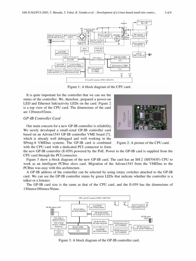
Figure 1 shows a block diagram of the CPU card. The CPU card employs a cost-effective 240MHz
SH-4 (SH7751R) CPU, which provides satisfactory performance as a distributed controller. The SH-4
CPU is suitable for both the PD and embedded system due to low power consumption. The main
memory is 64MB SDRAM, and the 32MB flash memory is used for a boot ROM for SH-Linux.
The CPU card has peripheral interfaces of a 10/100 Base-TX Ethernet port with PoE function, an
RS-232C port, and a USB 2.0 port. A PCI interface is also prepared using a dedicated small connector
in order to combine the I/O card.
The CPU card receives the electric power either from the Ethernet connector by the PoE or a
DC+5V input connector. The PD has to accept both alternatives of power supply methods as defined
in the IEEE802.3af. Alternative-A uses the signal pairs (pins 1, 2, and 3, 6) and alternative-B uses the
spare pairs (pins 4, 5 and 7, 8) of a CAT-5 cable in order to apply the DC voltage. The IEEE802.3af
compliant pulse transformer H2019 [5] is employed for the alternative-A in order to separate the data
signals and the DC voltage. Diode bridges are requested in order to handle the opposite polarity of the
DC voltage.
In order to provide the PoE signature and the power interface functions, the card employs
LCT4257-1 [6]. The 25k signature resistor is included in the chip. The LCT4257-1 simplifies the
design of the PD and helps to save the card space.
10th ICALEPCS 2005; T. Masuda, T. Fukui, R. Tanaka et al. : Development of a Linux-based small-size contro... 2 of 6
Ω
3.3V5V
flash memory (32MB)MBM29QM12DH60PCN
(x2)
SDRAM (64MB)MT48LC16M16A2TG-75
(x2)
Ethernet controller82551ER
Ethernet connectorTM11R-5M2-88-LP
pulse transformerH2019
PoE I/F controllerLTC4257CS8-1diode bridge
CMG02 x 8
flyback controllerLT1725CGN transformer
CEFD2010
Si4848DY
protection diodeRD68FM
48V
link/activity LEDslinear regulator
EZ1085CM
5V input connectorMJ-179P
SW regulatorLTC1753CSW
3.3V
1.5V
5V
reset ICMB3771PF(x2)
reset ICMB3771PF(x2)
CPU (SH-4)HD6417751RF240
SDRAM (64MB)MT48LC16M16A2TG-75
(x2)
flash memory (32MB)MBM29QM12DH60PCN
(x2)
JTAG ICEconnector
serialconnector
PCI clock generatorSG-8002JF(33.3MHz)
crystal oscillatorMEG35AD (48MHz)
serial ROMM93C46-WMN6
USB2.0 host controllerµPD720101F1-EA8
USB2.0 connectorUBA-4R-D14T-1
power SWLM3526M-H
PCI
I/O card I/F connctor (FX8C-140S-SV5)
isolation
It is quite important for the controller that we can see the
status of the controller. We, therefore, prepared a power-on
LED and Ethernet link/activity LEDs on the card. Figure 2
is a top view of the CPU card. The dimensions of the card
are 120mm 92mm.
GP-IB Controller Card
Our main concern for a new GP-IB controller is reliability.
We newly developed a small-sized GP-IB controller card
based on an Advme1543 GP-IB controller VME board [7],
which is already well debugged and well working in the
SPring-8 VMEbus systems. The GP-IB card is combined
with the CPU card with a dedicated PCI connector to form
the new GP-IB controller (E-059) powered by the PoE. Power to the GP-IB card is supplied from the
CPU card through the PCI connector.
Figure 3 show a block diagram of the new GP-IB card. The card has an SH-2 (SH7045F) CPU to
work as an intelligent PCIbus slave card. Migration of the Advme1543 from the VMEbus to the
PCIbus was easy with this architecture.
A GP-IB address of the controller can be selected by using rotary switches attached to the GP-IB
card. We can see the GP-IB controller status by green LEDs that indicate whether the controller is a
talker or a listener.
The GP-IB card size is the same as that of the CPU card, and the E-059 has the dimensions of
130mm 100mm 30mm.
CPU card I/F connctor (FX8C-140P-SV6)
5V 3.3V
linear regulatorSC15651S-2.5
2.5V
PCI I/F FPGAXC2S50-5PQ208C
serial ROMXC17S50A-PD8C
DP-RAM (64KB)CY7C102CV33-15VC
GP-IB I/F FPGAXC2S50-5TQ144C
SRAM (2MB)TC55NEM208AFTN55
(x4)
SRAM (2MB)TC55NEM208AFTN55
(x4)
SRAM (2MB)TC55NEM208AFTN55
(x4)
SRAM (2MB)TC55NEM208AFTN55
(x4)
CPU (SH-2)HD64F7045F28
built-in flashmemory (256kB)
(firmware)
serialconnector
serial ROMXC17S50A-PD8C
GP-IB transceiverSN75160BDW
GP-IB transceiverSN75162BDW
GP-IB connector57LE-20240-7700D35G
GP-IB status LEDs
GP-IB address S/W
Figure 2: A picture of the CPU card.
Figure 3: A block diagram of the GP-IB controller card.
Figure 1: A block diagram of the CPU card.
10th ICALEPCS 2005; T. Masuda, T. Fukui, R. Tanaka et al. : Development of a Linux-based small-size contro... 3 of 6
× ×
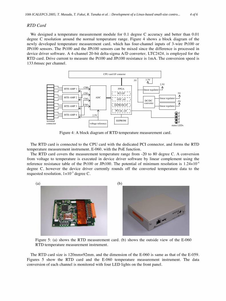
RTD Card
We designed a temperature measurement module for 0.1 degree C accuracy and better than 0.01
degree C resolution around the normal temperature range. Figure 4 shows a block diagram of the
newly developed temperature measurement card, which has four-channel inputs of 3-wire Pt100 or
JPt100 sensors. The Pt100 and the JPt100 sensors can be mixed since the difference is processed in
device driver software. A 4-channel 20-bit delta-sigma A/D converter, LTC2424, is employed for the
RTD card. Drive current to measure the Pt100 and JPt100 resistance is 1mA. The conversion speed is
133.6msec per channel.
CPU card I/F connctor
3.3V5V
linear regulator
2.5V
DC/DC converter
linear regulator
linear regulator
5V
-5V
FPGARTD AMP 1
RTD AMP 2
RTD AMP 3
RTD AMP 4
ADC
CH3
CH2
CH1
CH0
EEPROM
voltage reference
2.5V
PCI I/F
ADC ctrl
EEPROM I/F
PCI int. ctrl
status LEDs
terminal connector
The RTD card is connected to the CPU card with the dedicated PCI connector, and forms the RTD
temperature measurement instrument, E-060, with the PoE function.
The RTD card covers the measurement temperature range from -20 to 80 degree C. A conversion
from voltage to temperature is executed in device driver software by linear complement using the
reference resistance table of the Pt100 or JPt100. The potential of minimum resolution is 1.24 10-4
degree C, however the device driver currently rounds off the converted temperature data to the
requested resolution, 1 10-3 degree C.
(a) (b)
The RTD card size is 120mm 92mm, and the dimension of the E-060 is same as that of the E-059.
Figures 5 show the RTD card and the E-060 temperature measurement instrument. The data
conversion of each channel is monitored with four LED lights on the front panel.
Figure 5: (a) shows the RTD measurement card. (b) shows the outside view of the E-060
RTD temperature measurement instrument.
Figure 4: A block diagram of RTD temperature measurement card.
10th ICALEPCS 2005; T. Masuda, T. Fukui, R. Tanaka et al. : Development of a Linux-based small-size contro... 4 of 6
×
×
×

SH-Linux and Device Drivers
We have successfully migrated the operating system SH-Linux [8] to the CPU card. We used the
2.4.14 kernel of the SH-Linux. Device drivers for the GP-IB card and the RTD card were successfully
developed after the migration of the SH-Linux.
Since the new controller has no large storage device on the card, we introduce NFSroot, which uses
the NFS file system exported by the NFS server as a root device. The kernel image can be loaded from
and written into the flash memory on the CPU card. The NFSroot is quite convenient for the multi
target environment because we can manage the SH-Linux package on the NFS server machine. The
differences between the target controllers such as IP address and mount-point of the NFSroot are given
in the kernel parameters at boot time. Once we set the kernel parameters and save them into the flash
memory, the target controller automatically boots up with its own environment.
The 2.4.14 kernel doesn’t completely support the USB device, and we did not develop the USB
driver for the 2.4.14 kernel, so that the USB port is currently unavailable.
EXAMINATIONS
We examined the newly developed controllers by using an IEEE802.3af compliant PoE switching
hub, Switch M24PWR [9], as the PSE. The M24PWR is an intelligent hub and provides the web-based
management tools including the PoE function settings.
PoE Drive Test
We tested the PoE drive performance of the new controllers including the PD detection by the PSE.
We used 4 types of CAT-5e cables, i.e. a 5m long UTP (unshielded twisted pair) cable, a 5m long STP
(shielded twisted pair) cable, a 100m long UTP cable and a 100m long STP cable.
The PSE succeeded in the PD detection in all the types of CAT-5e cables. However, the PSD
frequently took a long time (about 30sec) to detect the PD only for the 100m long STP cable. Once the
PSE succeeded in the PD detection, the power feeding to the PD was very stable and kept as long as
the CAT-5e cable was connected.
The PSE management tool showed the E-059 GP-IB controller (E-060 RTD instrument) consumed
the power of 4.1W (3.7W), respectively. We can reset the controllers from the remote place using a
web browser since the PSE management tool can turn on and off the power of each port.
Temperature Measurement
We examined the temperature measurement
accuracy of the E-060 using 99.95 high
precision resistor, which guarantees a stability
of 5ppm/1 degree C. The E-060 was connected
to the PSE either using a 5m long UTP cable,
5m long STP cable, or a 100m long STP cable.
We accumulated 3600 data points with data
sampling rate of 1Hz. As shown in Figure 6,
the standard deviations become ±0.0016 and
±0.0018 degree C. The results are good enough
for our applications since our target accuracy is
0.1 degree C. We will measure the same
property under the RF noise environment.
The difference between the results of using
STP cables and a UTP cable is caused by the
frame ground of the Ethernet connector. Data
taken by the UTP cable shifted at -0.128 degree
C when the ground of the Ethernet connector
was connected to the PSE frame ground. The measurement result using a higher precision DMM
indicated that data of -0.128 degree C was close to the real value.
Figure 6: Results of the temperature
measurement accuracy of the E-060 using 99.95 high-precision resistor.
10th ICALEPCS 2005; T. Masuda, T. Fukui, R. Tanaka et al. : Development of a Linux-based small-size contro... 5 of 6
Ω
Ω
MADOCA Migration
We migrated the MADOCA (Message And Database Oriented Control Architecture) framework
[10] to the newly developed small-sized controller. The device control server process named
Equipment Manager [11] is stably running on the controller. We can incorporate the controller
smoothly into the VMEbus-based control system with the MADOCA control framework. We
succeeded in developing application software flexibly on the distributed controllers.
APPLICATIONS
We will install the E-060 RTD instruments into the SCSS test accelerator [12] in order to measure
the air temperatures and the wall temperatures in the accelerator tunnel. The E-060 instruments
covered by radiation protection boxes will be installed in the tunnel. Since the E-060 generates less
heat, thermal problems of the E-060s will not occur if the box has a certain volume. The compact PoE
measurement box is useful to reduce the wiring works of the Pt100 sensors.
We will also replace VMEbus GP-IB boards with the E-059s because the GP-IB sometimes makes
troubles on the VMEbus. The stability of the VMEbus system is expected to become higher by the
GP-IB board removal.
FUTURE PLANS
We have plans to develop an analog input card of ±10V range and a digital I/O card. We will also
use the CPU card as an Ethernet-to-RS232C converter without an I/O card.
Currently, we cannot use the USB port of the CPU card due to the problem of the device driver of
the 2.4 kernel. In order to solve the problem, we will port the SH-Linux2.6 kernel to the CPU card to
support the USB port.
SUMMARY
We have succeeded in developing the new Linux-based small-size controllers using the PoE
technology. The controllers are stably working with the ported SH-Linux and the MADOCA
framework. Practically, the PoE technology is convenient for the quick setting, cost effective with no
power line, and considerably enhances the degree of freedom of the installations with the compact
controller size. Since we can monitor the controller status and reset the controller from the remote
places by using the network-based PSE management tool, we can enhance the controllability of the
distributed controllers.
A measurement of the temperature by the E-060 shows the PoE technology can be applied not only
to digital devices but also to analog devices.
REFERENCES
[1] National Instruments Corporation, http://www.ni.com/
[2] Shinyei Kaisha, http://www.shinei.co.jp/ENG/kik/index-e.html/
[3] IEEE Std 802.3af -2003, http://standards.ieee.org/getieee802/download/802.3af-2003.pdf
[4] http://www.advanet.co.jp/en/
[5] Pulse Engineering, Inc., http://www.pulseeng.com/
[6] Linear Technology Corporation, http://www.linear.com/
[7] Advanet Inc., http://www.advanet.co.jp/en/
[8] http://www.sh-linux.org/
[9] Matsushita Network Operations Co., Ltd., http://www.mno.co.jp/ (Japanese)
[10] R. Tanaka et al., “The first operation of control system at the SPring-8 storage ring”, Proc. of
ICALEPCS'97, Beijing, China, 1997, p 1.
[11] A. Taketani et al., “Equipment Manager of the VME Control System for the SPring-8 Storage
Ring”, ICALEPCS’95, Chicago, USA, 1995, p.625.
[12] T. Fukui et al., “Status of the SCSS control system – first phase of an 8GeV XFEL project in
SPring-8”, in these proceedings.
10th ICALEPCS 2005; T. Masuda, T. Fukui, R. Tanaka et al. : Development of a Linux-based small-size contro... 6 of 6