development and implementation of the next generation...
TRANSCRIPT


1 | P a g e
This page intentionally left blank

2 | P a g e
Technical Report Documentation Page
1. Report No. 0092-13-06
2. Government Accession No
3. Recipient’s Catalog No
4. Title and Subtitle Development and Implementation of the Next Generation Bridge Management System for Wisconsin Phase I
5. Report Date April 2014 6. Performing Organization Code
7. Authors Jose Aldayuz
8. Performing Organization Report No.
9. Performing Organization Name and Address Michael Baker International 3601 Eisenhower Avenue Alexandria, VA 22304
10. Work Unit No. (TRAIS) 11. Contract or Grant No. WisDOT Project No. 0092-13-06
12. Sponsoring Agency Name and Address Wisconsin Department of Transportation Research & Library Unit 4802 Sheboygan Ave. Madison, WI 53707
13. Type of Report and Period Covered Final Report, 2013-2016 14. Sponsoring Agency Code
15. Supplementary Notes
16. Abstract With the enactment of the Moving Ahead for Progress in the 21st Century (MAP-21) legislation, each state must report element-level data to the Secretary of Transportation within two years. All highway bridges on the National Highway System (NHS) will need to be inspected pursuant to the revised standards that entail using the 2013 AASHTO Manual for Bridge Element Inspection for National Bridge Elements (NBEs), Bridge Management Elements (BMEs), and Agency Defined Elements (ADEs). In the case of the state of Wisconsin, NHS and non-NHS structures will be inspected with the new AASHTO elements. This interim report describes the process used to convert the CoRe Structural Element Data to the NBEs, BMEs, and ADEs using the AASHTO Element Migrator from the current HSI to a new version of the HSI capable of assimilating bridge inspection information in compliance with the MAP-21 requirements. The report includes three distinct sections. The first section describes the process used to extract the CoRe bridge inspection information from the existing HSI, the development of the migration rules for all the bridge elements in the HSI, and the use of the AASHTO Migration Tool (Migrator) to develop an XML file with the results of the migration process. The second section outlines the development of a software application utility created to import the XML files from the Migrator to a revised version of the HSI. The third section contains appendices summarizing the literature research and the file names for the SQL code developed to complete Phase 1 of this project outlined in the deliverables for each section. This report also includes a section with recommendations to place WisDOT in a strategic position to export HSI information to forecast bridge needs and prioritize bridge preservation and replacement work using the BrM 5.2.X software to be released in 2015.
17. Bridges, bridge members, inspections
18. Distribution Statement
No restriction. This document is available to the public through the National Technical Information Service 5285 Port Royal Road Springfield VA 22161
18. Security Classif.(of this report) Unclassified
19. Security Classif. (of this page) Unclassified
20. No. of Pages
21. Price

3 | P a g e
Disclaimer
This research was funded through the Wisconsin Highway Research Program by the
Wisconsin Department of Transportation and the Federal Highway Administration under Project
No. 0092-13-06. The contents of this report reflect the views of the authors who are responsible
for the facts and accuracy of the data presented herein. The contents do not necessarily reflect
the official views of the Wisconsin Department of Transportation or the Federal Highway
Administration at the time of publication.
This document is disseminated under the sponsorship of the Department of
Transportation in the interest of information exchange. The United States Government assumes
no liability for its contents or use thereof. This report does not constitute a standard,
specification or regulation.
The United States Government does not endorse products or manufacturers. Trade and
manufacturers’ names appear in this report only because they are considered essential to the
object of the document.

4 | P a g e
Table of Contents
Disclaimer...................................................................................................................................................... 3
Background ................................................................................................................................................... 5
CoRe HSI Bridge Inspection Information Migration Process ........................................................................ 6
Evaluating the HSI CoRe Element Data ..................................................................................................... 6
Extracting and Reorganizing the Existing HSI Data for Migration ............................................................. 8
Transforming the Data for Migration to BrM/Pontis for Testing ........................................................... 15
New HSI Migrated Data Import Process ..................................................................................................... 16
Mapping of Migrated Element Data to New HSI Database ................................................................ 20
Mapping Description ........................................................................................................................... 20
XML Import Application Description ....................................................................................................... 22
BrM 5.2.X Future Database Changes ...................................................................................................... 40
Recommendations .................................................................................................................................. 42
Condition State Language ................................................................................................................... 42
Export/Import to BrM 5.2.3 ................................................................................................................ 42
Annual Report to FHWA ...................................................................................................................... 42
Appendix A—Literature Review .................................................................................................................. 43

5 | P a g e
Background The state of Wisconsin bridge network system consists of 14,022 structures that carry highway traffic.
There are 5,196 state-owned bridges and 8,826 bridges owned by local units of government. Routine
inspections for all of these bridges are conducted once every two years in accordance with federal
requirements. All bridges in the network are inspected using the National Bridge Inspection (NBI)
ratings, as well as bridge element condition ratings. The dual inspection of the bridge structures in the
network began in 1998 using the AASHTO Guide for Commonly Recognized (CoRe) Structural Elements,
published in 1997.
With the enactment of the Moving Ahead for Progress in the 21st Century (MAP-21) legislation, each
state must report element-level data to the Secretary of Transportation within two years. All highway
bridges on the National Highway System (NHS) will need to be inspected pursuant to the revised
standards that entail using the 2013 AASHTO Manual for Bridge Element Inspection for National Bridge
Elements (NBEs), Bridge Management Elements (BMEs), and Agency Defined Elements (ADEs). In the
case of the state of Wisconsin, NHS and non-NHS structures will be inspected with the new AASHTO
elements.
The Wisconsin Deportment of Transportation (WisDOT) uses their Highway Structures Information
System (HSI) to collect and store bridge and other transportation asset inspection information. The goal
of this system is to assist with the implementation of a strategic approach to maximize the benefits from
resources used to preserve, operate, and expand their structures network. In order to provide the
system with a solid foundation under the MAP-21 requirements, a conversion of the CoRe Structural
Elements to the AASHTO 2013 National Bridge Elements and Bridge Management Elements is needed.
This interim report describes the process used to convert the CoRe Structural Element Data to the NBEs,
BMEs, and ADEs using the AASHTO Element Migrator from the current HSI to a new version of the HSI
capable of assimilating bridge inspection information in compliance with the MAP-21 requirements. The
report includes three distinct sections. The first section describes the process used to extract the CoRe
bridge inspection information from the existing HSI, the development of the migration rules for all the
bridge elements in the HSI, and the use of the AASHTO Migration Tool (Migrator) to develop an XML file
with the results of the migration process. The second section outlines the development of a software
application utility created to import the XML files from the Migrator to a revised version of the HSI. The
third section contains appendices summarizing the literature research and the file names for the SQL
code developed to complete Phase 1 of this project outlined in the deliverables for each section.
This report also includes a section with recommendations to place WisDOT in a strategic position to
export HSI information to forecast bridge needs and prioritize bridge preservation and replacement
work using the BrM 5.2.X software to be released in 2015.

6 | P a g e
CoRe HSI Bridge Inspection Information Migration Process The data migration process was planned with the knowledge that WisDOT maintains its element data in
several related tables in the HSI that in combination were presented in a set of views that correspond to
the BrM/Pontis tables ELEMDEFS and ELEMINSP, which are the sources of data for the Migrator. The
Migrator software only understands and processes XML text data presented following its input and
output XML schemas, which are largely defined based on the Pontis element-related tables. This
requires all of the HSI data to be downloaded as XML files for processing by the Migrator. For
documentation purposes, it should be noted that the Migrator does not provide functionality to migrate
general structure information or general inspection information; it only migrates element specifications
and inspection results in two XML files.
The migration process entails three main steps:
Evaluating the HSI CoRe element data.
Extracting and reorganizing the existing HSI data for migration.
Transforming the data for migration to BrM/Pontis for testing.
Evaluating the HSI CoRe Element Data This step entails the enumeration of all the element types used in Wisconsin, the verification that
element ID and element TYPE codes are consistent with the Migrator input XML schema, and the
identification of variances. Close coordination with the Project Oversight Committee (POC) was followed
to document the relationship of WisDOT elements to the new AASHTO elements. The wall elements in
the HSI are not included in this project.
A few iterations were needed to:
Identify any elements that are to be deprecated and/or combined into new AASHTO elements
during this process.
Identify element characteristics affecting migration, such as number of condition states for each
element.
Identify any needed transformation rules for WisDOT specific elements, including rules for the
WisDOT elements not found in the standard rule set, as well as those that are at variance with
the assumptions or specifications of the standard Migrator rules.
Confirm that element data state quantities add up to element total quantities.
A list of Assessments (physical element structure or site condition) was compiled by the WisDOT BOS
and reviewed with the POC and the Research Team. The Assessments were treated in the same manner
as the 2013 AASHTO elements, which is essentially the same as a Smart Flag/Defect to highlight an
element with a meaningful condition but no recommended actions.
7 | P a g e
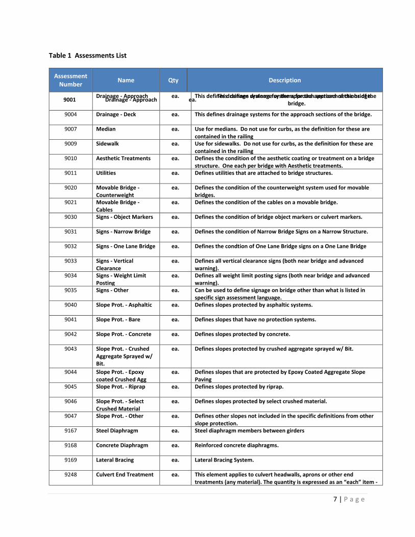
Table 1 Assessments List
Assessment Number
Name Qty Description
9001 Drainage - Approach ea. This defines drainage systems for the approach sections of the
bridge.
Drainage - Approach
ea.
This defines drainage systems for the approach sections of the bridge.
9004 Drainage - Deck ea. This defines drainage systems for the approach sections of the bridge.
9007 Median ea. Use for medians. Do not use for curbs, as the definition for these are contained in the railing
9009 Sidewalk ea. Use for sidewalks. Do not use for curbs, as the definition for these are contained in the railing
9010 Aesthetic Treatments ea. Defines the condition of the aesthetic coating or treatment on a bridge structure. One each per bridge with Aesthetic treatments.
9011 Utilities ea. Defines utilities that are attached to bridge structures.
9020 Movable Bridge - Counterweight
ea. Defines the condition of the counterweight system used for movable bridges.
9021 Movable Bridge - Cables
ea. Defines the condition of the cables on a movable bridge.
9030 Signs - Object Markers ea. Defines the condition of bridge object markers or culvert markers.
9031 Signs - Narrow Bridge ea. Defines the condition of Narrow Bridge Signs on a Narrow Structure.
9032 Signs - One Lane Bridge ea. Defines the condtion of One Lane Bridge signs on a One Lane Bridge
9033 Signs - Vertical Clearance
ea. Defines all vertical clearance signs (both near bridge and advanced warning).
9034 Signs - Weight Limit Posting
ea. Defines all weight limit posting signs (both near bridge and advanced warning).
9035 Signs - Other ea. Can be used to define signage on bridge other than what is listed in specific sign assessment language.
9040 Slope Prot. - Asphaltic ea. Defines slopes protected by asphaltic systems.
9041 Slope Prot. - Bare ea. Defines slopes that have no protection systems.
9042 Slope Prot. - Concrete ea. Defines slopes protected by concrete.
9043 Slope Prot. - Crushed Aggregate Sprayed w/ Bit.
ea. Defines slopes protected by crushed aggregate sprayed w/ Bit.
9044 Slope Prot. - Epoxy coated Crushed Agg
ea. Defines slopes that are protected by Epoxy Coated Aggregate Slope Paving
9045 Slope Prot. - Riprap ea. Defines slopes protected by riprap.
9046 Slope Prot. - Select Crushed Material
ea. Defines slopes protected by select crushed material.
9047 Slope Prot. - Other ea. Defines other slopes not included in the specific definitions from other slope protection.
9167 Steel Diaphragm ea. Steel diaphragm members between girders
9168 Concrete Diaphragm ea. Reinforced concrete diaphragms.
9169 Lateral Bracing ea. Lateral Bracing System.
9248 Culvert End Treatment ea. This element applies to culvert headwalls, aprons or other end treatments (any material). The quantity is expressed as an “each” item - on a typical culvert, the quantity will be “2” (one for each end).

8 | P a g e
Assessment Number
Name Qty Description
9250 Cross Bracing or Struts ea. Defines all types of cross bracing systems not defined by other elements.
9290 Dolphin or Fender System
ea. Defines systems used to protect bridge substructure units from vessel collisions.
9322 Approach Roadway - Concrete (non-structural)
ea. This defines approach roadway sections that are concrete but are not designed as a structural slab.
9323 Approach Roadway - Asphalt
ea. This defines approach roadway sections that are composed of asphalt.
9324 Approach Roadway - Gravel
ea. This defines approach roadway sections that are composed of gravel.
9325 Roadway Over Structure
ea. This element defines the roadway over a buried culvert or arch where there is more than 9" of fill.
9335 Decorative Rail ea. Non-structural decorative
9336 Luminaire Bases ea. Defines the base unit of Luminaire supports typically located on traffic railing on the bridge.
9337 Protective Screening ea. Protective screening or fencing on a bridge structure.
Deliverable: Review/Update of a Microsoft Excel workbook file with tabs for Bridge Elements, New
Element Definitions, Defects, Assessment Definitions, and Wall Elements (see the following
graphic). The protective System Relationships and Defect Relationships tabs were created
later by the WisDOT BOS.
Extracting and Reorganizing the Existing HSI Data for Migration This step is needed to present the element HSI data in a format consistent with the Migrator
requirements. Using Structured Query Language (SQL), ”Cloaking” Tables and Views need to be created
to imitate the Pontis 4.x table equivalents that the Migrator is designed to read.
9 | P a g e
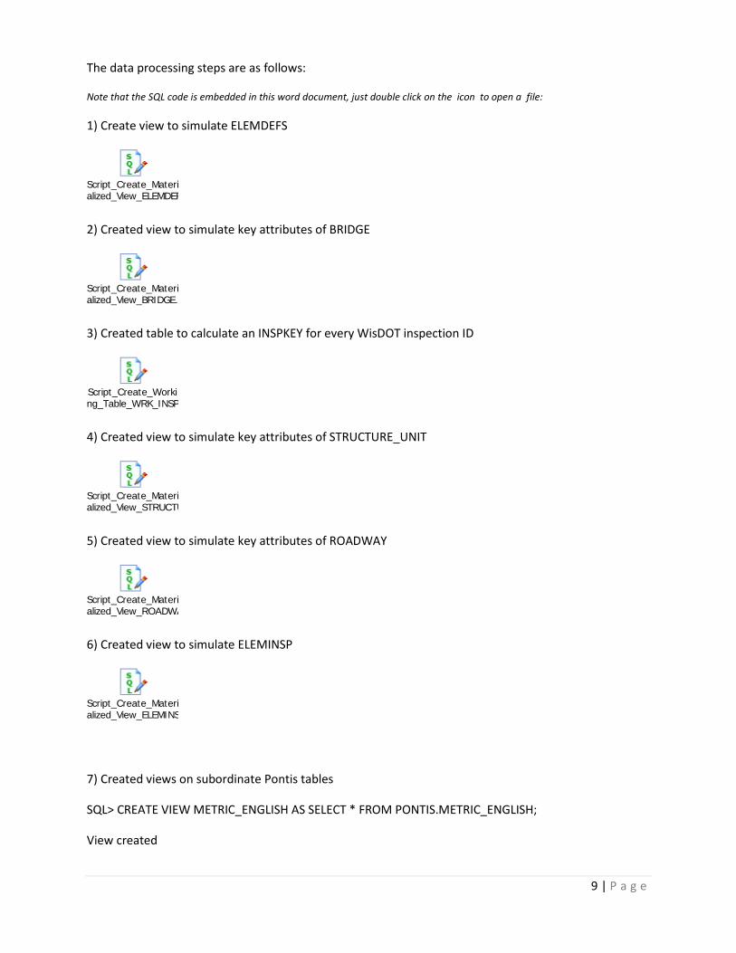
The data processing steps are as follows:
Note that the SQL code is embedded in this word document, just double click on the icon to open a file:
1) Create view to simulate ELEMDEFS
Script_Create_Materialized_View_ELEMDEFS.sql
2) Created view to simulate key attributes of BRIDGE
Script_Create_Materialized_View_BRIDGE.sql
3) Created table to calculate an INSPKEY for every WisDOT inspection ID
Script_Create_Working_Table_WRK_INSPKEYS.sql
4) Created view to simulate key attributes of STRUCTURE_UNIT
Script_Create_Materialized_View_STRUCTURE_UNIT.sql
5) Created view to simulate key attributes of ROADWAY
Script_Create_Materialized_View_ROADWAY.sql
6) Created view to simulate ELEMINSP
Script_Create_Materialized_View_ELEMINSP.sql
7) Created views on subordinate Pontis tables
SQL> CREATE VIEW METRIC_ENGLISH AS SELECT * FROM PONTIS.METRIC_ENGLISH;
View created
10 | P a g e
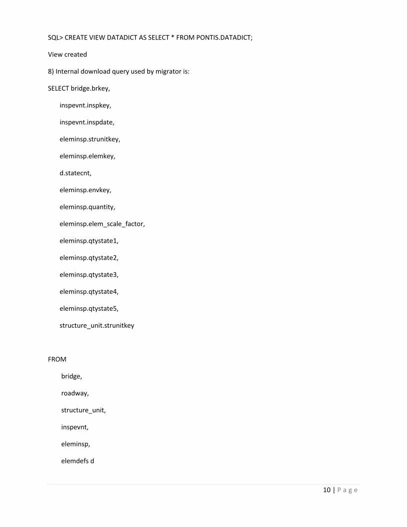
SQL> CREATE VIEW DATADICT AS SELECT * FROM PONTIS.DATADICT;
View created
8) Internal download query used by migrator is:
SELECT bridge.brkey,
inspevnt.inspkey,
inspevnt.inspdate,
eleminsp.strunitkey,
eleminsp.elemkey,
d.statecnt,
eleminsp.envkey,
eleminsp.quantity,
eleminsp.elem_scale_factor,
eleminsp.qtystate1,
eleminsp.qtystate2,
eleminsp.qtystate3,
eleminsp.qtystate4,
eleminsp.qtystate5,
structure_unit.strunitkey
FROM
bridge,
roadway,
structure_unit,
inspevnt,
eleminsp,
elemdefs d

11 | P a g e
WHERE (bridge.brkey = eleminsp.brkey AND
bridge.brkey = roadway.brkey AND
roadway.on_under =
(SELECT MIN(r2.on_under)
FROM roadway r2
WHERE r2.brkey = bridge.brkey)) AND
bridge.brkey=structure_unit.brkey AND
structure_unit.strunitkey = eleminsp.strunitkey AND
bridge.brkey = inspevnt.brkey AND
inspevnt.inspkey = eleminsp.inspkey AND
d.elemkey = eleminsp.elemkey /*AND
inspevnt.inspdate >= ? {0}*/
ORDER BY bridge.brkey,
inspevnt.inspdate DESC,
inspevnt.inspkey,
eleminsp.elemkey,
eleminsp.strunitkey,
eleminsp.envkey
9) Updated INSPEVNT,ELEMINSP materialized views and the related table WRK_INSPKEYS
a) Add an index to DT_STIN_ITEM
-- Create/Recreate primary, unique and foreign key constraints
alter table DT_STIN_ITEM

12 | P a g e
add constraint DT_STIN_ITEM_PK01 primary key (STIN_ID, STIN_ELMT_CD,
STIN_ELMT_ENVR_NB)
using index
tablespace PROJNDX
pctfree 0
initrans 2
maxtrans 255
storage
(
initial 160K
next 1M
minextents 1
maxextents unlimited
);
b) Create the table WRK_INSPKEYS
Script_Create_Working_Table_WRK_INSPKEYS.sql
This step is used to run lines 31 to 58 of the script
c) Create the materialized view INSPEVNT. It has only a partial image of the Pontis INSPEVNT
table - enough to query on from the Migrator
see file >>> Script_Create_Materialized_View_INSPEVNT.sql
>>> Generates 138,872 synthetic rows
DROP MATERIALIZED VIEW INSPEVNT;

13 | P a g e
CREATE MATERIALIZED VIEW INSPEVNT
REFRESH FORCE ON DEMAND
AS
SELECT inspkeys.strc_id AS BRKEY, inspkeys.INSPKEY, insp.stin_dt as INSPDATE, insp.stin_tycd
as STIN_TYCD
FROM WRK_INSPKEYS inspkeys INNER JOIN dt_strc_insp insp
on inspkeys.strc_id = insp.strc_id and inspkeys.stin_id = insp.stin_id and
UPPER(TRIM(insp.stin_tycd)) IN ('R' , 'INI');
d) Create the materialized view ELEMINSP
This is the FULL image of the INSPEVNT table
see file >>> Script_Create_Materialized_View_ELEMINSP.sql
>>> Generates 1,295,746 synthetic rows
10) Exported generated data from INSPEVNT and ELEMINSP again.
11) Download all data to Migrator from ELEMINSP materialized view (synthetic data)
12) Migration rules modifications for 2013-07-30
a) Rules changed to migrate all WisDOTslope protection types to 9010 - generic
b) Rules changed to migate WisDOT 148 to 8165
c) Rules removed for 146 and 147
d) Rules changed to force WisDOT curb 410 to sidewalks assessment 9009
e) Rules changed to force WisDOT sidewalks/medians 415 to median assessment 9007
f) All WisDOT wingwalls now go to 8608 'Other Walls'
g) WisDOT 172 and 171 go to 8167 Steel Diaphragm
14 | P a g e
h) WisDOT 250 goes to 8168 Concrete Diaphragm
i) WisDOT 174 and 175 go to 8169 Lateral Bracing (as far as I can stell, there are only steel elements
for this.)
j) WisDOT 236 goes to 8250 - X-bracing (only timber as far as I can tell).
k) WisDOT 405 goes to 9004 - Deck drainage. It is impossible to tell if 405 is deck or approach
drainage - requires field verification.
l) WisDOT 340,341,342,343,344 slope protections go to generic slope protection assessment 9010
13) Attempted and succeeded migrating data for districts 1 and 7 following the migrator instructions to
connect to the database.
During the testing phase, some minor issues with quantities were found and solved with direction from
the POC. Also, the migrator filter was adjusted to retrieve only the appropriate inspection types and to
select just the last inspection per bridge.
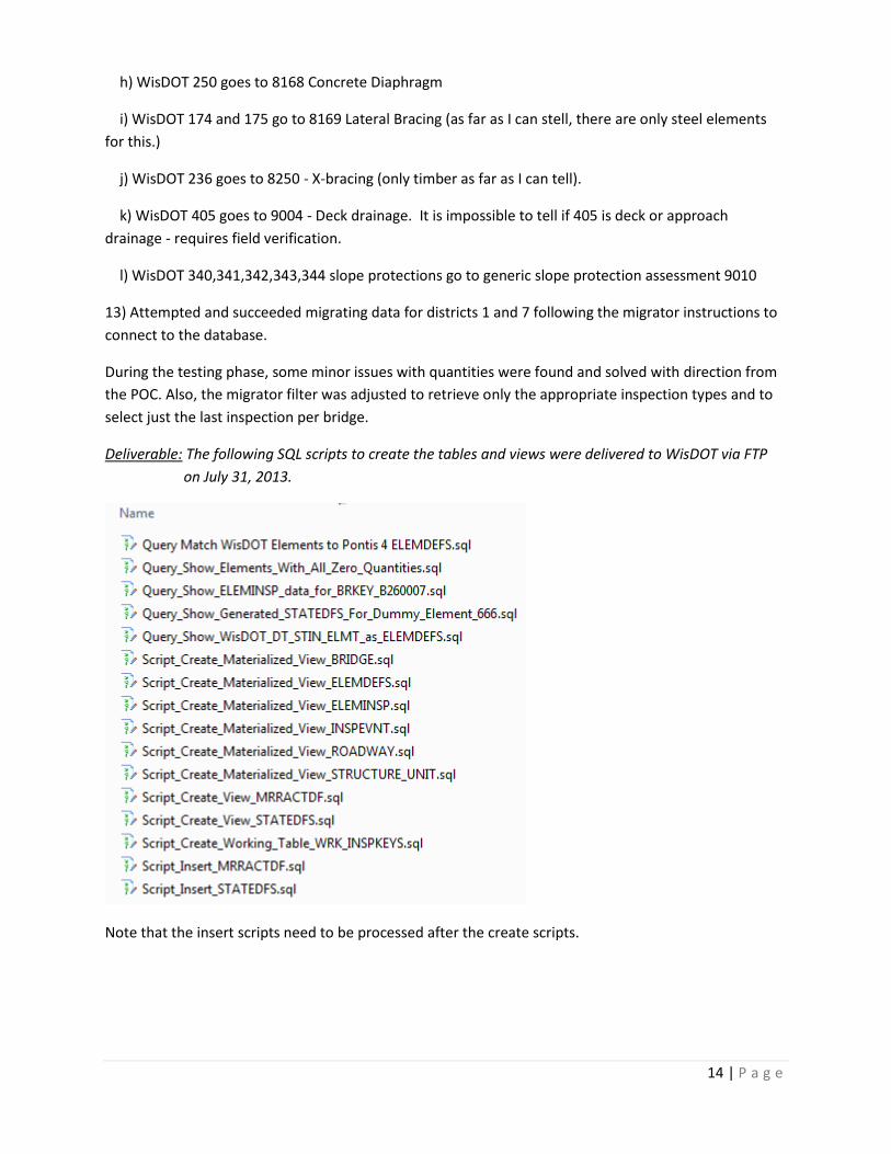
Deliverable: The following SQL scripts to create the tables and views were delivered to WisDOT via FTP
on July 31, 2013.
Note that the insert scripts need to be processed after the create scripts.

15 | P a g e
Transforming the Data for Migration to BrM/Pontis for Testing The third and final step of the migration process consists of importing the existing WisDOT element
specifications XML file using the Migrator. During the test phase, the element definitions file was
successfully verified to work with the Pontis 5.1.3 release provided by WisDOT.
The steps followed to test the import the XML into Pontis 5.1.3 are:
1. Edit the NBI file to change the bridge_id column to remove the bridge_id trailing zeroes to
match the XML migrator format
2. Import the edited NBI file into an empty Pontis 5.1.3 database
3. Make sure that the elemddefs table rows, match the Element definition XML File
4. Import the XML element data from the Migrator Results
At this point, the existing (default) migration rules were updated to process WisDOT elements where
applicable and new rules for Agency Defined Elements (ADEs) were created. The validation of all
element migration rules was completed using the imported elements specification XML file.
The element specifications file from the Migrator is one of the necessary inputs to the Pontis 5.1.3 BMS
and is also needed in the new HSI database. By design, the file lacks condition state and actions
language. A manual or automated process is needed to write the condition state and actions language
for the elements. The HSI database information contains dimensional quantities in English units, so the
XML file input and output must be set to this unit system, as shown below.
In accordance with the Work Plan, to verify compliance with AASHTO standards, the Migrator files were
tested using the following iterative process:
Applied transformation rules to generate output XML files
Reviewed results with the POC and corrected some rules as requested
Imported XML selected bridge inspections to test BrM/Pontis 5.1.3 database

16 | P a g e
Deliverable: Migration Rules File, XML Element Definition File, and XML Migrated Data File delivered on
August 26, 28, and 29, 2013, respectively.
New HSI Migrated Data Import Process This section describes the process used to import the two Migrator XML files to a new HSI Oracle
database modified by WisDOT to accommodate BrM/Pontis 5.1.3 conventions. The current and new HSI
databases were reviewed in order to identify their differences in terms of the tables relevant to bridge
inspection information.
The following entity-relationship diagram shows the current HSI database tables where the CoRe bridge
element inspection data is stored.

17 | P a g e

18 | P a g e
The next entity-relationship diagram shows the new HSI database structure where the converted CoRe
element data based on the XML element specification from the Migrator will be stored. The new tables
have their names shown in red font.
19 | P a g e
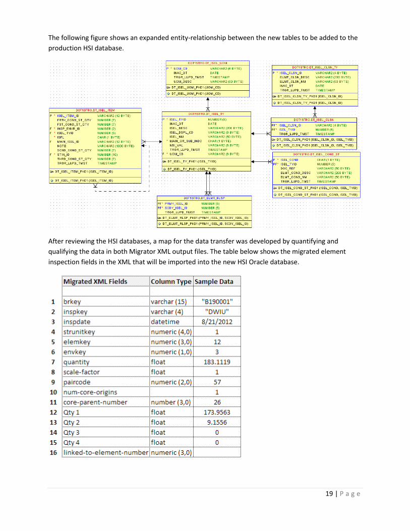
The following figure shows an expanded entity-relationship between the new tables to be added to the
production HSI database.
After reviewing the HSI databases, a map for the data transfer was developed by quantifying and
qualifying the data in both Migrator XML output files. The table below shows the migrated element
inspection fields in the XML that will be imported into the new HSI Oracle database.
20 | P a g e
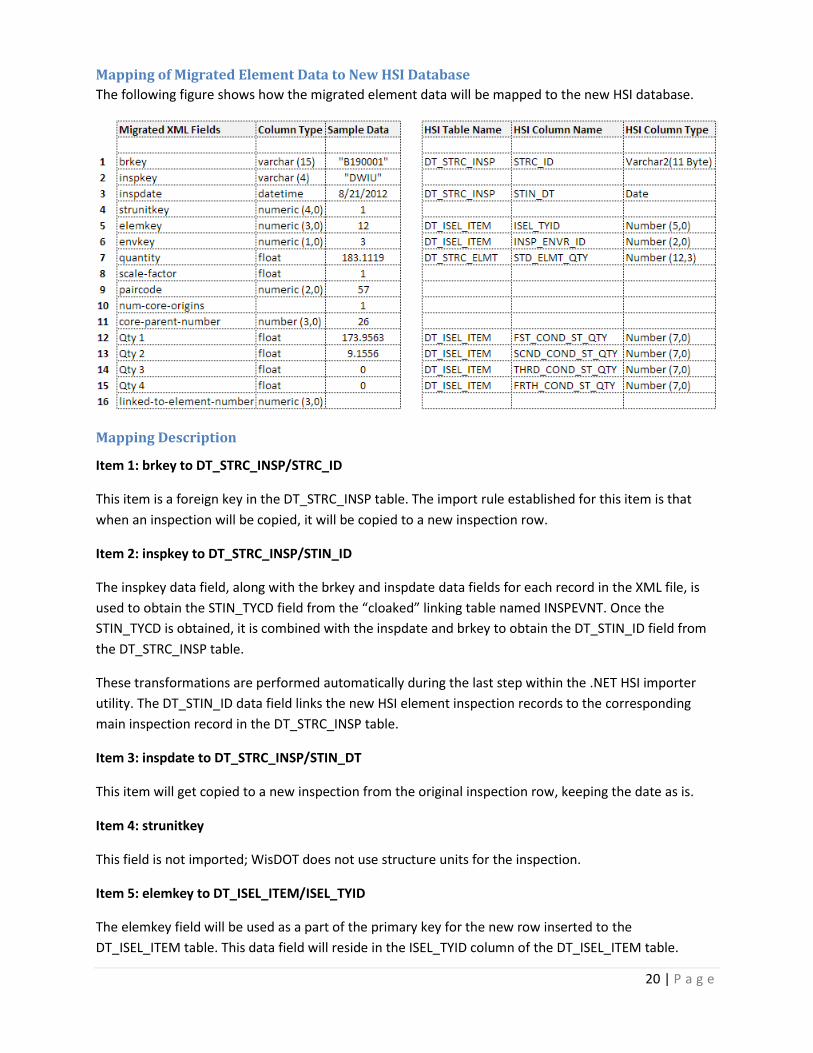
Mapping of Migrated Element Data to New HSI Database
The following figure shows how the migrated element data will be mapped to the new HSI database.
Mapping Description
Item 1: brkey to DT_STRC_INSP/STRC_ID
This item is a foreign key in the DT_STRC_INSP table. The import rule established for this item is that
when an inspection will be copied, it will be copied to a new inspection row.
Item 2: inspkey to DT_STRC_INSP/STIN_ID
The inspkey data field, along with the brkey and inspdate data fields for each record in the XML file, is
used to obtain the STIN_TYCD field from the “cloaked” linking table named INSPEVNT. Once the
STIN_TYCD is obtained, it is combined with the inspdate and brkey to obtain the DT_STIN_ID field from
the DT_STRC_INSP table.
These transformations are performed automatically during the last step within the .NET HSI importer
utility. The DT_STIN_ID data field links the new HSI element inspection records to the corresponding
main inspection record in the DT_STRC_INSP table.
Item 3: inspdate to DT_STRC_INSP/STIN_DT
This item will get copied to a new inspection from the original inspection row, keeping the date as is.
Item 4: strunitkey
This field is not imported; WisDOT does not use structure units for the inspection.
Item 5: elemkey to DT_ISEL_ITEM/ISEL_TYID
The elemkey field will be used as a part of the primary key for the new row inserted to the
DT_ISEL_ITEM table. This data field will reside in the ISEL_TYID column of the DT_ISEL_ITEM table.

21 | P a g e
Item 6: envkey to DT_ISEL_ITEM/INSP_EVNR_ID
Item 6 will be used as a part of the primary key for the new row inserted to the DT_ISEL_ITEM table. In
order to transfer the envkey field from the new migrated element inspections in the XML file, the
DT_INSP_ENVR table is first populated during one of the steps within the .NET HIS XML importer utility.
The current process only requires that the DT_INSP_ENVR table has four environments populated with
the INSP_ENVR_ID ranging from 1 through 4 representing the environment names Low, Moderate,
Severe, and Benign, respectively.
The determination of any changes necessary to these environment definitions while still maintaining the
validity of migrated element inspection data will be materialized during WisDOT internal review of new
HSI element inspection data as a part of the pilot inspection process.
Item 7: quantity to DT_STRC_ELMT/STD_ELMT_QTY
This item will not be imported since the total quantity of an element does not change during the
migration.
Item 8: scale-factor
This field will not be imported.
Item 9: paircode
This item will not be imported.
Item 10: num-core-origins
This item will not be imported.
Item 11: core-parent-number
This item will not be imported.
Item 12: Qty1 to DT_ISEL_ITEM/FST_COND_ST_QTY
Item 12 will be imported as part of the new element inspection row added to the DT_ISEL_ITEM table.
Item 13: Qty2 to DT_ISEL_ITEM/SCND_COND_ST_QTY
This data will be imported as part of the new element inspection row added to the DT_ISEL_ITEM table.
Item 14: Qty3 to DT_ISEL_ITEM/THRD_COND_ST_QTY
This data will be imported as part of the new element inspection row added to the DT_ISEL_ITEM table.
Item 15: Qty4 to DT_ISEL_ITEM/FRTH_COND_ST_QTY
This data will be imported as part of the new element inspection row added to the DT_ISEL_ITEM table.
Item 16: linked-to-element-number to DT_ISEL_ITEM/MAIN_ISEL_ID

22 | P a g e
This data will be used to locate the ISEL_ITEM_ID field of a parent HSI element inspection record in the
DT_ISEL_ITEM table to populate the MAIN_ISEL_ID field of a new element inspection record being
inserted.
Import Operation Implementation Plan
The following is a summary of the Import Operation Implementation Plan:
The data import application will first load the Element Definitions and Migrated Inspections XML
files.
The connection to the new HSI database will be established.
All new HSI database tables that are parent to the DT_ISEL_ITEM table will be read and
populated as necessary, including the following:
o The DT_ISEL_UOM table will be populated such that it is synchronized with unit of
measures used by the migrated element inspection dataset.
o The DT_ISEL_TY table will be populated by mapping element definitions used by the
migrated element inspection dataset.
For each element from the XML file, a corresponding main inspection record will be located in
the DT_STRC_INSP table using the STRC_TYCD and STIN_DT fields to obtain the STIN_ID field.
For each migrated element record in the XML file, a new row will be inserted into the
DT_ISEL_ITEM table with the sequential number generated for the primary key column
ISEL_ITEM_ID.
The foreign key INS_ENVR_ID and ISEL_TYID in the DT_ISEL_ITEM table will be populated from
the XML file data row. The STIN_ID field is populated as described in the fourth bullet of this
section.
The MAIN_ISEL_ID field will be populated with the ISEL_ITEM_ID field of the parent element
inspection record in the DT_ISEL_ITEM table for child inspections.
The DT_ISEL_ITEM inspection notes will be populated by migrating old HSI element inspection
data to new HSI element inspection data.
XML Import Application Description
Prerequisites
1. The test or production HSI Oracle database instance must have new empty HSI tables created.
2. The client machine where the application is to be installed must have the Oracle 11g (32 bit)
client software installed.
The database user account connection must have privileges to connect to the HSI
database and perform create, read, update, and delete (CRUD) operations. Preferably,
the connection user account should be the schema owner.
The client machine windows login must have privileges (preferably administrator) so
that importer application can be installed.
The client machine and/or windows login account must have privileges to allow the
installation of the NET 4.5 framework files. These are needed by the application.
The installer requires a Windows 7 operating system.

23 | P a g e
Pre-Installation Steps
1. Create a TNS Profile for HSI Oracle Database on the client machine.
Open Oracle Net Manager from Oracle 11g (32 bit) client software.
Create Service Naming for HSI database.
Test the connection and save the configuration.
2. Create an ODBC profile for the HSI Oracle Database on the client machine.
Open the 32-bit ODBC Data Source Administrator. This executable can be found in the
C:\Windows\SysWOW64 folder.
24 | P a g e
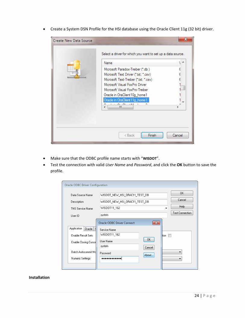
Create a System DSN Profile for the HSI database using the Oracle Client 11g (32 bit) driver.
Make sure that the ODBC profile name starts with “WISDOT”.
Test the connection with valid User Name and Password, and click the OK button to save the
profile.
Installation

25 | P a g e
a. Save and unzip the Install.zip file on the client machine.
b. Locate and run setup.exe from the Disk1 directory.
c. Follow the installation wizard to install the product.
d. Launch the application from the Start Menu\Programs\Baker WisDOT BMS folder.
e. The default application installation directory is C:\Program Files (x86)\Baker WisDOT BMS.
f. The application can be uninstalled using the Uninstall link from the Start Menu\Programs\Baker
WisDOT BMS folder.
Importing the Migrated Bridge Element Inspections
Step 1— Read Elem XML Tab
Use this tab to load the migrated element inspection XML data for the import process as follows:
a. Click the Select XML File button to open the select file dialog box.
b. Navigate to the Data folder in the installation directory C:\Program Files (x86)\Baker WisDOT BMS
folder.

26 | P a g e
c. Select the migrated xml data file named WisDOTAllDistrictsMigratedAASHTOElementDataLatestInspectionsOnly20130828.xml
d. Click the Load XML File button.
e. A message related to the successful loading of the xml file should be automatically displayed.

27 | P a g e
f. Click the Review Element Data button to load the data in the tree format organized by
bridge\inspection\element inspections parent and children. Click the bridge node in the tree and
drill down to the element inspections. Click each element inspection node to review individual
migrated element inspection details in the right pane.

28 | P a g e
Step 2— Connect to HSI DB Tab
The HSI DB tab allows the user to connect to the HSI database using the application. Users should ensure
that the correct credential and connection are being used, as verified via the ODBC Data Source
Administrator (32 bit).
To connect to the HSI database, follow the steps below:
a. Establish the connection by clicking the Connect button. Once connected, the Disconnect
button will be visible. The user may not disconnect until all the import steps are complete.
Caution: For convenience, the application filters ODBC DSN profiles by WISDOT prefix to avoid
populating numerous other DSN that are not relevant. Users must ensure that their ODBC DSN
profile name starts with the WISDOT key word.
29 | P a g e
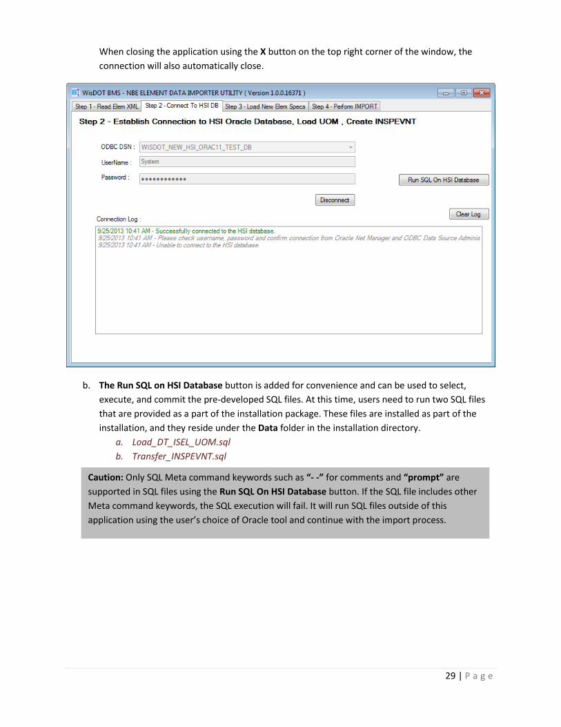
When closing the application using the X button on the top right corner of the window, the
connection will also automatically close.
b. The Run SQL on HSI Database button is added for convenience and can be used to select,
execute, and commit the pre-developed SQL files. At this time, users need to run two SQL files
that are provided as a part of the installation package. These files are installed as part of the
installation, and they reside under the Data folder in the installation directory.
a. Load_DT_ISEL_UOM.sql
b. Transfer_INSPEVNT.sql
Caution: Only SQL Meta command keywords such as “- -” for comments and “prompt” are
supported in SQL files using the Run SQL On HSI Database button. If the SQL file includes other
Meta command keywords, the SQL execution will fail. It will run SQL files outside of this
application using the user’s choice of Oracle tool and continue with the import process.

30 | P a g e
Select the Load_DT_ISEL_UOM.sql file, and click the Open button. This will open a new
window, as shown below. Click the Execute button to run the file on HSI database.
The Load_DT_ISEL_UOM.sql file will populate the DT_INSP_ENVR and DT_ISEL_UOM tables
for the import process to work. The U_OM entries are synchronized and compatible with
the migrated elements of the xml data.
Upon successful execution, the following confirmation dialog will appear:

31 | P a g e
The user may select and execute the Transfer_INSPEVNT.sql file the same way. This file
creates a linking table name INSPEVNT under DOT1STRO schema. This table is crucial for the
import process to work. The nature of this table is considered to be temporary and can
eventually be dropped when it is no longer required. This table links the BRKEY and
INSPDATE fields in the migrated elements xml data with the STIN_TYCD field. The
application automatically maps these keys to the DT_STRC_INSP table to obtain STIN_ID as
shown below for the import process to work.
BRKEY STRC_ID
INSPDATE STIN_DT
STIN_TYCD STIN_TYCD
The following screen capture shows the successful execution of the Transfer_INSPEVNT.sql
using this application.
Recommendation: The Transfer_INSPEVNT.sql file is very large, and its execution will take
several minutes. It is recommended that this file be run outside of this application using any
standard tools provided with Oracle Client. These two SQL files are independent, and both can
be run outside of this application. These files can be run only one time, and tables may not need
to be cleaned in case the import process is run multiple times for testing or other trials.

32 | P a g e
Step 3— Load New XML Elem Spec File
This tab populates the HSI database with all the element specifications data necessary for the import
process to work. The complete set of element inspections used in migrated element inspections data is
mapped to populate the DT_ISEL_TY table. This is an essential step since the DT_ISEL_ITEM table has a
foreign key to DT_ISEL_TY.
a. Click on the WISDOT-Element-Specifications-20130826.xml file from the data folder under the
installation directory.

33 | P a g e
b. Click the Load Elem Spec from XML To HSI button to load element specification xml data in HSI
format and review the data in the grid table format.

34 | P a g e
c. Click the Save to Database button to populate and commit data in the HSI database. Click the
OK button on the confirmation dialog.
35 | P a g e
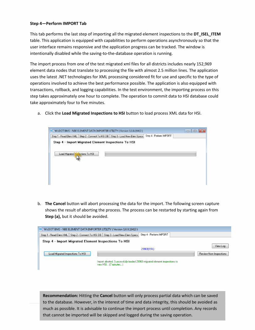
Step 4—Perform IMPORT Tab
This tab performs the last step of importing all the migrated element inspections to the DT_ISEL_ITEM
table. This application is equipped with capabilities to perform operations asynchronously so that the
user interface remains responsive and the application progress can be tracked. The window is
intentionally disabled while the saving-to-the-database operation is running.
The import process from one of the test migrated xml files for all districts includes nearly 152,969
element data nodes that translate to processing the file with almost 2.5 million lines. The application
uses the latest .NET technologies for XML processing considered fit for use and specific to the type of
operations involved to achieve the best performance possible. The application is also equipped with
transactions, rollback, and logging capabilities. In the test environment, the importing process on this
step takes approximately one hour to complete. The operation to commit data to HSI database could
take approximately four to five minutes.
a. Click the Load Migrated Inspections to HSI button to load process XML data for HSI.
b. The Cancel button will abort processing the data for the import. The following screen capture
shows the result of aborting the process. The process can be restarted by starting again from
Step (a), but it should be avoided.
Recommendation: Hitting the Cancel button will only process partial data which can be saved
to the database. However, in the interest of time and data integrity, this should be avoided as
much as possible. It is advisable to continue the import process until completion. Any records
that cannot be imported will be skipped and logged during the saving operation.

36 | P a g e
c. The following screen capture shows how the continuation of the import process is monitored.
d. Click the View Log button to review any errors or omissions.
e. Upon 100% completion of the process, click the Review New Inspections button to view the
new data in grid table format. The data will not be saved until the Save to Database button is
clicked.

37 | P a g e
f. Click the Save to Database button to save new imported element inspections data to the HSI
database.

38 | P a g e
g. Close the application by clicking the X button in the top right corner of the window. Optionally,
the user can go to the Step 2 tab and click the Disconnect button to close the database
connection.

39 | P a g e
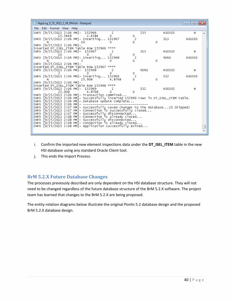
h. Navigate to the installation directory, and drill down to the folder with installation files. There
are two folders created named AppLog and Reports. The user can review log files under these
folders for error, warning, and information messages.
40 | P a g e
i. Confirm the imported new element inspections data under the DT_ISEL_ITEM table in the new
HSI database using any standard Oracle Client tool.
j. This ends the Import Process.
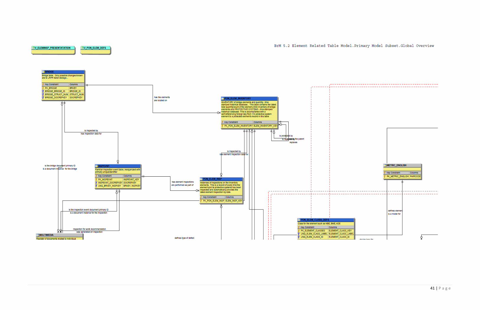
BrM 5.2.X Future Database Changes The processes previously described are only dependent on the HSI database structure. They will not
need to be changed regardless of the future database structure of the BrM 5.2.X software. The project
team has learned that changes to the BrM 5.2.X are being proposed.
The entity-relation diagrams below illustrate the original Pontis 5.2 database design and the proposed
BrM 5.2.X database design.
41 | P a g e

42 | P a g e
Recommendations As previously mentioned, the following recommendations are intended to place WisDOT in a strategic
position to export HSI information to forecast bridge needs and prioritize bridge preservation and
replacement work using the BrM 5.2.X software to be released in 2015.
Condition State Language
The Migrator does not include the capability of inserting the condition state language for the NBEs and
BMEs. It is recommended to create a custom version of the database created for the 2013 AASHTO
Guide for Bridge Element Inspection with the condition state language for the WisDOT ADEs condition
state language and import the condition state language for all elements into the HSI database.
Export/Import to BrM 5.2.3
After the BrM 5.2.3 database is defined, an application similar to the one developed to import the XML
data needs to be developed. The application would export the HSI data for analysis in BrM 5.2.3 and
seamlessly import it into BrM 5.2.3 for analysis.
Annual Report to FHWA
After the FHWA publishes the XML schema for the annual report, the developed export/import
application can be altered to include a plug-in to develop the future annual reports required by the
FHWA.

43 | P a g e
Appendix A—Literature Review Title Author Date Source/URL
AASHTO Manual for Bridge Element Inspection
AASHTO June 2013 AASHTO
Pontis 5.1.4 Database Design Changes
Bentley and Allen Marshall June 2013 AASHTO
Pontis 5.1.3 Release Notes Bentley May 2013 AASHTO
HSI Schema WisDOT December 2012 Wisconsin DOT
Development of Element Repair Costs and Estimated Life Expectancy for Bridge Maintenance
CTC & Associates October 2011 http://wisdotresearch.wi.gov/wp-content/uploads/tlselementrepaircosts-10-7-11_revised-2.pdf
AASHTO Guide Manual for Bridge Element Inspection
AASHTO January 2011 AASHTO
Pontis 5.2 Design Document Michael Baker Jr., Inc. and Paul Thompson August 2010 AASHTO
Sensitivity Analysis of Bridge Health Index to Element Failure Costs and Conditions
Teresa M. Adams and Myungook Kang November 2009 Midwest Regional Transportation Center – University of Wisconsin at Madison
Element Unit and Failure Costs and Functional Improvement Costs for Use in the MN/DOT Pontis Bridge Management System
Teresa M. Adams and Emil Juni November 2003 Minnesota DOT
Bridge Life-Cycle Cost Analysis Hugh Hawk June 2003 NCHRP Report 483
WisDOT Bridge Inspection Pocket Manual
WisDOT February 2002 Wisconsin DOT
Establishing MR&R Costs for a Network-Level Bridge Management System
Teresa M. Adams and Joseph F. Barut January 1998 Transportation Research Record 1642
Sensitivity of Network-Level BMS MR&R Policies to Variations in Cost, Transition Probability, and Discount Factor
Teresa M. Adams and P. Robert Sianipar January 1998 Transportation Research Record 1643