development and impact of software solutions - notes
TRANSCRIPT

Page 1 of 66
Development and
Impact of Software
Solutions - Notes

Page 2 of 66
Contents • Social & Ethical Issues ........................................................................................................... 3
➢ The Impact of Software ..................................................................................................... 3
o Public issues, including: ................................................................................................. 3
➢ Rights and Responsibilities of Software Developers ........................................................... 4
➢ Software Piracy and Copyright .......................................................................................... 5
➢ Use of Networks ............................................................................................................... 6
➢ The Software Market ........................................................................................................ 7
o Maintaining market position ......................................................................................... 7
o The Effect on the Marketplace ....................................................................................... 7
o Impact of New Developers & Software Products ............................................................. 7
➢ Legal Implications ............................................................................................................. 7
o National Legal Action Resulting from Software Development ......................................... 7
o International Legal Action Resulting from Software Development .................................. 7
• Application of Software Development Approaches ................................................................ 8
➢ Software Development Approaches .................................................................................. 8
o Approaches Used in Commercial Systems ....................................................................... 8
o Application of CASE TOOLS .......................................................................................... 11
o Methods of Implementation ........................................................................................ 11
o Employment Trends in Software Development ............................................................. 13
o Trends in Software Development ................................................................................. 14
Page 3 of 66
• Social & Ethical Issues
➢ The Impact of Software
o Public issues, including: ❖ The Year 2000 Problem
▪ Early computers had limited memory & RAM was expensive.
To save memory, programmers developing operating
systems reduced the storage of dates to a 2-digit integer
reducing storage needs by half. As the year 2000
approached, there was great concern about what would
happen to software that governments, banks & large
businesses depended on. Large amounts of money were
spent on changing the dates to a 4-digit format.
❖ Computer Viruses
▪ A virus is a program that alters the functionality of a
computer without the permission of the user. Viruses are a
far larger issue than the Y2k bug due to their persistent &
developing nature. Both software developers & end user
have a responsibility to combat viruses. Install & maintain a
reliable AV program that is kept up to date with the latest
patches.
❖ Reliance on Software
▪ As shown by the Y2k bug, programmers need to consider all
aspects of the software they develop particularly the needs
in the future. Software reliability becomes crucial when
society relies heavily on software for many of its basic
services.
▪ Many day to day aspects of our lives rely on software in
order to operate.
▪ Examples include:
- Motorised transport
- Electricity supply
- Operation of government authorities
❖ Social Networking
▪ A social network is simply a group of people who associate
with each other. Often, we have a variety of social networks
based on some common association. For instance, we have
social networks built around family, another for friends, one
for work & maybe some for special interests such as sports
or hobbies.

Page 4 of 66
❖ Cyber Security
▪ The online world of the internet includes a variety of
different dangers & security issues. All internet connected
devices have risks, this includes laptops, mobile phones &
even game consoles. Cyber safety is about minimising the
risk of such dangers, particularly for children. Although
security software & firewalls can assist in this regard, many
online issues are unable to be dealt with using software
alone. Cyber safety is about protecting yourself when
online. To be cyber safe means observing recommended
practices & procedures to protect your personal information
when using the internet.
➢ Rights and Responsibilities of Software Developers
Issue Right Responsibility
Authorship Protection of their products
against theft and modification without permission.
Acknowledge the authors and sources used in development.
Reliability
Protection of their product against operating system problems & other
hardware & programs which may make their product unusable.
Check the product works with the hardware & operating system they
specify.
Ensure the product has no runtime errors when installed & run as
directed.
Quality Codes to ensure that others develop programs that follow the same high
standard.
Use thorough testing procedures & error checking code.
Meet the user’s expectations as much as possible.
Response to Problems
Not to be harassed with trivial problems that could have been
solved by reading the documentation.
Provide troubleshooting manuals & online help.
Provide customer support.
Quick response to major or critical problems.
Make ‘bug fixes’ freely available to users.
Code of Conduct All developers follow same ethical
standard.
Adhere the standards set by the members of the organisation to
which they belong.
Viruses Protection of their products
with users, by users using updated anti-virus solutions.
Ensure that they do not distribute viruses with their products or as
part of their customer care (email).
Page 5 of 66
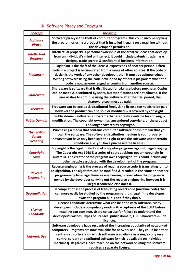
➢ Software Piracy and Copyright
Concept Meaning
Software Piracy
Software piracy is the theft of computer programs. This could involve copying the program or using a product that is installed illegally on a machine without
the developer’s permission.
Intellectual Property
Intellectual property is personal ownership of the creative ideas that develop from an individual’s mind or intellect. It could include patents, trademarks,
designs, trade secrets & confidential business information.
Plagiarism
Plagiarism is the theft of the ideas & expressions of another person. Often code in a project is accumulated from a range of other sources. If the code or
design is the work of any other developer, then it must be acknowledged. Writing software using the code developed by others is plagiarism when the
code is now acknowledged as coming from another source.
Shareware
Shareware is software that is distributed for trial use before purchase. Copies can be made & distributed by users, but modifications are not allowed. If the
user wishes to continue using the software after the trial period, the shareware cost must be paid.
Freeware Freeware can be copied & distributed freely & no license fee needs to be paid
however the product can’t be sold or modified & is covered by copyright.
Public Domain Public domain software is programs that are freely available for copying &
modification. The copyright owner has surrendered copyright, or the product is no longer covered by copyright.
Ownership Versus
Licensing
Purchasing a media that contains computer software doesn’t mean that you own the software. The software distribution medium is your property
however you have only been sold the right to use the software under certain conditions (i.e. you have purchased the license).
Copyright Laws
Copyright is the legal protection of computer programs against illegal copying. The Copyright Act 1968 & a series of court decisions govern copyright in
Australia. The creator of the program owns copyright ; this could include any other people associated with the development of the program.
Reverse Engineering
Reverse engineering is the process of reading source code & translating it into an algorithm. The algorithm can be modified & recoded in the same or another
programming language. Reverse engineering is level when the program is owned by the developer carrying out the reverse engineering however it is
illegal if someone else does it.
Decompilation Decompilation is the process of translating object code (machine code) that
can more easily be studied by the programmer. It is legal if the developer owns the program but is not if they don’t.
Licence Conditions
License conditions determine what can be done with software. Many developers include a compulsory reading & acceptance of the EULA before
installing can continue. Users no excuse for failure to understand the developer’s wishes. Types of licenses: public domain, GPL, Shareware & Site
licences .
Network Use
Software developers have recognised the increasing popularity of networked computers. Programs are now available for network use. They could be either
centralised software (in which software is available as a single copy on a central server) or distributed software (which is available on individual
machines). Regardless, each machine on the network or using the software requires a separate license.

Page 6 of 66
o There are many current day events that effect the issues of piracy and
copyright:
❖ In Indonesia in 2005 to prevent the use of pirated software which
was a major problem. To overcome this issues Microsoft charged
people in Indonesia about $1.50AU to legally own the software and
reduce the rates of piracy in the country.
o There are three types of EULA agreements:
❖ Single Use Licences – allow the purchaser to install one copy of the
software on one computer only.
❖ Multi-Use Licences – provide one copy of the software to be
distributed on a specified number of machines.
❖ Network Licences – provide the use of the software across a
network with a specific number of computers.
o Various national perspectives to software piracy and copyright laws
❖ It has been estimated that 30-40% of all software worldwide has
been illegally copied.
❖ US$11 billion is lost each year due to pirated software, about
AU$290 million in Australia alone.
o The relationship between copyright laws and software license agreements
❖ Copyright does not require any formal registration for it to apply, it
is granted automatically.
❖ Software licence agreements are used to create a binding contract
between the purchaser and the software developer, they often
contain clauses relating specifically to copyright.
➢ Use of Networks o The widespread use of networks, including the internet, has revolutionised
the development of software. The ability to collaborate & share resources
greatly improves productivity. Although network speeds continue to
improve, they still provide a bottleneck for network-based software.
Changes to the user interface in terms of how data is entered & retrieved
across the network can greatly improve response times. In addition, security
& privacy concerns must be addressed when data is transferred across the
public & insecure networks.
Page 7 of 66
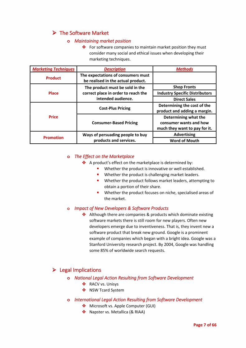
➢ The Software Market
o Maintaining market position ❖ For software companies to maintain market position they must
consider many social and ethical issues when developing their
marketing techniques.
Marketing Techniques Description Methods
Product The expectations of consumers must
be realised in the actual product.
Place The product must be sold in the
correct place in order to reach the intended audience.
Shop Fronts
Industry Specific Distributors
Direct Sales
Price
Cost-Plus Pricing Determining the cost of the
product and adding a margin.
Consumer-Based Pricing Determining what the
consumer wants and how much they want to pay for it.
Promotion Ways of persuading people to buy
products and services.
Advertising
Word of Mouth
o The Effect on the Marketplace ❖ A product’s effect on the marketplace is determined by:
▪ Whether the product is innovative or well established.
▪ Whether the product is challenging market leaders.
▪ Whether the product follows market leaders, attempting to
obtain a portion of their share.
▪ Whether the product focuses on niche, specialised areas of
the market.
o Impact of New Developers & Software Products
❖ Although there are companies & products which dominate existing
software markets there is still room for new players. Often new
developers emerge due to inventiveness. That is, they invent new a
software product that break new ground. Google is a prominent
example of companies which began with a bright idea. Google was a
Stanford University research project. By 2004, Google was handling
some 85% of worldwide search requests.
➢ Legal Implications
o National Legal Action Resulting from Software Development ❖ RACV vs. Unisys
❖ NSW Tcard System
o International Legal Action Resulting from Software Development ❖ Microsoft vs. Apple Computer (GUI)
❖ Napster vs. Metallica (& RIAA)
Page 8 of 66
• Application of Software Development Approaches
➢ Software Development Approaches
o Approaches Used in Commercial Systems ❖ Commercial software development falls into two categories:
▪ Off the shelf or retail programs (e.g. Microsoft Office) are
sold & distributed to any user who wishes to use them.
Sometimes referred to as COTS & in many cases can be
customised to suit the need or an organisation (e.g. Google
Apps for the DET).
▪ Custom programs are commissioned by a particular
organisation or individual & are written specifically to suit
the defined needs to those requiring the program.
❖ Structured Approach ▪ The structured approach follows the software development
cycle. It considers the program on a whole and takes logical
steps to arrive at the end product. The process is time
consuming and costly and necessary and suitable to tackle a
large program.
▪ Because the process is long a complex often a team of
people is required to tackle the problem. Some of the
people include system analyst, designers including software
engineers, programmers, graphic designers and consultants,
managers, trainers and users. The software analyst is the
person who is generally given control of the management of
the project and is the first level of communication between
the management and development team.
❖ Agile Approach ▪ It placed emphasis on the team developing the system
rather than following predefined structured development
processes. Agile methods remove the need for detailed
requirements & complex design documentation. Agile
methods are particularly well suited to web-based software
development & other software applications that are
modified regularly such that they evolve & are updated over
time.
❖ Prototyping ▪ It involves building a working model that is then evaluated
by users. The model is then usually modified & evaluated
further until it becomes a solution. It only involves a small
team of programmers & one or more users. The prototyping
approach is particularly useful in the development of
interactive systems & AI but not as much where complex &
large mathematical calculations are required.
▪ There are two types of prototyping used. Information
gathering prototypes are developed to gain information that
can be used in another program. The prototype is never

Page 9 of 66
intended to become the fully working solution. They are
often developed in 5GL languages & use reusable code
modules that require only linking to operate.
▪ Evolutionary prototyping becomes the full working program.
The prototype is the first step in the development of the
final product to be shown before the full program is
produced.
▪ Prototyping focuses largely on the UI including menus,
windows & IO processes. There is a great amount of user
involvement in the development process & there is reduced
amounts of documentation compared to the structure
approach, this means that the system is harder to maintain.
❖ Structured Approach ▪ The structured approach follows the software development
cycle. It considers the program on a whole and takes logical
steps to arrive at the end product. The process is time
consuming and costly and necessary and suitable to tackle a
large program.
▪ Because the process is long a complex often a team of
people is required to tackle the problem. Some of the
people include system analyst, designers including software
engineers, programmers, graphic designers and consultants,
managers, trainers and users. The software analyst is the
person who is generally given control of the management of
the project and is the first level of communication between
the management and development team.
Steps Explanation
Defining the Problem
Understand & define the problem. This is important so you know what you are solving. It is much easier & cheaper to fix mistakes here than in any other stage of
development.
Planning the Solution
Involves further understanding of the needs of the users & a choice of a method or methods to solve the problem. Data needs to be collected to provide the basis for decisions. Planning involves designing algorithms, planning a UI, data & program structures needed, scheduling the project, choosing a programming language. As
well, dataflow diagrams, IPO charts, Gantt charts, screen designs & storyboards are all likely tools that will be used there.
Building the Solution
Requires the full involvement of the team. A large & complex project is usually broken down into modules, you allow for greater efficiency, easier debugging, less
contamination of the whole project there is badly written code & you can refuse the modules that you create.
Checking the Solution
A continuous part of the development cycle. Involves using real data & may include beta testers. This is to make sure that the program meets the needs & requirements determined in the defining stage. If the project is approved, it can be implemented.
Modifying the solution
Sometimes it is necessary to make modifications after a program has been implemented so that it works more effectively. The program may need to be updated to keep abreast of hardware or software changes or may need to be
expanded to cover new tasks.

Page 10 of 66
❖ RAD ▪ The rapid applications software development is any method
of software design that uses tools to quickly generate a
program for a user. It uses existing modules & may reuse
code, CASE tools & templates. The developer is involved
directly with the user.
❖ End User Development Approach ▪ It is where the user adapts existing software tools to suit
their needs or to obtain the solution to a problem. EUD is
very informal & used for very small solutions. It is usually
created in a 4GL programming environment such as in a
spreadsheet or database.
❖ Combinations of Any of The Above ▪ Using combinations of any of the five approaches can make
it easier to develop a program. If different parts require
different approaches, then using the right approach for each
part will make the process more effective.
Types of Approaches
Advantages Disadvantages
Structured Approach
Thoroughly tested Costly
Should meet the exact requirements of users
Time consuming
Uses a range of experts Requires a range of different skills
Agile Approach
You can better adapt to change and respond faster
Demands more time and energy from everyone
You can detect and fix issues and defects faster Product lacks overall design
You don't have to worry about premature optimization
Prototyping
Relatively fast development
Many be difficult to implement as a full working program Models a larger project, thus allows
easier modification and visualisation of the end product
RAD
Fast development Many not meet exact program
requirements
Relatively cheap Many involve copyright and intellectual property of others.
(Developers must be careful not to break laws)
Uses considerable amount of existing reusable code
End User Development
Approach
Should meet exact user requirements Limited to simple project and
limitations of application programs Quick and cheap
Page 11 of 66
o Application of CASE TOOLS ❖ Software development teams often use a CASE approach to their
works. CASE tools allow the software developer to track bugs, data
model, generate documentation, reverse engineer & simulation
tools. CASE tools help the maintenance team to interact with the
development team.
❖ Software Version Control ▪ When developing a full product, there will be many versions
such as for different hardware, operating systems. The
number of versions leads to the need for version control
CASE tools can be used to take over this process. CASE tools
allow for strict control over the versioning process.
❖ Test Data Generation ▪ CASE tools can be used to generate test data for complex
programs. This can avoid time consuming manual testing or
the generation of large test data tables by a slower input
method.
❖ Production of Documentation ▪ There are a number of CASE tools available to help the
documentation process with facilities such as word
processors & drawing tools. Others can produce Gantt
charts, calendars, & other project management tools.
❖ Data Dictionary ▪ CASE tools can collect & track data types through multiple
modules & develop concise descriptions of each data type in
a program. This can be a major time advantage.
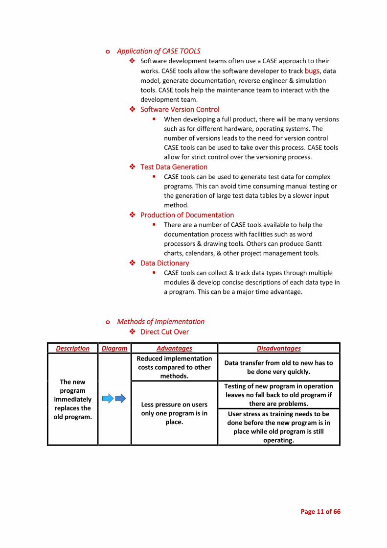
o Methods of Implementation
❖ Direct Cut Over
Description Diagram Advantages Disadvantages
The new program
immediately replaces the old program.
Reduced implementation costs compared to other
methods.
Data transfer from old to new has to be done very quickly.
Less pressure on users only one program is in
place.
Testing of new program in operation leaves no fall back to old program if
there are problems.
User stress as training needs to be done before the new program is in
place while old program is still operating.

Page 12 of 66
❖ Parallel
Description Diagram Advantages Disadvantages
The old and the new work together over
a period of time.
Two programs can be compared & any problems can
be fixed to take account of differences.
User stress as both old & new programs have to be operated
for conversion time.
Testing & fixing of problems in new program is simpler as old
program is still available for use in an emergency.
Confusion between programs if close records are not kept.
If there are large changes in operating procedures between the old & new program there
can be problems for users.
More expensive than other methods due to dual costs.
❖ Phased
Description Diagram Advantages Disadvantages
One or more tasks of the new program are
gradually implemented until the new program
takes over all tasks of the old program.
Each task can be individually tested as
it is implemented.
Difficult for users to separate the old &
the new programs & operate different
tasks in each system.
Training users is simpler as only one new task has to be
learnt.
Longer time frame leads to high
implementation costs.
❖ Pilot
Description Diagram Advantages Disadvantages
One section of the organisation uses the
new program & all other sections continue with the old program until a decision is made to put the new program into place across the whole
system.
Risk is confined to one section of an organisation.
Large organisations usually use this
method particularly throughout
multiple sites doing the same thing such
as one bank amount a series of
branches.
Testing & fixing of problems in the new program is simpler as the old program is still available for use in other parts of the organisation.

Page 13 of 66
o Employment Trends in Software Development
❖ Outsourcing ▪ Outsourcing: the process where a company needing
software services hires an outside organisation to handle all
or part of these services.
▪ This could include department, implementation, &
maintenance. Outsourcing is an effective use of scare
technological assets & cost savings due to economies of
scale however some outsourcing companies may not
understand the ethos of the company employing it & the
organisation may feel as if it is losing control of the system.
❖ Popular Approaches ▪ Increasing facilities for EUD.
▪ The availability of editors to allow non-programmers to
generate simple programs such as WYSIWYG editors.
▪ Greater distribution of code libraries.
▪ Authoring languages that guide the developer through the
steps of creating programs including mark-up languages.
▪ Increasing use of multimedia in programs.
❖ Popular Languages ▪ 4GL & 5GL languages are increasingly becoming human
centred to allow non-programmers to develop customised
software. SGL is a very powerful language but is limited to
the domain of databases. It can be used to someone who is
relatively inexperienced to create powerful database
structures.
▪ Most of the popular languages have the same basic
capabilities such as syntax, constants, variables, &
operators.
❖ Employment Trends
▪ Technology has been a growth area in employment over
the last decade & there are still large numbers of jobs in the
field despite a recent slowdown. There are increasingly high
educational requirements for those entering the industry.
❖ Contract Programmers ▪ The nature of employment in the software development
area is changing. Many positions of employment are short-
term contracts to write particular software products. It is
common for analysts & programmers to change employer
often as they seek new contracts. Contracts can be with
companies that are writing software for their own, internal
use or with software development companies who are
writing software for external customers.
Page 14 of 66
o Trends in Software Development
❖ Environment in which Developers Work
▪ Networks of computers, & in particular the Internet, have
created a new & growing environment for software
development. Developers from across the globe can
collaborate on software projects. Many popular open source
projects have contributors from a wide range of countries.
Often these developers never meet in person & may not
even speak the same language. Managing & combining the
contributions from a wide variety of contributors would be
impossible without suitable CASE tools.
❖ Changing Nature of Applications ▪ Recently the nature of software applications has undergone
rapid change. In the recent past most software developers
where writing applications for desktop computers or for
servers. The recent changes are largely due to the
widespread public acceptance & use of the internet &
mobile devices. Software developers need to continually
update their skills to take account of public demand for
internet connected software applications.
Page 15 of 66
Software
Development Cycle
Notes

Page 16 of 66
Contents • Defining & Understanding the Problem ............................................................................... 19
➢ Defining the Problem ...................................................................................................... 19
o Identifying the Problem ............................................................................................... 19
o Determining the Feasibility of the Solution ................................................................... 19
➢ Design Specifications....................................................................................................... 20
o Data Types .................................................................................................................. 20
o Data Structures ........................................................................................................... 20
o Data Validation ........................................................................................................... 20
o Algorithms .................................................................................................................. 21
o The User’s Perspective ................................................................................................. 21
➢ System Documentation ................................................................................................... 22
o Quality Assurance ....................................................................................................... 22
o Modelling ................................................................................................................... 22
➢ Communication Issues Between Client & Developer ........................................................ 25
o The Need to Empower the User .................................................................................... 25
o The Need to Acknowledge the User’s Perspective ......................................................... 25
o Enabling & Accepting Feedback ................................................................................... 25
• Planning & Designing Software Solutions ............................................................................ 26
➢ Standard Algorithms ....................................................................................................... 26
o Finding Maximum & Minimum Values in Arrays ........................................................... 26
o Processing Strings ....................................................................................................... 26
o Generating a Set of Unique Random Numbers.............................................................. 27
o Processing of Sequential Files ...................................................................................... 27
o Processing of Relative Files .......................................................................................... 28
o Searches & Sorts.......................................................................................................... 28
➢ Custom-Designed Logic Used in Software Solutions ......................................................... 30
o Requirements to Generate These ................................................................................. 30
o Customised Off-the-Shelf Packages .............................................................................. 30
➢ Records .......................................................................................................................... 31
o Using Records ............................................................................................................. 31
o Nested Records ........................................................................................................... 31
o Examples using Records ............................................................................................... 31
➢ Database Terminology .................................................................................................... 32
➢ OOP Terminology ............................................................................................................ 32

Page 17 of 66
➢ Collections ...................................................................................................................... 33
➢ Defining the Function ...................................................................................................... 33
➢ Standard Modules Used in Software Solutions ................................................................. 34
o Requirements for Generating a Module or Subroutine for Re-use.................................. 34
o Issues associated with Reusable Modules or Subroutines .............................................. 34
➢ Documentation of the overall software solution .............................................................. 34
o Tools for Representing a Complex Software Solution .................................................... 34
➢ Interface Design in Software Solutions ............................................................................ 35
➢ Factors to Be Considered When Selecting the Technology ................................................ 35
• Implementation of Software Solution ................................................................................. 36
➢ Implementation of the Design Using an Appropriate Language ........................................ 36
o The Design of Individual Screens .................................................................................. 36
➢ Language Syntax Required for Software Solutions ........................................................... 37
o BNF ............................................................................................................................. 39
o EBNF ........................................................................................................................... 39
➢ Translational to Machine Code from Source Code ............................................................ 40
o Translation Methods ................................................................................................... 40
o Steps in Translation Methods....................................................................................... 41
➢ The Role of Machine Code in the Execution of a Program ................................................. 42
o Machine Code & CPU Operation .................................................................................. 42
➢ Techniques Used in Developing Well-Written Code .......................................................... 43
o Structured Approach to Complex Solution .................................................................... 43
o The Process of Detecting & Correcting Errors ................................................................ 44
o Use of Software Debugging Tools ................................................................................ 44
➢ Documentation of a Software Solution ............................................................................ 45
o Forms of Documentation ............................................................................................. 45
o Use of Application Software to Assist in Documentation ............................................... 46
➢ Hardware Environment to Enable Implementation of The Software Solution .................... 46
o Minimum Configuration .............................................................................................. 46
o Possible Additional Hardware ...................................................................................... 46
o Appropriate Drivers or Extensions ................................................................................ 46
➢ Emerging Technologies.................................................................................................... 47
o Hardware .................................................................................................................... 47
o Software ..................................................................................................................... 47
o Their Effect on: ............................................................................................................ 47
Page 18 of 66
• Testing & Evaluating of Software Solutions ......................................................................... 48
➢ Testing the Software Solution ......................................................................................... 48
o Comparison of the Solution with the Original Design Specification ................................ 48
o Generating Relevant Test Data for Complex Solutions .................................................. 48
o Levels of Testing .......................................................................................................... 48
o The Use of Live Test Data to Test the Complete Solution ............................................... 48
➢ Reporting on the Testing Process ..................................................................................... 49
o Documentation of the Test Data & the Output Produced .............................................. 49
o Communication with Consumers .................................................................................. 49
➢ Evaluating the Software Solution..................................................................................... 49
o Benchmarking ............................................................................................................. 49
o Quality Assurance ....................................................................................................... 49
o Post Implementation Review ....................................................................................... 49
• Maintaining Software Solutions .......................................................................................... 50
➢ Modifying Code to Meet Changed Requirements ............................................................. 50
o Identification of the Reasons for Change in Code, Macros ............................................. 50
o Location of Section to be Altered ................................................................................. 50
o Determining Changes to be Made ................................................................................ 50
o Implementing & Testing Solution ................................................................................. 50
➢ Documenting Changes .................................................................................................... 50
o Source Code, Macro & Script Documentation ............................................................... 50
o Modification of Associated Hard Copy Documentation & Online Help ........................... 50
o Use of CASE Tools to Monitor Changes & Versions ........................................................ 50

Page 19 of 66
• Defining & Understanding the Problem
➢ Defining the Problem
o Identifying the Problem ❖ Needs
▪ It is the programmer’s job to determine how to solve a problem or
meet the need of a user. Requirements definition: clear statement
of the requirements of the system being developed.
❖ Objectives
▪ The short & long term aims & plans for the software being
developed.
❖ Boundaries
▪ The boundary is the limit to a system such as the scope of a
project. It is also important to consider any constraints.
o Determining the Feasibility of the Solution ❖ Is it Worth Solving?
▪ An investigation into the problem will allow the systems analyst to
decide if the problem can be solved or if an alternative route can
be taken.
❖ Technical
▪ What hardware and software are currently being used? Can this
hardware be used with the software to build a workable solution?
How much will it cost to upgrade hardware? Is the hardware
needed acquirable?
❖ Economic/Budgetary
▪ Is the solution to the problem affordable? A cost/benefit analysis
of the solution will be used to determine initial & recurring costs
as well as benefits to the consumer.
❖ Scheduling
▪ The time frame in which a solution must be developed. Is the
solution achievable within the set time frame?
❖ Operational
▪ Whether a solution will be useable by the target customers. Users
must be able to effectively operate the system. Costs of training
users must be factored into the cost/benefit study.
❖ Legal
▪ Does the software comply to legal standards? For example, does it
calculate GST correctly? Does it acknowledge other author’s their
code is used?
❖ Social & Ethical Considerations
▪ Will the new system impact on the jobs of current employees?
Will the software be open to misuse? Will features that provide
wider accessibility need to be implemented?
Page 20 of 66
❖ Possible Alternatives
▪ Once determining feasibility, a decision must be made as to
whether the solution is to be implemented. If it is not feasible, the
software developer may choose to explore alternative solutions to
the problem.
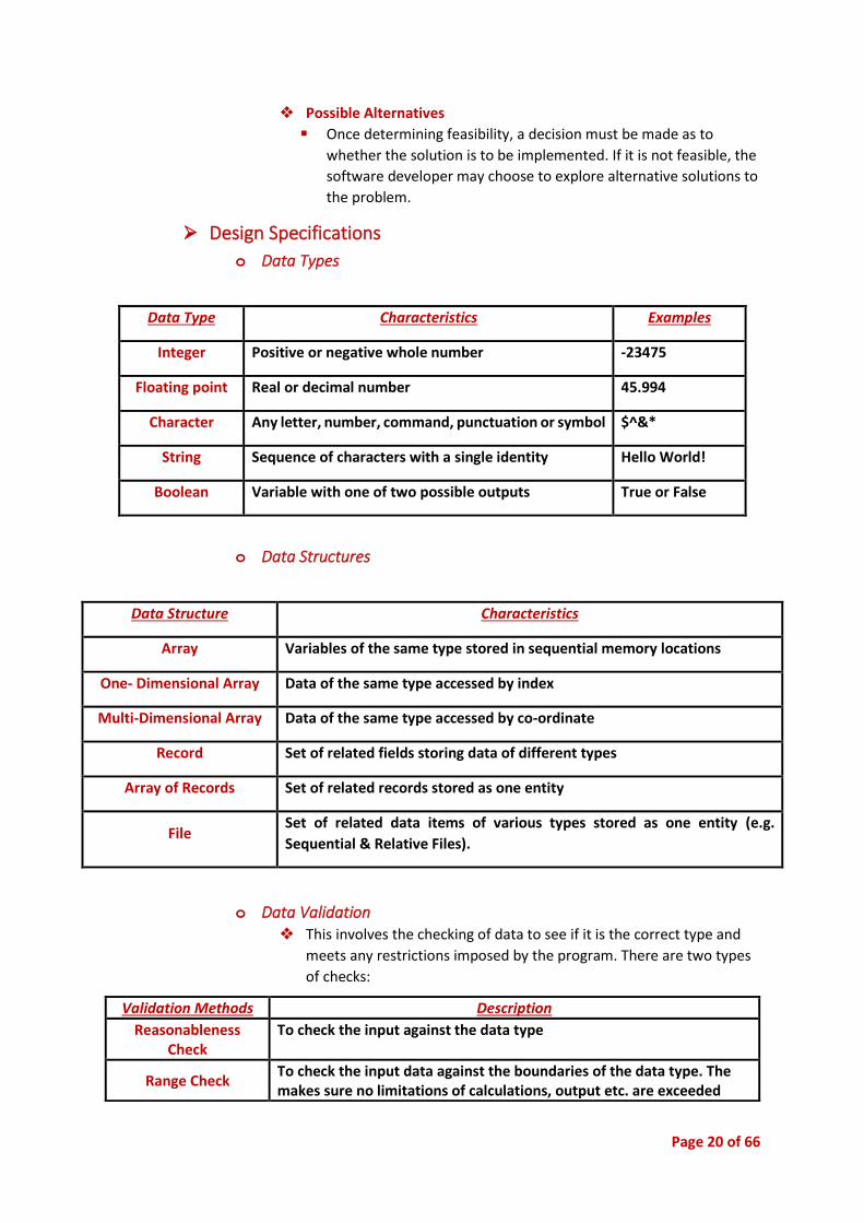
➢ Design Specifications
o Data Types
Data Type Characteristics Examples
Integer Positive or negative whole number -23475
Floating point Real or decimal number 45.994
Character Any letter, number, command, punctuation or symbol $^&*
String Sequence of characters with a single identity Hello World!
Boolean Variable with one of two possible outputs True or False
o Data Structures
Data Structure Characteristics
Array Variables of the same type stored in sequential memory locations
One- Dimensional Array Data of the same type accessed by index
Multi-Dimensional Array Data of the same type accessed by co-ordinate
Record Set of related fields storing data of different types
Array of Records Set of related records stored as one entity
File Set of related data items of various types stored as one entity (e.g.
Sequential & Relative Files).
o Data Validation ❖ This involves the checking of data to see if it is the correct type and
meets any restrictions imposed by the program. There are two types
of checks:
Validation Methods Description
Reasonableness Check
To check the input against the data type
Range Check To check the input data against the boundaries of the data type. The makes sure no limitations of calculations, output etc. are exceeded

Page 21 of 66
o Algorithms
Binary Selection Multi-Way Selection
Pre-Test Loop Post-Test Loop
o The User’s Perspective ❖ The important aspects to the user must be considered in the design
specification. These include:
▪ The Appearance of the Program & the Ease of Use: the user
interface must be ‘user friendly’ containing drop down menus,
clickable icons and keyboard shortcuts. The interface must be
intuitive and have simple navigation
▪ The Programs Functionality: this refers to the programs ability to
carry out the required tasks. This should be designed such that the
tasks are carried out in the easiest and simplest way
▪ The Programs Scope: this refers to the boundaries of the program
and the range of tasks carried out. The users would want to know
if future needs and any maintenance requirements can be done so
in an easy and convenient way.

Page 22 of 66
➢ System Documentation
o Quality Assurance ❖ Efficiency
❖ Integrity
❖ Reliability
❖ Usability
❖ Accuracy
❖ Maintainability
❖ Testability
❖ Re-usability
o Modelling ❖ IPO Charts
▪ An IPO chart describes the system in terms of its input data,
output data & the processes that are performed on the inputs
transfer them into the outputs.
Input Process Output
Number of elements Creation of an empty array with entered number of elements
Empty array with entered number of elements
❖ Context Diagrams
▪ Context Diagrams are used to represent entire information
systems. This system shown as a single process along with the
input & output (external entities) to the system.
Names Symbols Description
Process
Circles are used to represent processes. Processes are actions taking place to transform inputs to outputs. In a context diagram, a system is represented by a single, labelled circle. In a data flow diagram, multiple circles represent multiple processes within the system.
Data Flow
Curved lines represent data flows between processes, data stores & external entities. Data flows should be named to identify the piece of data.
External Entity
Boxes are used to represent external entities. These are any item, person or organisation sitting outside the systems that provide data to the system or receives data from the system.
The below is only used for Data Flow Diagrams
Data Store
An open-ended rectangle is used to represent a data store. Data stores include electronic or non-computer-based stores of data. They should be named with a logical name.

Page 23 of 66
❖ Data Flow Diagrams
▪ Data flow diagrams represent the flow of data into & out of the
system in terms of the processes used. A data flow diagram
provides more detail at a lower level a context diagram. Contains
processes, data flows, external entities, & data stores.
❖ Storyboard
▪ Storyboards give a general overview of a program. They are used
to document the screens used in a system & the flow between
them. They are suited to applications with a large number of
screens of information which link to other screens. Storyboards
can also be useful in planning the flow of information between
modules.
❖ Data Dictionary
▪ Data dictionaries are a set of information describing the contents,
format, and structure of a database and the relationship between
its elements, used to control access to and manipulation of the
database.
Field Name Data Type
Field Size Description Examples
AmountInWords String 255 Returns the currency amount in words
Six thousand, two hundred and fifty and forty-five cents.
Amount Floating Point
4 Input parameter. 6250.45
TempDigit Integer 2 Stores each digit as it is extracts from Amount.
6
DigitWord(19) Array (String)
10*20 The word associated with each digit.
DigitWord(5)=”five”
❖ Desk Check
Position Pointer [elements] Point + 1 [elements] Flag Array
1 0 [4, -35, 37, -3, 24, 17]
1 4 -35 1 [-35, 4, 37, -3, 24, 17]
2 0 [-35, 4, 37, -3, 24, 17]
3 37 -3 1 [-35, 4, -3, 37, 24, 17]
4 37 24 1 [-35, 4, -3, 24, 37, 17]
5 37 17 1 [-35, 4, -3, 24, 17, 37]
1 0 [-35, 4, -3, 24, 17, 37]
2 4 -3 1 [-35, -3, 4, 24, 17, 37]
3 0 [-35, 3, 4, 24, 17, 37]
4 24 17 1 [-35, 3, 4, 17, 24, 37]
5 0 [-35, 3, 4, 17, 24, 37]
1 0 [-35, 3, 4, 17, 24, 37]
2 0 [-35, 3, 4, 17, 24, 37]
3 0 [-35, 3, 4, 17, 24, 37]
4 0 [-35, 3, 4, 17, 24, 37]
5 0 [-35, 3, 4, 17, 24, 37]
Page 24 of 66
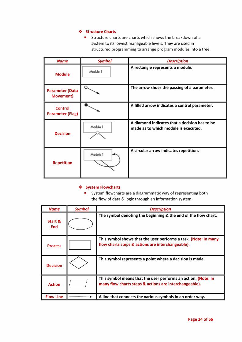
❖ Structure Charts
▪ Structure charts are charts which shows the breakdown of a
system to its lowest manageable levels. They are used in
structured programming to arrange program modules into a tree.
❖ System Flowcharts
▪ System flowcharts are a diagrammatic way of representing both
the flow of data & logic through an information system.
Name Symbol Description
Start & End
The symbol denoting the beginning & the end of the flow chart.
Process
This symbol shows that the user performs a task. (Note: In many flow charts steps & actions are interchangeable).
Decision
This symbol represents a point where a decision is made.
Action
This symbol means that the user performs an action. (Note: In many flow charts steps & actions are interchangeable).
Flow Line A line that connects the various symbols in an order way.
Name Symbol Description
Module
A rectangle represents a module.
Parameter (Data Movement)
The arrow shoes the passing of a parameter.
Control Parameter (Flag)
A filled arrow indicates a control parameter.
Decision
A diamond indicates that a decision has to be made as to which module is executed.
Repetition
A circular arrow indicates repetition.

Page 25 of 66
➢ Communication Issues Between Client & Developer
o The Need to Empower the User ❖ The user needs to be consulted on a regular basis so that the user feels
‘in control’ of the software development. Ideas from the user should
be included in the software, or where ideas have been left out,
reasoning for this should be explained to the user. Further users should
be provided with a choice of functional option within the final product.
Satisfaction with the end design is decided by the user.
o The Need to Acknowledge the User’s Perspective ❖ The user does not need to know the technical information about the
software; however, they will be the ones using the software.
Therefore, specific requirements set by the users that will make the
program function better for them should be taken into consideration
o Enabling & Accepting Feedback ❖ Feedback should be encouraged, as it is cheaper and easier to solve
problems early on in the development cycle. Prototypes are effective
ways of noting user reaction and help clarify development needs.

Page 26 of 66
• Planning & Designing Software Solutions
➢ Standard Algorithms
o Finding Maximum & Minimum Values in Arrays
o Processing Strings ❖ Extracting
The original string is not altered in the process, instead
a second string is created using a section of the
original.
❖ Inserting
▪ A new string is inserted into a specific place in the original string.
❖ Deleting
▪ Removing a section of a string.

Page 27 of 66
o Generating a Set of Unique Random Numbers ❖ Many games utilise random numbers in a variety of ways. Obvious
examples include shuffling cards, rolling dice & selecting lotto number,
however they are also used in various less obvious ways such as
moving background characters or creating realistic water or cloud
movement.
❖ Let us work through the process of creating & refining a function which
will generate a set of unique random integers. The function will accept
three parameters namely, the minimum value & the maximum value to
be generated, & the number of unique values to generate. The
function will return an array containing the generated random integer
values. For instance, the call randomArray(3, 6, 2) would return an
array containing 2 different numbers from the set of possible numbers
3, 4, 5, 6.
❖ Our first attempt uses the following logic:
1. Generate a random number, say r.
2. Search through the array of random numbers already
generated looking for r.
3. If we find r in the array,
then go back to step 1 to
try again.
4. If we don’t find r then
add r to the array of
random numbers.
5. Repeat steps 1 to 4 above
until we have the
required number of
random numbers.
o Processing of Sequential Files ❖ Sentinel Value
▪ A sentinel value is a special value that is used to terminate a loop.
The sentinel value typically is chosen so as to not be a legitimate
data value that the loop will encounter and attempt to perform
with. For example, in a loop algorithm that computes non-
negative integers, the value "-1" can be set as the sentinel value as
the computation will never encounter that value as a legitimate
processing output.
▪ Also referred to as a flag value or a signal value.
❖ Priming Read
▪ It is the input operation that takes place just before an input
validation loop. The purpose of the priming read is to get the first
input value.
❖ Open for Input, Output or Append
❖ Close
❖ Appending Records
Page 28 of 66
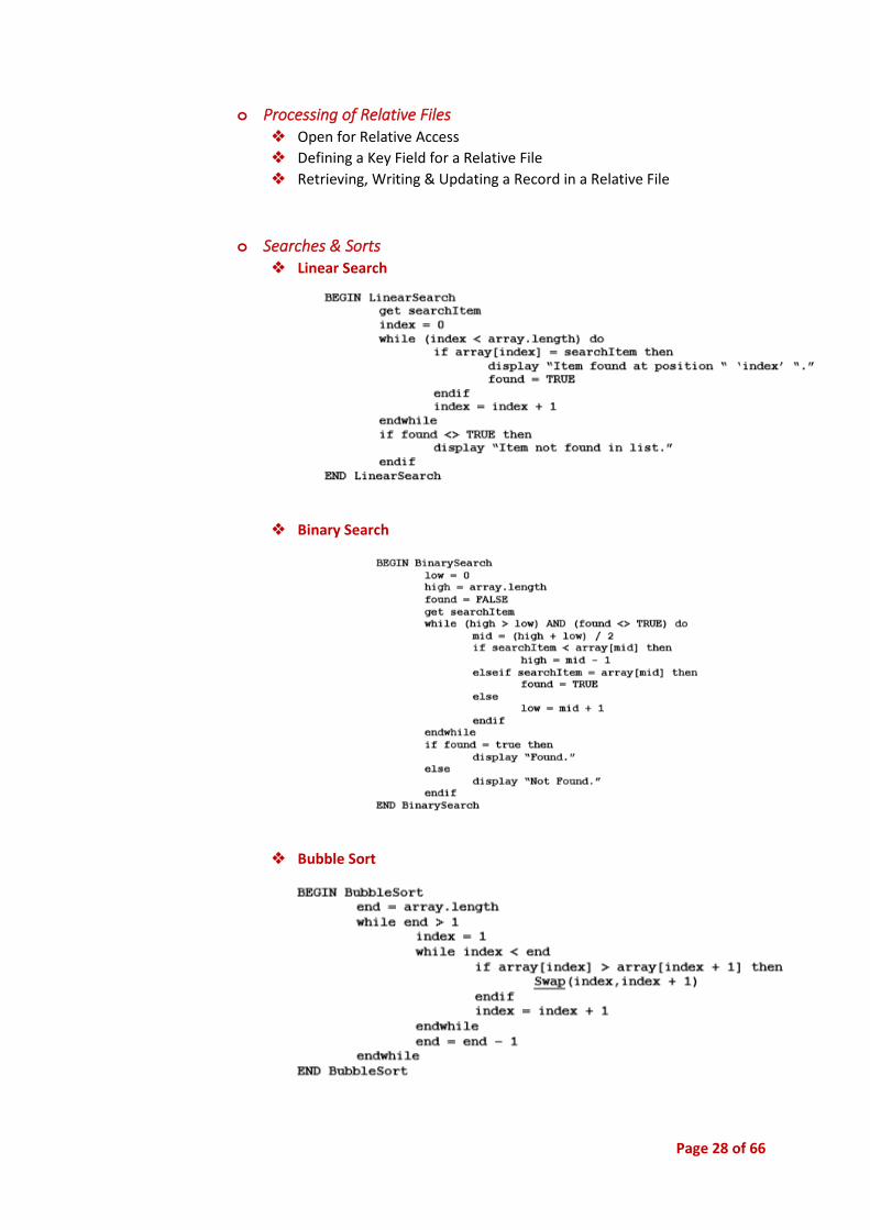
o Processing of Relative Files ❖ Open for Relative Access
❖ Defining a Key Field for a Relative File
❖ Retrieving, Writing & Updating a Record in a Relative File
o Searches & Sorts ❖ Linear Search
❖ Binary Search
❖ Bubble Sort

Page 29 of 66
❖ Insertion Sort
❖ Selection Sort
Searches & Sorts Properties
Linear Search
Simplest searching algorithm.
Highly inefficient, especially with large arrays.
Array can be sorted or unsorted.
Compare search item with every other item in the array until either the item is found, or the end of the list is reached.
Binary Search
Very efficient search even with large arrays as the array is already sorted.
Continually cuts the array in half until the item is found or it is determined the item is not in the list.
Bubble Sort
Each element is compared with the element next to it and if they are out of order they are swapped.
Elements end up “bubbling” towards their correct location in the array.
Insertion Sort Scanning forward until an out of place item is found and then scan backward until you find its correct location and insert it there.
Selection Sort Scanning through the array to find the largest unsorted item and then selecting it and swapping it with the item in its correct position.
Page 30 of 66
➢ Custom-Designed Logic Used in Software Solutions
o Requirements to Generate These ❖ Identification of Inputs, Processes & Outputs
▪ Software developer must describe the data, its format and its
method of input or output.
▪ IPO diagrams are useful to show the relationship between inputs,
the processes carried out and the outputs
❖ Representation as an Algorithm
▪ Algorithms clearly describe the steps involved in solving a
problem.
▪ Writing one helps understand the logic of a problem.
❖ Definition of Required Data Structures
▪ Along with algorithms, programmers must also determine the
most appropriate data structures for solving a problem.
▪ A data dictionary may be used to determine all the information
that is to be stored and determine a suitable data type.
❖ Use of Data Structures
▪ Multidimensional Arrays
- Useful for storing values which are logically stored in a grid
or table.
▪ Arrays of Records
- Useful for storing a variety of different data types for a
number of items.
▪ Files (Sequential & Relative)
- A collection of data stored in a logical manner, usually on
secondary storage devices.
- Sequential files must be read or written to from start to
finish in a linear fashion (e.g. data tape).
- Relative/random files allow access of different parts of the
file in a non-sequential manner (e.g. hard drive).
❖ Use of Random Numbers
▪ Often used to allow access to unpredictable data.
▪ Usually generated as rational numbers between 0 & 1.
❖ Thorough Testing
▪ Testing must be completed at each stage of the development
cycle.
▪ If a mistake is carried through the software development cycle, it
becomes increasingly expensive to fix.
o Customised Off-the-Shelf Packages ❖ Identifying an Appropriate Package
❖ Identifying the Changes That Need to be Made
❖ Identifying How the Changes Are to be Made
Page 31 of 66
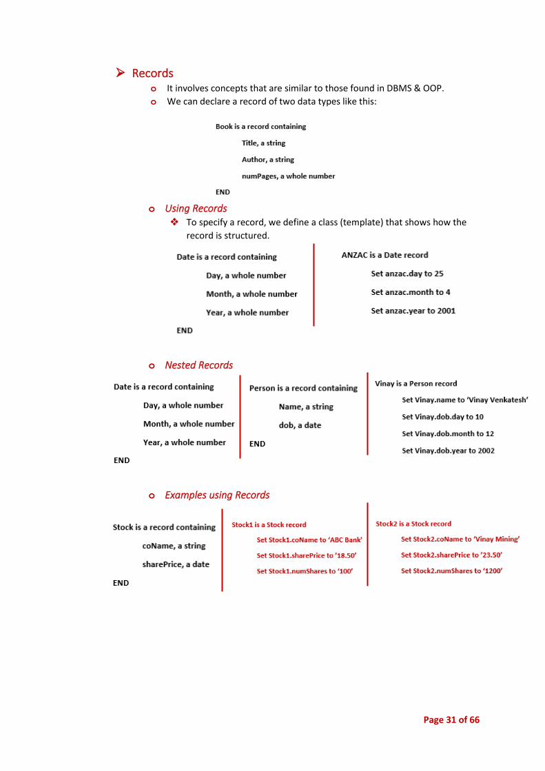
➢ Records o It involves concepts that are similar to those found in DBMS & OOP.
o We can declare a record of two data types like this:
o Using Records ❖ To specify a record, we define a class (template) that shows how the
record is structured.
o Nested Records
o Examples using Records
Page 32 of 66
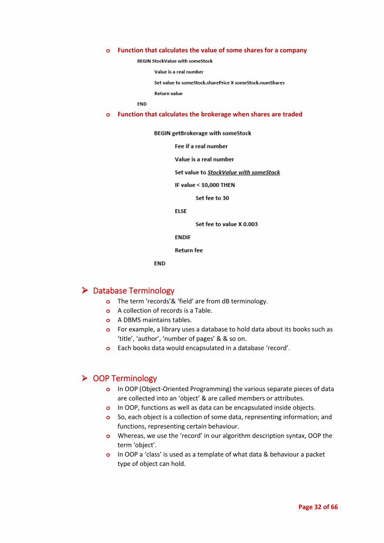
o Function that calculates the value of some shares for a company
o Function that calculates the brokerage when shares are traded
➢ Database Terminology o The term ‘records’& ‘field’ are from dB terminology.
o A collection of records is a Table.
o A DBMS maintains tables.
o For example, a library uses a database to hold data about its books such as
‘title’, ‘author’, ‘number of pages’ & & so on.
o Each books data would encapsulated in a database ‘record’.
➢ OOP Terminology o In OOP (Object-Oriented Programming) the various separate pieces of data
are collected into an ‘object’ & are called members or attributes.
o In OOP, functions as well as data can be encapsulated inside objects.
o So, each object is a collection of some data, representing information; and
functions, representing certain behaviour.
o Whereas, we use the ‘record’ in our algorithm description syntax, OOP the
term ‘object’.
o In OOP a ‘class’ is used as a template of what data & behaviour a packet
type of object can hold.
Page 33 of 66
➢ Collections o A collection refers to the storage & management of several or many
records.
o A DBMS hold a collection of records in a table & provides several standard
routines for managing the records;
❖ Adding new records
❖ Searching & retrieving records, &
❖ Changing the values stored in records
o In OOP, specific objects defined in ‘container classes’ do the same king of
work.
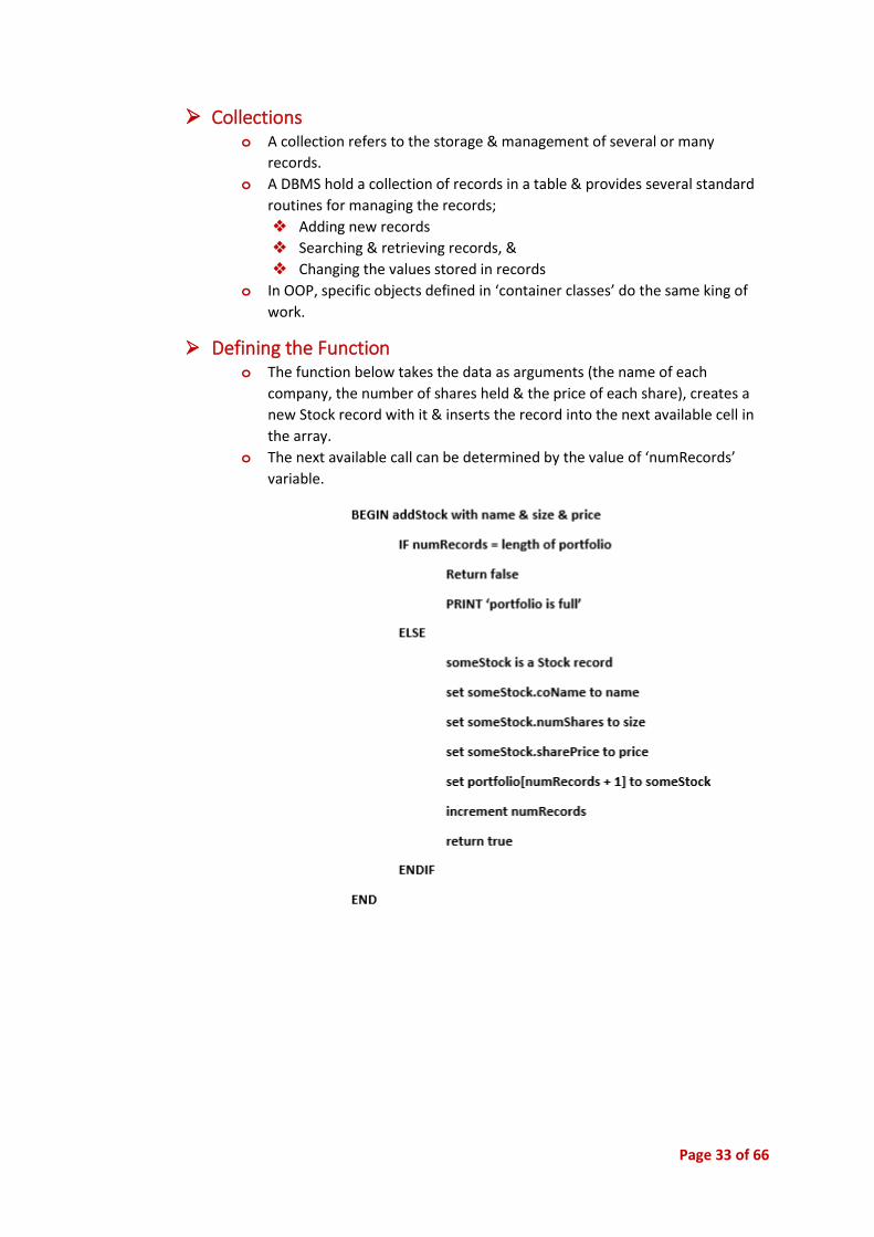
➢ Defining the Function o The function below takes the data as arguments (the name of each
company, the number of shares held & the price of each share), creates a
new Stock record with it & inserts the record into the next available cell in
the array.
o The next available call can be determined by the value of ‘numRecords’
variable.

Page 34 of 66
➢ Standard Modules Used in Software Solutions
o Requirements for Generating a Module or Subroutine for Re-use ❖ Identification of Appropriate Modules or Subroutine
▪ Best to only use modules or libraries that are necessary to perform
the required task.
▪ Using unnecessary/redundant libraries is a waste of resources.
❖ Appropriate Testing Using Drivers
▪ Best to only use modules or libraries that are necessary to perform
the required task.
▪ Using unnecessary/redundant libraries is a waste of resources.
❖ Thorough Documentation of The Routine:
▪ Author
▪ Date
▪ Purpose
▪ Order & Nature of Parameters to Be Passed
o Issues associated with Reusable Modules or Subroutines ❖ Identifying Appropriate Modules or Subroutines
❖ Considering Local & Global Variables
▪ Local variables can only be used within their own
module/subprogram.
▪ Global variables can be accessed throughout the whole program.
❖ Appropriately Using Parameters (arguments)
▪ Parameters are data items which can be passed to and from
subprograms.
➢ Documentation of the overall software solution
o Tools for Representing a Complex Software Solution ❖ Algorithms
▪ Provide a detailed description of the logic carried out in a
program.
▪ Do not indicate data manipulation.
❖ Data Flow Diagrams
▪ Useful for tracking the movement of data through a system.
▪ Graphically show the processing which occurs in a system and
indicate where data is stored.
❖ Structure Charts
▪ Method of representing the elements of a system in a hierarchical
form.
▪ Modules represented by boxes with data and controls past
between modules.
❖ System Flowcharts
▪ Graphical means of representing the logic of a computer system.
▪ Also demonstrate the source and destination of data which is used
by the system.

Page 35 of 66
❖ Data Dictionaries
- Helps the programmer understand the data that will be
used in a particular program.
- Includes the names, data types and descriptions of the data
items used.
➢ Interface Design in Software Solutions o Menus
o Command Buttons
o Tool Bars
o Text Bars
o List Boxes
o Combination Boxes
o Check Boxes
o Option or Radio Buttons
o Scroll Bars
o Grids
o Labels
o Picture or Image Boxes
➢ Factors to Be Considered When Selecting the Technology o Performance Requirements
o Benchmarking
Page 36 of 66
• Implementation of Software Solution
➢ Implementation of the Design Using an Appropriate Language
o The Design of Individual Screens ❖ Identification of Data Required
▪ Individual screens must display data.
▪ Good design will enhance the ability of the user to view or enter
data.
▪ Such screen layout techniques include:
- Appropriate use of graphics
- Positioning of text on the screen
- Alignment and justification
- Appropriate use of upper and lower case
- Colour of text and background
❖ Current Popular Approaches
▪ Early computer programs relied heavily on command line
interfaces.
▪ Graphic User Interfaces (GUIs) that use the following elements are
now usually used:
- Menus
- Windows
- Icons
- Scroll Bars
- Radio Buttons
- Dialogue Boxes
❖ Design of Help Screens
▪ Help screens should be simple, non-threatening and guide the
user in a positive manner.
▪ Context sensitive, procedural and conceptual help as well as tours
and tutorials can be used.
❖ Audience Identification
▪ Language should be clear and unambiguous.
▪ The program must use language appropriate for its target group.
❖ Consistency in Approach
▪ It is important to keep fonts, colours and placement consistent
throughout the program so that it is easier to use to for the user.
Page 37 of 66
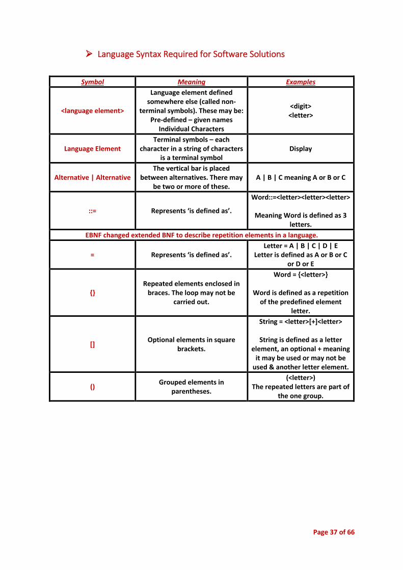
➢ Language Syntax Required for Software Solutions
Symbol Meaning Examples
<language element>
Language element defined somewhere else (called non-
terminal symbols). These may be: Pre-defined – given names
Individual Characters
<digit> <letter>
Language Element Terminal symbols – each
character in a string of characters is a terminal symbol
Display
Alternative | Alternative The vertical bar is placed
between alternatives. There may be two or more of these.
A | B | C meaning A or B or C
::= Represents ‘is defined as’.
Word::=<letter><letter><letter>
Meaning Word is defined as 3 letters.
EBNF changed extended BNF to describe repetition elements in a language.
= Represents ‘is defined as’. Letter = A | B | C | D | E
Letter is defined as A or B or C or D or E
{} Repeated elements enclosed in
braces. The loop may not be carried out.
Word = {<letter>}
Word is defined as a repetition of the predefined element
letter.
[] Optional elements in square
brackets.
String = <letter>[+]<letter>
String is defined as a letter element, an optional + meaning
it may be used or may not be used & another letter element.
() Grouped elements in
parentheses.
(<letter>) The repeated letters are part of
the one group.
Page 38 of 66
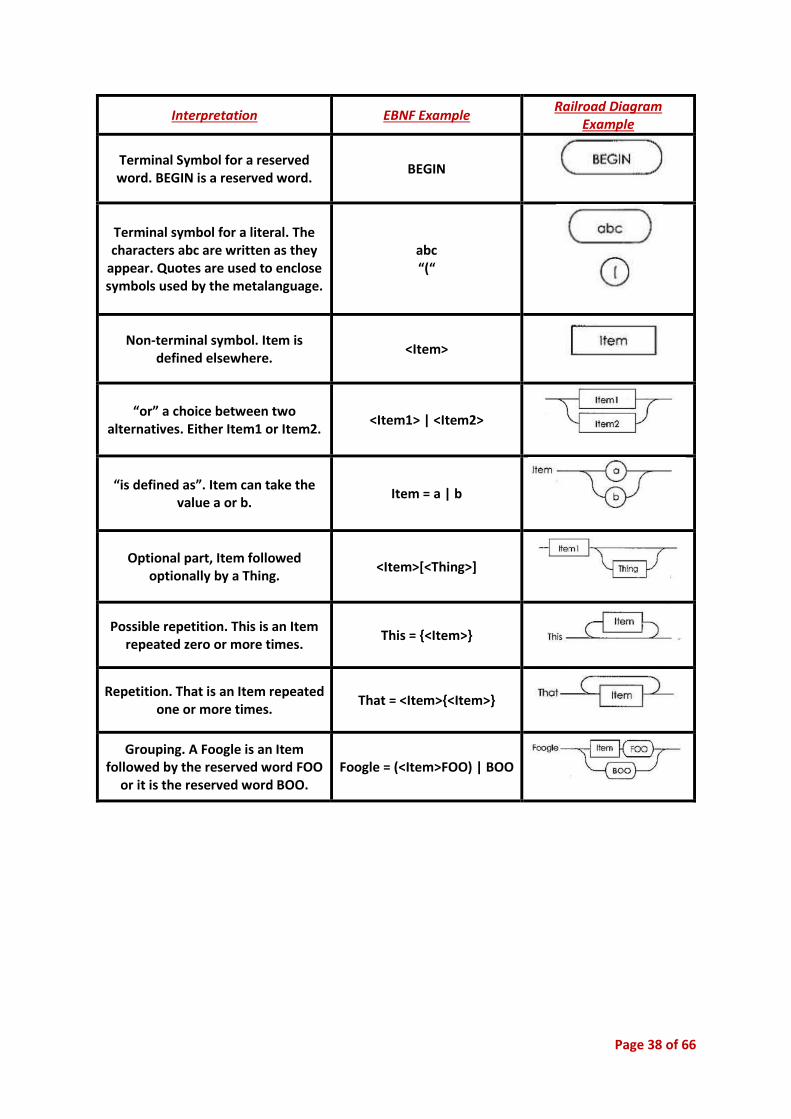
Interpretation EBNF Example Railroad Diagram
Example
Terminal Symbol for a reserved word. BEGIN is a reserved word.
BEGIN
Terminal symbol for a literal. The characters abc are written as they
appear. Quotes are used to enclose symbols used by the metalanguage.
abc “(“
Non-terminal symbol. Item is defined elsewhere.
<Item>
“or” a choice between two alternatives. Either Item1 or Item2.
<Item1> | <Item2>
“is defined as”. Item can take the value a or b.
Item = a | b
Optional part, Item followed optionally by a Thing.
<Item>[<Thing>]
Possible repetition. This is an Item repeated zero or more times.
This = {<Item>}
Repetition. That is an Item repeated one or more times.
That = <Item>{<Item>}
Grouping. A Foogle is an Item followed by the reserved word FOO
or it is the reserved word BOO. Foogle = (<Item>FOO) | BOO
Page 39 of 66
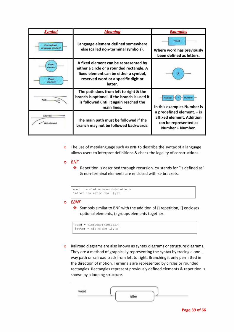
Symbol Meaning Examples
Language element defined somewhere else (called non-terminal symbols).
Where word has previously
been defined as letters.
A fixed element can be represented by either a circle or a rounded rectangle. A fixed element can be either a symbol,
reserved word or a specific digit or letter.
The path does from left to right & the branch is optional. If the branch is used it
is followed until it again reached the main lines.
In this examples Number is a predefined element. + is affixed element. Addition
can be represented as Number + Number.
The main path must be followed if the branch may not be followed backwards.
o The use of metalanguage such as BNF to describe the syntax of a language
allows users to interpret definitions & check the legality of constructions.
o BNF ❖ Repetition is described through recursion. ::= stands for “is defined as”
& non-terminal elements are enclosed with <> brackets.
o EBNF ❖ Symbols similar to BNF with the addition of {} repetition, [] encloses
optional elements, () groups elements together.
o Railroad diagrams are also known as syntax diagrams or structure diagrams.
They are a method of graphically representing the syntax by tracing a one-
way path or railroad track from left to right. Branching it only permitted in
the direction of motion. Terminals are represented by circles or rounded
rectangles. Rectangles represent previously defined elements & repetition is
shown by a looping structure.
Page 40 of 66
o Multi-Dimensional Arrays
❖ A multi-dimensional array is an array with more than one level or
dimension. For example, a 2D array, or two-dimensional array, is an
array of arrays, meaning it is a matrix of rows and columns (think of a
table). A 3D array adds another dimension, turning it into an array of
arrays of arrays.
o Arrays of Records
❖ A table is a data structure which is a collection of records. It is
commonly implemented as an array of records, ie: an array where each
of the individual elements is a record.
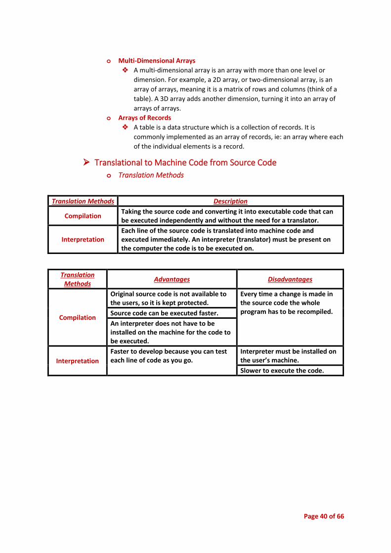
➢ Translational to Machine Code from Source Code
o Translation Methods
Translation Methods Description
Compilation Taking the source code and converting it into executable code that can be executed independently and without the need for a translator.
Interpretation Each line of the source code is translated into machine code and executed immediately. An interpreter (translator) must be present on the computer the code is to be executed on.
Translation Methods
Advantages Disadvantages
Compilation
Original source code is not available to the users, so it is kept protected.
Every time a change is made in the source code the whole program has to be recompiled. Source code can be executed faster.
An interpreter does not have to be installed on the machine for the code to be executed.
Interpretation
Faster to develop because you can test each line of code as you go.
Interpreter must be installed on the user’s machine.
Slower to execute the code.
Page 41 of 66
o Steps in Translation Methods ❖ The translation process involves a series of stages before object code is
produced. These stages and the elements of them are outlined below.
▪ Lexical Analysis
- This is the first stage and involves the reading of
the code. The code is read character by character
according to the syntax rules of the programming
language. White space is omitted
- Other elements of the code are given tokens
according to the type of characters they are;
language elements, syntax, constants, operators,
variables
- Each statement is identified and separated for the
next stage of translation
▪ Syntactical analysis
- This stage arranges the tokens in a way which can
be understood by the processor
- Parsing (the use of a parse tree) creates a
hierarchy of each section (token) of the code so
that it can be interpreted in the same way each
time
- Type checking is then carried out. Each of the data
types in a statement are passed to the translator.
Each statement is checked to make sure the
operations being performed are valid according to
the data type. Error messages are returned to
confliction occurs
- Traversing then generates the code by moving
from the top left of the parse tree down from left
to right. Each token in the tree is subsequently
converted to machine code
▪ Code Generation
- If the processes of lexical analysis & syntactical
analysis have completed without error, then the
machine code can be generated. This stage
involves converting each token or series of tokens
into their respective machine code instructions.
Because we know that the tokens are correct &
are in the correct order, no errors will be found
during code generation.
- The code generator performs the task of
conversion from tokens to object code, the code
that is executable by the computer. The generator
traverses the parse tree according to a set of strict
rules, creating appropriate machine code
whenever it gathers sufficient tokens to form a
machine command. It continues through the tree
Page 42 of 66
in this manner until all instructions have been
coded.
- The code generator is also governed by the syntax
rules used to write the source code. The code
generator used for this example starts at the top
left of the tree and moves downwards and to the
right around the tree. As it moves around the tree,
it chooses tokens from the ends of the branches,
moving left to right around the tree. This process
is known as traversing the tree.
➢ The Role of Machine Code in the Execution of a Program
o Machine Code & CPU Operation ❖ Instruction format
▪ Machine instructions need to convey a number of pieces of
information to the processor. This means that the way in which
the bits of the instruction are arranged is important. The first
few bits are used to ‘tell’ the CPU the type of instruction to be
carried out. These first bits are represented by the most
significant bits of the first instruction byte.
❖ Use of Registers & Accumulators
▪ Registers are temporary storage locations that can hold one
instruction.
▪ The accumulator is one of these registers.
❖ Use of Program Counter & Instruction Register
▪ The program counter is a register that stores the address of the
next executable instruction. It is automatically incremented
when an instruction is executed.
▪ The instruction register is the part of a CPU's control unit that
holds the instruction currently being executed or decoded. In
simple processors, each instruction to be executed is loaded into
the instruction register, which holds it while it is decoded,
prepared and ultimately executed, which can take several steps.
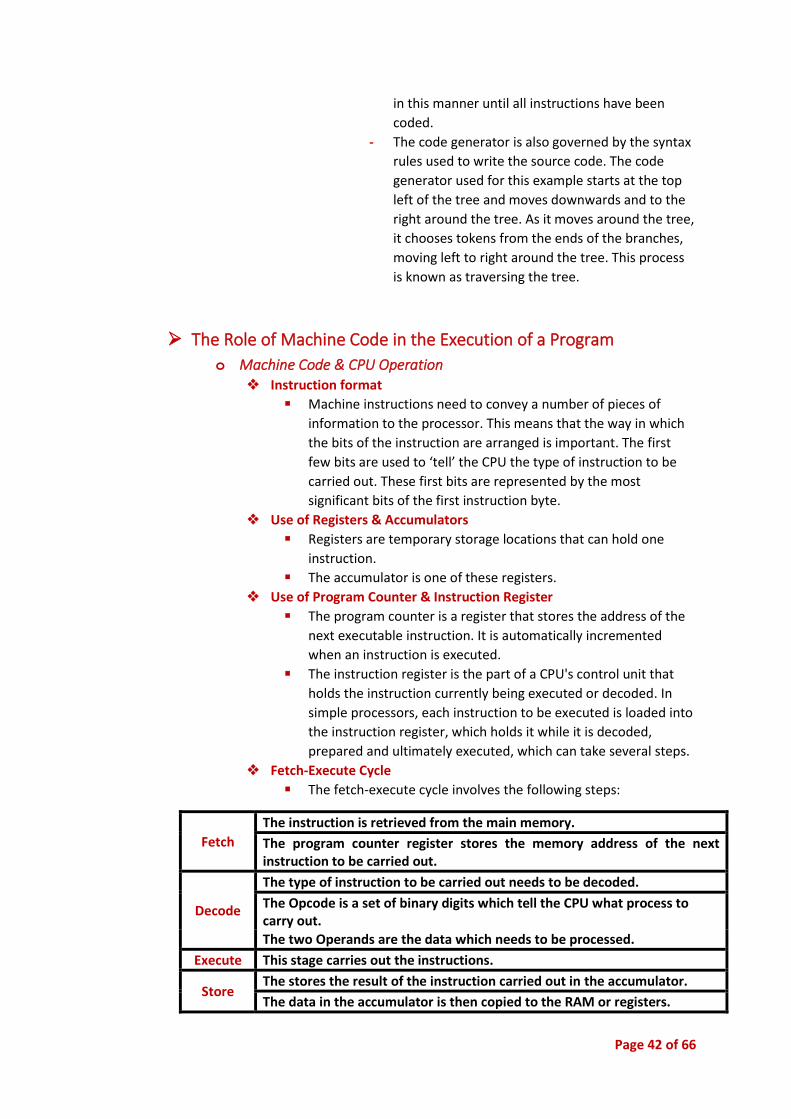
❖ Fetch-Execute Cycle
▪ The fetch-execute cycle involves the following steps:
Fetch
The instruction is retrieved from the main memory.
The program counter register stores the memory address of the next instruction to be carried out.
Decode
The type of instruction to be carried out needs to be decoded.
The Opcode is a set of binary digits which tell the CPU what process to carry out.
The two Operands are the data which needs to be processed.
Execute This stage carries out the instructions.
Store The stores the result of the instruction carried out in the accumulator.
The data in the accumulator is then copied to the RAM or registers.
Page 43 of 66
❖ Addresses of called routines
▪ Commands to be executed are stored with the operation code in
the computer's RAM.
▪ Each memory address is accessed sequentially unless the
instruction is to jump to another part of the program.
❖ Linking, including the use of DLL’s
▪ Linking allows a machine code program to combine with other
machine code programs.
▪ Dynamic link libraries (DLLs) are collections of programs in
machine code which can be accessed by other programs to
perform specific tasks.
➢ Techniques Used in Developing Well-Written Code
o Structured Approach to Complex Solution ❖ One Logical Task Per Subroutine
▪ Coding a subroutine that performs only one task but performs it
efficiently.
▪ Allows it to be low maintenance and reusable.
❖ Stubs
▪ Dummy procedures/modules that supply either/both:
- Some data to allow the calling module to continue working.
- An output statement indicating the stub modules has been
called correctly.
❖ Flags
▪ Boolean variable that indicates that an event has occurred.
❖ Isolation of Errors
▪ Errors can often be located by:
- Using debugging output statements.
- Commenting out sections of code to determine which part
is causing the error.
- Setting break points to exit the program if a certain event
occurs.
❖ Debugging Output Statements
▪ Debugging output statements, such as variable traces, are used
to print the value of a variable at a certain point of the code to
test if the algorithm is operating correctly.
❖ Elegance of Solution
▪ Being able to solve a problem with the minimum amount of
code. It often requires lateral thinking so that unnecessary steps
can be skipped.
❖ Writing for Subsequent Maintenance
▪ Taking the source code and converting it into executable code
that can be executed independently and without the need for a
translator.

Page 44 of 66
o The Process of Detecting & Correcting Errors ❖ Syntax errors
▪ Easily corrected errors in the coding of the solution.
▪ Occur when you do not follow the syntax rules of a language
correctly.
❖ Logic Errors
▪ When a program performs an incorrect action or gives out the
wrong output due to flawed logic.
▪ Must be corrected by testing and debugging through use of
good test data.
❖ Peer Checking
▪ When programmers not involved with the original design are
asked to check the logic of an algorithm or program.
❖ Desk Checking
▪ Stepping through the code of a program on paper with pre-
determined test data to ensure that the desirable output is
achieved.
❖ Use of Expected Output
▪ Inputting the expected variable value manually to test whether
the program manipulates that data correctly.
❖ Runtime Errors, including:
▪ Occur as the object code is being executed. Usually due to an
error in the program's logic.
▪ Arithmetic Overflow
- Occurs when a result cannot be stored in the nominated
memory location due to incorrect use of data types and
structures.
▪ Division by Zero
- Occurs when an undefined arithmetic operation is carried
out – usually when the program attempts to divide a
number by zero.
▪ Accessing Inappropriate Memory Locations
- Occurs if inappropriate memory locations are accessed.
o Use of Software Debugging Tools ❖ Use of Breakpoints
▪ Stopping the execution of code at certain points so that the
value of variables at that point can be observed.
❖ Resetting Variable Contents
▪ The values of a variable can be changed as the program is
executed to determine if the processes being carried out are
accurate.
❖ Program Traces
▪ As the program is run, the actual line of code being executed is
displayed on screen. Variable values can also be viewed.
Page 45 of 66
❖ Single Line Stepping
▪ Stepping through the code one line at a time to see how the
program operates and manipulates variables.
➢ Documentation of a Software Solution
o Forms of Documentation ❖ Process Diary
▪ Design or specification documentation used to describe the
development process.
▪ Includes:
- Screen layout designs
- Data and processing specifications
- Descriptions of input and output
- Also known as a logbook.
❖ User Documentation
▪ Documentation that helps people work/use the products.
▪ Often include screenshots, step-by-step instructions, contents,
index, etc.
▪ Examples of user documentation include:
- User manual
- Installation guide
- Tutorials
- Online help
❖ Self-Documentation of The Code
▪ Commenting of the code makes it easier to understand the
processes involved for both the original developer and any other
developers who wish to maintain the code in the future.
❖ Technical Documentation
▪ Needed by programmers and developers to allow the program
to be modified.
▪ Source code
- The actual programming code that makes up a program.
- Should be well commented to explain any obscure areas
of the code.
- Code should be indented to make it easier to read.
- Meaningful variable names should be used.
▪ Algorithms
- Used to provide a clear description of the steps carried out
to solve a problem.
- Simplifies any program code so it can be understood.
- Common methods of algorithm description include:
Pseudocode
Flowcharts
▪ Data Dictionary
- Used to describe the nature and form of any input data.

Page 46 of 66
▪ Systems Documentation
- Provides a description of the operating system, including
the use of subprograms and any special features of the
code.
❖ Documentation for Subsequent Maintenance of the Source
- Technical documentation should assist programmers in
modifying the code in the future.
- Changes made during maintenance should be
documented for future reference.
o Use of Application Software to Assist in Documentation ❖ CASE tools that help generate user and technical documentation exist
to make the job of the programmer easier.
➢ Hardware Environment to Enable Implementation of The Software
Solution
o Minimum Configuration ❖ Commercial software often specifies the minimum hardware
configuration needed to run.
❖ Includes aspects such as:
▪ CPU type/speed
▪ Amount of hard drive storage
▪ Amount of RAM
▪ Operating system version
o Possible Additional Hardware ❖ If a program is too complex for a system, additional hardware may
need to be purchased or current hardware upgraded.
o Appropriate Drivers or Extensions ❖ Drivers provide a means of accessing input or output hardware
devices.
❖ Extensions enable a program to interact with other programs.

Page 47 of 66
➢ Emerging Technologies
o Hardware ❖ Quantum Computers – Will vastly increase the speed at which
computers can operate.
❖ Nanotechnology – Will allow for the sizes of computers to decrease so
they can be embedded in more places.
❖ Holographic Storage – Expand storage devices to a three-dimensional
level to increase the amount of data that can be stored greatly.
o Software ❖ Java – Allows for the development of cross-platform applications.
Becoming increasingly popular as a programming language.
❖ Dylan – A programming language which extends upon other object-
oriented languages by introducing new data structures such as dynamic
inheritance and parametric polymorphism.
o Their Effect on: ❖ Human Environment
- As new technologies emerge, may people strive to
incorporate them into their lives.
- Most technological items are designed to assist humans in
particular tasks.
- There can be both positive and negative effects due to
technological advance, these should be determined before
a technology is accepted by society.
❖ Development Process
- Software is becoming increasingly cross-platform as the
line between PCs, PDAs, mobile phones, etc. becomes
blurred.
- CASE tools as well as Visual IDEs are assisting
programmers to develop applications more quickly and
more easily.

Page 48 of 66
• Testing & Evaluating of Software Solutions
➢ Testing the Software Solution
o Comparison of the Solution with the Original Design Specification ❖ The solution must meet the original objectives.
❖ Developers must constantly check that the original specifications are
being met.
o Generating Relevant Test Data for Complex Solutions ❖ Test data that will ensure the correct functioning of the algorithm must
be generated.
❖ This often involves data which tests boundary conditions for various
methods.
❖ Sometimes not all procedures can be tested, but developers should
strive for as much testing as possible.
o Levels of Testing ❖ Unit or Module
▪ It is often possible to test a small section of the program by
entering inputs and observing outputs for that module.
▪ If the workings of the module are known it is called white box
testing, but if it is unknown it is called black box testing.
❖ Program
▪ When a program is tested in its entirety, usually by the
developers. This is known as alpha testing.
▪ Often focuses on testing user interfaces and the interaction of
separate modules.
❖ System
▪ Testing the software in a variety of hardware/operating system
environments.
▪ Usually testing is performed by users, this is known as beta
testing.
o The Use of Live Test Data to Test the Complete Solution ❖ Larger File Sizes
▪ Larger file sizes for data structures allows the program to be
tested under heavier, real-world loads.
❖ Mix of Transaction Types
▪ Different transaction types are used in order to test a range of
modules.
❖ Response Times
▪ Response times should be kept to a minimum.
▪ Any response times greater than 1 second should have onscreen
feedback for the user.
❖ Volume Data
▪ Large amounts of data should be used.
▪ Large volumes of transactions should be tested.
❖ Interfaces Between Modules
▪ Every interface that links between modules must be tested.
Page 49 of 66
▪ This includes screens that interface between other applications
and hardware.
❖ Comparison with Program Test Data
▪ The program should be compared with generated expected
output to ensure that the correct outputs are being obtained.
➢ Reporting on the Testing Process
o Documentation of the Test Data & the Output Produced ❖ Use of CASE Tools
▪ Generating test data
▪ Testing user interface designs
▪ Volume testing
o Communication with Consumers ❖ Test Results
▪ It is important to communicate any test results to developers
and customers.
❖ Comparison with Original Design Specifications
▪ Test results must be compared to the original design
specifications to ensure that the final solution meets the criteria.
➢ Evaluating the Software Solution
o Benchmarking ❖ Comparing the performance of the product with competitor’s
products.
o Quality Assurance ❖ Checking how well a solution complies to the user’s expectations,
includes:
▪ Correctness
▪ Efficiency
▪ Flexibility
▪ Integrity
▪ Interoperability
▪ Maintainability/ Modifiability
▪ Portability Reliability
▪ Reusability
▪ Useability
▪ Validity
o Post Implementation Review ❖ Facilitation of open discussion & evaluation with the client
❖ Client sign of process

Page 50 of 66
• Maintaining Software Solutions
➢ Modifying Code to Meet Changed Requirements
o Identification of the Reasons for Change in Code, Macros ❖ Bug fixes ❖ New hardware ❖ New software purchases ❖ Suggested improvements
o Location of Section to be Altered ❖ Models are used to assist finding the section that needs alteration. ❖ A thorough understanding of the original source code is required.
o Determining Changes to be Made ❖ Once the required module is located, IPO charts and algorithms are used
to determine what to modify. ❖ Effect of the changes on other modules must be considered.
o Implementing & Testing Solution ❖ Once the changes have been determined, they must be made in the
source code. ❖ Code must then be recompiled, tested and distributed. ❖ Distribution may be through:
▪ Direct change on the user’s system
▪ Remote change via telecommunication link
▪ User applied patches
➢ Documenting Changes
o Source Code, Macro & Script Documentation ❖ Includes comments and intrinsic documentation. ❖ Improves the maintainability for future changes.
o Modification of Associated Hard Copy Documentation & Online Help ❖ Hard copy documentation may need to be reproduced or a “release
note” may need to be added to outline any changes. ❖ Online documentation would need to be updated if any of the
procedures within the program change.
o Use of CASE Tools to Monitor Changes & Versions ❖ Versioning CASE tools such as CVS can monitor changes in source code
and maintain a log of changes so programmers can see how and why programs have been modified.

Page 51 of 66
Developing a
Solution Package -
Notes
Page 52 of 66
Contents • Designing & Developing a Software Solution to a Problem ................................................... 53
➢ Defining the Problem ...................................................................................................... 53
➢ Understanding ................................................................................................................ 53
➢ Planning & Designing ...................................................................................................... 53
➢ Implementing ................................................................................................................. 53
➢ Testing & Evaluating ....................................................................................................... 53
➢ Maintenance .................................................................................................................. 53
• Whole Project Issues........................................................................................................... 54
➢ Project Management Techniques .................................................................................... 54
Page 53 of 66
• Designing & Developing a Software Solution to a Problem
➢ Defining the Problem o Identification of the problem
o Idea generation
o Communication with others involved in the proposed system
➢ Understanding o Interface design
o Communication with others involved in the proposed system
o Representing the system using diagrams
o Selection of appropriate data structures
o Applying project management techniques
o Consideration of all social and ethical issues
➢ Planning & Designing o Interface design
o Selection of software environment
o Identification of appropriate hardware
o Selection of appropriate data structures
o Production of a data dictionary
o Definition of required validation processes
o Definition of files – record layout and creation
o Algorithm design
o Inclusion of standard or common routines
o Use of software to document design
o Identification of appropriate test data
o Enabling and incorporating feedback from users at regular intervals
o Consideration of all social and ethical issues
o Applying project management techniques
➢ Implementing o Production and maintenance of data dictionary
o Inclusion of standard or common routines
o Use of software to document design
o Translating the solution into code
o Creating online help
o Program testing
o Reporting on the status of the system at regular intervals
o Applying project management techniques
o Enabling and incorporating feedback from users at regular intervals
o Completing all user documentation for the project
o Consideration of all social and ethical issues
o Completing full program and systems testing
➢ Testing & Evaluating
➢ Maintenance o Modifying the project to ensure an improved solution
Page 54 of 66
• Whole Project Issues
➢ Project Management Techniques o Project management techniques are applied to the development of a
solution package.
o Project teams are multi-disciplinary, and outsourcing is employed as
required.
o Defining the problem consists of identifying the problem, ideas generation
and communication with others involved in the proposed system.
o Understanding the problem consists of interface design, communication
with others involved in the proposed system, representing the system using
diagrams, selection of appropriate data structures and consideration of all
social and ethical issues.
o Consideration of all social and ethical issues includes ease of use,
accessibility of technical language, copyright and ergonomics.
o Planning and design consists of interface design, selection of software
environment, identification of appropriate hardware, selection of
appropriate data structures, production of a data dictionary, definition of
required validation processes, definition of files, algorithm design, inclusion
of standard or common routines, use of software to document design,
identification of appropriate test data, enabling and incorporating feedback
from users and applying project management techniques.
o The final stage in developing a solution package is to implement the
solution. This is a two-stage process consisting of implementation and
maintenance.
o Implementation consists of production and maintenance of the data
dictionary, translating the solution into code, creating online help, program
testing and completing all user documentation for the project.
o Maintenance consists of modifying the project to ensure an improved
solution.
o Project management techniques are applied throughout the development of
a solution package.
o Testing of the solution should be carried out at regular intervals—test early
and test often.
Page 55 of 66
The Interrelationship
Between Software &
Hardware - Notes

Page 56 of 66
Contents • Representation of Data Within the Computer ............................................................................ 57
➢ Character Representation ........................................................................................................ 57
o ASCII vs Unicode ....................................................................................................................... 57
➢ Representation of Data Using Different Number Systems ..................................................... 57
o Binary ........................................................................................................................................ 57
o Hexadecimal ............................................................................................................................. 57
o Decimal ..................................................................................................................................... 57
➢ Integer Representation ............................................................................................................ 58
o Sign & Modulus ........................................................................................................................ 58
o 1’s Complement ........................................................................................................................ 58
o 2’s Complement ........................................................................................................................ 58
➢ Floating Point/Real Representation ........................................................................................ 58
o Fixed-Point ................................................................................................................................ 58
o Floating-Point ........................................................................................................................... 58
➢ Binary Arithmetic ..................................................................................................................... 60
o Addition .................................................................................................................................... 60
o Subtraction ............................................................................................................................... 60
o Multiplication ........................................................................................................................... 60
o Division ..................................................................................................................................... 60
• Electronic Circuits to Perform Standard Software Operations ................................................... 61
➢ Logic Gates ................................................................................................................................ 61
➢ Truth Tables .............................................................................................................................. 61
➢ Specialty Circuits ...................................................................................................................... 62
o Half Adder ................................................................................................................................. 62
o Full Adder .................................................................................................................................. 62
o Flip-Flops ................................................................................................................................... 63
• Programming of Hardware Devices ............................................................................................. 64
➢ The Data Stream ....................................................................................................................... 64
o Format of the Data Stream ...................................................................................................... 64
o Use of Control Characters ........................................................................................................ 65
o Error Detection & Correction .................................................................................................... 65
o Clock .......................................................................................................................................... 66
o Use of Hardware Specifications to Describe the Format of the Data Stream ........................ 66

Page 57 of 66
• Representation of Data Within the Computer ➢ A computer can only process binary data (0 or 1). Humans work in decimal numbers
& hence we need to convert decimal to binary & vice-versa. There are limitations on
representation of data which the programmer needs to determine.
➢ The range of acceptable integers (16, 32 or 64 bits)
➢ Maximum size of a real number & how many decimal places that can be used.
➢ The disk space that can be used.
➢ The amount of RAM available for data storage.
➢ Character Representation
o ASCII vs Unicode ❖ ASCII: American Standard Code for Information Interchange.
ASCII Unicode Extended ASCII
American Standard Code for Information Interchange
Universal Character Set
Is a character system where the first 128
characters are exactly the same as
ASCII
7 bits per character 16, 24, or 36 bits per character
128 different characters Between 65536 & 4,294,967,296
characters depending on the system ASCII
All English letters, numbers, & symbols
Contains all major languages, symbols, hieroglyphics, etc.
➢ Representation of Data Using Different Number Systems
o Binary
o Hexadecimal ❖ A number system that uses 16 as its base. Because it requires 16
symbols, the letters A-F are used as digits to represent the decimal
numbers 10-15.
o Decimal

Page 58 of 66
➢ Integer Representation
o Sign & Modulus ❖ Sign & Modulus: this method uses the left-most bit to represent the
sign (0 = +, 1 = -). The remaining bits give the modulus or magnitude
of the number.
❖ Only exists when: -127 > x > 127
❖ Represents + & - numbers.
Sign Modulus
+ 0 1111111 + 127
+ 0 1111000 + 120
+ 0 0011110 + 62
+ 0 0000000
- 1 0000000
- 1 0011111 - 62
- 1 1111111 - 127
o 1’s Complement ❖ One’s Complement: depicts negative numbers by replacing all the
ones in the positive form with zero’s & all the zero’s with ones.
o 2’s Complement ❖ Two’s Complement: represents a negative number by adding 1 to
the one’s complement of the number.
➢ Floating Point/Real Representation
o Fixed-Point ❖ Fixed-point refers to the position of the decimal point. When using
fixed-point numbers, the decimal point remains in the same position
for all numbers. For example, a fixed-point system using 16 bits may
have 8 bits for the whole number part & 8 bits for the fractional
part. The problem with such a system is that very large numbers and
very small numbers cannot be represented.
o Floating-Point ❖ Floating-point numbers can be thought of as generalised fixed-point
numbers. The position of the decimal point is encoded within the
format. In this way, the decimal point can be placed in a different
position within the number. Essentially, the number is stored using
scientific notation.
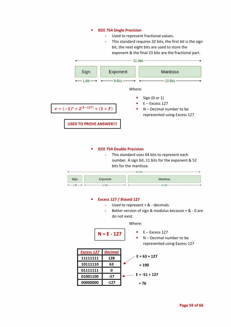
Page 59 of 66
▪ IEEE 754 Single Precision
- Used to represent fractional values.
- This standard requires 32 bits, the first bit is the sign
bit, the next eight bits are used to store the
exponent & the final 23 bits are the fractional part.
▪ IEEE 754 Double Precision
- This standard uses 64 bits to represent each
number. A sign bit, 11 bits for the exponent & 52
bits for the mantissa.
▪ Excess 127 / Biased 127
- Used to represent + & - decimals.
- Better version of sign & modulus because + & - 0 are
do not exist.
Excess 127 Decimal
11111111 128
10111110 63
01111111 0
01001100 -57
00000000 -127
N = E - 127
Where:
▪ E – Excess 127
▪ N – Decimal number to be
represented using Excess 127
E = 63 + 127
= 190
E = -51 + 127
= 76
𝒗 = (−𝟏)𝒔 × 𝟐(𝑬−𝟏𝟐𝟕) × (𝟏 + 𝑭)
Where:
▪ Sign (0 or 1)
▪ E – Excess 127
▪ N – Decimal number to be
represented using Excess 127
USED TO PROVE ANSWER!!!

Page 60 of 66
➢ Binary Arithmetic
o Addition ❖ Addition is the basis of all arithmetic operations inside the computer
& is carried out by the special ALU. The rules are simple:
▪ 0 + 0 = 0
▪ 0 + 1 = 1
▪ 1 + 0 = 1
▪ 1 + 1 = 10 (i.e. carry the 1)
o Subtraction ❖ Subtraction is too hard for computers to perform so instead they
“add negatives”. Essentially, they add the first number to the two’s
complement of the second number.
❖ Rules:
▪ 1 - 0 = 1
▪ 1 - 1 = 0
▪ 0 - 0 = 0
▪ 0 - 1 = 1 (with 1 being borrowed from the next higher bit
position)
o Multiplication ❖ The multiplication of two binary numbers is performed using
addition. Each successive bit of the multiplier is looked at. If it is a 1,
then the multiplicand is written down. If it is a 0 then all zeros are
written down. The numbers in successive lines are shifted one place
to the left of the previous number & then they are all added
together.
o Division ❖ Division of binary numbers can be carried out using long division.
This process involves:
▪ Subtracting the divisor
▪ Shifting the next digit into the remainder until the divider can
be subtracted again.
▪ Repeat above.
Binary can’t be expressed in
negative numbers.

Page 61 of 66
• Electronic Circuits to Perform Standard Software Operations
➢ Logic Gates o Logic gates are hardware circuits that produce a 1 or a 0 output if the input
requirements are satisfied. Logic gates are usually implemented in the
computer using IC’s.
𝑨 . 0 = 0 𝑨 + 𝟎 = 𝑨 De Morgan Theorem
∘ - means denied MAKE
EQUATIONS EVEN
𝑨 . �̅� = 0 𝑨 + �̅� = 1
𝑨 . 𝑨 = 𝑨 𝑨 + 𝑨 = 𝑨 𝑨 . 𝑩̅̅ ̅̅ ̅̅ = �̅� + �̅�
𝑨 . 𝟏 = 𝑨 𝑨 + 𝟏 = 𝟏 𝑨 + 𝑩̅̅ ̅̅ ̅̅ ̅̅ ̅ = �̅� x �̅�
➢ Truth Tables
Name Logic Gate Equation Truth Table
INVERTER
Z = �̅�
A Z
0 1
1 0
AND
𝒁 = 𝑨 . 𝑩
A B Z
0 0 0
0 1 0
1 0 0
1 1 1
NAND (not AND)
𝒁 = 𝑨 . 𝑩̅̅ ̅̅ ̅̅
A B Z
0 0 0
0 1 1
1 0 1
1 1 1
XOR (exclusive OR)
𝒛 = 𝑨 ⊕ 𝑩 = A�̅� + �̅�B
A B Z
0 0 0
0 1 1
1 0 1
1 1 0
XNOR (not exclusive OR)
𝒁 = 𝑨 ⊕ 𝑩̅̅ ̅̅ ̅̅ ̅̅ ̅̅ = AB + �̅� . �̅�
A B Z
0 0 1
0 1 0
1 0 0
1 1 1
OR
𝒁 = 𝑨 + 𝑩
A B Z
0 0 0
0 1 1
1 0 1
1 1 1
NOR (not OR)
𝒁 = 𝑨 + 𝑩̅̅ ̅̅ ̅̅ ̅̅ ̅ A B Z
0 0 1
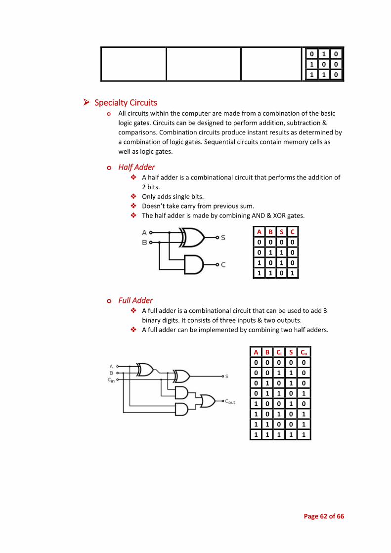
Page 62 of 66
0 1 0
1 0 0
1 1 0
➢ Specialty Circuits o All circuits within the computer are made from a combination of the basic
logic gates. Circuits can be designed to perform addition, subtraction &
comparisons. Combination circuits produce instant results as determined by
a combination of logic gates. Sequential circuits contain memory cells as
well as logic gates.
o Half Adder ❖ A half adder is a combinational circuit that performs the addition of
2 bits.
❖ Only adds single bits.
❖ Doesn’t take carry from previous sum.
❖ The half adder is made by combining AND & XOR gates.
o Full Adder ❖ A full adder is a combinational circuit that can be used to add 3
binary digits. It consists of three inputs & two outputs.
❖ A full adder can be implemented by combining two half adders.
A B S C
0 0 0 0
0 1 1 0
1 0 1 0
1 1 0 1
A B Ci S Co
0 0 0 0 0
0 0 1 1 0
0 1 0 1 0
0 1 1 0 1
1 0 0 1 0
1 0 1 0 1
1 1 0 0 1
1 1 1 1 1
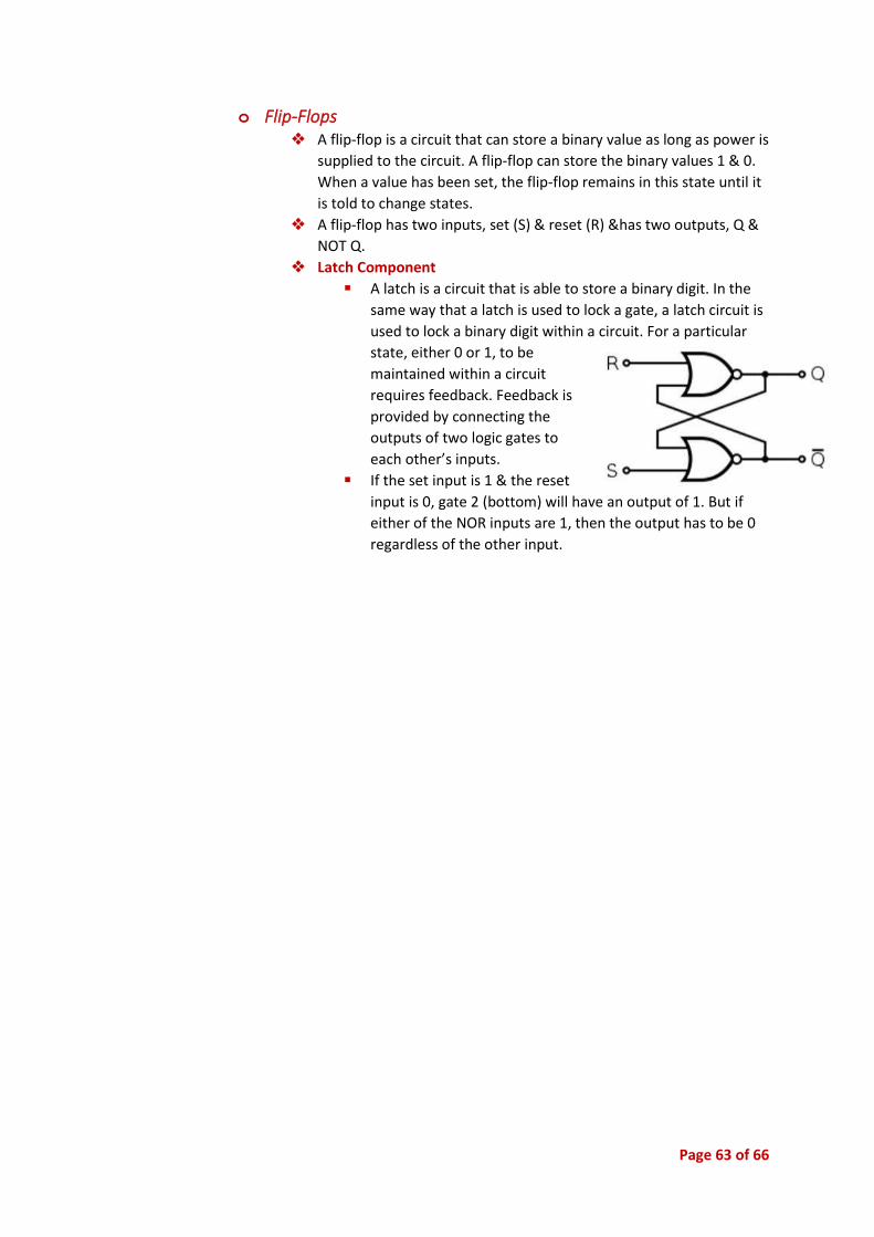
Page 63 of 66
o Flip-Flops ❖ A flip-flop is a circuit that can store a binary value as long as power is
supplied to the circuit. A flip-flop can store the binary values 1 & 0.
When a value has been set, the flip-flop remains in this state until it
is told to change states.
❖ A flip-flop has two inputs, set (S) & reset (R) &has two outputs, Q &
NOT Q.
❖ Latch Component
▪ A latch is a circuit that is able to store a binary digit. In the
same way that a latch is used to lock a gate, a latch circuit is
used to lock a binary digit within a circuit. For a particular
state, either 0 or 1, to be
maintained within a circuit
requires feedback. Feedback is
provided by connecting the
outputs of two logic gates to
each other’s inputs.
▪ If the set input is 1 & the reset
input is 0, gate 2 (bottom) will have an output of 1. But if
either of the NOR inputs are 1, then the output has to be 0
regardless of the other input.
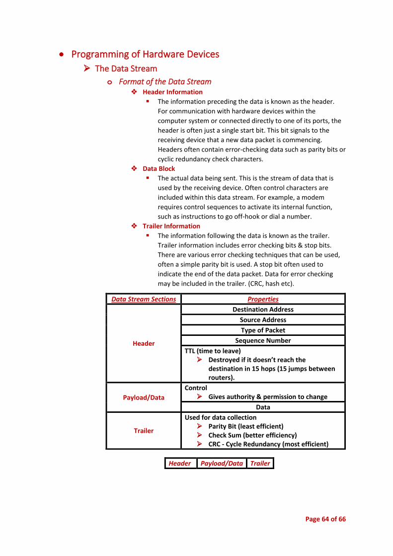
Page 64 of 66
• Programming of Hardware Devices
➢ The Data Stream
o Format of the Data Stream ❖ Header Information
▪ The information preceding the data is known as the header.
For communication with hardware devices within the
computer system or connected directly to one of its ports, the
header is often just a single start bit. This bit signals to the
receiving device that a new data packet is commencing.
Headers often contain error-checking data such as parity bits or
cyclic redundancy check characters.
❖ Data Block
▪ The actual data being sent. This is the stream of data that is
used by the receiving device. Often control characters are
included within this data stream. For example, a modem
requires control sequences to activate its internal function,
such as instructions to go off-hook or dial a number.
❖ Trailer Information
▪ The information following the data is known as the trailer.
Trailer information includes error checking bits & stop bits.
There are various error checking techniques that can be used,
often a simple parity bit is used. A stop bit often used to
indicate the end of the data packet. Data for error checking
may be included in the trailer. (CRC, hash etc).
Header Payload/Data Trailer
Data Stream Sections Properties
Header
Destination Address
Source Address
Type of Packet
Sequence Number
TTL (time to leave) ➢ Destroyed if it doesn’t reach the
destination in 15 hops (15 jumps between routers).
Payload/Data
Control ➢ Gives authority & permission to change
Data
Trailer
Used for data collection ➢ Parity Bit (least efficient) ➢ Check Sum (better efficiency) ➢ CRC - Cycle Redundancy (most efficient)

Page 65 of 66
o Use of Control Characters ❖ Control characters permit the checking & correct reassembling of a
message. A packet contains control characters to enable correct
interpretation of the packet.
o Error Detection & Correction ❖ Parity Bit
▪ Even Parity
- When the number of 1’s is even . Then parity bit is 0.
▪ Odd Parity
- When the number of 1’s is odd . Then parity bit is 1.
START & STOP can never be 0.
Add a 0 to keep even.
Add a 1 to make it even.
▪ Used to check if the electromagnetic noise has affected the
result.
▪ When sending information:
- If the noise level is above the 1 level, then it recognises
it as 1.
Vinay Venkat Sends A
(10100000101)
If the byte is odd & the result
is even. It knows there is an
error from the parity bit. A 0
or 1 parity indicates its initial
number of 1’s.
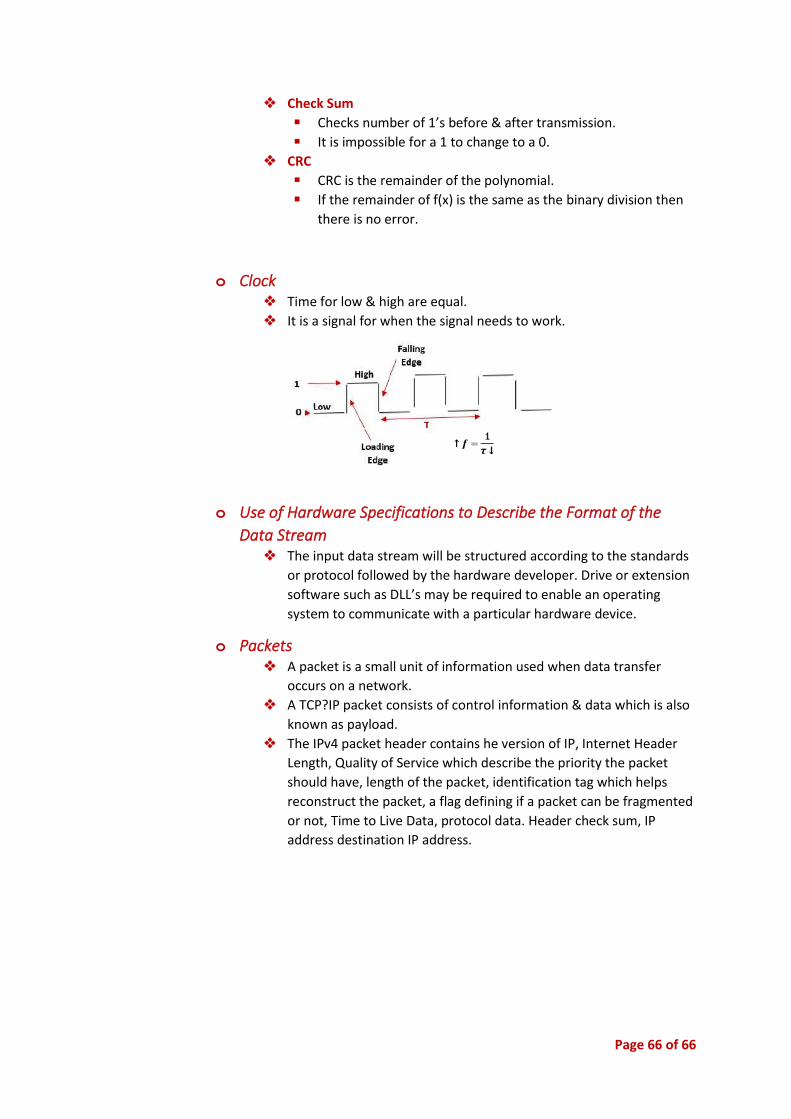
Page 66 of 66
❖ Check Sum
▪ Checks number of 1’s before & after transmission.
▪ It is impossible for a 1 to change to a 0.
❖ CRC
▪ CRC is the remainder of the polynomial.
▪ If the remainder of f(x) is the same as the binary division then
there is no error.
o Clock ❖ Time for low & high are equal.
❖ It is a signal for when the signal needs to work.
o Use of Hardware Specifications to Describe the Format of the
Data Stream ❖ The input data stream will be structured according to the standards
or protocol followed by the hardware developer. Drive or extension
software such as DLL’s may be required to enable an operating
system to communicate with a particular hardware device.
o Packets ❖ A packet is a small unit of information used when data transfer
occurs on a network.
❖ A TCP?IP packet consists of control information & data which is also
known as payload.
❖ The IPv4 packet header contains he version of IP, Internet Header
Length, Quality of Service which describe the priority the packet
should have, length of the packet, identification tag which helps
reconstruct the packet, a flag defining if a packet can be fragmented
or not, Time to Live Data, protocol data. Header check sum, IP
address destination IP address.