developing a polarimeter to determine the optical · developing a polarimeter to determine the...
TRANSCRIPT
Developing a Polarimeter to determine the optical constants of materials in the XUV
Raymond Rios
Research Advisor: Dr. Steve Turley
Abstract: This research paper discusses the progress made in developing a XUV polarimeter, a method for determining the optical constants of in the range of light with wavelengths measuring between 111m to 50ilm. Current methods of determining these constants with ellipsometry have been limited in their ability due to their high absorption coefficients in this wavelength region. The Polarimeter shows intensity variations using both Channeltron and CCD camera detectors due to the rotation of two mirrors relative to each other. It is hoped that these variations are consistent with predicted changes due to polarization which would lead, through mathematical modeling, to the optical constants of the mirrors. Also included in this paper are operating and alignment procedures for the polarimeter.
Table of Contents 1. Introduction
i. Background ii. Project objectives iii. Project accomplishments
2. Construction and Testing of Polarimeter i. Channeltron verses CCD camera ii. Optimizing Channeltron iii. Construction of adjustable aperture iv. Calculating the expected number of counts for the channeltron v. Procedural techniques and complications with Channeltron vi. Procedural techniques and complications with CCD camera
3. Data Results i. Channeltron detector ii. CCD camera 4. Conclusions 5. Appendix A: Standard Operating Procedures i. Taking monochrometor to vacuum ii. Turning on Source iii. Taking O-chamber and Polarimeter to vacuum iv. Making measurements with a Channeltron detector v. Making measurements with a CCD camera vi. Shutting off Source and bring up monochrometor to roughing vii. Bringing O-chamber and Polarimeter to ATM 6. Appendix B: Alignment Procedures i. Alignment procedures for the Polarimeter pinhole ii. Alignment procedures for the Channeltron detector 7. Appendix C: Project Accomplishments i. Work Done on Project ii. Data Analysis Results ii. Miscellaneous correlating research work
Table of Images Figure 1: Polarimeter with channeltron detector attached to O-chamber
Figure 2: Simplified Polarimeter design
Figure 3: Possible view of light beam movement after passing through the polarimeter
Figure 4: Adjustable Pinhole design
Figure 5: Polarimeter measurement setup using the channeltron detector
Figure 6: Entrance to the Polarimeter taken from inside the O-chamber
Figure 7: Polarimeter measurement setup using the CCD camera
Figure 8: Polarimeter measurements using the channeltron detector
Figure 9: Polarimeter measurements using the CCD detector with background
interference.
Figure 10: Background with Background light
Figure 11: Background with background light diminished
Figure 12: Alignment technique for the pinhole to the polarimeter.
Figure 1: Polarimeter with channeltron detector attached to 0-chamber
REU Summer Research Goal:
Development of a polarimeter to determine the optical properties of materials in
the extreme ultraviolet.
Background:
Over the past two years, the Brigham Young University physics department has
been examining the development of a polarimeter used to find the reflectance of
materials in the XT-TV range of light (10 to 40 eV in the electromagnetic
spectrum). . Because sensitivity and difficulty of measuring material properties in
this range with previous methods, the optical properties of materials in the XUV
have been are relatively uncertain. To find the optical properties of materials, it is
important to know some of the properties of the XUV source that is used in the
measurement. Using monochromatic and polarized light, we restrict the amount of
variables that can influence the reflection of the light. BYU has a monochrometor that
provides a relatively steady monochromatic light source.
Unfortunately the monochrometor does not polarize the light. In order to eliminate the
need for polarized light, we have built a polarimeter that does not require the light to be
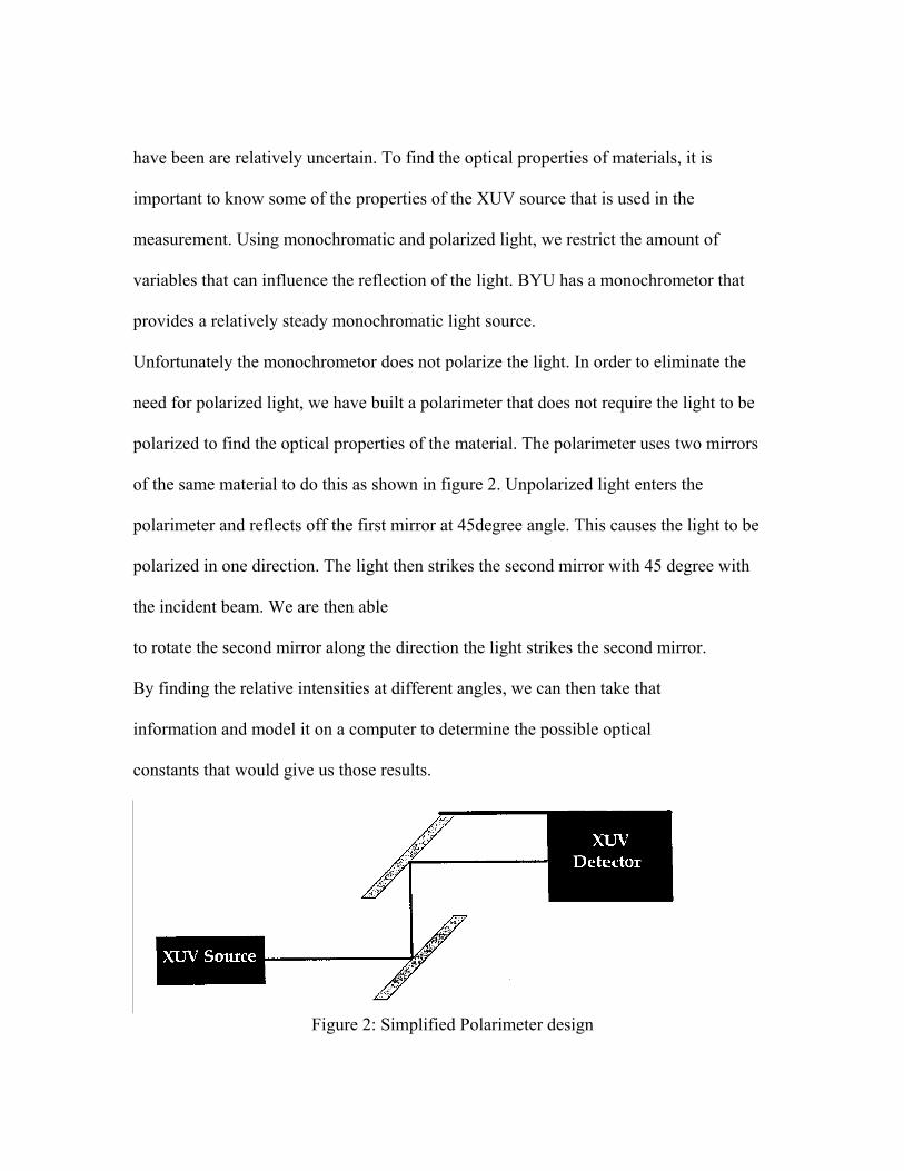
polarized to find the optical properties of the material. The polarimeter uses two mirrors
of the same material to do this as shown in figure 2. Unpolarized light enters the
polarimeter and reflects off the first mirror at 45degree angle. This causes the light to be
polarized in one direction. The light then strikes the second mirror with 45 degree with
the incident beam. We are then able
to rotate the second mirror along the direction the light strikes the second mirror.
By finding the relative intensities at different angles, we can then take that
information and model it on a computer to determine the possible optical
constants that would give us those results.
Figure 2: Simplified Polarimeter design
Research this summer:
This summer I will test the polarimeter with materials that have accepted
values in the XUV and then compare them to determine the effectiveness of the
polarimeter. If time permits, I will test other materials that will be useful for
development in thin multilayer mirrors that can be used for space, lithography and
XUV laser applications in the future.
Channeltron Versus CCD:
The Polarimeter was designed to be used by either a CCD camera or
Channeltron detector. Because both the channeltron and the CCD camera have
they're own distinct advantages in taking measurements, part of this research was
to determine which detector was best suited for the polarimeter.
The number of photons recorded by the channeltron is summed up over
the area it's detection area. This light sensitive area on the channeltron is called
the CEM. The CCD camera uses a matrix of extremely small optically sensitive
semiconductors. Unlike the CCD camera, which can provide thousands of data
points for one measurement, the channeltron provides only one. When compared
to the CCD camera, the channeltron detector has some benefits as well as some
drawbacks.
While the CCD camera has more data points, the channeltron only has one
which decreases the processing time required by the computer and hence the
overall measurement duration. This is important because we find that the light
source to be unstable and has a tendency to fluctuate in intensity. Since the overall
measurement will be shorter with the channeltron than the CCD camera, the beam
intensity is less likely to wander as far compared to the amount of time it takes to
make measurements with the CCD camera. Also, since there is only one data
point, the data can be taken directly as opposed to determining the relative
number of photons that hit the CCD camera by having to process each image in
Matlab or some other program.
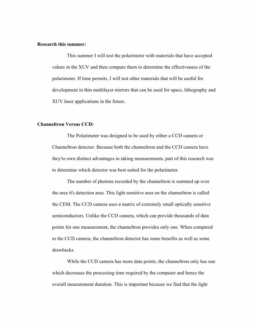
Unfortunately, the channeltron does not provide any other information
about the beam itself. The CCD camera, while it does take longer to record and
process the results from the measurement, gives the user much more information
about the beam. For example: beam image, position and uniformity.
Figure 3: Possible view of light beam movement after passing through the polarimeter Optimizing Channeltron:
We determined that the channeltron is best suited for measurements done by the
polarimeter so long as two requirements are met: One, the beam position
remained either stationary or uniform and two, the surface area of the CEM was
large enough to collect enough counts to analyze. In using the channeltron we
have two options:
1. Completely cover the entrance hole with the beam
2. Limit the beam size so that all of it enters the entrance hole
Only having part of the beam enter the hole will not do because by rotating the
beam even with small fluctuations in the beams position can alter greatly the
relative number of counts and through off the measurements.
By covering the entrance hole completely we get the most counts possible.
Plus the beam has more flexibility if it moves while rotating the second mirror.
The one concern is that if beam is not uniform, then as the mirror is rotated the
intensity will vary do to both polarization and changes in the beam intensity.
When the beam is limited to within the diameter of the detector hole then
variations of intensity with in the beam do not matter since the entire beam enters
the entrance hole. Limiting the beam has its own problems though. The number of
counts drops, which, when dealing with reflection off of two mirrors in the XUV
range, is a major concern. The other problem is that the beam may wander and not
hit the detector completely. To keep the beam from wandering, a movable pinhole
is positioned so that the beam strikes the center of rotation of both mirrors and
thus keeps the beam's position stationary. The tolerance in the beam's movement
is limited by the size of the beam. The larger the beam means more counts but
less flexibility and more likelihood that the beam moves slightly out of the

entrance hole.
If the beam intensity is uniform over the entire width, then the best
solution is to completely cover the entrance slit. One concern may be that by
making the beam too large there might be internal reflection inside the
polarimeter that still makes it into the detector. Such effects on the measurements
should be minimal since the intensity of the beam dies off dramatically with each
reflection. If there remains any concern, the beam should remain large enough to
cover the entrance hole with flexibility in movement yet small enough to keep the
beam away from the walls of the polarimeter and the size of the beam.
Construction of Adjustable Aperture:
During the initial course of this
research, the uniformity of the beam
was unknown. There was a possibility
that the concentration of the beam laid
in the center and the diminished
radially outward. The alignment of the
detector was crucial to make certain
that it captured only the light that
reflected at the center of rotation. Set
screws were used to allow the pinhole
to be adjustable. The diagram in figure
4 shows the design used for the
construction
of the pinhole.
Procedures for aligning the polarimeter pinhole and detector see Appendix B. Calculating the expected amount of counts through polarimeter:
It is important to know what the expected amount of counts should be when
determining whether or not the polarimeter is working properly. This can be
accomplished by taking the number of counts made by the channeltron detector
within the O-chamber a small distance before the beam strikes the polarimeter
aperture. By comparing the relative sizes of the entrances to the polarimeter and
detector and multiplying them by the percentages of reflection at 45-degrees from
two mirrors, the number of counts will be scaled to the expected output value of
the detector. We can then compare this result to actual measurements to see if
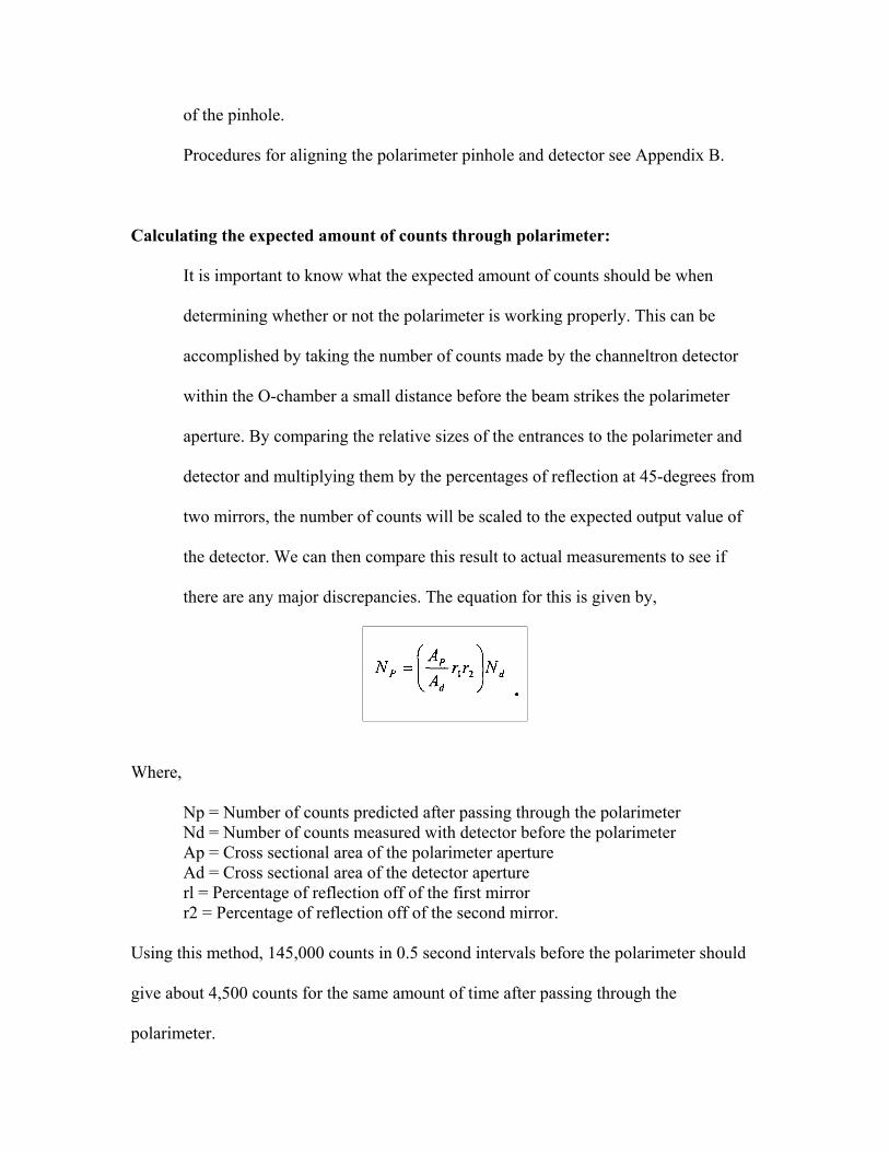
there are any major discrepancies. The equation for this is given by,
Where,
Np = Number of counts predicted after passing through the polarimeter Nd = Number of counts measured with detector before the polarimeter Ap = Cross sectional area of the polarimeter aperture Ad = Cross sectional area of the detector aperture rl = Percentage of reflection off of the first mirror r2 = Percentage of reflection off of the second mirror.
Using this method, 145,000 counts in 0.5 second intervals before the polarimeter should
give about 4,500 counts for the same amount of time after passing through the
polarimeter.
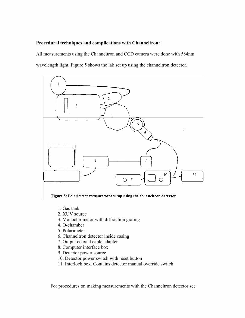
Procedural techniques and complications with Channeltron:
All measurements using the Channeltron and CCD camera were done with 584nm
wavelength light. Figure 5 shows the lab set up using the channeltron detector.
1. Gas tank 2. XUV source 3. Monochrometor with diffraction grating 4. O-chamber 5. Polarimeter 6. Channeltron detector inside casing 7. Output coaxial cable adapter 8. Computer interface box 9. Detector power source 10. Detector power switch with reset button 11. Interlock box. Contains detector manual override switch
For procedures on making measurements with the Channeltron detector see
Appendix A
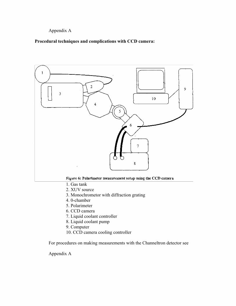
Procedural techniques and complications with CCD camera:
1. Gas tank 2. XUV source 3. Monochrometor with diffraction grating 4. 0-chamber 5. Polarimeter 6. CCD camera 7. Liquid coolant controller 8. Liquid coolant pump 9. Computer 10. CCD camera cooling controller
For procedures on making measurements with the Channeltron detector see
Appendix A
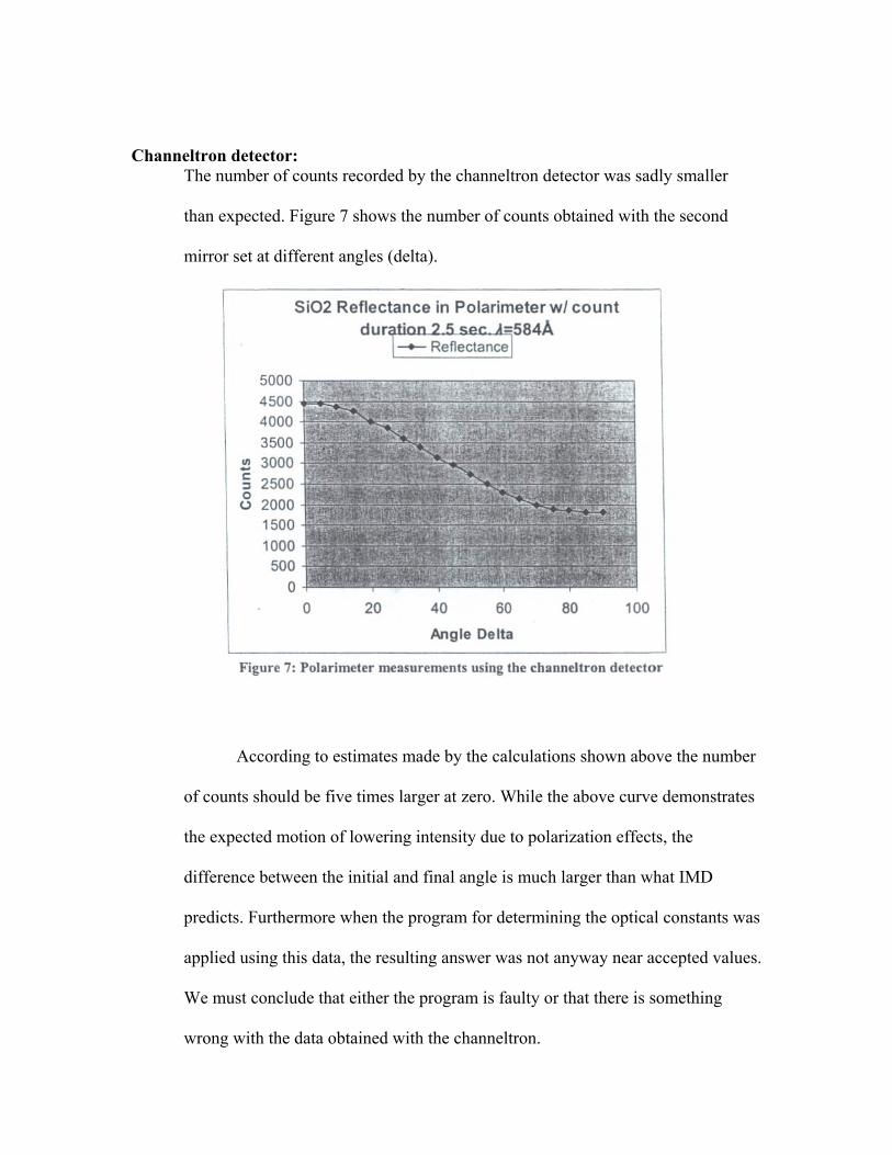
Channeltron detector: The number of counts recorded by the channeltron detector was sadly smaller
than expected. Figure 7 shows the number of counts obtained with the second
mirror set at different angles (delta).
According to estimates made by the calculations shown above the number
of counts should be five times larger at zero. While the above curve demonstrates
the expected motion of lowering intensity due to polarization effects, the
difference between the initial and final angle is much larger than what IMD
predicts. Furthermore when the program for determining the optical constants was
applied using this data, the resulting answer was not anyway near accepted values.
We must conclude that either the program is faulty or that there is something
wrong with the data obtained with the channeltron.
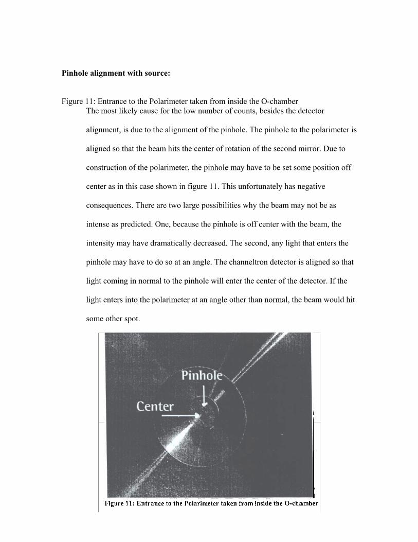
Pinhole alignment with source:
Figure 11: Entrance to the Polarimeter taken from inside the O-chamber
The most likely cause for the low number of counts, besides the detector
alignment, is due to the alignment of the pinhole. The pinhole to the polarimeter is
aligned so that the beam hits the center of rotation of the second mirror. Due to
construction of the polarimeter, the pinhole may have to be set some position off
center as in this case shown in figure 11. This unfortunately has negative
consequences. There are two large possibilities why the beam may not be as
intense as predicted. One, because the pinhole is off center with the beam, the
intensity may have dramatically decreased. The second, any light that enters the
pinhole may have to do so at an angle. The channeltron detector is aligned so that
light coming in normal to the pinhole will enter the center of the detector. If the
light enters into the polarimeter at an angle other than normal, the beam would hit
some other spot.

It is possible that because the beam enters at an angle the beam no longer hits the
center of rotation and therefore moves when the second mirror is rotated. The
beam may then not completely enter the detector and cause the intensity to
decrease more than it normally would if stayed in the same position. To see if the
problem is due to the channeltron. this same measurement was done using a CCD
camera.
CCD camera:
While taking pictures of the XUV beam with the CCD camera, strange images
appeared that gave concern as to what was happening within the polarimeter.
Figure 8: Polarimeter measurements using the CCD detector with background interference.
Figure 8 shows images taken at adjusted angles using a CCD camera with
exposure of two minutes. The background mask is taken with the polarimeter set
at zero. Assuming that natural light has no effect on the camera, it appears that
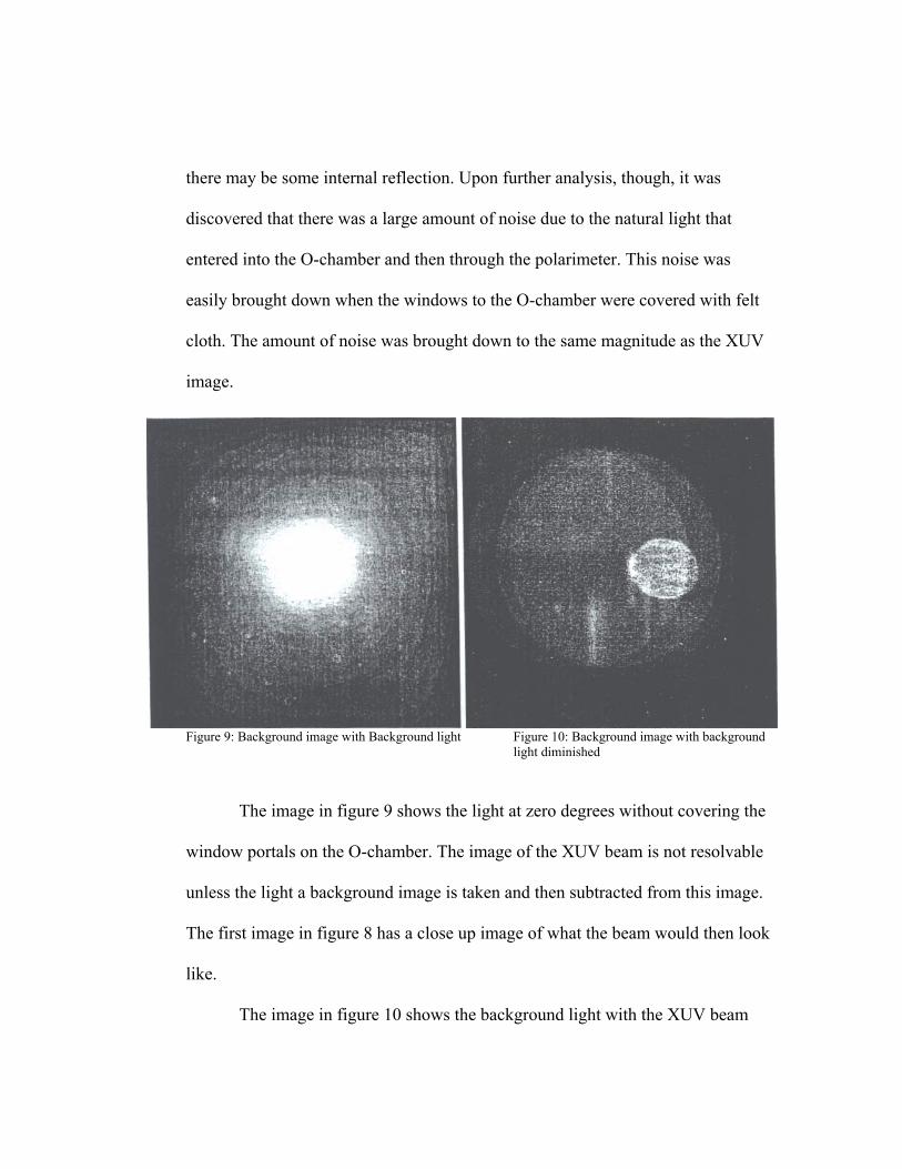
there may be some internal reflection. Upon further analysis, though, it was
discovered that there was a large amount of noise due to the natural light that
entered into the O-chamber and then through the polarimeter. This noise was
easily brought down when the windows to the O-chamber were covered with felt
cloth. The amount of noise was brought down to the same magnitude as the XUV
image.
Figure 9: Background image with Background light Figure 10: Background image with background light diminished
The image in figure 9 shows the light at zero degrees without covering the
window portals on the O-chamber. The image of the XUV beam is not resolvable
unless the light a background image is taken and then subtracted from this image.
The first image in figure 8 has a close up image of what the beam would then look
like.
The image in figure 10 shows the background light with the XUV beam
clearly visible once the image is scaled down in intensity. By accounting for this
by subtracting the background noise a clear image results. This however must be
done for each angle and results in doubling the amount of time needed to make a
complete set of measurements. Measurements such as this can be done with both
the portals covered or uncovered. They will both show images such as found in
the first image in figure 8 at all angles; however, by covering the portals, the
image resolution is sharper at higher angles.
The images produced by the CCD camera show that the beam intensity is
uniform over the entire area. It also shows that the diameter of the beam is about
2.6mm which is small enough to enter the 3mm diameter channeltron detector
hole.
Conclusions:

Appendix A Standard Operating Procedures:
Taking monochrometor to vacuum: Make sure Butterfly valve between monochrometor and O-chamber is closed
and the source valve is open Check to see if roughing pump is running Check to see if cooling water is flowing Turn turbo pump on Turn thermal couple gauge on Wait for turbo pump to reach normal operating speed Turn on cold cathode gauge
Turning on Source:
Open gas line valve thermal couple gauge should read between 500-900 mmhg
Wait 15-20 minutes or longer before turning on source (this appears to keep the source more stable once the power is on)
Check to see if cooling water is flowing Check to see if monochrometor is under vacuum Check to see that source
valve is open Turn on voltmeter Flip circuit breakers on from left to right Press Green button power on Turn voltage knob to 40, voltage should be around 700 Volts on gauge Current should jump up. If not close source valve and then open once it does Current should read around 0.50 A
Taking O-chamber and Polarimeter to vacuum:
Butterfly valve closed Argon line valve closed Gate valve closed Vacuum cap on O-chamber in place Turn on roughing pump Open gate valve Turn on turbo pump Wait until turbo pump reaches normal operating speed Turn on cold cathode gauge
Making measurements with a Channeltron detector:
Connect coaxial cable from computer to the output box next to the Polarimeter Check to see that there is no obstruction within the O-chamber. (Stage and 0-
chamber detector are out of the way of the beam's path)
Open up the channeltron program Enter wavelength setting shown on monochrometor.
Set time duration to 1 or 2 seconds Set data collection to continuous Make sure that the O-chamber is below 5x10^-5 Torr before turning on
detector Turn on power box to detector Flip override switch labeled "detector" Flip Detector switch next to the cold cathode gauge on Push "Collect data" on channeltron program Push reset button on Open Butterfly valve Wait for the output to steady then record in note book next to the angle and
also the range at which the counts are reading Rotate Polarimeter and repeat set 13 Once finished close Butterfly valve Turn off all three detector power switches
Making measurements with a CCD camera:
With the CCD camera connected to the back of the Polarimeter and under vacuum, turn on liquid coolant. It has two switches on to the pump and on to the control box
Push index until you see the LED label read CL Set CL to 20C by pushing the arrow buttons. (This is what room temperature
should be around. The control box to this cooling system is not calibrated and resets to some random number each time it is turned on. It needs to be at a higher temperature than your goal so that it will cool the liquid coolant.)
Push index until you see A1 Set Al to some number above 20C. (This is Alarm one and the LED indicator
should light up if the temperature is below this setting however it doesn't work like that and lights up if the temperature is above this setting. I don't know if it effects the cooling but I set it above my temperature so as not to cause any concern. Precise cooling temperature is not necessary since this is just the supporting cooling system)
Make sure goal is at -20C Turn on controller located beneath the computer monitor Turn cooling knob to
-50C Turn on cooling switch on controller Once the green light is on then the CCD camera is at that temperature Seal off all window portals on O-chamber to light Open Winview on windows 98 computer Go to "Environment", "Setup" In the label box "name of sample +time
interval + angle + `back"' Set time interval to desired time (between 2 and 10 minutes)
Under the "Data Corrections" tab deselect background Make sure butterfly valve is closed Push "Acquire" Once finished, go to "Environment", "Setup" In the label box "name of
sample +time interval + angle" Under the "Data Corrections" tab select background and name "name of
sample +time interval + angle + `back"' (same name as was in step 12) Open butterfly valve Push "Acquire" After it's done, close butterfly valve. Repeat steps 12 to 22 for different angles keeping in mind the need to make
measurements for all the angles in one session and as quickly as possible to keep conditions with the source relatively consistent.
Once finished, turn off all cooling switches Turn off controller Make sure butterfly valve is closed. Give the CCD camera time to come back up to temperature before bringing 0
chamber to atmosphere. Shutting off Source and bring up monochrometor to roughing:
Butterfly valve closed Source valve open Turn off cold cathode gauge Turn voltage knob on power source to zero Push red reset button Flip circuit breaker switches off from right to left Close off gas valves Turn off Thermal couple gauge Turn off Voltmeter Turn off angle alignment motor Push "Stop" on turbo pump Leave roughing pump on
Bringing 0-chamber and Polarimeter to ATM:
Close gate valve. Butterfly valve closed Turn off Turbo pump on interlock box Turn off roughing pump on interlock box Turn on Argon switch on interlock box Open up gas valves to Argon tank Open gas valve above o-chamber Wait until the vacuum cap can be removed easily, but leave on. Close gas valves to Argon tank Close gas valve above O-chamber Turn off Argon switch on interlock box
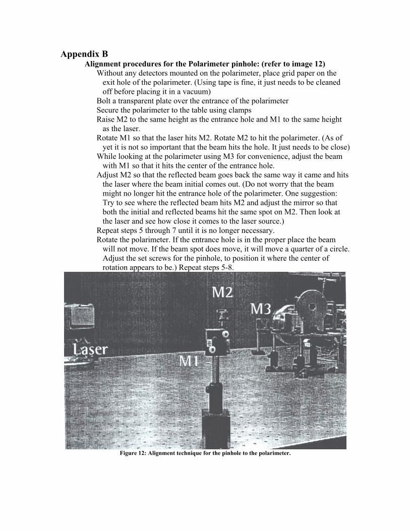
Appendix B Alignment procedures for the Polarimeter pinhole: (refer to image 12)
Without any detectors mounted on the polarimeter, place grid paper on the exit hole of the polarimeter. (Using tape is fine, it just needs to be cleaned off before placing it in a vacuum)
Bolt a transparent plate over the entrance of the polarimeter Secure the polarimeter to the table using clamps
Raise M2 to the same height as the entrance hole and M1 to the same height as the laser.
Rotate M1 so that the laser hits M2. Rotate M2 to hit the polarimeter. (As of yet it is not so important that the beam hits the hole. It just needs to be close)
While looking at the polarimeter using M3 for convenience, adjust the beam with M1 so that it hits the center of the entrance hole.
Adjust M2 so that the reflected beam goes back the same way it came and hits the laser where the beam initial comes out. (Do not worry that the beam might no longer hit the entrance hole of the polarimeter. One suggestion: Try to see where the reflected beam hits M2 and adjust the mirror so that both the initial and reflected beams hit the same spot on M2. Then look at the laser and see how close it comes to the laser source.)
Repeat steps 5 through 7 until it is no longer necessary. Rotate the polarimeter. If the entrance hole is in the proper place the beam
will not move. If the beam spot does move, it will move a quarter of a circle. Adjust the set screws for the pinhole, to position it where the center of rotation appears to be.) Repeat steps 5-8.
Figure 12: Alignment technique for the pinhole to the polarimeter.
Alignment procedures for the Channeltron detector: Place the detector mount without the detector onto the polarimeter Take a piece of clear tape and place it over the exit hole Rotate the polarimeter and check to see if the spot moves. If the spot does move, make sure that the laser is aligned properly by checking to see if the beam returns back to the laser. (This assumes that you still have the transparent plate mounted on the polarimeter.) If it continues to rotate excessively, follow previous procedure again. Mark the spot where the laser hits the tape with a felt tip pen. Take the mount off the polarimeter (that includes the taped exit hole) Put the detector on the mount. Look at the detector entrance through the mount to make sure that the mark is in the center of the detector opening. When the detector is in place screw in the detector with the set screws so that it stays in that spot. Take the detector of with its support. Remove the tape and put the detector
with its support back onto the mount. Make sure not to bump the set screws.