developement of system design code for heliotron...
TRANSCRIPT
Developement of System Design Code
for Heliotron Reactors
Takuya GOTO, Akio SAGARA and Shinsaku IMAGAWA
National Institute for Fusion Science
Japan-US Workshop on
Fusion Power Plants and Related Advanced Technologies
with participation of China
16-18th March, 2009 Kashiwa Campus, The University of Tokyo

Japan-US WS on Fusion Power Plants and Related Advanced Technologies
16-18th March 2009, Kashiwa Campus, The Univ. of Tokyo2/19
Outline
1. Introduction
2. Required performance of system code
3. Consideration of simplified calculation method
– Approximation formula
– Inter/extrapolation
4. Summary and future work

Japan-US WS on Fusion Power Plants and Related Advanced Technologies
16-18th March 2009, Kashiwa Campus, The Univ. of Tokyo3/19
1. Introduction
• Heliotron reactors inherently has suitable properties as a commercial plant
– Free from any operational restriction caused by a plasma current(e.g., possibility of high density operation � low divertor heat load)
– No need of current drive power (low recirculation power � high plant efficiency)
• LHD has achieved good plasma properties:
– High averaged beta <β>=5.1%– High density ne(0)=1.2×10²¹m-3 (SDC-IDB)
• The design study of FFHR has progressed
• We have a perspective of designing a heliotron power plant
Japan-US WS on Fusion Power Plants and Related Advanced Technologies
16-18th March 2009, Kashiwa Campus, The Univ. of Tokyo4/19
• Oft-expressed disadvantages of heliotron system:
– Narrow Space between coil and plasma
– Low confinement due to non-axisymmetric property
– Difficulties in design and construction
Introduction(cont’d)
� Can be compensated by selecting adequate design
point (e.g., FFHR-2m2: enlarging plasma size
compatible with a moderate construction cost)
� LHD was successfully constructed and has been in
operation for over 10 years
Numerical/engineering technology has been progressed
Japan-US WS on Fusion Power Plants and Related Advanced Technologies
16-18th March 2009, Kashiwa Campus, The Univ. of Tokyo5/19
Introduction(cont’d)
• Right now, problems lie in a design study of heliotron system are
– Low number of the existing device and (at present) no existence of an experimental reactor prior to DEMO
– Difficulties in an interpretation of experimental results and prediction of plasma performance (high degree of freedom in design and a requirement of complicated 3D calculation)
• These points lead to low reliability in a prediction of plant performance and difficulty in an optimization of design point.

Japan-US WS on Fusion Power Plants and Related Advanced Technologies
16-18th March 2009, Kashiwa Campus, The Univ. of Tokyo6/19
Purpose of This Study
• For a proposal of a feasible design point, we need to
find a design window with not fully optimized, but
“robust” design points.
• These points should be selected with a consideration
of total system design.
• Sensitivity analyses over a wide design space are
needed.
�Attempted to develop a system design code
Japan-US WS on Fusion Power Plants and Related Advanced Technologies
16-18th March 2009, Kashiwa Campus, The Univ. of Tokyo7/19
2. Required performance of system code
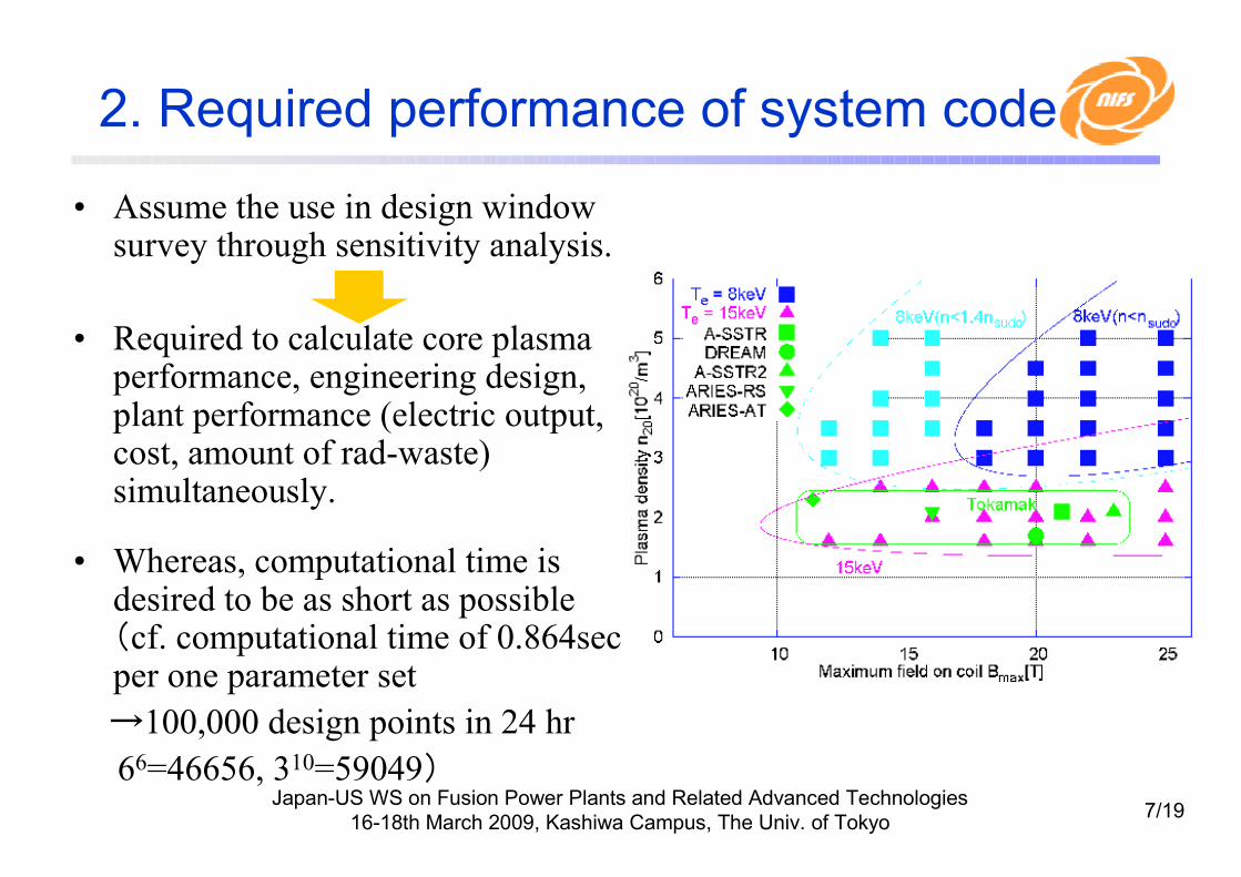
• Assume the use in design window survey through sensitivity analysis.
• Required to calculate core plasma performance, engineering design, plant performance (electric output, cost, amount of rad-waste) simultaneously.
• Whereas, computational time is desired to be as short as possible (cf. computational time of 0.864sec per one parameter set
→100,000 design points in 24 hr
66=46656, 310=59049)
Japan-US WS on Fusion Power Plants and Related Advanced Technologies
16-18th March 2009, Kashiwa Campus, The Univ. of Tokyo8/19
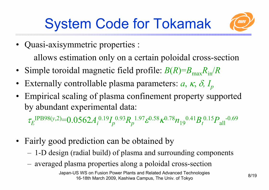
System Code for Tokamak
• Quasi-axisymmetric properties :
allows estimation only on a certain poloidal cross-section
• Simple toroidal magnetic field profile: B(R)=BmaxRin/R
• Externally controllable plasma parameters: a, κ, δ, Ip• Empirical scaling of plasma confinement property supported
by abundant experimental data:
τEIPB98(y,2)=0.0562Ai0.19Ip
0.93Rp1.97ε0.58κ0.78n19
0.41Bt0.15Pall
-0.69
• Fairly good prediction can be obtained by
– 1-D design (radial build) of plasma and surrounding components
– averaged plasma properties along a poloidal cross-section
Japan-US WS on Fusion Power Plants and Related Advanced Technologies
16-18th March 2009, Kashiwa Campus, The Univ. of Tokyo9/19
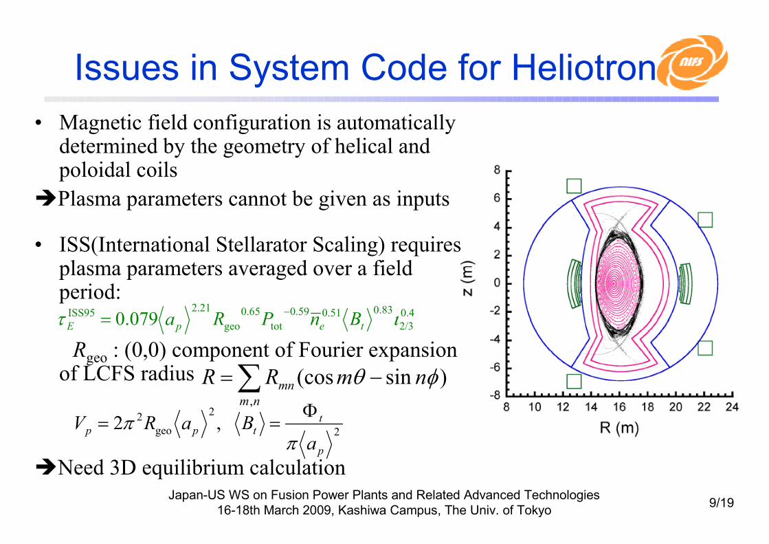
Issues in System Code for Heliotron
• Magnetic field configuration is automatically determined by the geometry of helical and poloidal coils
�Plasma parameters cannot be given as inputs
• ISS(International Stellarator Scaling) requires plasma parameters averaged over a field period:
Rgeo : (0,0) component of Fourier expansion of LCFS radius
�Need 3D equilibrium calculation
2
2
geo
2 ,2
p
ttpp
aBaRV
ππ
Φ==
∑ −=nm
mn nmRR,
)sin(cos φθ
0.4
2/3
83.051.059.0
tot
65.0
geo
21.2ISS95 079.0 ιτ tepE BnPRa
−=

Japan-US WS on Fusion Power Plants and Related Advanced Technologies
16-18th March 2009, Kashiwa Campus, The Univ. of Tokyo10/19
3. Consideration of Simplified Calculation
• Detailed calculation is needed for the parameters related to helical coil– Maximum field on coil Bmax→Magnetic field on confinement region Bt
(→Confinement performance)
– Coil shape (Rc, ac, m, …)→Magnetic surface configuration (Rgeo, <a>, amin) (→ confinement property, blanket placement)
– Coil shape → Stored magnetic energy Wmag (→ location of poloidal coil)
• They cannot be obtained by simple analytical formulae, but should be described by the geometry of helical coils
→ expected to be continuous functions of coil geometric parameters
• Can be calculated with an approximation formula or inter/extrapolation
Japan-US WS on Fusion Power Plants and Related Advanced Technologies
16-18th March 2009, Kashiwa Campus, The Univ. of Tokyo11/19
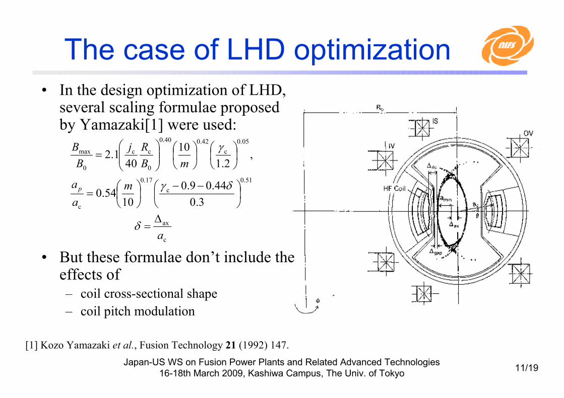
The case of LHD optimization
• In the design optimization of LHD, several scaling formulae proposed by Yamazaki[1] were used:
• But these formulae don’t include the effects of– coil cross-sectional shape
– coil pitch modulation
c
ax
a
∆=δ
[1] Kozo Yamazaki et al., Fusion Technology 21 (1992) 147.
51.0
c
17.0
c
05.0
c
42.040.0
0
cc
0
max
3.0
44.09.0
1054.0
,2.1
10
401.2
−−
=
=
δγ
γ
m
a
a
mB
Rj
B
B
p
Japan-US WS on Fusion Power Plants and Related Advanced Technologies
16-18th March 2009, Kashiwa Campus, The Univ. of Tokyo12/19
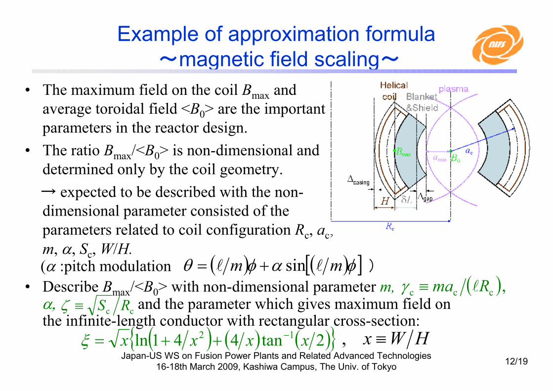
(α :pitch modulation )• Describe Bmax/<B0> with non-dimensional parameter m,
α, and the parameter which gives maximum field on the infinite-length conductor with rectangular cross-section:
Example of approximation formula
~magnetic field scaling~
• The maximum field on the coil Bmax and
average toroidal field <B0> are the important
parameters in the reactor design.
• The ratio Bmax/<B0> is non-dimensional and
determined only by the coil geometry.
→ expected to be described with the non-
dimensional parameter consisted of the
parameters related to coil configuration Rc, ac,
m, α, Sc, W/H.( ) ( )[ ]φαφθ mm ll sin+=
cc RS≡ζ
( ) ( ) ( ){ }2tan441ln 12 xxxx −++=ξ HWx ≡,
( ),ccc Rma l≡γ

Japan-US WS on Fusion Power Plants and Related Advanced Technologies
16-18th March 2009, Kashiwa Campus, The Univ. of Tokyo13/19
New scaling of magnetic field ratio
( ) 815.0796.00.156
c
853.0117.0
0
max 185.0 −−−+= ζξγα mB
B
8.005.0
c
82.0
05.0
c
42.040.0
0
cc
0
max
2.1
10
401.2 −−∝
= ζγ
γm
mB
Rj
B
B
Yamazaki’s scaling law [1]:
1.007.0
,2.02.0,21
,204),12,10,8( c
≤≤
≤≤−≤≤
≤≤=
ζ
αH
W
Rm
*Presented at 18th TOFE in San Francisco

Japan-US WS on Fusion Power Plants and Related Advanced Technologies
16-18th March 2009, Kashiwa Campus, The Univ. of Tokyo14/19
Calculation of vacuum magnetic field
• We need several parameters of
equilibrium magnetic field;
<ap>, Rgeo, amin, … etc.
• If two coils are similar to each
other, generated magnetic surface
configurations including ergodized
layer are also similar to each other.
• Database generated by the
calculation with several points of γc, α, ζ, W/H, Rax for baseline design
(e.g., Rc=10m, Ic=1MA) can yield
values (<ap>, amin, Vp, Rgeo, Φt) by
inter/extrapolation.
FFHR-2m1:
Rc=14m
1/2 scale:
Rc=7m,
dimension:1/2
current:1/4
Japan-US WS on Fusion Power Plants and Related Advanced Technologies
16-18th March 2009, Kashiwa Campus, The Univ. of Tokyo15/19
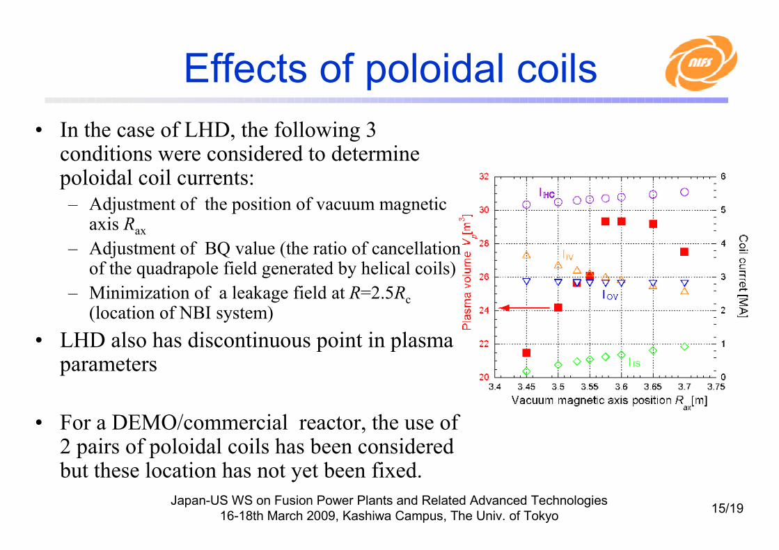
Effects of poloidal coils
• In the case of LHD, the following 3 conditions were considered to determine poloidal coil currents:– Adjustment of the position of vacuum magnetic
axis Rax
– Adjustment of BQ value (the ratio of cancellation of the quadrapole field generated by helical coils)
– Minimization of a leakage field at R=2.5Rc
(location of NBI system)
• LHD also has discontinuous point in plasma parameters
• For a DEMO/commercial reactor, the use of 2 pairs of poloidal coils has been considered but these location has not yet been fixed.

Japan-US WS on Fusion Power Plants and Related Advanced Technologies
16-18th March 2009, Kashiwa Campus, The Univ. of Tokyo16/19
Placement of poloidal coils
• The structure of equilibrium magnetic field is strongly affected
by location and current of poloidal coils.
Initially proposed
for FFHR-2m2:
RIV / ZOV= 12.8 / 22.1 m
ZIV / ZOV= 6.8 / 4.5 m
IIV / IOV= 14.7 / 17.9 MA
<a>=2.225m, Vp=1570m3
After modification:
RIV / ROV= 12.8 / 22.4 m
ZIV / ZOV= 8.0 / 5.4 m
IIV / IOV= 11.8 / 18.9 MA
<a>=2.465m, Vp=2050m3
Japan-US WS on Fusion Power Plants and Related Advanced Technologies
16-18th March 2009, Kashiwa Campus, The Univ. of Tokyo17/19
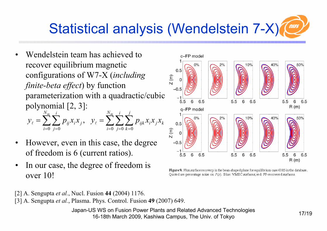
Statistical analysis (Wendelstein 7-X)
• Wendelstein team has achieved to
recover equilibrium magnetic
configurations of W7-X (including
finite-beta effect) by function
parameterization with a quadractic/cubic
polynomial [2, 3]:
• However, even in this case, the degree
of freedom is 6 (current ratios).
• In our case, the degree of freedom is
over 10!
[2] A. Sengupta et al., Nucl. Fusion 44 (2004) 1176.
[3] A. Sengupta et al., Plasma. Phys. Control. Fusion 49 (2007) 649.
∑∑∑∑∑= = == =
==mm N
i
i
j
j
k
kjiijk
N
i
i
j
jiij xxxpyxxpy0 0 00 0
,ll
Japan-US WS on Fusion Power Plants and Related Advanced Technologies
16-18th March 2009, Kashiwa Campus, The Univ. of Tokyo18/19
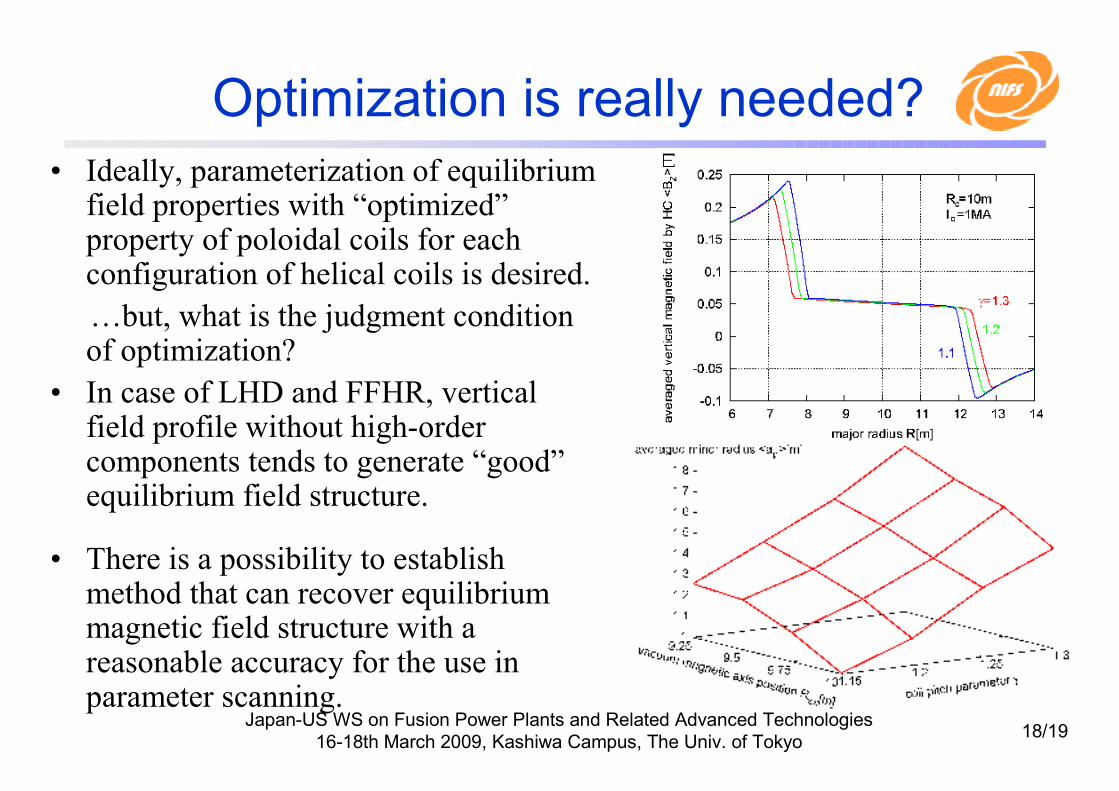
Optimization is really needed?
• Ideally, parameterization of equilibrium field properties with “optimized”property of poloidal coils for each configuration of helical coils is desired.
…but, what is the judgment condition of optimization?
• In case of LHD and FFHR, vertical field profile without high-order components tends to generate “good”equilibrium field structure.
• There is a possibility to establish method that can recover equilibrium magnetic field structure with a reasonable accuracy for the use in parameter scanning.
Japan-US WS on Fusion Power Plants and Related Advanced Technologies
16-18th March 2009, Kashiwa Campus, The Univ. of Tokyo19/19
4.Summary and future work
• System design code for heliotron reactors is being developed. Simplified calculation methods expected to enable sensitivity analyses over a wide design space.
• Immediate issue is to establish a method that can recover equilibrium magnetic field structure with a reasonable accuracy.
• To achieve high reliability, we will need to – improve liability in estimation of plasma performance by
� refining ISS scaling law (considering of dependence on magnetic axis shift and density / temperature profile)
�considering finite β effect
– develop a simple evaluation method for TBR, maintenance, and operation scenario.
• Operation regime with high robustness (that isn’t so much affected by a model ambiguity) is important for assured progress towards a commercial reactor, instead of the (locally) optimized design point.
Japan-US WS on Fusion Power Plants and Related Advanced Technologies
16-18th March 2009, Kashiwa Campus, The Univ. of Tokyo20/19
Other Items to be considered
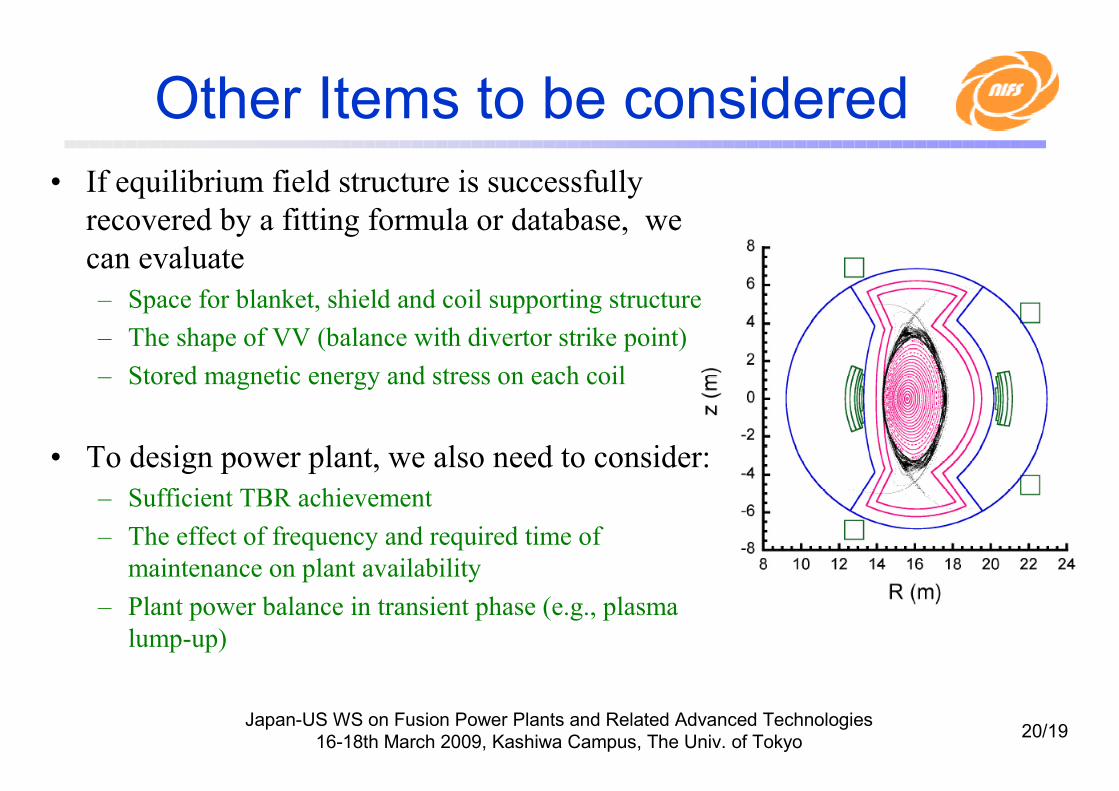
• If equilibrium field structure is successfully
recovered by a fitting formula or database, we
can evaluate
– Space for blanket, shield and coil supporting structure
– The shape of VV (balance with divertor strike point)
– Stored magnetic energy and stress on each coil
• To design power plant, we also need to consider:
– Sufficient TBR achievement
– The effect of frequency and required time of
maintenance on plant availability
– Plant power balance in transient phase (e.g., plasma
lump-up)

Japan-US WS on Fusion Power Plants and Related Advanced Technologies
16-18th March 2009, Kashiwa Campus, The Univ. of Tokyo21/19
Placement of poloidal coils
• The location of poloidal coil (PC) needs to be fixed to carry out equilibrium magnetic surface.
• PC current is determined by dipole component (BD) and quadrupolecomponent (BQ).
• Magnetic field generated by helical coil can be calculated by inter/extrapolation of tabulated data with sufficient accuracy.
-55.150-515.731.2272-0.29960.55116linear
extrapolation
-55.140-515.621.2273-0.29980.55277γc=1.5, ζ=0.06, W/H=2.2
-54.431-508.151.2356-0.32800.58954linear
interpolation
-54.428-508.121.2357-0.32770.58939γc =1.25, ζ=0.15W/H=0.095
Bz(@5Rc)
[Gauss]
Bz(@2.5Rc)
[Gauss]
Bz(R=0)
[T]
BQ
[T/m]
BD
[T]
Table: Magnetic field generated by helical coil with Rc=10m. Ic=1MA
Japan-US WS on Fusion Power Plants and Related Advanced Technologies
16-18th March 2009, Kashiwa Campus, The Univ. of Tokyo22/19
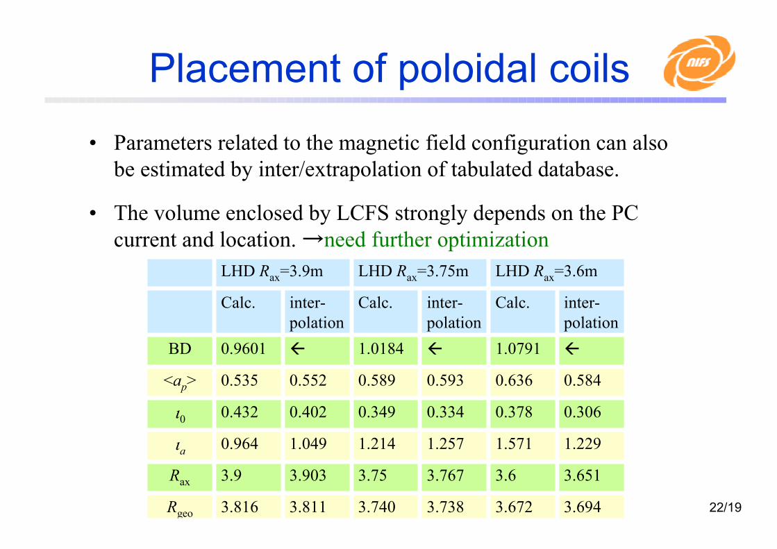
Placement of poloidal coils
• Parameters related to the magnetic field configuration can also
be estimated by inter/extrapolation of tabulated database.
• The volume enclosed by LCFS strongly depends on the PC
current and location. →need further optimization
LHD Rax=3.6mLHD Rax=3.75mLHD Rax=3.9m
Rgeo
Rax
ιa
ι0
<ap>
BD
3.6943.6723.7383.7403.8113.816
3.6513.63.7673.753.9033.9
1.2291.5711.2571.2141.0490.964
0.3060.3780.3340.3490.4020.432
0.5840.6360.5930.5890.5520.535
1.07911.01840.9601
inter-
polation
Calc.inter-
polation
Calc.inter-
polation
Calc.