determination of wave loads for ship structural analysis b
TRANSCRIPT

Aft-010-315-
Determination of Wave Loads for Ship Structural Analysis
B.P. Phelps
DSTO-RR-0116
APPROVED FOR PUBLIC RELEASE
© Commonwealth of Australia
DTIC QUALITY iUbPEOTJSD 3
DEPARTMENTOF DEFENCE
DEFENCE SCIENCE AND TECHNOLOGY ORGANISATION
Determination of Wave Loads for Ship Structural Analysis
B.P. Phelps
Maritime Platforms Division Aeronautical and Maritime Research Laboratory
DSTO-RR-0116
ABSTRACT
The adequacy of a structure can only be realistically determined if it is assessed with sound knowledge of the loads that are likely to be applied to that structure. Therefore, methods for evaluating hydrodynamic loads on ships have been reviewed in order to assess their applicability to RAN ships. The different methods are used at various stages of design or analysis dependant upon the amount of time and information available to the designer/analysist. Methods for calculating still water loads and wave bending loads using the Static-Balance method are outlined and comparisions of the methods provided. The use of Strip Theory methods to determine the probable and design extreme amplitude shear force or bending for a particular sea state is explained and predictions are compared with full scale measurements. Methods for long term load predictions such as Adamchak's Method and load shortening curves are also discussed. Methods for applications of these loads to finite element models are given and the particular case of an analysis of an RAN ship is discussed.
RELEASE LIMITATION
Approved for public release 19980430 149 DEPARTMENT OF DEFENCE ♦
DEFENCE SCIENCE AND TECHNOLOGY ORGANISATION
DTIC QUALITY INSPECTED 3

Published by
DSTO Aeronautical and Maritime Research Laboratory PO Box 4331 Melbourne Victoria 3001 Australia
Telephone: (03)9626 7000 Fax: (03) 9626 7999 © Commonwealth of Australia 1997 AR-010-375 November 1997
APPROVED FOR PUBLIC RELEASE
Determination of Wave Loads for Ship Structural Analysis
Executive Summary
The adequacy of a structure can only be realistically determined if it is assessed with sound knowledge of the loads that are likely to be applied to that structure. At the request of the task sponsor, methods for evaluating hydrodynamic loads on ships have been reviewed in order to assess their applicability to RAN ships. It is generally accepted, that both hydrostatic and self-weight loads can be determined for a given ship condition with a high degree of confidence. The evaluation of wave generated hydrodynamic loads, however, is less reliable and there is less guidance as to how to handle the dynamic nature of the loading as well as transient effects such as slamming.
A review of wave load calculation methods and their application to finite element models has been conducted and where possible, evaluated using experimental data. Different formulae for the traditional design 'static wave1 height are presented together with background information as to their application. Alternatively, strip theory may be used to predict wave loads on ships in different sea states, ship speeds and headings. A probabilistic assessment then enables the probable maximum load for the given sea state to be predicted and if all combinations of ship speed, heading and sea state are considered, long term design extreme and fatigue loads can be evaluated. The accuracy of the strip theory and other codes has been investigated by several researchers, including the author, and it appears that the error associated with predicting midships bending moment using strip theory is of the order of 10% to 20%.
The ultimate bending moment is the extreme bending moment that is likely to be experienced by a ship in it lifetime, so methods for determining the ultimate bending moment are investigated. For RAN purposes, the most appropriate method at present appears to be that of Adamchak which is incorporated into the MAESTRO program. There is limited, albeit very encouraging, correlation between numerical predictions and test data and further evaluation is therefore recommended. The use of load shortening curves as a means for determining ultimate strength is briefly discussed, but suitable computer programs are required for effective use of this method. For quick, simplistic calculations, analytical methods provided by Hughes (1983) enable the minimum load to collapse stiffened panels to be determined.
It is recommended that further work be done to establish an appropriate procedure for the direct application of wave spectrum loads onto finite element models and to validate results obtained against alternative methods and full scale measurements. This would enable more realistic loading scenarios to be analysed with greater confidence and within a lesser period of time. This will benefit both the RAN acquisition process, by enabling more thorough investigation of structural strength, and fleet support program by providing greater knowledge of loads which may cause failure of structures.

Author
B.P. Phelps Maritime Platforms Division
Bernie Phelps commenced a cadetship with the Department of Defence in 1984 and graduated from University ofN.S.W. with B. Eng Naval Architecture (Hons) in 1986. He then went on to complete a MSc. (Naval Architecture) degree at University College London, graduating in 1988. He was employed with the Directorate of Naval Architecture in Canberra in 1987 and 1989. From late 1989 until April 1992 he was the Hull Liaison Engineer with the RAN New Submarine Project in Malmö, Sweden. In mid 1992 he started with the, then, Materials Research Laboratory analysing results of hydrodynamic loads trials on RAN ships and analysis of submarine structures. He now conducts analysis and numerical modelling of hydrodynamic loads and ship's structural responses.
Contents
1. INTRODUCTION 1
2. LOAD CALCULATION METHODS 2 2.1 Still Water Loading 2 2.2 Static-Balance Method 3
2.2.1 Design Wave Height for Static-Balance Method 4 2.3 Strip Theory Methods 8
2.3.1 Short Term Design Loads from Strip Theory 10 2.3.2 Long Term Design Loads from Strip Theory 13
2.4 Three-Dimensional Methods 15
3. ULTIMATE BENDING MOMENT 15 3.1.1 Adamchak's Method 16 3.1.2 Load Shortening Curves 17 3.1.3 Panel Collapse as a Criteria for Hull Failure 18
4. APPLICATION OF LOADS USING FINITE ELEMENT ANALYSIS 19 4.1 General Approach to Ship Structural Modelling 19 4.2 Static and Static-Balance Load Cases 20 4.3 Wave Spectrum Load Case 22
4.3.1 Analysis of the RAN LST/THSS 22
5. CONCLUSIONS AND RECOMMENDATIONS 23
6. NOTATION 25
PREFERENCES 27

DSTO-RR-0116
1. Introduction
It is generally accepted for the purposes of ship structural design and analysis, that both hydrostatic and self-weight loads can be determined for a given ship condition with a high degree of confidence. The underwater shape of the hull is readily determined from detailed knowledge of the hull offsets and appendages, enabling the buoyancy distribution to be calculated through Archimedes principle. Detailed weight lists, including knowledge of stores, cargo and fuel, enable the self-weight distribution to be calculated. The application of these loads to a finite element model for analysis is relatively straight forward since the loads are static, well defined and are easily applied as pressure or self-weight load types available within finite element programs.
The evaluation of wave generated hydrodynamic loads, however, is less reliable than the static loads and there is less guidance as to how to handle the dynamic nature of the loading as well as transient effects such as slamming and sloshing. In the past four to five decades, research has provided increased knowledge of the nature of hydrodynamic loads, which together with the improvements in electronic computers, have greatly enhanced the capability to determine the effects of these loads on ship structures. The work of people such as St. Denis and Pierson (1953), Korvin- Kroukovsky (1955), Korvin-Kroukovsky and Jacobs (1957) and Salvesen et al(1970) have provided the basis for the mathematical description of hydrodynamic loads on ships. These methods are essentially linear and two-dimensional in nature and although reasonably accurate for moderate sea conditions and ship speeds, they are less accurate for extreme loading conditions which are also the most critical when considering hull structural strength. Non-linear theories (Ochi and Motter, 1973, Belik et al, 1983) and three-dimensional loads prediction methods such as PRECAL1 have been introduced but these require greater computational effort and have not yet proven to be significantly more accurate than the two dimensional methods.
The application of hydrodynamic loads to finite element models is also more difficult than for static load cases due to the dynamic nature of the problem as well as the loads themselves being less clearly defined. Many documents have been written in relation to various hydrodynamic loading theories and likewise on finite element analysis of ship structures and components, however the joint treatment of the two has not seen the same attention. It is the intention of this report therefore, to provide an outline of common methods used for determining hydrodynamic loads on ships, to provide guidance on their limitations and to discuss suitable procedures for applying these loads to ship structures through finite element analysis.
1 PRECAL is a linear, three-dimensional, frequency domain computer program for die prediction of hydrodynamic loads and was developed by the Netherlands Ship Model Basin Cooperative Research Ships organisation.

DSTO-RR-0116
2. Load Calculation Methods
A ship is a freely floating body on the surface of the water and so is subjected a combination of hydrostatic and hydrodynamic forces depending on whether either the ship or the free surface are moving. At the overall or global level, if the ship is considered as a rigid body (a beam or girder), then Newton's second law must be satisfied. That is:
->■
-+ 8(mv) ~* m F = — = m a (1) 5t
An exact analytical solution however is not yet possible except in the hydrostatic case, where a = 0. The simple hydrostatic case where both the ship and the water are still is referred to as the 'still water' case and is the starting point for almost all hull strength calculations.
2.1 Still Water Loading
When a ship is floating at rest in still water, for equilibrium the total net force and moment on the ship is zero. The shear force and bending moment distribution on the ships are then given respectively by the integration of the difference between the weight and buoyancy, and their resultant moment, along the length of the ship. That is;
Shear Force: J{w(x) - b(x)}dx = 0 -L/2
1/2
Moment: |x. {w(x) - b(x)}dx = 0
L" (2) t/2 v '
-L/2
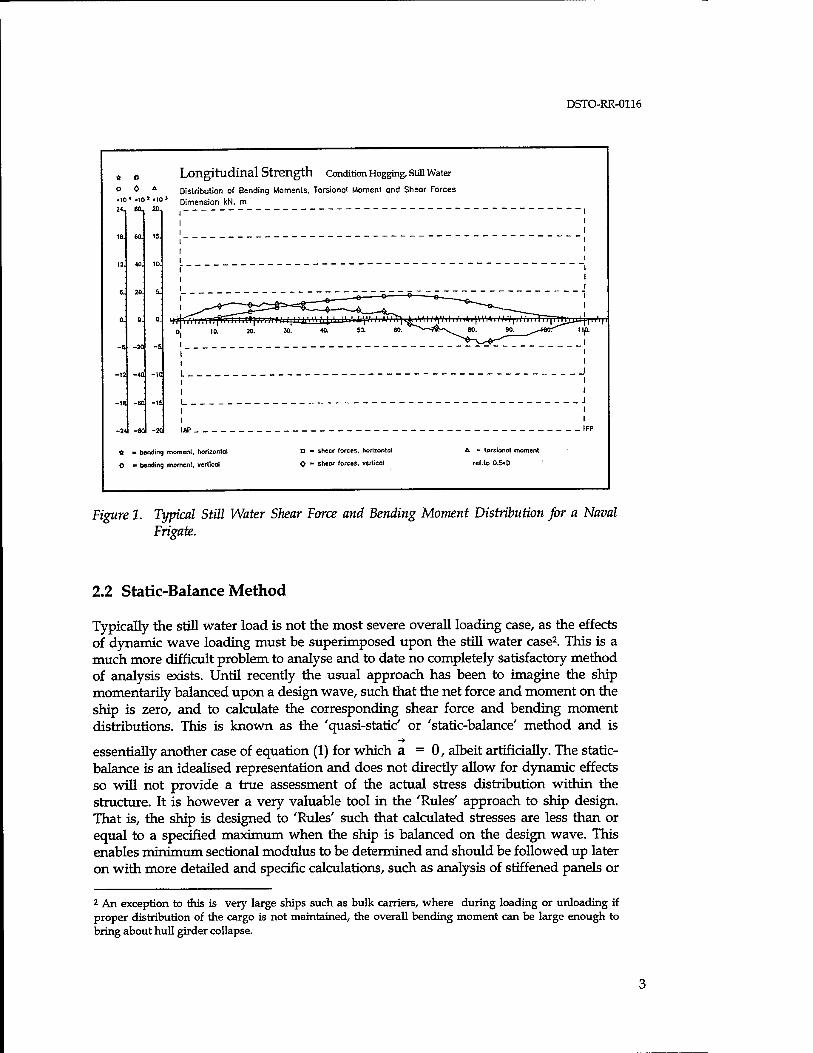
The shear force and bending moment information is usually illustrated graphically for given load conditions as shown in Figure 1. Often, only the vertical bending case is considered, as this is by far the most significant still water load case, but for SWATH's (Small Waterplane Area, Twin Hull) and other multihull vessels it will also be necessary to consider the transverse distribution of weight and buoyancy for the cross deck structure calculations.
DSTO-RR-0116
* „ Longitudinal Strength Condition Hogging, Still Water ° * * Distribution of Bending Moments. Torsional Moment and Sheor Forces .10'.io»MO* Dimension kN. m
80- 20,
18. CO. 15.
12. 40. 10.
e. 20. 5.
0. 0. 0.
-6. -20 -s.
-12 -40 -IC
-18 -EC -15
-2* -80 -2C
nTp
6 ■ bending moment, horizontal
O ■ bending moment, vertical
D ■> shear forces, horizontal
<> - sheor forces, vertical
A - torsional moment
ref.to 0.5>D
Figure 1. Typical Still Water Shear Force and Bending Moment Distribution for a Naval Frigate.
2.2 Static-Balance Method
Typically the still water load is not the most severe overall loading case, as the effects of dynamic wave loading must be superimposed upon the still water case2. This is a much more difficult problem to analyse and to date no completely satisfactory method of analysis exists. Until recently the usual approach has been to imagine the ship momentarily balanced upon a design wave, such that the net force and moment on the ship is zero, and to calculate the corresponding shear force and bending moment distributions. This is known as the 'quasi-static' or 'static-balance' method and is
essentially another case of equation (1) for which a = 0, albeit artificially. The static- balance is an idealised representation and does not directly allow for dynamic effects so will not provide a true assessment of the actual stress distribution within the structure. It is however a very valuable tool in the 'Rules' approach to ship design. That is, the ship is designed to 'Rules' such that calculated stresses are less than or equal to a specified maximum when the ship is balanced on the design wave. This enables minimum sectional modulus to be determined and should be followed up later on with more detailed and specific calculations, such as analysis of stiffened panels or
2 An exception to this is very large ships such as bulk carriers, where during loading or unloading if proper distribution of the cargo is not maintained, the overall bending moment can be large enough to bring about hull girder collapse.

DSTO-RR-0116
deck openings. Calculated stresses using the design wave approach may be used for comparison purposes throughout the life of the ship, for example, to determine the effects of major structural modifications, but it should always be recognised that calculated stress level are indicative only. It is generally considered that this approach is conservative in terms of overall hull girder strength, and according to Kamel and Lui (1971), work by Lewis (1957) and Jacobs (1958) has shown that bending moments predicted by the static-balance method are greater than those calculated from solutions to the equations of motion.
The weight and 'static wave' buoyancy distributions are needed to determine the shear force and bending moment distribution along the length of the ship. The ship is typically broken down into at least twenty sections for these calculations. The weight distribution usually comes from design calculations and the buoyancy distribution is calculated through an iterative procedure. To calculate the buoyancy distribution, the waterline takes on the shape of the assumed wave profile (usually trochoidal) of height H and of length X, which is most commonly taken as A. = LBP although sometimes X = 0.9 LBP may be used, as for example, the case presented in Figure 2. With the crest (hogging case) or trough (sagging case) of the wave at midships, the trim and the submergence of the ship are iteratively adjusted until the force and moment equations (Equations 3) are balanced.
L/2 Shear Force: £ {w(Xi)-b(x£)}8x = 0
-L/2
i = l,...no of stations (3) L/2
Moment: £ xi.{w(xi)-b(xi)}8x =0 -L/2
Once these equations are balanced, the shear force and bending moment distributions are determined through integration of the sectional forces along the hull, as for example shown in Figure 2. The resulting load distributions may be applied to a finite element model in a number of ways as discussed in section 4.2.
2.2.1 Design Wave Height for Static-Balance Method
There has been much discussion as to suitable methods for specifying design wave height, and historical accounts of standard wave height formulae are given by Evans (1975) and in SSCP23. Probably the most common formula are:
i. H = L/20, although this is less commonly used nowadays, particularly for higher wave lengths,
Ü. The H = 1.1 VT (feet) or H = 0.6VT (metres), iii. The'8m'wave3 given by
3 An increase of 15% is recommended if the ship operates solely in the North Atlantic. (SSCP23)

DSTO-RR-0116
H = — m ; L < 80m 10 8 m ; L > 80m.
(4)
The increase in design wave height with length L for the three methods are shown in figure 3.
Longitudinal Strength Static Wave Balance, Hogging Condition Wave Amplit = 5.2 m, Wove Height =0.9 LBP, Direction = 0deg.
00 Distribution of Bending Moments, Torsional Moments Wave Crest at 45.0 m. Ship Speed = 25 knots 00« .10» .101 & sheaI Forces. Dimensions kN, m 24, B0_ 20,
' bending moment, horizontal
.bending moment, vertical
D - shear forces, horizontal
^ * shear forces, vertical
k - torsional moment
ref.to O.5«0
Figure 2. Typical Hogging Force and Moment Distributions for a Naval Frigate
Inherent in the use of these formulae are assumptions as to how they should be applied and these must be considered when these methods are used. For example, it in
the use of the O.öVL for design purposes, it is intended that the bare hull, with the superstructure being considered structurally ineffective, be used in calculations of maximum bending stress (Sikora et al)4. It must be remembered to include the superstructure in subsequent calculations to ensure adequacy of the superstructure. The 8m wave is based upon comparisons with extensive trials results (Clarke 1985 and
1986) and is recommended by SSCP23 for design purposes. Since the 0.6-V/L wave allows for the increase in effective wave height with ship length while acknowledging the non-linear manner of this increase, it may be more appropriate for design of larger ships (above about 200m). For typical naval vessels such as frigates, the 8m wave more
4 Table 4.1 of NAVSEA (1976) suggests that if the superstructure is "long" it may be included in the longitudinal bending calculations, however the need to apply "stringent rules" relating to the effectiveness of longitudinal elements is stressed.

DSTO-RR-0116
appropriate as it has been derived from trials results of vessels of this type. Regardless of which ever method is used, the need to ensure that the methods are applied correctly as outlined in the appropriate manuals (SSCP23, NAVSEA) is stressed.
400 500
Length, L (m)
Figure 3. Comparison of Design Wave Height Formulations.
For preliminary design, if detailed information of the mass distribution along the ship is not known, then it will be necessary to estimate a worst case design wave bending moment at the midships section using formulae such as the dimensional expression provided by SSCP23 developed from at-sea strain measurements;
M,
M wh
= (gAL /100)(9.0 - 0.02L -0.5*10"4L2)
= (gAL /100)(3.0 + 0.02L -1.1*1(T4L2) (5)
where; g is in m/s2, A is displacement in tonnes (including margins and through life increases), L is in meters and bending moments are in units of (gAL). A "(1-cos2)" distribution5 of bending moment be used to extend the midships bending moment to cover the full length of the ship, as shown in figure 3 and the still water bending moment must be added to provide the overall bending moments.
Bending moments calculated using any of the above formulae are intended to provide expected values of maximum bending moments likely to occur once in the life of the ship (3 x 10⁷ wave encounters in the case of the 8m wave) and so resulting bending
moments must be factored to provide a safe design limit. In the case of the 0.6VL
5 This may also be referred to as the (1-cos) distribution due to the identity;
1 - cos2 0 = (l-cos20)/ 2 where 0 = 7tx/L.

DSTO-RR-0116
wave a factor of Ly=2.0 is used by the RAN (Thomson), whereas to achieve a 1%
probability of exceedance of the expected wave bending moment, SSCP23 recommends that the wave bending component of the 8m wave be multiplied by L f =1.54. The design bending moments for hogging and sagging are then given by:
Mds = Msw + L7(MS - Msw)
= Msw + L;(Mh - Msw) M (6)
where Ms and Mh are calculated using the static-balance method. These expressions may be used to calculate the bending moment distribution along the full length of the
ship.
To allow for the effects of slamming and whipping, Clarke (1986) recommends that the midships bending moment value be carried forward to 0.35L from the forward perpendicular and from there to be reduced linearly to zero at the forward perpendicular, as shown in Figure 4. Recent work by Phelps and Boyd (1997) suggests that similar consideration should be given to allowance for stern slamming. Trials results show that measured bending moments in moderate seas are very close to the (1-cos2) distribution with one percent probability of exceedence in moderate conditions and so are likely to be exceeded in the event of stern slamming. An extension of the maximum bending moment to 0.6L followed by linear reduction to the aft perpendicular is suggested.
Sagging BM '1-cos2' distribution
Peak bending moment extended to include
slamming component
Figure 4. Design Vertical Bending Moment Distribution with Allowance for Slamming.
Finally, it should be recognised that the static balance method is only intended to provide the minimum scantlings needed for adequate structural strength and that more detailed calculations are required to ensure satisfactory in-service structural performance.

DSTO-RR-0116
2.3 Strip Theory Methods
The static-balance method provides a yardstick by which to assess the adequacy of existing or proposed designs but does not provide a realistic assessment of loads being imposed on a ship by a particular seaway. This means that they are not useful for a retrospective analysis where for example it may be necessary to assess the loads that caused damage to a structure, or alternatively to investigate the probable extreme load for a given sea state. This is a complicated task involving the estimation of dynamic and static pressures, inertia loads, added mass and damping effects, prediction of ship motions and then combining these to give the total load distribution over the ship. This type of analysis may be carried out using a combination of statistics and strip theory.
Strip theory is a linear superposition method which derives it's name from the technique employed whereby the ship is idealised as being made up of a series of prismatic sections, or strips. The three dimensional problem is therefore broken down into a series of two-dimensional problems where forces and motions of each strip can be solved independently and then integrated along the length of the ship to provide the response for the whole vessel.
Strip theory calculations are by necessity computer based and several strip theory programs are available for this purpose, such as SHIPMO (Graham and Millar, 1984, and McTaggart, 1993). Most strip theory programs are based upon the methods of Salvesen et. al.(1970), and are considered linear programs since they assume that:
i. An irregular seaway can be adequately represented by the linear summation of regular waves (sine waves), and
ii. Ship responses (motions and stresses) to regular waves are linear and so superposition may be used to determine the overall responses to an irregular seaway.
Important assumptions of strip theory programs are that of "wall-sidedness", that is, each strip is of constant section and sides of the ship are vertical above and below the still water line, and that wave heights are assumed small compared to the draft of the ship. The results of these assumptions are that:
i. Strip theory does not differentiate between hogging and sagging bending moments,
ii. Strip theory is not generally valid for application to multihulls as it assumes that the hull is continuous and symmetric about the fore and aft axis and there is no consideration of wave interaction between hulls6.
6 The hybrid strip theory program HYDROS (Doctors, 1993) has partly overcome this limitation using a panel or boundary-element method to define the strips and to calculate hydrodynamic coefficients which enables asymmetric hulls to be considered. Also, wave interaction between hulls in the same strip are accounted for by the program, but there is no consideration of waves generated by one strip interacting with waves generated by following strips. This is a speed dependent effect and to date it has not been possible to quantify this effect using strip theory programs.
DSTO-RR-0116
iii. Strip theory is a slender ship theory (L/B > 7) and is strictly valid only for low to moderate sea states,
iv. Calculation of strip theory hydrodynamic coefficients and forces are based upon the assumption that ship speed is relatively slow and so predictions deteriorate at higher Froude numbers (Fn>0.3 - McTaggart and Ando, 1992).
v. Slamming predictions are limited to pressures and forces derived from empirical form factors and relative velocities, although not all strip theory programs provide such calculations.
Based upon comparisons with onboard measurements from several Royal Navy (RN) ships, Clarke (1986) concluded that strip theory over-estimated wave bending moments, particularly at larger wave heights7. The hogging bending moment was over predicted more so than the sagging moment as the measured slam transient coincided with the sagging bending moment, increasing the measured bending moment to nearer those predicted by strip theory. It was concluded that strip theory over estimates the midships sagging bending moment by an amount approximately equal to the slamming contribution.
Some strip theory programs, such as DREA's time domain HYPOH2 program, provide predictions of hull surface pressures consisting of a hydrostatic component as well as time varying radiation and diffraction components. According to McTaggart and Ando (1992) however, validation against limited towing test data shows poor agreement and they suggest that strip theory does not provide sufficiently accurate predictions of hydrodynamic pressures for ship structural design. An exception to this may be the HYDROS program which uses the panel method with lid to avoid problems of irregular frequencies, which although it does not currently provide pressure explicitly, they are calculated internally by the program and it is believed that future development of this program will see nodal pressure data being made available.
A validation of three strip theory codes, and of the 3-D panel method code PRECAL (see section 2.4), was conducted by Dalzell et al (1992) where analytical results were compared with model test data for three ships. The conclusion was that at best the differences between analytical and experimental midships bending moment RAOs were within 10% to 20% at peak values of the RAOs. For lower levels of RAO values, the experimental data scatter was of the order of the RAO magnitudes and so no clear assessment of analytical accuracy was possible. It was also concluded that although analytical methods can provide intelligent engineering estimates elsewhere than midships, quality of these estimates degrades towards the ends of the ship. The accuracy of the strip theory codes was degraded in bow and quartering seas particularly in the region between 60 degrees and beam on. These conclusion are supported results obtained by Phelps and Boyd (1997) when comparing full scale trials results with strip theory predictions.
7 As a guide, from data provided by Clarke it would appear that for midships bending moment, these non-linearities are most significant at wave heights greater than L/10, however results are also influenced by ship's speed and the reference should be consulted.
DSTO-RR-0116
Complicated time domain computer software has been developed to simulate ship's responses to slamming (e.g. Belik et al, 1983), but to obtain good statistical estimates of extreme responses very long computer simulations are required to enable phase angles between regular wave components to be sufficiently varied for the simulations. It has been found that large differences in extreme values can occur depending on the phase relationships (Clarke, 1986) and so predictions of long term slamming statistics are generally not possible at the present time due to limitations on simulation time. As a result, allowance for slamming in design calculations is often still very approximate, such as the extension of midships bending moment forward to 0.35L as described above.
2.3.1 Short Term Design Loads from Strip Theory
In fully developed seas it is generally held that the statistics of the seaway remain essentially constant (stationary) for a period of time lasting from about one hour up to 10 hours. The loads arising from such short duration seaways are known as short term loads and these are considered in this section.
Strip theory calculates the linear frequency response function8, H<^ (coe) between the
ship response and the wave spectrum. This is a complex relationship between the Fourier transforms of the input (wave, £,(coe)) and output (response, 9*(©e))
functions and is given by,
*K) =H^(coe).C(coe) (8)
It is to understood that either the real or the imaginary part only is being considered, not both.
The ship responses to a particular seaway are dependant upon loading condition, speed and relative wave heading as well as the actual encountered sea conditions. The relationship between wave frequency and encounter frequency is defined by these parameters as,
coe =co - (co2 / g)Vs cosy (7)
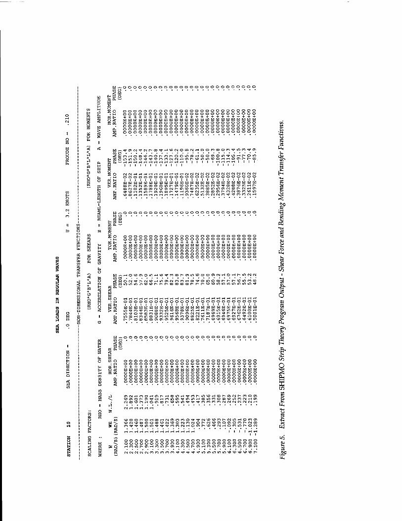
Typically, 'responses' provided by strip theory are; the amplitude ratio and phase angle between the discrete frequency components of the wave amplitude spectrum, and the acceleration, shear force or bending moment spectra, as for example the SHIPMO output given in Figure 5.
! Sometimes erroneously called the transfer function, as, for example in SHIPMO.
10
o z w D O
§
CO Ei O z
U z D ta 03 H Cu CO Z
H
01
CO
Z W s o s Da o
o 03
CO e3 «: w re CO
03 O h
CO OS o E-i O
s
►H-
o CO
s
a z o
CO
* s H
en
S Ed s H
o 33 03
o o 9 u a
i «;
rl H z ii Hi a ü
z a
w o3 W SB 3
OS EH
^OOOOOOOOOOOOOOOOOOOOOOOOOO u w a
z a w s o s o
• M 03 E-
oooooooooooooooooooooooooo oooooooooooooooooooooooooo ++++++++++++++++++++++++++ oooooooooooooooooooooooooo oooooooooooooooooooooooooo oooooooooooooooooooooooooo oooooooooooooooooooooooooo
^srcfiMTMi^tD^HVocMocoNHoorocoon^inroq'm o HmrHOCo^mor^Por-ooificoi-HoocTiOLn^rmtHr-om QLnii^io<3"^,^,,g,rorocMCNjrHcrtr^^DiotnvpotHiHOC^i^[^OD — HririHriHriHriHrid I I I I I ItHWrHrHI I I I
I I I I I I I I I I I I I I I I
CM CM rH O O O
I I I a ta H <o r~ CM CD CM O ■3* *£> »H \D CO H
HHHHHHHHHNWWNNCMMtMCMCMNCNCMCM OOOOOOOOOOOOOOOOOOOOOOO
I I I I I I I I I I I I I I I I I I I I I I I HHWHWHWwwHWWHHwwtawcaHsacaia CMcriCDOOir)r^<rivi>or^incMmcM,i'TCocoy>m*Hr^ incococM^ocriCMr^c^^conrocommcrtcMoor^cMfHCT» ninr^o\oicor^*?Hn^WHcococrit^oiojcoroy3Ji THT-ttHiHrHiHrHr-lWCTJI^^)ir)rOCNCMrO^,'t3,rorOCMtH
-oooooooooooooooooooooooooo
Ed CO < 33
03 04 rt w s CO O
• H 03 EH
oooooooooooooooooooooooooo oooooooooooooooooooooooooo ++++++++++++++++++++++++++ HHWHHWHWHHWWHHWWWHWHHWHKlfclH oooooooooooooooooooooooooo oooooooooooooooooooooooooo oooooooooooooooooooooooooo oooooooooooooooooooooooooo
y.HOlD010ifiHlß<!rnODM^inU)00(r>C>JHOHMf)C>I(N] o WON^p-fsHOHino'XMncoHOO'a'omoosr-r-i^vDiomoD QlOlOlnl/)VD>^[^^^r•oooococor•r*■^,*vDvi>lJ^lOlOl^l^lnln'l3,
03 CO u W KC W H EC Q * 03 Ou -' p: rt
65 lu X o co O
■ M X 03 EH EH H gg CO z & Q §
& Q
tHt-lTHtH»H<HrHtHiHiHiHTHrHiHrHrHrHtHTHWiHrHrHTHtHi-C oooooooooooooooooooooooooo
I I I I I I I I I I I I I I I I I I I 1 I I I I I I
^^rovnHODNifiVDcocDVDinHHr-oiinvDinr-CNiojOH in^o^a3rno30QCN]rHVor^mojcv]rHco,^»H^t^cs]VD<^oo r^r^cooooDCDcy\m<rt<TiCTiai<J\oooor-r-^D^D,x>vc>vDW3'i>v£>in
-oooooooooooooooooooooooooo
oooooooooooooooooooooooooo oooooooooooooooooooooooooo ++++++++++++++++++++++++++ oooooooooooooooooooooooooo oooooooooooooooooooooooooo oooooooooooooooooooooooooo oooooooooooooooooooooooooo
ff\NHfooHO^r'HoomH<3,ror'mw>Hoor*^Nr-nooi voi^o>^'3,HHmiooi'Tt3MnHODir)noiX)«>infO(NHO, cvjro^DroiHOc^oor^^inu^^^'ipfnfororoojcNiCNiojcvjojiH
i^oor-OrHcoTHCN^nno^^rcM^^Dfor-CNiniHoro^ *x>oj'x>coooaDVDc*)^oocNjrocMor-CN'*D^oa\oror-CMco on^^r^lf)u^^r«3,"3,rorotNitHO<^r--vD*a,cvi.-iOfOLnr-ooj
oooooooooooooooooooooooooo oooooooooooooooooooooooooo Hfoif)r>cj.Htr)ir)i^o^Hnmr-oiHroiOhcriHroinp*<jiH

DSTORR-0116
The frequency response function also provides the relationship between the wave height and response spectra. The amplitude ratio9 provides the linear relationship between the wave and response spectra at the various frequencies and is given by the modulus of the frequency response function. The phase angle is the angle by which the maximum value of the response, at that frequency, leads or lags the maximum value of the wave elevation at the wave origin.
In the SHIPMO program for example, the wave origin is located at the ship centre of gravity and a positive phase angle represents the response leading the wave elevation. The numerical value of the phase angle is given by the argument of the frequency response function, i.e. the arc-tangent of the ratio of the imaginary to real parts. That is:
2 = Sft(a)e) *** |Sc((De) (8)
Amplitude Ratio = |H<„c(coe)| = ^H^ + Ht
Phase Angle = arg[H^(coe)] = tan'^H^g/H,.^)
Therefore, with the frequency response function at each station provided by strip theory, for a given wave spectrum the corresponding acceleration, shear force and bending moment spectra at each station may be determined. By assuming a Rayleigh distribution of short term peak values, i.e. for a particular sea condition, useful statistics of these spectra may be obtained10:
Tz = average zero-upcrossing period in seconds 2n V(mn/m2)
^a = average amplitude
1.25Vmo
C,k = probable extreme amplitude (Ochi, 1978) for the particular sea state
C^ = design extreme amplitude for the particular sea state
H^K-Kif^ 9 The square of amplitude ratio is often referred to as the Response Amplitude Operator, or
RAO. 10 As the relationship between response spectrum and wave spectrum is linear, these formulae may be applied to either the waves or the ship's responses through appropriate choice of mn.
12
DSTO-RR-0116
where
T = duration of the specified sea, in hours a = a risk parameter, (e.g. a=0.01 means a 1% risk of exceeding the design value) k = total number of wave encounters for the particular sea state
n f QnS (ö)-d(ö = n'th moment of the spectrum in question
m.
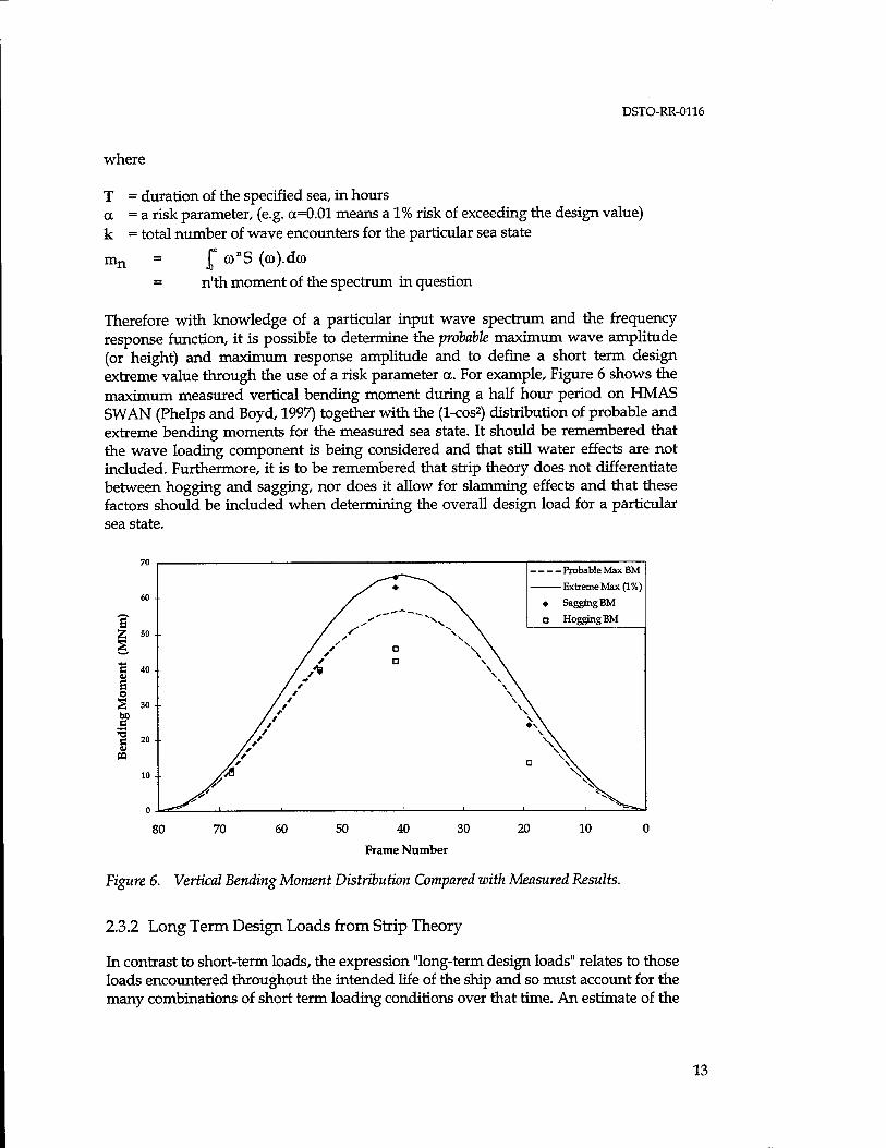
Therefore with knowledge of a particular input wave spectrum and the frequency response function, it is possible to determine the probable maximum wave amplitude (or height) and maximum response amplitude and to define a short term design extreme value through the use of a risk parameter a. For example, Figure 6 shows the maximum measured vertical bending moment during a half hour period on HMAS SWAN (Phelps and Boyd, 1997) together with the (1-cos2) distribution of probable and extreme bending moments for the measured sea state. It should be remembered that the wave loading component is being considered and that still water effects are not included. Furthermore, it is to be remembered that strip theory does not differentiate between hogging and sagging, nor does it allow for slamming effects and that these factors should be included when determining the overall design load for a particular sea state.
Probable Max BM
Extreme Max (1%)
• Sagging BM
D Hogging BM
80 70 60 50 40 30
Frame Number
20 10
Figure 6. Vertical Bending Moment Distribution Compared with Measured Results.
2.3.2 Long Term Design Loads from Strip Theory
In contrast to short-term loads, the expression "long-term design loads" relates to those loads encountered throughout the intended life of the ship and so must account for the many combinations of short term loading conditions over that time. An estimate of the
13

DSTO-RR-0116
long term design bending moment (often referred to in this context as the extreme lifetime bending moment) and the development of a fatigue loading spectrum based on probabilistic methods may also be made with the help of strip theory calculations.
The lifetime distribution of loads on a ship is going to be influenced by, amongst other things, ship's speed, heading, loading and environmental conditions. In order to determine the long term, or lifetime, design bending moment it is necessary to calculate RAOs which take into account these factors. Headings, speeds and loading conditions are ideally obtained through analysis of past fleet practices or operational analysis, while the probability of encountering various sea states may be obtained from wave scatter diagrams. A summation of responses, weighted by the probabilities of each combination of parameters, enables the fatigue load spectrum to be determined. A full outline of such method is provided by Sikora et al (1983), and a pictorial representation of this procedure is given in Figure 7 (Phelps, 1995/B).
As strip theory does not directly calculate slamming responses, empirical corrections are applied to determine extreme bending moments in hogging and sagging, for example as detailed by Sikora et al.
WAVE STATISTICS FROM
WAVE ATLASES
OPERATIONAL ANALYSIS
HULLFORM GEOMETRY
LONG TERM SEA STATE
PROBABILITIES - HS,T
SHIP SPEED - Vs
REL DIRECTION - <f LOAD CONDITION - A
STRIP THEORY - RAOs
Responses to each wave height/period combination weighted by probability of
ship condition
S„(G>,) = RAO.St(co)
LIFETIME ULTIMATE WAVE LOAD
WAVE FATIGUE LOAD SPECTRUM
CORRECTION FOR STILL WATER LOADS AND SLAMMING EFFECTS
LIFETIME ULTIMATE LOAD
LIFETIME FATIGUE LOAD SPECTRUM
Figure 7. Long Term Design Load Evaluation Using Strip Theory.
14
DSTO-RR-0116
2.4 Three-Dimensional Methods
Three-dimensional methods use what is known as the panel method to describe the hull shape of a vessel, that is the surface of the hull is approximated by a number of discrete panels. It is applicable to both monohull and multihull configurations and the restriction of slender ships no longer applies, thereby overcoming principal disadvantages of strip theory. Three-dimensional potential flow theory is used to calculate the fluid forces enabling ship motions and wave loads to be determined. Both time and frequency domain codes are available.
The NSMB Co-operative Research Ships developed code, PRECAL, is a frequency domain code which uses a three-dimensional Green function method to calculate the radiation and diffraction pressures. Either an exact speed-dependent form or a simplified Green function may be used, with large variations in CPU time as a result. McTaggart and Ando (1992) quote variations between 5 hours (exact) and 3 minutes (simplified) for a destroyer model using 227 panels, with no clear preference for either form being given. Ando (1995) presents a comparison of model test results with predictions from PRECAL for a 121.3 m destroyer in regular head seas. He concluded that predictions for heave and pitch motions, and vertical shear and bending moments at midships were quite good at moderate Froude numbers (Fn<0.29), but that pressure predictions were inconsistent for non-zero speed cases. By contrast, according to Dalzell et al (1992), when compared to model test results those from PRECAL were at times inconsistent, particularly at zero speed where they should have been better than strip theory, but yielded the best estimates in quartering and following seas.
From these conclusions there seems to be little evidence to suggest that the extra computational effort required by the three-dimensional codes such as PRECAL is warranted for conventional monohulls in moderate conditions. However, three- dimensional codes provide great potential in their ability to predict hydrodynamic loads for ships, particularly in relation to multihulls and for their ability to calculate nodal pressures for direct application to finite element models. It is likely, therefore, that further developments of three-dimensional codes can be expected in the future, both in their accuracy and their execution time, which will eventually see these codes replace the two-dimensional strip theory codes.
3. Ultimate Bending Moment
If the ship hull girder is progressively loaded through bending, the relationship between the bending moment and the curvature <f> is linear until individual structural members are no longer able to elastically carry further load, and through plastic deformation or buckling, begin to shed their load onto adjacent members. Under further loading, there will be progressive failure of individual structural members until such time as the hull is unable to carry further load. The bending moment at which this occurs is known as the Ultimate Bending Moment, M„, and as shown in
15
DSTO-RR-0116
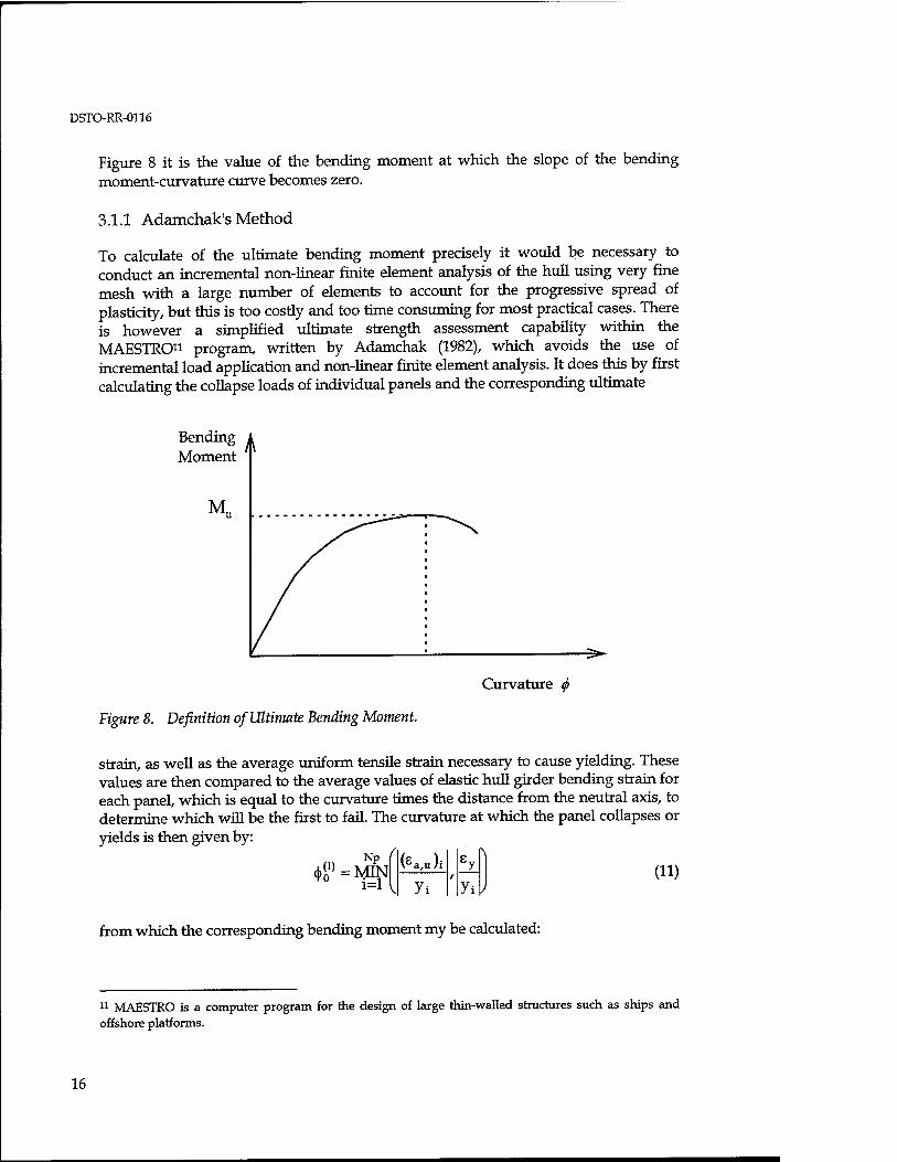
Figure 8 it is the value of the bending moment at which the slope of the bending moment-curvature curve becomes zero.
3.1.1 Adamchak's Method
To calculate of the ultimate bending moment precisely it would be necessary to conduct an incremental non-linear finite element analysis of the hull using very fine mesh with a large number of elements to account for the progressive spread of plasticity, but this is too costly and too time consuming for most practical cases. There is however a simplified ultimate strength assessment capability within the MAESTRO11 program, written by Adamchak (1982), which avoids the use of incremental load application and non-linear finite element analysis. It does this by first calculating the collapse loads of individual panels and the corresponding ultimate
Bending A Moment
M
Curvature <f>
Figure 8. Definition of Ultimate Bending Moment.
strain, as well as the average uniform tensile strain necessary to cause yielding. These values are then compared to the average values of elastic hull girder bending strain for each panel, which is equal to the curvature times the distance from the neutral axis, to determine which will be the first to fail. The curvature at which the panel collapses or yields is then given by:
Np (j)^ = MIN
(Ku)i r
8 ^1
Yi]) { Yi (11)
from which the corresponding bending moment my be calculated:
11 MAESTRO is a computer program for the design of large thin-walled structures such as ships and offshore platforms.
16
DSTO-RR-0116
M^m^i" (12)
The panel which is first to collapse is then assumed to carry no further load and the new section modulus and neutral axis are calculated. The next panel to collapse or yield is determined and the corresponding increment in curvature and corresponding bending moment required to cause panel failure are calculated. This process continues until such time as failure of the final panel is reached. The cumulative sum of the incremental bending moments is then the ultimate bending moment. A more detailed discussion of this approach is given in chapter 17 of Hughes (1983), including the different treatment of failed panels depending on whether failure is through yielding or buckling.
As an indication of the accuracy of this method, Hughes compares the approximate method of Adamchak with more rigorous calculations and experimental results for a box girder. In that particular example the approximate method overestimated the ultimate strength of the box girder, compared to the experimental value, by 4% and fell amongst the values given by the rigorous method, which gave differing treatments to the hard corners. However further experimental validation of the method is suggested in order to determine it's inherent optimism or conservatism.
3.1.2 Load Shortening Curves
The definition of ultimate bending moment, as given by SSCP23, is the minimum bending moment which will cause overall failure of the section through any mechanism. SSCP23 provides an alternative approach to assessment of the ultimate bending moment using "load shortening curves" developed by DERA12.
Load shortening curves are normalised stress/strain curves for panels of different aspect ratio and initial imperfections, over the whole tension to compression range of elastic-plastic failure. They are developed using non-linear finite element analysis to study the elastic-plastic deformations of stiffened panels under compressive loading. The curves describe the elastic and plastic response of the panels up to the point that it is no longer capable of carrying additional load. Load shortening curves are developed for each panel constituting the cross section and then the overall bending moment/curvature relationship for the section is obtained through integration of the results of all the panels comprising the cross section, resulting in a plot of bending moment M against hull curvature <j) over the entire hogging to sagging range. The ultimate bending moment in both hogging and sagging is then given by the values at which the slope of the curve is zero. According to SSCP23, the procedure is described in some detail by Smith (1977) and as mentioned above, non-linear finite element analysis is required to develop load shortening curves. DERA have developed the computer program FABSTRAN for this purpose, while for subsequent calculations the program NS94 is used (Smith and Dow, 1986).
12 Defence Evaluation and Research Agency, U.K.
17
DSTO-RR-0116
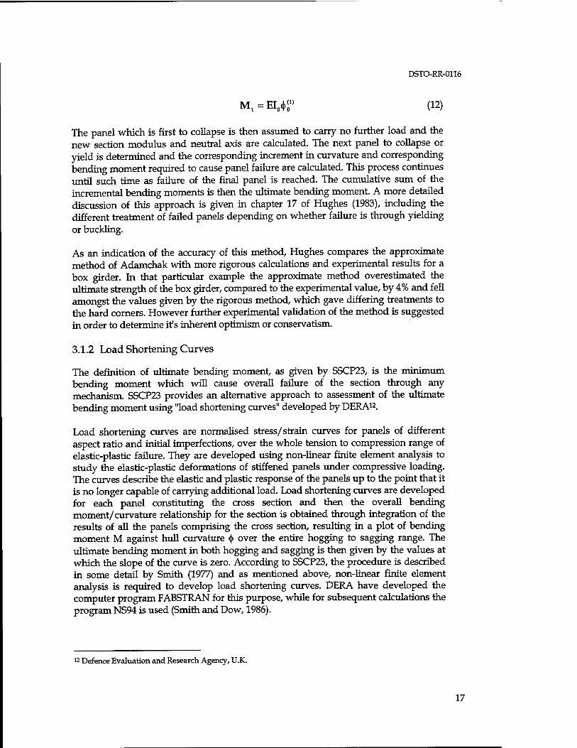
The ultimate collapse load calculated in this manner enables the progressive collapse of the hull to be determined, allowing for load shedding and changes in sectional properties, until such time that hull curvature reaches unacceptable limits and can no longer absorb any additional load. According to SSCP23, provided the design bending moment Md, given for example by equation (6), is calculated with an appropriate probability of exceedance in the ship's life, and the displacement and mass distribution have been selected to ensure the worst loading case, then for ultimate strength assessment it is sufficient to ensure that Mu is greater than Md without any further margin. However, if the fall off of load carrying capacity is rapid, as shown by the bottom curve in Figure 9, a value of at least Mu/Md > 1.1 is recommended.
<*/<*„
1.0
0.8 _
0.6 .
A - Elastic-perfectly plastic
B - Well designed
C - Poorly designed
3.0
Figure 9. Indicative Load Shortening Curves for Stiffened Panel.
3.1.3 Panel Collapse as a Criteria for Hull Failure
The process of ultimate strength assessment as outlined above is a complex task and at the design stage is an iterative procedure. In practice, for example at the concept design stage or if suitable computer programs are not available, an alternative more approximate approach may be necessary. For many practical purposes it can be accepted that collapse of any stiffened panel will constitute hull failure, and so the acceptable ultimate bending moment, Mf (Moment to /ailure), can be defined as the minimum bending moment required to initiate failure of any stiffened panel. For cross stiffened warships, failure may be may considered as (i) interframe (i.e. between transverse frames) collapse of plate and stiffeners, or, (ii) as gross panel collapse involving both longitudinal and transverse stiffeners. Whereas for a transversely stiffened ship, simple plate failure is equivalent to interframe collapse and will constitute hull failure. It should be normal practice in the design of a ship to ensure
18
DSTO-RR-0116
that failure tinder ever increasing load will occur in a hierarchical manner, with the least critical failures occurring first. The order being:
. plate buckling
. frame tripping • interframe collapse between transverse frames . gross panel collapse involving both longitudinal and transverse stiffeners
Hughes (1983) provides analytical methods for determining minimum properties of plates and stiffeners, and of determining failure stress in terms of longitudinal stress, to ensure that panel scantlings are adequate. Even a scarcely adequate summary of these methods is outside the scope of this document, so the reader is therefore referred to Hughes (1983) and in particular chapter 14 deals with ultimate strength of stiffened panels.
4. Application of Loads using Finite Element Analysis
If finite element analysis is to be used for structural strength assessment then a suitable method must be used to apply loads to the FEA model. To some extent this is dependent upon the method used to define and calculate the loads in the first place and also the particular finite element analysis software being used. For this reason the discussion will refer to the MAESTRO and ANSYS finite element analysis programs13
which are the currently used by DSTO.
4.1 General Approach to Ship Structural Modelling
Finite element analysis of ships can fall into three categories
• Global or whole ship model where the ship is modelled using a coarse mesh • Local model where a refined mesh of a particular part of the ship's structure, such
as a half-width section of the hull and/or superstructure, is modelled using a detailed mesh and boundary conditions supplied by the global analysis
• Stress concentration analysis where a very detailed analysis of a minor structure such as a hatchway, is carried out to determine the geometrical stress concentration factor for fatigue analysis calculations.
It is the approach to the first of these items which is of greatest concern in this paper, as it has a significant effect on the results of analysis of the other types. The final category is not so greatly influenced by the other analyses if the aim is simply to determine stress concentration factors. In that case, unit loads are applied to determine the stress concentration factors, however if a fatigue life analysis is to be conducted, then accurate estimation of the field stress in the vicinity of the component is essential.
13 ANSYS is a general purpose finite element program.
19

DSTO-RR-0116
Typically a coarse mesh model is used for whole ship analysis in order to generate boundary conditions, generally displacements, to be applied to refined mesh models of areas of interest such as high stress locations and stress concentrations. Virtually all FEA programs now automate this process through the use of the 'super element technique' whereby the refined mesh is considered as a 'super element' by the global analysis and the boundary displacements are transferred automatically to the local model.
The level of detailed that can be modelled in a global analysis is dependant upon software limitations, hardware platform and available resources to develop the model and perform the analysis, and so a compromise between model complexity and quality of results is usually required. A coarse mesh model will consist primarily of orthotropic 2D-plane elements whose properties are defined to represent the average properties of the stiffened panels making up the vessel, particularly those which are longitudinally effective. This enables the number of elements required for the models to be reduced but retains the overall hull girder properties. Major bulkheads, main longitudinal hull girder(s) and transverse frames will be normally be modelled in a similar manner or using beam elements if local bending stiffness is significant.
4.2 Static and Static-Balance Load Cases
The simplest loading case for whole-ship analysis is that of still water bending which should always be the first loading case considered so that the correct weight distribution is obtained for subsequent analysis. The ship is at rest in a state of equilibrium between the weight of the ship and her cargo/payload and the resultant buoyancy forces. The buoyancy is readily calculated with a high level of accuracy from knowledge of the three dimensional shape of the hull and appendages and of the forward, after and midships drafts of the ship. The mass distribution is obtained from design information regarding lightships weight and weight measurements of fluids, cargo and other consumables and equipment aboard the ship.
To apply these loads to a whole ship finite element model a number of approaches can be used, but the most direct is the application of hydrostatic pressure to the wetted surface of elements. The buoyancy pressure distribution varies linearly with water depth and pressure loads are applied as point load vectors at the nodes and the transformation from pressure to point load is usually carried out by the finite element program, e.g. the MAESTRO IMMERSION keyword. Most finite element programs allow the pressure to be defined as linear function of distance so that design pressure loads, such as for slarnming, may be calculated directly by the program, e.g. the ANSYS SFGRAD command. The weight of the ship is modelled as a combination of distributed self-weight loads for hull, systems and minor equipments, pressure loads for fluids and cargo, and point or line loads for large equipments. Whenever possible, line loads should be applied at areas with natural restraints such as along a girder, transverse frame or a hard chine, rather than across unsupported plate elements. It is necessary to specify fixed boundary conditions, to at least one node and typically to the translational modes at the extreme end nodes of the model in the trimmed
20
DSTO-RR-0116
condition, so as to avoid singularity of the stiffness matrix. It will usually be necessary to apply an iterative procedure to balance the weight and buoyancy forces at the correct trim by adjusting the weight and buoyancy distributions as necessary, so as to minimise the reaction forces at the fixed nodes, ideally to zero.
The static-balance load case is simply an extension of the still water case. Using the weight distribution from the still water case, the aim is to balance the ship on an assumed wave profile by iteratively adjusting the draught and trim until the net force and moment on the ship is (ideally) zero. It has been common practice in simple beam calculations of hull girder strength to use a trochoidal wave profile, as this profile more accurately represents the shape of real unidirectional waves than does a sinusoidal wave. If possible this should be continued, however it should be noted that the MAESTRO program WAVE and WAVEONLY keywords only provide the capability to generate sinusoidal wave profiles. At present, MAESTRO does not balance the ship on the wave, this is an iterative process which is left to the user14. When heeling or trimming the vessel in a MAESTRO analysis, it should be noted that the program inclines the water surface about the global Z axis (athwartships direction) rather than changing the inclination of the structure so the angles will be of opposite sign. As the pivot point is about global Z axis, if the origin is not centre of flotation each change in trim will result in a corresponding change in buoyancy force which makes the iteration procedure more difficult.
In the static-balance case, when the correct draft and trim of the vessel have been achieved and the ship is balanced, it is possible that there will be a significant longitudinal resultant forces at the fixed forward and after nodes, due to the tendency of the ship to "slide off" the static wave fixed at midships. The effect of this reaction should be considered in context of the overall analysis to assess whether or not an attempt should be made to shift the location of the peak or trough of the wave so as to minimise the three X-Z plane reactions.
A feature of many general purpose finite element programs such as ANSYS is a facility to perform inertial relief calculations under a static analysis. This is a procedure that calculates the accelerations which counter-balance the net applied loads so that the analysis becomes equivalent to a free-body or unrestrained analysis. This effectively removes the need for the ship to be iteratively balanced on the wave and therefore obscures the effect of this balancing process. It is recommended that this approach be treated with some caution so that limits be placed on the magnitude of the inertial relief calculations to ensure that the resultant load case is not substantially different from the same nominal iteratively-balanced load case. A suitable approach would be to roughly balance the model so that end node reaction forces are within a few percent of the total displacement and then to invoke the inertial relief facility to complete the balance.
14 Proteus Engineering, the MAESTRO software distributors, have recently been contracted by DSTO to provide a load balance routine in MAESTRO to automate the process of calculating the static position of a hull within a specified wave in terms of draft, trim and roll.
21

DSTO-RR-0116
4.3 Wave Spectrum Load Case
Ideally, to study a ship's response to a particular wave environment, it is desirable to be able to apply a wave spectrum as the load input to a finite element model. This is in fact an extremely complex task and there is little evidence in the literature of this being done on a routine basis.
4.3.1 Analysis of the RAN LST/THSS
One available example of where a wave spectrum load input has been applied to a finite element model is the investigation of Royal Australian Navy's Landing Ship, Tank (LST)/ Training Helicopter Support Ship (THSS) conducted by Vipac (1995). The loading information for the LST/THSS analysis was provided as a combination of the input wave spectrum15 and the frequency response functions for heave and pitch accelerations and vertical shear force components; wave exciting forces, hydrodynamic forces due to relative body motion and static restoring forces. The frequency response functions were provided only for the vertical plane and the head seas case. The analysis was done in such a way that the stress RAOs for every element node was determined and then the stress response spectrum for each node was determined using the linear relationship:
Sw(coe) = RAO.Sc(©e). (13)
The extreme stress amplitude response, excluding still water bending and slamming effects, was determined for the input sea state using equation (10) and then added to the still water bending response.
The spectral wave load procedure used for the LST/THSS was as follows:
• The nodal mass distribution was determined by applying the still water buoyancy force and a 1 g (9.81 m/s) downwards acceleration to the model.
• The stresses for the still water load case were determined. • Frequency response functions for wave exciting forces, hydrodynamic forces due
to relative body motion between vessel and water (denoted as dynamic forces) and the static restoring forces were determined at each of 21 hull stations using strip theory.
• At frequency intervals of 0.01 hertz , the shear force and phase at each station corresponding to a 1 metre amplitude sine wave was determined (i.e. equal to the amplitude ratio times cosine of the phase angle, multiplied by 1 metre) and distributed as a pressure force to the individual finite element nodes using a spreadsheet program. The pressure was assumed to vary linearly from zero at the free surface to a maximum at the keel, such that when integrated over the section surface it was equal to the applied shear force.
15 In this case the Bretschneider spectrum was used.
22
DSTO-RR-0116
• The pressures were applied to the ANSYS finite element model as a series of load cases at frequencies from 0.01 Hz to 2.0 Hz, and balance for each load case was achieved using the inertial relief method. The resulting stresses provide the stress per unit wave amplitude and so give the nodal stress RAOs for the vessel.
• The stress spectra at each node were then calculated for the input wave spectrum using equation (13) and the extreme responses calculated using equation (10), with a = 0.01. These stresses were then added to the stresses for the still water analysis to provide the extreme responses for the given sea state with a probability of one percent.
While the procedure used in the LST/THSS analysis appears to be valid, it is suggested that the accuracy of the answers must be treated with caution until a more thorough assessment of the method and results can be conducted. The main concern is that objective assessment of the results is difficult due to the complexity of the analysis and the general lack of physical appreciation of nodal stress RAOs. A more thorough evaluation of the method is therefore recommended.
From the literature, there appears to be no clear or accepted procedure for the application of wave spectrum loading directly to finite element models in order to determine structural stresses. This is an area where future work is needed to establish an appropriate procedure and to validate results against alternative methods and full scale measurement. It is not possible to conduct such analyses for the current report and it is strongly recommended that this be done in the future.
5. Conclusions and Recommendations
A review of loads calculation methods for surface ships and their application to finite element models has been conducted. Different formulae for the design static wave height have been presented together with background information as to their application. The SSCP 8m wave criteria is considered appropriate for typical frigate
type warships while the 0.6-v/L wave is suggested for vessels over 200m as it allows for the increase in effective wave height with ship length while acknowledging the non-linear manner of this increase. Whichever approach is used, it is to be remembered that the wave height formulae give the most probable maximum lifetime wave bending moment and that still water loads, differences between hogging and sagging, and slamming loads need to be included in the overall analysis.
As an alternative to the static-balance wave, strip theory may be used to predict wave loads on ships in different sea states and for different ship speeds and headings. A probabilistic assessment then enables the probable maximum load for the given sea state to be predicted and if all combinations of ship speed, heading and sea state are considered, long term design extreme and fatigue loads can be evaluated.
The accuracy of the strip theory and other codes has been investigated by several researchers and it appears that the error associated with predicting midships bending
23
DSTO-RR-0116
moment using strip theory is of the order of 10% to 20%. This accuracy is reduced further towards the ends of the vessel and as seas become progressively more beam-on. Calculations using the 3-D panel method code PRECAL, show little or no improvement over strip theory codes but are considerably more complex. At this stage the extra computational effort appears to be unwarranted although future code and hardware developments are likely to improve this position.
Methods for determining the ultimate bending moment that may be carried by a structure are discussed. For RAN purposes, the most appropriate method at present appears to be that of Adamchak which is incorporated into the MAESTRO program. There is however limited, albeit very encouraging, correlation between numerical predictions and test data and further evaluation is therefore recommended. The use of load shortening curves as a means for determining ultimate strength is briefly discussed, but suitable computer programs are required for effective use of this method. For quick, 'back of the envelope1 calculations, analytical methods provided by Hughes (1983) enable the minimum load to collapse stiffened panels to be determined.
The application of loads to finite element models is relatively simple for still water and static-balance load cases, although a manual iterative procedure is necessary to balance the model upon the static-wave when conducting a MAESTRO analysis. The development of computer software to perform this task would be of considerable benefit. A method of application of a design wave load spectrum to a finite element model, as used in the analysis of the LST/THSS, is discussed and a more thorough evaluation of this method is recommended. It is recommended that further work also be done to establish an appropriate procedure for the direct application of wave spectrum loads onto finite element models and to validate results obtained against alternative methods and full scale measurements.
24

DSTO-RR-0116
6. Notation
a acceleration vector b(x) continuous longitudinal buoyancy distribution b(xi) discrete, sectionwise longitudinal buoyancy distribution E elastic (Young's) modulus p force vector g acceleration due to gravity H wave height, crest to trough | H (co e) | frequency response function
k total number of wave encounters for the particular sea state
L ship length, taken as length between perpendiculars unless specified LBP length between perpendiculars L static-balance wave load factor
m, m(x) mass, longitudinal mass distribution M bending moment Mas design sagging bending moment (excluding SWBM) Mdh design hogging bending moment (excluding SWBM) Mh hogging bending moment (including SWBM) M • bending moment at which the i-th panel fails mn n'th moment of the spectrum Ms sagging bending moment (including SWBM) MSw still water bending moment (+ve for hogging, -ve for sagging) Mu ultimate bending moment Mwh wave induced sagging bending moment (excludes SWBM) Mws wave induced hogging bending moment (excludes SWBM) Np number of panels (for ultimate strength calculation) 9t(© ) Fourier transform of the time dependant response function SWBM still water bending moment S gj (o e) encounter response spectrum
Sc (co e) encounter wave spectrum
t time T duration of a specified sea state, in hours T average zero-upcrossing period in seconds
v velocity vector w(x) continuous longitudinal weight distribution w(xi) discrete, sectionwise longitudinal weight distribution y. distance from the neutral axis after removal of failed panels
a risk parameter, (k=0.01 means a 1% risk of exceeding the design value) A displacement 5 differential e average applied strain at time of panel collapse
25

DSTO-RR-0116
s average applied strain at onset of panel yield
s , s average strain act which a panel collapses, yields
^ curvature i (i) curvature at which a panel collapses or yields
X wave length ? average amplitude
7 design extreme amplitude for a particular sea state
7 probable extreme amplitude for a particular sea state
£7^ ) Fourier transform of the time dependant wave function
© encounter frequency
26

DSTO-RR-0116
7. References
Adamchak J.C. "ULTSTR: A Program For Estimating The Collapse Moment Of A Ship's Hull Under Longitudinal Bending", DTNSRC Report 82/076, October 1982.
Aksu. S., Price W.G. and Temarel P. "Load and Stress Distributions on Bulk Carriers and Tankers in Various Load Conditions", International Conference on Tankers and Bulk Carriers - The Way Ahead", R.I.NA. 10-11 December 1992.
Ando S. "Experimental Validation of PRECAL, Part 1: Responses to Regular Head Waves", DREA Technical Memorandum 95/212, May 1995.
Belik O., Bishop R.E.D. and Price W.G. "A Simulation of Ship Responses due to Slamming in Irregular Head Waves", Trans R.I.N.A. Vol 125,1983.
Bishop R.E.D. and Price W.G. "Hydroelasticity of Ships", Cambridge University Press, 1979.
Clarke J.D. "Wave Loading of Warships", Journal of Naval Science, Vol 12, No.41986.
Chalmers D.W. "Hull Structural Design using Stiffness as a Criteria", Trans RINA, Vol. 130,1988
Dalzell J.F. "Experiment - theory correlation: linear ship motion and loading theory", Eighteenth General Meeting of American Towing Tank Conference, Annapolis, Maryland, 23-25 August 1977.
Dalzell J.F., Thomas III W.L. and Lee W.T. "Correlations of Model Data with Analytical Load Predictions for Three High Speeds Ships", DSWC Carderock Report No SHD- 1374-02, Sept 1992. (Limited Release)
Doctors L.J. "Hydros: Integrated Software for the Analysis of Hydrostatics and Hydrodynamics of Marine Vehicles", Tenth International Maritime and Shipping Symposium (Shipshape 2000), University of NSW, 8-9 November 1993.
Evans J.H.(ed) "Ship Structural Design Concepts", Cornell Maritime Press, Cambridge, MD, 1975.
Graham R. and Millar G. "SHIPM02: An Updated User's Manual for the SHIPMO Program Incorporating Measured Sea Spectra and Wave Loads", DREA Tech Memo 84/G, May 1984
Hughes O.F. "Ship Structural Design. A Rationally-Based, Computer-Aided, Optimisation Approach", John Wiley and Sons, New York, 1983.
27

DSTO-RR-0116
Jasper N. H. "Statistical Distribution Patterns of Ocean Waves and of Wave Induced Ship Stresses and Motions with Engineering Applications." Trans. SNAME, (1956) Vol. 64, pp. 375 -432.
Jacobs W.R. "The Analytical Calculations of Ship Bending Moments in Regular Waves", Journal of Ship Research. 2(1), 1958
Kamel H. A. and Liu D. "Application of the Finite Element Method to Ship Structures". Computers and Structures, Vol. 1 pp. 103 -130.1971.
Korvin-Kroukovsky Prof. B. V. "Investigation of Ship Motions in Regular Waves", Trans SNAME, 1955.
Korvin-Kroukovsky Prof. B. V. and Jacobs W.R. "Pitching and Heaving Motions of a Ship in Regular Waves", Trans SNAME, 1957.
Lewis E.V. "A Study of Midship Bending Moment in Irregular Head Seas", Journal of Ship Research. 1(1), 1957
Lloyds Register. "ShipRight Design, Construction and Lifetime Care Procedures. Structural Design Assessment Procedure, Direct Calculations - Guidance Notes (Tankers)", Version 1.0, Oct 1994.
Graham R. and Millar G. "SHIPM02: An Updated User's Manual for the SHIPMO Program Incorporating Measured Sea Spectra and Wave Loads", DREA Tech Memo 84/G, May 1984
MAESTRO Data Preparation Manual (MAESTRO Vers 7.0) February 1995, Optimum Structural Design, Inc.
McTaggart K.A. & Ando, S. "A Review of Eight Seakeeping and Hydrodynamic Load Prediction Codes", DREA Tech Memo 92/315, Sept 1993.
McTaggart K.A. "SHIPM06: An Updated Strip Theory Ship Motion Program", DREA Tech Memo 93/213, Oct 1993.
McVee J. D. "A Finite Element Study of Hull-Deckhouse Interaction", Computers and Structures Vol 12, pp. 371 - 393 Oct. 1980.
NAVSEA, "Structural Design Manual for Naval Surface Ships", NAVSEA 0900-LP-097- 4010,15 Dec 1976.
Ochi M. K. "Wave Statistics for the Design of Ships and Ocean Structures", SNAME Trans. Vol. 86,1978, pp. 47 - 76.
Ochi M. K. and Motter L. E. "Prediction of Slamming Characteristics and Hull Responses for Ship Design", SNAME Trans. Vol. 811973 pp. 144 -176.
28

DSTO-RR-0116
Phelps B.P. "Ship Structural Response Analysis: Spectra and Statistics", DSTO Report DSTO-TR-0183, Aug 1995.
Phelps B.P. "Ultimate Strength and Fatigue Life Assessment of Surface Ships", Regional Maritime Conference - Indonesia, Nov 7-8,1995.
Phelps B.P. and Boyd J.C.M. "HMAS SWAN May 1994 Hydrodynamic Load Trial, Analysis of Results", DSTO Report DSTO-RR- ,1997
Salvesen N., Tuck E. O. and Faltinsen O. "Ship Motions and Sea Loads" Trans. SNAME Vol. 78 (1970)pp. 250 - 287.
Sikora J.P., Dinsenbacher A. and Beach J.E. "A Method for Estimating Lifetime Loads and Fatigue Lives for SWATH and Conventional Monohull Ships", Naval Engineers Journal, May 1983.
St. Denis M. and Pierson W.J. "On the Motions of Ships in Confused Sea", Transactions of SNAME, 1953.
Smith C.S. "Influence of Local Compression Failure on Ultimate Longitudinal Strength of A Ship's Hull", Proceedings of International Conference on Practical Design in Shipbuilding (PRADS), Tokyo, Oct, 1977.
Smith C.S. and Dow R.S. "NS94: Ultimate Strength of a Ships Hull under Biaxial Bending", Report ARE TM(UMS) 87204, Admiralty Research Establishment, Dunfermline, Dec 1986.
SSCP23. "Design of Surface Ship Structures", Sea Systems Controllerate Publication No. 23, Ministry of Defence, Foxhill, Bath, 1989.
Thomson R. "RAN Ship Structural Design Assessment", DNA Tech Memo A014629, Paper Presented to ABC-36 Hydrodynamic Loading Working Group, May 1989.
Vipac Engineers and Scientists Ltd, "LST and THSS Description of Analyses and Results", Report VIPAC-SYS-4828-00 Prepared for Directorate of Naval Architecture, 27 June 1996.
29

DISTRIBUTION LIST
Determination of Wave Loads for Ship Structural Analysis
B.P. Phelps
AUSTRALIA
DEFENCE ORGANISATION
Task Sponsor DNPSE, CP1-5-14, Attention Mr R. Thomson (2 copies)
S&T Program Chief Defence Scientist 1 FAS Science Policy t shared copy AS Science Corporate Management -* Director General Science Policy Development Counsellor Defence Science, London (Doc Data Sheet) Counsellor Defence Science, Washington (Doc Data Sheet) Scientific Adviser to MRDC Thailand (Doc Data Sheet) Director General Scientific Advisers and Trials/Scientific Adviser Policy and
Command (shared copy) Navy Scientific Adviser Scientific Adviser - Army (Doc Data Sheet and distribution list only) Air Force Scientific Adviser Director Trials
Aeronautical and Maritime Research Laboratory Director Chief of Maritime Platforms Division J. Ritter B. Phelps (5 copies)
DSTO Library Library Fishermens Bend Library Maribyrnong Library Salisbury (2 copies) Australian Archives Library, MOD, Pyrmont (Doc Data sheet only)
Capability Development Division Director General Maritime Development Director General Land Development (Doc Data Sheet only) Director General C3I Development (Doc Data Sheet only)
Navy SO (Science), Director of Naval Warfare, Maritime Headquarters Annex,
Garden Island, NSW 2000 (Doc Data Sheet and distribution list only) ANZAC Ship Project Director

Army ABCA Office, G-l-34, Russell Offices, Canberra (4 copies) SO (Science), DJFHQ(L), MILPO Enoggera, Queensland 4051 (Doc Data Sheet
only) NAPOC QWG Engineer NBCD c/- DENGRS-A, HQ Engineer Centre Liverpool
Military Area, NSW 2174 (Doc Data Sheet only
Intelligence Program DGSTA Defence Intelligence Organisation
Corporate Support Program (libraries) OIC TRS, Defence Regional Library, Canberra Officer in Charge, Document Exchange Centre (DEC), 1 copy *US Defence Technical Information Center, 2 copies *UK Defence Research Information Centre, 2 copies *Canada Defence Scientific Information Service, 1 copy *NZ Defence Information Centre, 1 copy National Library of Australia, 1 copy
UNIVERSITIES AND COLLEGES
Australian Defence Force Academy Library Head of Aerospace and Mechanical Engineering
Deakin University, Serials Section (M list), Deakin University Library, Geelong, 3127 Senior Librarian, Hargrave Library, Monash University Librarian, Flinders University
OTHER ORGANISATIONS
NASA (Canberra) AGPS
OUTSIDE AUSTRALIA
ABSTRACTING AND INFORMATION ORGANISATIONS INSPEC: Acquisitions Section Institution of Electrical Engineers Library, Chemical Abstracts Reference Service Engineering Societies Library, US Materials Information, Cambridge Scientific Abstracts, US Documents Librarian, The Center for Research Libraries, US
INFORMATION EXCHANGE AGREEMENT PARTNERS Acquisitions Unit, Science Reference and Information Service, UK Library - Exchange Desk, National Institute of Standards and Technology, US
SPARES (10 copies)
Total number of copies: 61
31

Page classification: UNCLASSIFIED
DEFENCE SCIENCE AND TECHNOLOGY ORGANISATION DOCUMENT CONTROL DATA
2. TITLE
Determination of Wave Loads for Ship Structural Analysis
4. AUTHOR(S)
B.P. Phelps
6a. DSTO NUMBER DSTO-RR-0116
8. FILE NUMBER 510/207/0769
6b. AR NUMBER AR-010-375
9. TASK NUMBER NAV 94/095
1. PRIVACY MARKING/CAVEAT (OF DOCUMENT)
3. SECURITY CLASSIFICATION (FOR UNCLASSIFIED REPORTS THAT ARE LIMITED RELEASE USE (L) NEXT TO DOCUMENT CLASSIFICATION)
Document Title Abstract
(U) (U) (U)
5. CORPORATE AUTHOR
Aeronautical and Maritime Research Laboratory PO Box 4331 Melbourne Vic 3001 Australia .
6c. TYPE OF REPORT Research Report
10. TASK SPONSOR DNPSE
13. DOWNGRADING/ DELIMITING INSTRUCTIONS
None
7. DOCUMENT DATE November 1997
11. NO. OF PAGES 29
12 NO. OF REFERENCES 39
14. RELEASE AUTHORITY
Chief, Maritime Platforms Division
15. SECONDARY RELEASE STATEMENT OF THIS DOCUMENT
Approved for -public release
OVERSEAS ENQUIRIES OUTSIDE STATED LIMITATIONS SHOULD BE REFERRED THROUGH DOCUMENT EXCHANGE CENTRE, DIS NETWORK OFFICE, DEPT OF DEFENCE, CAMPBELL PARK OFFICES, CANBERRA ACT 2600 16. DELIBERATE ANNOUNCEMENT
No Limitations
17. CASUAL ANNOUNCEMENT Yes 18. DEFTEST DESCRIPTORS
loads (forces); hulls (structures); RAN ships; structural analysis; bending; hydrodynamics; sea states
19. ABSTRACT
The adequacy of a structure can only be realistically determined if it is assessed with sound knowledge of the loads that are likely to be applied to that structure. Therefore, methods for evaluating hydrodynamic loads on ships have been reviewed in order to assess their applicability to RAN ships. The different methods are used at various stages of design or analysis dependant upon the amount of time and information available to the designer/analysist. Methods for calculating still water loads and wave bending loads using the Static-Balance method are outlined and comparisions of the methods provided. The use of Strip Theory methods to determine the probable and design extreme amplitude shear force or bending for a particular sea state is explained and predictions are compared with full scale measurements. Methods for long term load predictions such as Adamchak's Method and load shortening curves are also discussed. Methods for applications of these loads to finite element models are given and the particular case of an analysis of an RAN ship is discussed.
Page classification: UNCLASSIFIED

^
CO rn > TO n x 70 rn
o TO_
o CO —I o
I TO TO ■ o
> TO
I o O
1 CO \l
Z o < rn
CD rn TO
O O XI
DSTO* AUSTRALIA
AERONAUTICAL AND MARITIME RESEARCH LABORATORY GPO BOX 4331 MELBOURNE VICTORIA 3001
AUSTRALIA, TELEPHONE (03) 9626 7000