determination of the conservatism degree in …m2d/proceedings_m2d2017/data/papers/6781.pdfthe...
TRANSCRIPT
Proceedings of the 7th International Conference on Mechanics and Materials in Design Albufeira/Portugal 11-15 June 2017. Editors J.F. Silva Gomes and S.A. Meguid. Publ. INEGI/FEUP (2017)
-1127-
PAPER REF: 6781
DETERMINATION OF THE CONSERVATISM DEGREE IN THE
LEVEL-1 OF THE STANDARD API-579-1/ASME-FFS-1-2007 FOR THE
ASSESSMENT OF DENTS IN INTERNAL PRESSURE PIPE-LINE David Casarrubias, Jorge González, Diego Rivas
(*), Manuel Beltrán
Esc. Sup. de Ingeniería Química e Industrias Extractivas, Instituto Politecnico Nacional, Mexico City, Mexico (*)Email: [email protected]
ABSTRACT
In this work, the conservatism degree in the assessment of dents of the standard API-579/ ASME FFS-1 part 12, was determined through finite element method (FEM) simulations. The study was applied for pipeline steel subjected to internal pressure. In the modelling by FEM, three main conditions were considered as variables: increase of length and width of the dent, gradual increase of depth dent and progressive variation of the internal pressure. The obtained results indicate that there is a 46% degree of conservatism in the level 1 assessment of dents. This means that, a pipeline could reach a depth dent over the 13%, respect to the outside diameter of the pipe, without requiring an immediate repair or replacement of the component. Additionally according with the results, the depth dent is not the only determining factor to assessment the damage severity, since both the length and width of the dent as well as the pipeline internal pressure are important factors to considerer for the assessment.
Keywords: Integrity assessment, depth dent, pipeline steel.
INTRODUCTION
The dent damage as a cause of failure, in the transport pipelines of hydrocarbons that are exposed to the environment, is also the most difficult to evaluate because of their geometric complexity [1-7]. A simple dent is defined as a damage that causes a change in the permanent curvature of the wall of the pipe without reducing the thickness, it is usually assumed that it does not contain other defects or imperfections [8]. The simple dents represent mechanical damages, which can fail to loads by internal pressure smaller than those of design, because they generate a concentration of stress and a high deformation in the contours as well as in the dent [9].
The origin of the dents is mainly due to the damage done by third parties and the ground displacements in which there are strong blunt objects having direct contact with the pipeline, generating elastoplastic deformation on its surface [10, 11].
Assessment of dents, using the standard API 579-1 / ASME FFS-1, emerges as a tool for fitness for service of a damaged element [12]. In Level 1assessment, in order to establish an acceptance or rejection criteria of damage, establishes a dent depth limit of 7%, without deepen on the integrity of the pipeline. Actually, a reduction of internal pressure is proposed to continue the operation [7, 9].

Topic-L: Industrial Engineering and Management
-1128-
The Level 2 assessment indicates that if the component is not subjected to work cycles it can continue operating. By contrast, if it is submitted to work cycles, it will be necessary to calculate the number of acceptable cycles that can continue operating the pipeline.
The level 3 assessment is realized by the use of the Finite Element Method (FEM), which is the most accurate and used method for stress analysis [5-7, 11, 13-16]. The analytical method contained within Annex B1 of API 579-1 / ASME FFS-1: 2007 may be used for stress analysis when performing a fitness assessment of a component with a flaw. These methods are typically employed in a Level 2 or Level 3 assessment. The detailed assessment procedure uses the results of a stress analysis provided, to evaluate components by plastic collapse, local failure, loop and cyclic loads.
The present work analyzes the conservatism degree of the international standard API 579-1 / ASME FFS-1, 2007, Part 12 named "Assessment of Dents, Gouges and Dent-Gouge Combination" at its evaluation level 1; modeling by FEM. The analysis was performed under three different conditions: the progressive increase of the length and width (aspect) of the dent, progressive increment in the dent depth and finally, the progressive variation of the load by internal pressure.
MATERIAL AND METHODS
Physical model
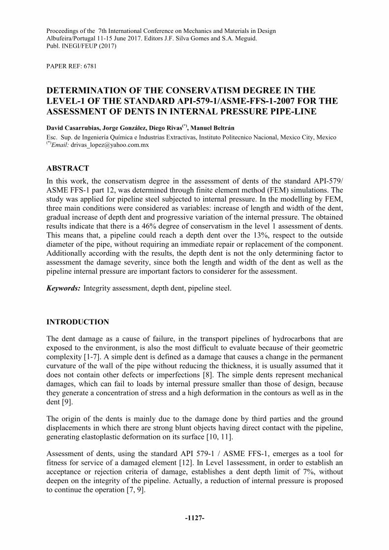
A physical model was performed as shown in Figure 1 which has a dent depth of 10%, measured with respect to the outer diameter.
Fig. 1 - Dented pipeline.
Flawless model
A pipe with the original dimensions of the physical model (omitting the dent) was realized by a 3D CAD software, in order to know the stress state generated in this component. First, an analytical calculation of the state of stresses present in the tube was made by the Barlow equations, which correspond to the circumferential stress (σC), according to equation 1:
�� � ���� (1)
And the longitudinal stress (σL), by equation 2:
�� � ��� (2)
15 cm
1.27 cm
2.54 cm
7.62 cm
Proceedings of the 7th International Conference on Mechanics and Materials in Design
-1129-
Where: P= Internal pressure D= Outer cylinder diameter t= Wall Thickness
The simulation of the flawless pipeline was done to know the generated stress in an isotropic, continuous and homogeneous material, according to the mechanics of the continuous medium. In addition, the Von Mises yield criteria was used to compare the FEM and the analytical results, in order to know the percentage of error that is made when performing simulations.
Besides, from the Barlow circumferential stress equation, the failure pressure (Pf) of the component under operation conditions was calculated, to determine the integrity reduction produced as a consequence of the presence of a dent.
First condition of experimentation: variation on length and width of the dent.
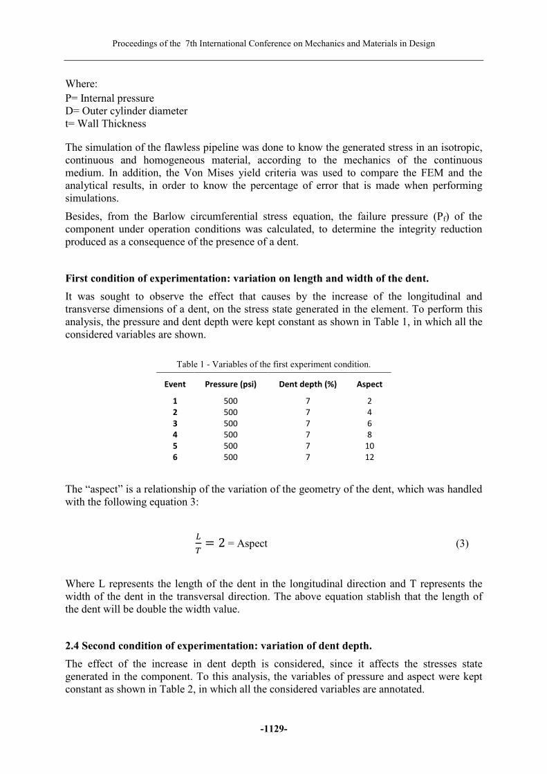
It was sought to observe the effect that causes by the increase of the longitudinal and transverse dimensions of a dent, on the stress state generated in the element. To perform this analysis, the pressure and dent depth were kept constant as shown in Table 1, in which all the considered variables are shown.
Table 1 - Variables of the first experiment condition.
Event Pressure (psi) Dent depth (%) Aspect
1 500 7 2
2 500 7 4
3 500 7 6
4 500 7 8
5 500 7 10
6 500 7 12
The “aspect” is a relationship of the variation of the geometry of the dent, which was handled with the following equation 3:
� � 2 = Aspect (3)
Where L represents the length of the dent in the longitudinal direction and T represents the width of the dent in the transversal direction. The above equation stablish that the length of the dent will be double the width value.
2.4 Second condition of experimentation: variation of dent depth.
The effect of the increase in dent depth is considered, since it affects the stresses state generated in the component. To this analysis, the variables of pressure and aspect were kept constant as shown in Table 2, in which all the considered variables are annotated.

Topic-L: Industrial Engineering and Management
-1130-
Table 2 - Variables of the second experiment condition.
Event Pressure (psi) Dent depth (%) Aspect
1 600 4 4
2 600 7 4
3 600 10 4
4 600 13 4
5 600 16 4
6 600 19 4
The dent depth (dp) is considered with respect to the outside diameter of the pipe (D) handled with equation 4, the maximum height of the dent is in the central zone and its depth varies as it approaches the edges axial and lateral.
� � �(100%) � A% = Dr (4)
Third condition of experimentation: variation in the internal pressure.
It was sought to observe the effect of the internal pressure on the dent and how it affects the stress state generated in the component. In order to perform this analysis, the variables of dent depth and aspect were kept constant as shown in Table 3.
Table 3 - Variables of the third experimental condition.
Event Pressure (psi) Dent depth (%) Aspect
1 100 10 4
2 200 10 4
3 300 10 4
4 400 10 4
5 500 10 4
6 600 10 4
7 700 10 4
FEM simulations
In order to obtain a more precise analysis of the stresses generated in the dent, the standard API 579-1 suggests to use a refinement in the analysis zone. In this work, a mesh of 0.1 inches in the whole element is used. In addition, the tetrahedral method mesh was used, which generates 4 nodes and 151,572 nodes, distributed throughout the element. Once the mesh was obtained, the boundary conditions were programed. According to the classification of loads of the API 579-1, only the load by internal pressure was considered. On the other hand, the fixed conditions of the component were set as the ends of the pipe, as shown in Figure 2.

Proceedings of the 7th International Conference on Mechanics and Materials in Design
-1131-
Fig. 2 - Fixed component supports.
The mechanical properties assigned to the FEM model are shown in Table 4. The material was assessed under non-linearity conditions as set out in API 579-1 in Annex B1. In addition, the tensile strength properties were obtained from previous work of Ángel Islas [9], who performed an experimental stress-strain curve of the material.
Table 4 - Mechanical properties for the FEM model.
Property Value
Young Modulus 29950.30 ksi
Ratio of Poisson 0.3
Density 490.0595 lb/ ft3
UTS 61.74 ksi
Yield Stress 43.30 ksi
K 128.46949
N 0.3625
RESULTS AND DISCUSSION
Flawless model
The FEM model of the flawless pipe show that a maximum Von-Mises stress of 14.053 psi, as shown in Figure 3.
Fig. 3 - Stresses generated in a pipeline without defects.
Topic-L: Industrial Engineering and Management
-1132-
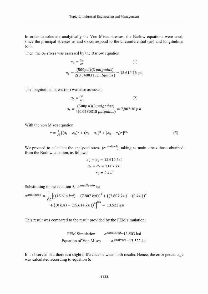
In order to calculate analytically the Von Mises stresses, the Barlow equations were used, since the principal stresses σ1 and σ2 correspond to the circumferential (σC) and longitudinal (σL).
Then, the σC stress was assessed by the Barlow equation
�� � ���� (1)
�� � (500���)(3��������)2(0.0480315��������) � 15,614.76psi
The longitudinal stress (σL) was also assessed:
�� � ��� (2)
�� � (500���)(3��������)4(0.0480315��������) � 7,807.38���
With the von Mises equation
� � (√� *(�( − ��)� + (�� − �-)� + (�- − �()�./.0 (5)
We proceed to calculate the analyzed stress (σ analyzed), taking as main stress those obtained from the Barlow equation, as follows:
�� � �( � 15.6141�� �� � �� � 7.8071��
�- � 01��
Substituting in the equation 5, �2324562�7 is:
�2324562�7 � 1√2 89(15.6141��) − (7.8071��):� + 9(7.8071��) − (01��):�
+ 9(01��) − (15.6141��):�;/.0 � 13.5221��
This result was compared to the result provided by the FEM simulation:
FEM Simulation �<5=>42�?�=13.503 ksi
Equation of Von Mises �2324@6?�=13.522 ksi
It is observed that there is a slight difference between both results. Hence, the error percentage was calculated according to equation 6:
Proceedings of the 7th International Conference on Mechanics and Materials in Design
-1133-
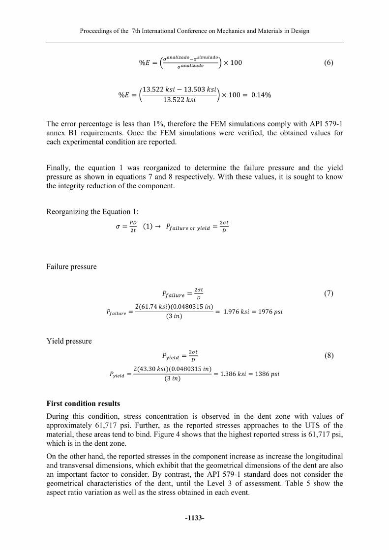
%A � BCDEDFGHDIJKCLGMNFDIJCDEDFGHDIJ O × 100 (6)
%A � Q13.5221�� − 13.5031��13.5221�� R × 100 � 0.14%
The error percentage is less than 1%, therefore the FEM simulations comply with API 579-1 annex B1 requirements. Once the FEM simulations were verified, the obtained values for each experimental condition are reported.
Finally, the equation 1 was reorganized to determine the failure pressure and the yield pressure as shown in equations 7 and 8 respectively. With these values, it is sought to know the integrity reduction of the component.
Reorganizing the Equation 1:
� � ���� (1) → TU254>V?7V@5?4� � �C�
�
Failure pressure
TU254>V? � �C�� (7)
TU254>V? � 2(61.741��)(0.0480315�W)(3�W) � 1.9761�� � 1976���
Yield pressure
T@5?4� � �C�� (8)
T@5?4� � 2(43.301��)(0.0480315�W)(3�W) � 1.3861�� � 1386���
First condition results
During this condition, stress concentration is observed in the dent zone with values of approximately 61,717 psi. Further, as the reported stresses approaches to the UTS of the material, these areas tend to bind. Figure 4 shows that the highest reported stress is 61,717 psi, which is in the dent zone.
On the other hand, the reported stresses in the component increase as increase the longitudinal and transversal dimensions, which exhibit that the geometrical dimensions of the dent are also an important factor to consider. By contrast, the API 579-1 standard does not consider the geometrical characteristics of the dent, until the Level 3 of assessment. Table 5 show the aspect ratio variation as well as the stress obtained in each event.

Topic-L: Industrial Engineering and Management
-1134-
Fig. 4 - Dented pipeline with aspect 12.
Table 5 - Variation in aspect of the dent.
Event Aspect σVM (ksi)
1 2 40.21
2 4 52.09
3 6 57.63
4 8 60.14
5 10 61.28
6 12 61.71
Second condition results.
Table 6 show the dent depth variation, as well as the stress obtained in FEM simulations.
Table 6 - Variation in dent depth.
Event Dent depth (%) σVM (ksi)
1 4 38.88
2 7 44.06
3 10 50.29
4 13 54.55
5 16 61.06
6 19 61.25
According to the FEM simulations, it is observed that a dent of 16% is already close to failing. For that reason, a 13% dent depth was proposed as a limit for the calculation of conservatism, to know what percentage of the component considers useful API 579-1.
Third condition results.
Table 7 show the internal pressure variation as well as the stress obtained in each event.
Proceedings of the 7th International Conference on Mechanics and Materials in Design
-1135-
Table 7 - Variation in the internal pressure of the pipeline.
Event Pressure (psi) σVM (ksi)
1 100 13.57
2 200 27.22
3 300 40.95
4 400 51.94
5 500 58.15
6 600 60.84
7 700 61.49
The increment of the internal pressure performed in the third condition, show that at pressure above the 700 psi, the simulated component tends to fail inevitably, due to the reduction of its integrity.
Critical areas
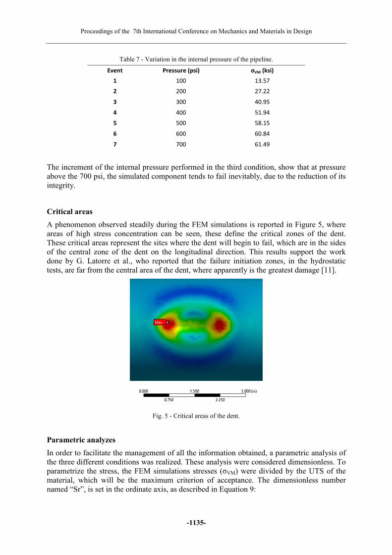
A phenomenon observed steadily during the FEM simulations is reported in Figure 5, where areas of high stress concentration can be seen, these define the critical zones of the dent. These critical areas represent the sites where the dent will begin to fail, which are in the sides of the central zone of the dent on the longitudinal direction. This results support the work done by G. Latorre et al., who reported that the failure initiation zones, in the hydrostatic tests, are far from the central area of the dent, where apparently is the greatest damage [11].
Fig. 5 - Critical areas of the dent.
Parametric analyzes
In order to facilitate the management of all the information obtained, a parametric analysis of the three different conditions was realized. These analysis were considered dimensionless. To parametrize the stress, the FEM simulations stresses (σVM) were divided by the UTS of the material, which will be the maximum criterion of acceptance. The dimensionless number named “Sr”, is set in the ordinate axis, as described in Equation 9:
Topic-L: Industrial Engineering and Management
-1136-
YV �CZ[\] (9)
First condition analysis
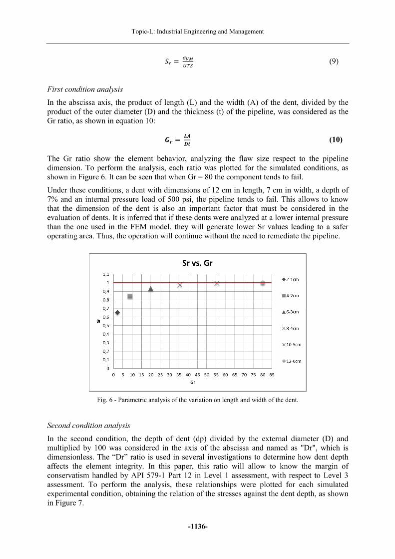
In the abscissa axis, the product of length (L) and the width (A) of the dent, divided by the product of the outer diameter (D) and the thickness (t) of the pipeline, was considered as the Gr ratio, as shown in equation 10:
^_ � `abc (10)
The Gr ratio show the element behavior, analyzing the flaw size respect to the pipeline dimension. To perform the analysis, each ratio was plotted for the simulated conditions, as shown in Figure 6. It can be seen that when Gr = 80 the component tends to fail.
Under these conditions, a dent with dimensions of 12 cm in length, 7 cm in width, a depth of 7% and an internal pressure load of 500 psi, the pipeline tends to fail. This allows to know that the dimension of the dent is also an important factor that must be considered in the evaluation of dents. It is inferred that if these dents were analyzed at a lower internal pressure than the one used in the FEM model, they will generate lower Sr values leading to a safer operating area. Thus, the operation will continue without the need to remediate the pipeline.
Fig. 6 - Parametric analysis of the variation on length and width of the dent.
Second condition analysis
In the second condition, the depth of dent (dp) divided by the external diameter (D) and multiplied by 100 was considered in the axis of the abscissa and named as "Dr", which is dimensionless. The “Dr” ratio is used in several investigations to determine how dent depth affects the element integrity. In this paper, this ratio will allow to know the margin of conservatism handled by API 579-1 Part 12 in Level 1 assessment, with respect to Level 3 assessment. To perform the analysis, these relationships were plotted for each simulated experimental condition, obtaining the relation of the stresses against the dent depth, as shown in Figure 7.

Proceedings of the 7th International Conference on Mechanics and Materials in Design
-1137-
Fig. 7 - Parametric analysis of the variation in dent depth.
In the parametric analysis of Figure 7 it is observed that at a depth of 16% at a condition of 600 psi and a length of 4 cm and width of 2 cm of dent the element tends to fail.
A dent depth of 7% or less, marked by the Level 1 of the standard API 579-1 FFS as a critical criterion, turns out to be conservative because its stress ratio is close to 0.7. In this work, a dent of 13% is proposed as the limit criterion due to its proximity to 0.9 in the stress ratio. In addition, this component was simulated operating at internal pressure of 600 psi, which could easily be reduced to operate safely.
To calculate the conservative margin of API 571-1, the equation 11 is used:
%deW�fgh�i��j � %�?3� V7 7<24K%�?3�7Uk�l0mnK(%�?3� V7 7<24 �(100%) (11)
%deW�fgh�i��j � 13% − 7%13% �(100%) � 46.15%
The conservative margin of API 579-1 with respect to this work would be 46.15%, comparing both depths of dents. According to the degree of conservatism, assessment by level 1 of the standard API 579-1 underestimates the integrity of the pipe to less of the half, because variables as the length and width of the dent are not considered, even when they are important factors to consider in dent assessment.
Third condition analysis.
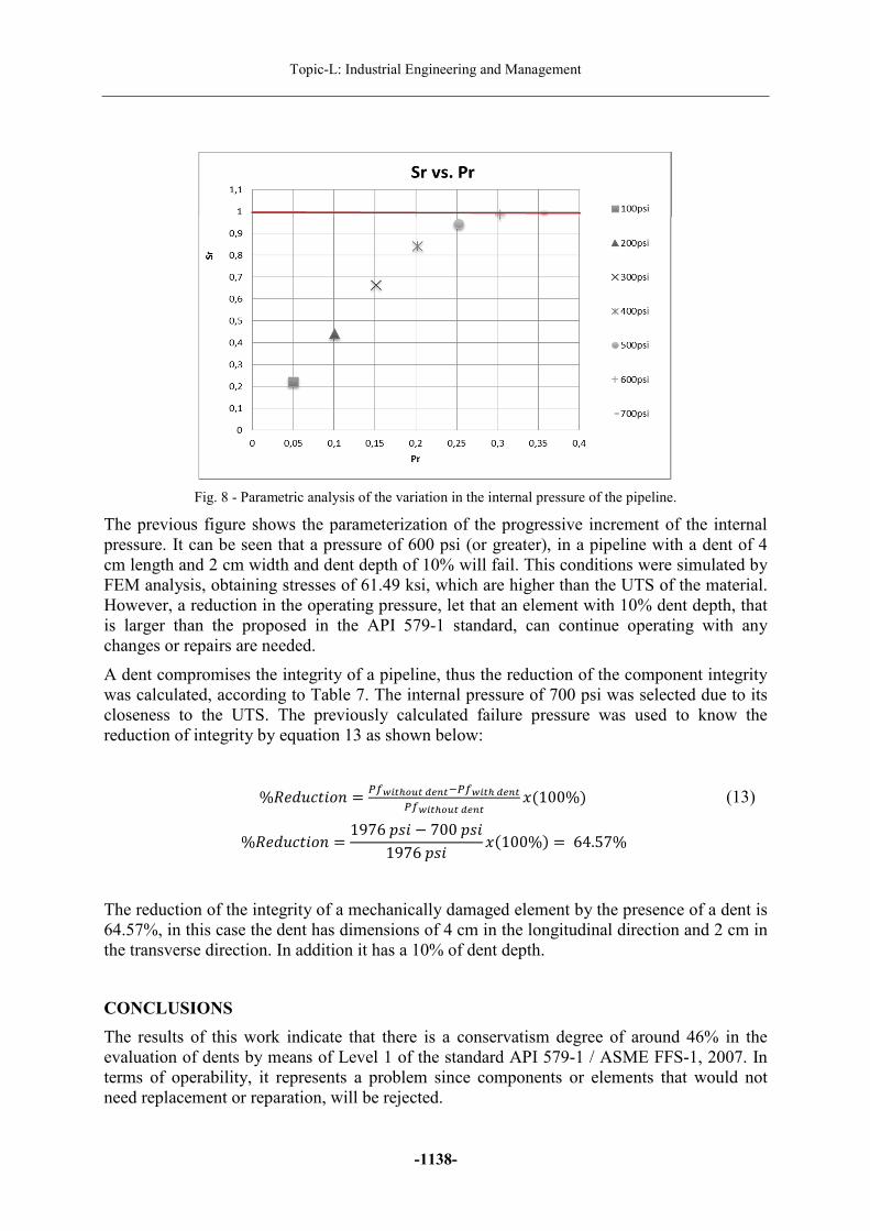
The Pr parameter was used to know when the component would fail due to the presence of a mechanical damage. This parameter shows how the integrity of the pipeline is affected and is calculated from the applied pressure (Pa) divided by the failure pressure (Pf), giving a dimensionless number, as set in equation 12. The ratio of the stresses against the progressive increase of the load on the axis of the abscissa is obtained, as shown in Figure 8.
TV � �D�o (12)
API 579-1
Topic-L: Industrial Engineering and Management
-1138-
Fig. 8 - Parametric analysis of the variation in the internal pressure of the pipeline.
The previous figure shows the parameterization of the progressive increment of the internal pressure. It can be seen that a pressure of 600 psi (or greater), in a pipeline with a dent of 4 cm length and 2 cm width and dent depth of 10% will fail. This conditions were simulated by FEM analysis, obtaining stresses of 61.49 ksi, which are higher than the UTS of the material. However, a reduction in the operating pressure, let that an element with 10% dent depth, that is larger than the proposed in the API 579-1 standard, can continue operating with any changes or repairs are needed.
A dent compromises the integrity of a pipeline, thus the reduction of the component integrity was calculated, according to Table 7. The internal pressure of 700 psi was selected due to its closeness to the UTS. The previously calculated failure pressure was used to know the reduction of integrity by equation 13 as shown below:
%pf��qi�eW � �UrGstJNsIuEsK�UrGstIuEs�UrGstJNsIuEs
�(100%) (13)
%pf��qi�eW � 1976��� − 700���1976��� �(100%) � 64.57%
The reduction of the integrity of a mechanically damaged element by the presence of a dent is 64.57%, in this case the dent has dimensions of 4 cm in the longitudinal direction and 2 cm in the transverse direction. In addition it has a 10% of dent depth.
CONCLUSIONS
The results of this work indicate that there is a conservatism degree of around 46% in the evaluation of dents by means of Level 1 of the standard API 579-1 / ASME FFS-1, 2007. In terms of operability, it represents a problem since components or elements that would not need replacement or reparation, will be rejected.
Proceedings of the 7th International Conference on Mechanics and Materials in Design
-1139-
Derived from the study carried out:
1. The dent depth is not the only determining factor for assessing the severity of the damage. It is also important to consider the width and length of the dent, as well as the system pressure.
2. The acceptance limit of a dent can be greater than 7% of the outside pipe diameter, in contrast to stablished by the API 579-1 standard. The results of this work indicate that the acceptance limit is around 13% of depth.
3. The increase pressure tests indicate that the reduction of the integrity of a component as a result of the presence of a dent might be 64.57%.
4. Based on the results of the FEM simulations, it is established that the zone in which the failure initiates are the ending opposite sides on the major axis of the dent.
ACKNOWLEDGMENTS
The authors would like to acknowledge to the National Polytechnic Institute (IPN), the National Council of Science and Technology (CONACYT) and the Analysis Integrity of Pipelines Group (GAID-IPN) for the support to carry out this research.
REFERENCES
[1]-Lyon D. WESTERN EUROPEAN CROSS-COUNTRY OIL PIPELINES 30-YEAR PERFORMANCE STATISTICS. Report No. 1/02, CONCAWE, Brussels; 2002.
[2]-AN ASSESSMENT OF MEASURES IN USE FOR GAS PIPELINES TO MITIGATE AGAINST DAMAGE CAUSED BY THIRD PARTY ACTIVITY. Contract research report 372/2001. 2001. HSE Books. Her Majesty´s Stationary Office UK. Recovered from www.hse.gov.uk
[3]-Fitness-For-Service, API 579-1/ASME FFS-1, June 5, 2007. Part 12 ASSESSMENT OF DENTS, GOUGES AND DENT-GOUGE COMBINATIONS, 2nd Edition.
[4]-Kyriakides, S., Corona, E., 2007. MECHANICS OF OFFSHORE PIPELINES: Volume 1 Buckling and Collapse, vol. 1. Elsevier.
[5]-N. Rathinam y B. Prabu. NUMERICAL STUDY ON INFLUENCE OF DENT PARAMETERS ON CRITICAL BUCKLING PRESSURE OF THIN CYLINDRICAL SHELL SUBJECTED TO UNIFORM LATERAL PRESSURE. Department of Mechanical Engineering, Pondicherry Engineering College, Puducherry 605014, India (19 November 2014). Thin-Walled Structures 88 (2015) 1-15.
[6]-S.Saad-Elden, Y.Garbatov, C. y Guedes Soares. STRESS-STRAIN ANALYSIS OF DENTED RECTANGULAR PLATES SUBJECTED TO UNI-AXIAL COMPRESSIVE LOADING. Centre for Marine Technology and Ocean Engineering (CENTEC), Instituto Superior Técnico, Universidad de Lisboa, Av Rovisco País, 1049-001 Lisboa, Portugal (22 April 2015). Engineering Structures 99 (2015) 78-91.

Topic-L: Industrial Engineering and Management
-1140-
[7]-Ying Wu, Na Tang y Peng Zhang. THE COMPARISON OF DENTED PIPELINE DISPLACEMENT CALCULATION METHODS, Department of civil Engineering and Architecture, Southwest Petroleum University, Chengdu 610500, China (13 June 2015). Engineering Failure Analysis 57 (2015) 562-573.
[8]-Hopkins H., Palmer A. and Associates (APA). 2005. COMO EVALUAR DESGARRES E IDENTACIONES. Pespen Group Ltd, Inglaterra.
[9]-Ing. Ángel Giovanni Islas Garrido. ANÁLISIS EXPERIMENTAL DE ESFUERZOS EN TUBOS CON ABOLLADURAS SUJETOS A PRESIÓN INTERNA (Master's Thesis). Distrito federal, México, Instituto Politécnico Nacional, Escuela Superior de Ingeniería química e industrias extractivas, January 2009.
[10]-Norma Oficial Mexicana NOM-027-SESH-2010, ADMINISTRACIÓN DE LA INTEGRIDAD DE DUCTOS DE RECOLECCIÓN Y TRANSPORTE DE HIDROCARBUROS.
[11]-G. Latorre, R. Mora, F. Mejía U., A. Martínez y R. Suárez. ANÁLISIS ESTRUCTURAL DE TUBERÍAS DE OLEODUCTOS ABOLLADAS POR CARGA EXPLOSIVA. Ciencia, Tecnología y Futuro, volume 1 number 4, Diciembre 1998. pp. 101-110.
[12]-Ángel M. Pérez Sarmiento, Juan A. Lara Magallanes y Jesús H. García. APPLICATION OF THE FITNESS FOR SERVICE METHODOLOGY IN THE CASE OF AN ACID GAS DISCHARGE SEPARATOR, Pan American Conference for NDT (5°, 2011, Cancun, México). Department of Mechanical Integrity, Corporación Mexicana de Investigación en Materiales, S.A. de C.V.
[13]-B. Pinheiro, I. Pasqualino y S. Cunha. FATIGUE LIFE ASSESSMENT OF DAMAGE PIPELINES UNDER CYCLIC INTERNAL PRESSURE: PIPELINES WITH LONGITUDINAL AND TRANSVERSE PLAIN DENTS. Subsea Technology Laboratory (LTS), Ocean Engineering Department, COPPE/Federal University of Rio de Janeiro, PO Box 68508, Cidade Universitária, CEP 21941-909 Rio de Janeiro/RJ, Brazil (12 June 2014). International Journal of Fatigue 68 (2014) 38-47.
[14]-Ing. Jesús Zarate Nevarez. ANÁLISIS DEL RIESGO DE ROTURA EN SERVICIO DE TUBERÍAS DE GAS NATURAL (Master Thesis). Distrito Federal, México, Instituto Politécnico Nacional, Escuela Superior de Ingeniería Mecánica y Eléctrica Zacatenco, 2009.
[15]-M. Zeinoddini, M. Ezzati y G.A.R. Parke. PLASTIC BUCKLING, WRINKLING AND COLLAPSE BEHAVIOR OF DENTED X80 STEEL LINE PIPES UNDER AXIAL COMPRESSION. Department of Civil Engineering, K.N Toosi University of Technology, Tehran, Iran (5 September 2015). Journal of Loss Prevention in the process Industries 38 (2015) 67-78.
[16]-Vidal Miguel Barquín Aja. ANÁLISIS DEL RIESGO DE ROTURA EN SERVICIO DE TUBERÍAS DE GAS NATURAL (Engineering thesis). Cantabria, España, Universidad de Cantabria, Escuela Técnica Superior de Ingenieros Industriales y de Telecomunicación, March 2014.