determination of beta-factors for safety instrumented systems · 2017-01-22 · safety instrumented...
TRANSCRIPT

Determination of Beta-factors for Safety Instrumented Systems
Wenjing Sun
Reliability, Availability, Maintainability and Safety (RAMS)
Supervisor: Marvin Rausand, IPK
Department of Production and Quality Engineering
Submission date: June 2013
Norwegian University of Science and Technology


RAMSReliability, Availability,
Maintainability, and Safety
Determination of Beta-factor forSafety Instrumented Systems
Wenjing Sun
June 2013
MASTER THESIS
Department of Production and Quality EngineeringNorwegian University of Science and Technology
Main supervisor: Marvin Rausand
Co-supervisor: Yiliu Liu


Preface
This Master thesis is written in the international program of Reliability, Availabil-ity, Maintainability, and Safety (RAMS) at Norwegian University of Science andTechnology (NTNU) during the spring semester of 2013. The topic of the thesisis Determination of Beta-factor for Safety Instrumented Systems. The responsiblesupervisor of the subject have been Marvin Rausand and Yiliu Liu.
Safety instrumented systems are very important for process industries to ef-fectively prevent hazardous events from developing into accidents. In safety in-strumented systems, there are still many kinds of failures that could could result inaccidents. Common cause failures play a big part of contributing to many majoraccidents, which could lead to a serious consequence. For example, the offshoredrilling rig accident occurred in 1982 which result in the entire 84 man crew onthe rig die. Although common cause failures are mentioned in OREDA (2002)related to fire and gas detectors, there is no guidance on how to collect the data ofcommon cause failures. For now, it is impossible to avoid common cause failures.The only thing we can do is to reduce common cause failures as many as possible.
The whole master thesis is divided into three parts. The first part is a briefintroduction of safety instrumented systems. The second part is an introductionof common cause failures. The last part contains an introduction, an analysis anda comparison of three methods used to determine β-factor for SIS: IEC 61508checklist, IEC 62061 checklist and unified partial method.
Trondheim, June 2013
Wenjing Sun
Signature
i


Acknowledgment
I would like to thank my supervisor Professor Rausand, from the Department ofProduction and Quality Engineering at NTNU, for giving me very useful advice ofselecting the topic of the master thesis. Because I wrote about SIL in Operation formy project thesis last semester, I was unsure whether it is a good idea to continuethis topic for my master thesis. After the discussion, Professor Rausand analyzedmy situation and gave me a good idea about how to decide the topic. Finally, Idecided to write about one of the common cause failure factors which is β-factor,which is also related to the project written in the last semester. Also, ProfessorRausand provided me with some very useful materials about my master thesis.Besides, I am grateful for Professor Rausand’s precious time to help me with allthe problems that I encouraged during the process of writing my master thesis.
I also would like to thank my co-supervisor Yiliu Liu from the Department ofProduction and Quality Engineering at NTNU, for his helpful supports, invaluableadvices and quick feedback on my work. Whenever I meet tough questions, healways helps me and keeps my spirits up.
Overall, I strongly believe the quality of the thesis has improved significantlywith all their helps.
W.S.
iii


Summary
Safety instrumented systems are vital safety barriers to reduce the probability ofthe hazardous events and mitigate the consequences. Safety instrumented systemshave been widely used in many kinds of industries. Redundancy is often intro-duced in safety instrumented systems for higher reliability. Although redundancyhas many benefits, the negative effects cannot be ignored. Redundancy inducescommon cause failures to safety instrumented systems. The common cause fail-ures are a big threat to the reliability of systems, which contributes to many majoraccidents. Therefore, it is very important to take common cause failures into con-sideration in risk and reliability assessment for the whole life cycle, especially inthe design phase.
There are two common cause failure modeling methods: explicit modelingand implicit modeling. The Beta-factor model belongs to implicit modeling and itis the simplest and widely used model. Many common cause failure models havebeen developed based on the beta-factor model. Three methods for the determi-nation of beta-factor demonstrated in this master thesis: two IEC checklists (IEC61508-6 and IEC 62061) and unified partial method (UPM). The procedures forbeta-factor determination of these three methods are presented, the critical evalu-ation is performed for the IEC 61508-6 checklist, discussions on the effectivenessof questions are conducted, and a recommended question list of IEC 61508 is pro-vided. Next, a detailed comparison between two checklists (IEC 61508-6 and IEC62061) is carried out. As well the comparison between the checklist methods andthe unified partial method is also demonstrated. Finally, some suggestions for thefurther work are provided at the end of this master thesis.
v

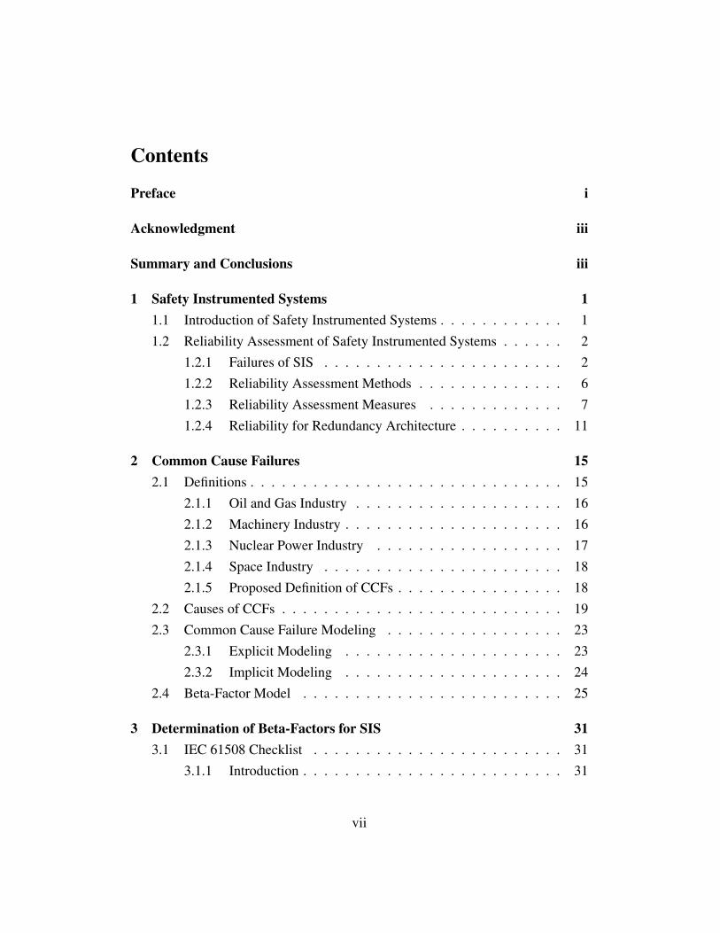
Contents
Preface i
Acknowledgment iii
Summary and Conclusions iii
1 Safety Instrumented Systems 11.1 Introduction of Safety Instrumented Systems . . . . . . . . . . . . 11.2 Reliability Assessment of Safety Instrumented Systems . . . . . . 2
1.2.1 Failures of SIS . . . . . . . . . . . . . . . . . . . . . . . 21.2.2 Reliability Assessment Methods . . . . . . . . . . . . . . 61.2.3 Reliability Assessment Measures . . . . . . . . . . . . . 71.2.4 Reliability for Redundancy Architecture . . . . . . . . . . 11
2 Common Cause Failures 152.1 Definitions . . . . . . . . . . . . . . . . . . . . . . . . . . . . . . 15
2.1.1 Oil and Gas Industry . . . . . . . . . . . . . . . . . . . . 162.1.2 Machinery Industry . . . . . . . . . . . . . . . . . . . . . 162.1.3 Nuclear Power Industry . . . . . . . . . . . . . . . . . . 172.1.4 Space Industry . . . . . . . . . . . . . . . . . . . . . . . 182.1.5 Proposed Definition of CCFs . . . . . . . . . . . . . . . . 18
2.2 Causes of CCFs . . . . . . . . . . . . . . . . . . . . . . . . . . . 192.3 Common Cause Failure Modeling . . . . . . . . . . . . . . . . . 23
2.3.1 Explicit Modeling . . . . . . . . . . . . . . . . . . . . . 232.3.2 Implicit Modeling . . . . . . . . . . . . . . . . . . . . . 24
2.4 Beta-Factor Model . . . . . . . . . . . . . . . . . . . . . . . . . 25
3 Determination of Beta-Factors for SIS 313.1 IEC 61508 Checklist . . . . . . . . . . . . . . . . . . . . . . . . 31
3.1.1 Introduction . . . . . . . . . . . . . . . . . . . . . . . . . 31
vii
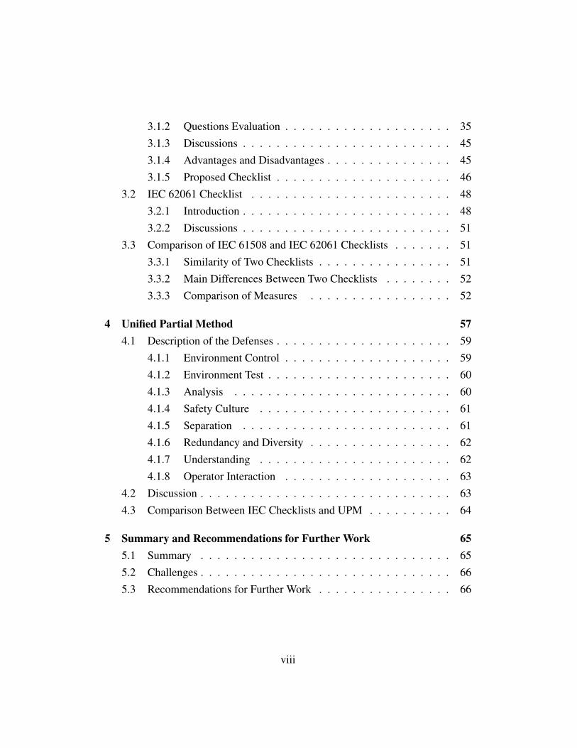
3.1.2 Questions Evaluation . . . . . . . . . . . . . . . . . . . . 353.1.3 Discussions . . . . . . . . . . . . . . . . . . . . . . . . . 453.1.4 Advantages and Disadvantages . . . . . . . . . . . . . . . 453.1.5 Proposed Checklist . . . . . . . . . . . . . . . . . . . . . 46
3.2 IEC 62061 Checklist . . . . . . . . . . . . . . . . . . . . . . . . 483.2.1 Introduction . . . . . . . . . . . . . . . . . . . . . . . . . 483.2.2 Discussions . . . . . . . . . . . . . . . . . . . . . . . . . 51
3.3 Comparison of IEC 61508 and IEC 62061 Checklists . . . . . . . 513.3.1 Similarity of Two Checklists . . . . . . . . . . . . . . . . 513.3.2 Main Differences Between Two Checklists . . . . . . . . 523.3.3 Comparison of Measures . . . . . . . . . . . . . . . . . 52
4 Unified Partial Method 574.1 Description of the Defenses . . . . . . . . . . . . . . . . . . . . . 59
4.1.1 Environment Control . . . . . . . . . . . . . . . . . . . . 594.1.2 Environment Test . . . . . . . . . . . . . . . . . . . . . . 604.1.3 Analysis . . . . . . . . . . . . . . . . . . . . . . . . . . 604.1.4 Safety Culture . . . . . . . . . . . . . . . . . . . . . . . 614.1.5 Separation . . . . . . . . . . . . . . . . . . . . . . . . . 614.1.6 Redundancy and Diversity . . . . . . . . . . . . . . . . . 624.1.7 Understanding . . . . . . . . . . . . . . . . . . . . . . . 624.1.8 Operator Interaction . . . . . . . . . . . . . . . . . . . . 63
4.2 Discussion . . . . . . . . . . . . . . . . . . . . . . . . . . . . . . 634.3 Comparison Between IEC Checklists and UPM . . . . . . . . . . 64
5 Summary and Recommendations for Further Work 655.1 Summary . . . . . . . . . . . . . . . . . . . . . . . . . . . . . . 655.2 Challenges . . . . . . . . . . . . . . . . . . . . . . . . . . . . . . 665.3 Recommendations for Further Work . . . . . . . . . . . . . . . . 66
viii
1 Safety Instrumented Systems
1.1 Introduction of Safety Instrumented Systems
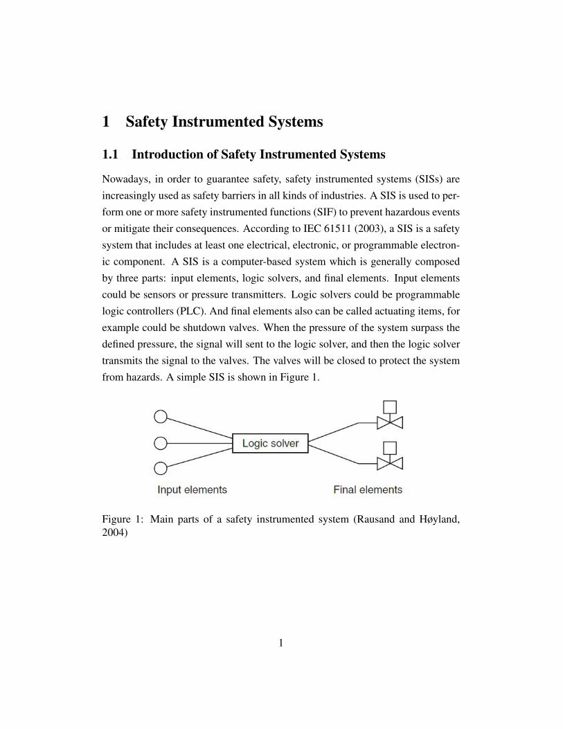
Nowadays, in order to guarantee safety, safety instrumented systems (SISs) areincreasingly used as safety barriers in all kinds of industries. A SIS is used to per-form one or more safety instrumented functions (SIF) to prevent hazardous eventsor mitigate their consequences. According to IEC 61511 (2003), a SIS is a safetysystem that includes at least one electrical, electronic, or programmable electron-ic component. A SIS is a computer-based system which is generally composedby three parts: input elements, logic solvers, and final elements. Input elementscould be sensors or pressure transmitters. Logic solvers could be programmablelogic controllers (PLC). And final elements also can be called actuating items, forexample could be shutdown valves. When the pressure of the system surpass thedefined pressure, the signal will sent to the logic solver, and then the logic solvertransmits the signal to the valves. The valves will be closed to protect the systemfrom hazards. A simple SIS is shown in Figure 1.
Figure 1: Main parts of a safety instrumented system (Rausand and Høyland,2004)
1

1.2 Reliability Assessment of Safety Instrumented Systems
To ensure the reliability of SIS, it is very important for reliability engineers toidentify whether the status of all the elements are functioning or not functioningin a functional block. However, all potential failures in SIS should be identifiedfirst.
1.2.1 Failures of SIS
For now, there is no way to identify all the potential failures because of the factthat there are too many types of failure modes. Therefore, we can classify failuresbased on different causes.
There are various ways to classify failures. Generally, failures can be classi-fied based on the causes of failure and the effects of failure (Lundteigen, 2006).Rausand (2010) divides failures into two categories based on the failure effects:
• Dangerous failure
failure of an element and/or subsystem and/or system that plays apart in implementing the safety function that:
a) prevents a safety function from operating when required (de-mand mode) or causes a safety function to fail (continuous mode)such that the EUC is put into a hazardous or potentially hazardousstate; or
b) decreases the probability that the safety function operates cor-rectly when required
• Safe failure
failure of an element and/or subsystem and/or system that plays apart in implementing the safety function that:
a) results in the spurious operation of the safety function to putthe EUC (or part thereof) into a safe state or maintain a safe state; or
2

b) increases the probability of the spurious operation of the safetyfunction to put the EUC (or part thereof) into a safe state or maintaina safe state
In short, dangerous failures will cause damages or hazards in a system. In contrast,safe failures are failures that will not cause any damages or will not make thesystem fail.
Since the safe failures do not lead to major disabling of the system’s function-ing ability as required, sometimes only dangerous failures are taken into consid-eration. Dangerous failures can be further divided into:
• Dangerous detected (DD) failure
DD failures are the failures that will be detected immediately after it occurs.
• Dangerous undetected (DU) failure
DU failures are hidden failures that are only revealed by diagnostic test.Safe failure can be comprised by
• Safe detected (SD)
SD failures are detected by automatic self-testing.
• Safe undetected (SU)
SU failures cannot be detected by automatic regular self-testing.The classification of failure modes is shown in Figure 2.
3

Figure 2: failure classification based on the causes of failures (Rausand, and Høy-land, 2004)
IEC 61508 (2010) classified failures into random hardware failure and sys-tematic failure based on the causes of failure. Random hardware failure can alsobe called physical failure. While systematic failure is nonphysical failure. Thefailure classification proposed by IEC 61508 is illustrated in Figure 3.
Figure 3: Possible failure classification by cause of failure (IEC 61508, 2010)
Random hardware failure:
A failure, occurring at a random time, which results from one ormore of the possible degradation mechanisms in the hardware. (IEC61508, 2010)
4

Random hardware failure can further be divided into aging failure and stress fail-ure. Aging failures are failures occurring because of design scope. Stress failuresare failures that occur due to excessive stress on the item, which may be causedby human error when operating. (Rausand, 2004.)
Systematic failure:
A failure, related in a deterministic way to a certain cause, whichcan only be eliminated by a modification of the design or of the man-ufacturing process, operational procedures, documentation or otherrelevant factors. (IEC 61508, 2010)
The overall failure classification scheme is illustrated in Figure 4 based on thebow-tie structure.
Figure 4: failure classification scheme (adopted from Lundteigen, 2006)
The PDS method (Hauge, 2010) also uses the same classification with IEC61508, but the excessive stress failure is included in systematic failure insteadof random hardware failure. The detailed failure classification illustrated in PDSmethod is shown in Figure 5.
5
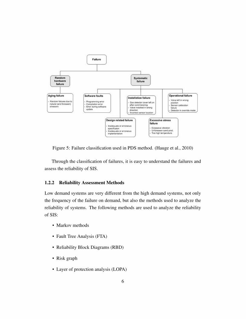
Figure 5: Failure classification used in PDS method. (Hauge et al., 2010)
Through the classification of failures, it is easy to understand the failures andassess the reliability of SIS.
1.2.2 Reliability Assessment Methods
Low demand systems are very different from the high demand systems, not onlythe frequency of the failure on demand, but also the methods used to analyze thereliability of systems. The following methods are used to analyze the reliabilityof SIS:
• Markov methods
• Fault Tree Analysis (FTA)
• Reliability Block Diagrams (RBD)
• Risk graph
• Layer of protection analysis (LOPA)
6

Markov method can be a qualitative or a quantitative method. It is suitable forsmall but complex systems with dynamic properties. After understanding the sys-tem, transaction diagram can be built; therefore, it helps to understand how thesystem operates. The limitation of this method is that it only applies on smallsystems. Besides, the failure rate is required to be constant.
A fault tree is a top-down logic diagram which is formed by OR gates andAND gates to display the relationship between events in a system. The basicevents are the events located at the lowest level. Normally, the basic events arecomponent failures, human errors or environment conditions. Fault tree analy-sis can be qualitative or quantitative, and sometimes it could be qualitative andquantitative. In contrast to Markov analysis, fault tree analysis is not suitable foranalyzing dynamic systems. However, it has been widely used in many applica-tion areas. Besides, it is suitable to analyze large and complex systems.
A fault tree can always be converted to reliability block diagram. Also, reli-ability block diagrams can always be converted to fault trees. According to Rau-sand (2011), a reliability diagram shows the logical connections of functioningitems that are needed to fulfill a specified system function. In a block diagram, ifa function could go though from the start to the end, then we say that the item isfunctioning.
Risk graph and LOPA are qualitative methods. Fault tree analysis and reli-ability block diagrams are usually used for low-demand systems, while Markovmethod is suitable for high-demand systems.
1.2.3 Reliability Assessment Measures
To assess the reliability of SISs, the concept of safety integrity level (SIL) is in-troduced.
Based on the Business Dictionary , the definition of the reliability is
the ability of an apparatus, machine, or system to consistentlyperform its intended or required function or mission, on demand andwithout degradation or failure.
7
Safety integrity is the probability that the safety related systems perform the re-quired safety function in a defined period of time under all kinds of conditions.The reliability of SIS is measured by SIL. The definition of SIL from IEC 61508(2010) is
Discrete level (one out of a possible four), corresponding to arange of safety integrity values, where safety integrity level 4 has thehighest level of safety integrity and safety integrity level 1 has thelowest.
SIL is a measure of the reliability of SIS, which is divided into four classes accord-ing to the probability of failure on demand (PFD). PFD is the average proportionof time the item is not performing its intended functioning, which is used in lowdemand operation mode. SIL is showed by probability of failure per hour (PFH)when it used in high demand mode or continuous mode.
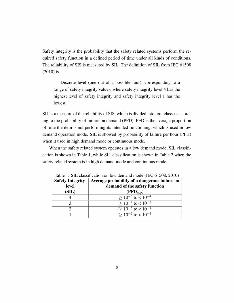
When the safety related system operates in a low demand mode, SIL classifi-cation is shown in Table 1, while SIL classification is shown in Table 2 when thesafety related system is in high demand mode and continuous mode.
Table 1: SIL classification on low demand mode (IEC 61508, 2010)Safety Integrity Average probability of a dangerous failure on
level demand of the safety function(SIL) (PFDavg)
4 ≥ 10−5 to < 10−4
3 ≥ 10−4 to < 10−3
2 ≥ 10−3 to < 10−2
1 ≥ 10−2 to < 10−1
8

Table 2: SIL classification on high demand mode (IEC 61508, 2010)Safety Integrity Average probability of a dangerous failure of
level the safety function[h−1]
(SIL) (PFH)4 ≥ 10−9 to < 10−8
3 ≥ 10−8 to < 10−7
2 ≥ 10−7 to < 10−6
1 ≥ 10−6 to < 10−5
PFD PFD is normally calculated to measure the quality of SIF. Both standardIEC 61508 and IEC 61511 use SIL as a measure to assess the reliability of SIS.SIL is obtained and classified by the value of PFD, which has been introduced.When PFD is used for low-demand systems, it can be obtained from the followingequation:
PFD = 1− 1τ
ˆτ
0R(t)dt
Normally the failure which is considered for PFD calculation is DU failure.For a single component, the survivor function is
R(t) = e−λDU t
Therefore,
PFD = 1− 1τ
ˆτ
0R(t)dt
= 1− 1τ
ˆτ
0e−λDU tdt
PFD = 1− 1λDUτ
(1− e−λDUτ)
9
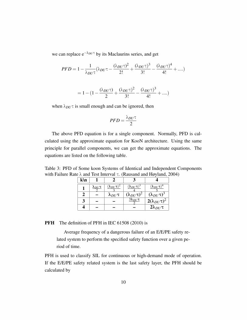
we can replace e−λDUτ by its Maclaurins series, and get
PFD = 1− 1λDUτ
(λDUτ−(λDUτ)2
2!+
(λDUτ)3
3!− (λDUτ)
4
4!+ ....)
= 1− (1− (λDUτ)2
+(λDUτ)
2
3!− (λDUτ)
3
4!+ ....)
when λDUτ is small enough and can be ignored, then
PFD =λDUτ
2
The above PFD equation is for a single component. Normally, PFD is cal-culated using the approximate equation for KooN architecture. Using the sameprinciple for parallel components, we can get the approximate equations. Theequations are listed on the following table.
Table 3: PFD of Some koon Systems of Identical and Independent Componentswith Failure Rate λ and Test Interval τ. (Rausand and Høyland, 2004)
k\n 1 2 3 4
1 λDUτ2
(λDUτ)2
3(λDUτ)
3
4(λDUτ)
4
52 – λDUτ (λDUτ)2 (λDUτ)3
3 – – 3λDUτ2 2(λDUτ)2
4 – – – 2λDUτ
PFH The definition of PFH in IEC 61508 (2010) is
Average frequency of a dangerous failure of an E/E/PE safety re-lated system to perform the specified safety function over a given pe-riod of time.
PFH is used to classify SIL for continuous or high-demand mode of operation.If the E/E/PE safety related system is the last safety layer, the PFH should becalculated by
10

F(T ) = 1−R(t)
which is the unreliability of the system. And if the E/E/PE safety related systemis not the ultimate safety layer, then the PFH should be calculated by
PFH =1
MT BF
which is the unavailability of the system. MTBF is the abbreviation of meantime between failure.
To calculate PFH for a safety-instrumented system, use the following formulain IEC 61508
PFHSY S = PFHS +PFHLS +PFHFE
S, LS, and FE represent the three parts of a safety instrumented system.
S means sensors in a safety-instrumented system;
LS means logic solvers in a safety-instrumented system;
FE means final elements in a safety-instrumented system, like valves.
1.2.4 Reliability for Redundancy Architecture
To improve the reliability of SIS, redundant components are introduced to makesure the system works if single components fail.
Redundancy: The provision of one or more additional measures,usually identical, to provide fault tolerance. (IEC 61508, 2010)
There are two kinds of redundancy in SIS. Redundant components could be usedin parallel with the single components and then share the load, which is called
11

active redundancy. Also, the redundant components can be in standby position,which can be active only if the single components fail. This kind of redundancycalled passive redundancy.
Although redundancy prevents independent failures and improves the reliabil-ity of SIS, it may lead to CCFs because coupling factors will link more than twoseparate channels in a multiple channel. CCFs are failures that more than twocomponents fail and share the same cause. CCF is a kind of dependent failures.The definition of dependent failures is shown in Table 4.
Table 4: Definition of dependent failure (Rausand and Høyland, 2004)Dependent Failure The probability of a group of events
which probabilities cannot be expressedas a simple product of unconditionalprobability of failure of single components.
Common This is a kind of dependent failure whichCause occurs in redundant components in whichFailure a single common cause - simultaneously
or near simultaneously leads to failuresin different channels.
Common This definition applies to failures ofModel common causes in which multiple elementsFailure fail similarly in the same mode.
Cascade These are all dependent failures that doFailure not share a common cause, meaning they
do not affect redundant components.Additionally:The definition of dependent failures“ includes all definitions of failures that arenot independent. This definition of dependent failures clearly implies that anindependent failure in a group of events can be expressed as a simple productof conditional probabilities of failures of a single event.
CCF is a part of dependent failure, while common model failure (CMF) is apart of CCFs. In this master thesis, we only focus on CCFs.
CCF is a serious threat to SIS reliability (Edwards and Waston, 1979). CCFscontribute to many major accidents, which has major negative impacts. For ex-
12

ample, offshore drilling rig accident occurred in 1982. The entire 84 man crew onthe rig was lost. The CCF is a total loss of ballast control and of stability (Rau-sand, 2011). Although CCFs are mentioned in OREDA (2002) related to fire andgas detectors, there is no guidance on how to collect CCFs data. For now, it isimpossible to avoid CCFs. Hence, what we can do is to reduce common cause asmany as possible. In the next chapter, we will present the detailed definitions ofCCFs and the assessment methods.
13


2 Common Cause Failures
2.1 Definitions
IEC 61508 is widely used in Oil & Gas companies, which is the basic standardfor industries to develop their own standards. The standards developed based onIEC 61508 are shown in the Figure 6.
Figure 6: Standards for safety instrumented systems (Jin, 2012)
Although CCFs are taken into consideration during risk and reliability assess-ment for many years, there is no unified definition for industries, since differentauthors and engineers in different areas hold different ideas.
Wetherholt (2011) demonstrates a simple definition of a common cause fail-ure:
A failure of two or more components, system, or structures due toa single specific event or cause.
A more complex definition is
15

An event or cause which bypasses or invalidates redundancy orindependence, i.e., an event which causes the simultaneous loss ofredundant or independent items which may or may not include inad-vertent operation, or an unintended cascading effect from other oper-ations or failure within the system.
In next section, definitions of CCF in different industries will be reviewed.
2.1.1 Oil and Gas Industry
Based on the standard IEC 61508, CCF is defined as
A failure that is the result of one or more events, causing concur-rent failures of two separate channels in a multiple channel system,leading to system failure.
In this definition, the description of “concurrent failures of two separate chan-nels in a multiple channel system” and “leading to system failure”cannot be usedtogether in some conditions. For example, in 2oo3 or 2oo4 configuration, two sep-arate channels failing at the same time are not belong to CCFs because the systemis still functioning. Redundancy is widely used in safety instrumented systems toimprove the reliability of the system. Meanwhile, redundant components exposesthe system into CCFs. Therefore, the description of CCF in IEC 61508 cannot beused for KooN structure.
The standard is mainly used for Oil & Gas industry and process industry;therefore, this definition is the same with the one used in the standard IEC 61511which is used for process industry.
2.1.2 Machinery Industry
According to the standard BS EN ISO 12100:2010, CCFs in the machinery indus-try is defined as
16
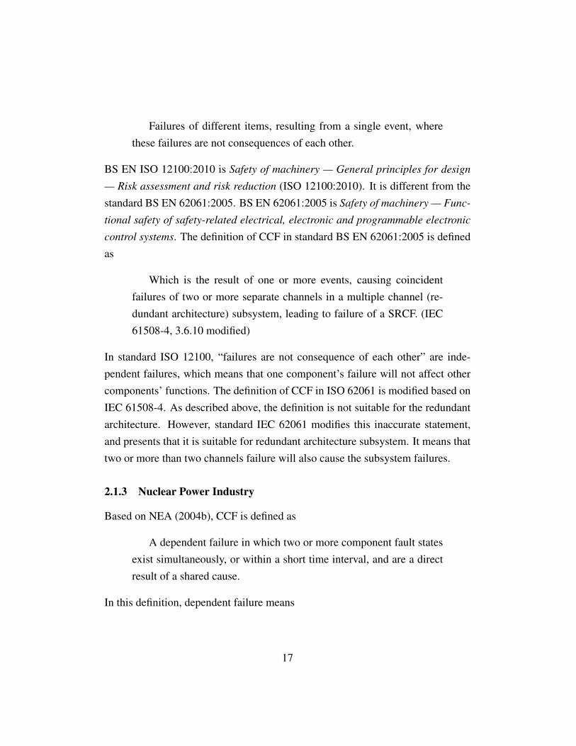
Failures of different items, resulting from a single event, wherethese failures are not consequences of each other.
BS EN ISO 12100:2010 is Safety of machinery — General principles for design
— Risk assessment and risk reduction (ISO 12100:2010). It is different from thestandard BS EN 62061:2005. BS EN 62061:2005 is Safety of machinery — Func-
tional safety of safety-related electrical, electronic and programmable electronic
control systems. The definition of CCF in standard BS EN 62061:2005 is definedas
Which is the result of one or more events, causing coincidentfailures of two or more separate channels in a multiple channel (re-dundant architecture) subsystem, leading to failure of a SRCF. (IEC61508-4, 3.6.10 modified)
In standard ISO 12100, “failures are not consequence of each other” are inde-pendent failures, which means that one component’s failure will not affect othercomponents’ functions. The definition of CCF in ISO 62061 is modified based onIEC 61508-4. As described above, the definition is not suitable for the redundantarchitecture. However, standard IEC 62061 modifies this inaccurate statement,and presents that it is suitable for redundant architecture subsystem. It means thattwo or more than two channels failure will also cause the subsystem failures.
2.1.3 Nuclear Power Industry
Based on NEA (2004b), CCF is defined as
A dependent failure in which two or more component fault statesexist simultaneously, or within a short time interval, and are a directresult of a shared cause.
In this definition, dependent failure means
17
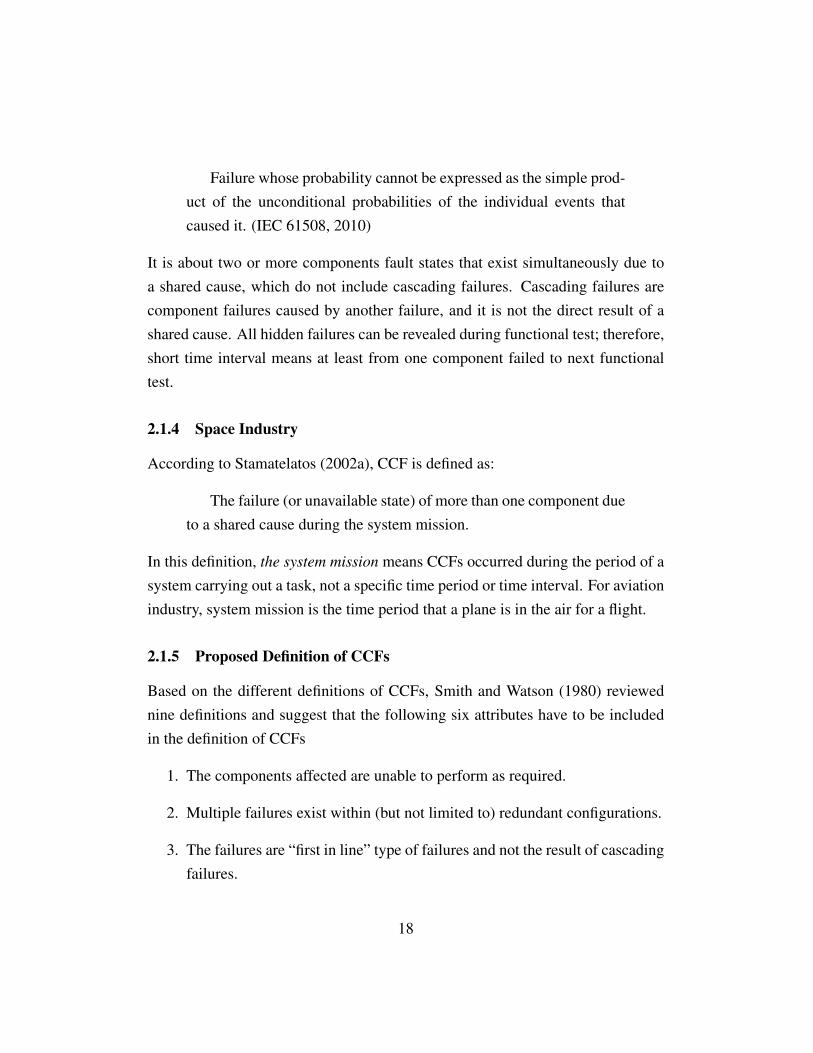
Failure whose probability cannot be expressed as the simple prod-uct of the unconditional probabilities of the individual events thatcaused it. (IEC 61508, 2010)
It is about two or more components fault states that exist simultaneously due toa shared cause, which do not include cascading failures. Cascading failures arecomponent failures caused by another failure, and it is not the direct result of ashared cause. All hidden failures can be revealed during functional test; therefore,short time interval means at least from one component failed to next functionaltest.
2.1.4 Space Industry
According to Stamatelatos (2002a), CCF is defined as:
The failure (or unavailable state) of more than one component dueto a shared cause during the system mission.
In this definition, the system mission means CCFs occurred during the period of asystem carrying out a task, not a specific time period or time interval. For aviationindustry, system mission is the time period that a plane is in the air for a flight.
2.1.5 Proposed Definition of CCFs
Based on the different definitions of CCFs, Smith and Watson (1980) reviewednine definitions and suggest that the following six attributes have to be includedin the definition of CCFs
1. The components affected are unable to perform as required.
2. Multiple failures exist within (but not limited to) redundant configurations.
3. The failures are “first in line” type of failures and not the result of cascadingfailures.
18

4. The failures occur within a defined critical time interval (e.g., the time aplane is in the air during a flight).
5. The failures are due to a single underlying defect or a physical phenomenon(the common cause of failures).
6. The effect of failures must lead to some major disabling of the system’sability to perform as required.
The first attribute presents that CCF has lead to the components failure and isunable to perform the required function. The second attribute presents that mul-tiple failures can exist within a KooN architecture, which modified the unclearstatement in standard IEC 61508. For the third attribute, “first in line” means thefailure is caused by the root cause like human error, environment, not affected bythe other component’s failure. In other words, first in line failures means indepen-dent failures, and cascading failures are not included in this definition. The fourthattribute shows the time interval for the occurring of CCFs, which is a definedcritical time interval. Critical time interval is different in different systems. ForSIS, time interval means the time period between two functional tests for a samesystem. However, for aviation industry, the critical time interval is the plane in theair for one mission.
According to these six attributes, the definition of CCF is given by Smith andWatson (1980):
Inability of multiple, first-in-line items to perform as required in adefined critical time period due to a single underlying defect or phys-ical phenomena such that the end effect is judged to be a loss of oneor more systems.
2.2 Causes of CCFs
Based on Rausand (2011), Causes of CCFs are classified into two categories:
• Root cause
19
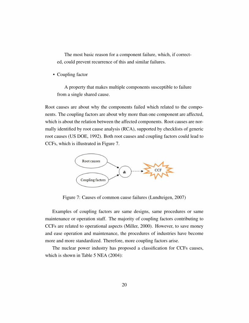
The most basic reason for a component failure, which, if correct-ed, could prevent recurrence of this and similar failures.
• Coupling factor
A property that makes multiple components susceptible to failurefrom a single shared cause.
Root causes are about why the components failed which related to the compo-nents. The coupling factors are about why more than one component are affected,which is about the relation between the affected components. Root causes are nor-mally identified by root cause analysis (RCA), supported by checklists of genericroot causes (US DOE, 1992). Both root causes and coupling factors could lead toCCFs, which is illustrated in Figure 7.
Figure 7: Causes of common cause failures (Lundteigen, 2007)
Examples of coupling factors are same designs, same procedures or samemaintenance or operation staff. The majority of coupling factors contributing toCCFs are related to operational aspects (Miller, 2000). However, to save moneyand ease operation and maintenance, the procedures of industries have becomemore and more standardized. Therefore, more coupling factors arise.
The nuclear power industry has proposed a classification for CCFs causes,which is shown in Table 5 NEA (2004):
20

Table 5: ICDE classification of common causes (NEA, 2004)Classification of root causes Classification of coupling factor• State of other components • Same/similar hardware:• Design, manufacture or - Hardware designconstruction inadequacy - System design• Human actions - Hardware quality deficiency• Maintenance • Same/similar operational conditions:• Internal to component - Maintenance/test schedule• Procedure inadequacy - Maintenance/test procedure• Abnormal environmental stress - Maintenance/test staff• other - Operation procedure
- Operation staff• Same/similar environmental exposure:- Internal- External• other
Many authors and studies have done investigation of root causes of CCF events.Based on Common Cause Failure Modeling: Status and Trends (2008), the fol-lowing Tables 6, Table 7 and Table 8 are the proposed classification schemes ofthese events.
21

Table 6: Root causes of CCF events (design, manufacturing, construction, instal-lation and commissioning)
Cause type Examples of specific causeDesign requirements and Designer failure to predict an accidentspecifications inadequacy Designer failure to recognize what
protective action is neededDesign error or inadequacy Inadequate facilities for operation,in design realization maintenance, testing or calibration
Inadequate componentsInadequate quality assurance
Design limitations FinancialSpatial
Manufacturing error or inadequacy Failure to follow instructionsInadequate manufacturing controlInadequate inspectionInadequate testing
Construction/installation Failure to follow instructions/ commissioning Inadequate construction control
Inadequate inspectionInadequate testing
Table 7: Root causes of CCF events (operation)Cause type Examples of specific causeLack of procedures Lack of repair procedures
Lack of test or calibration proceduresDefective procedures Defective repair procedures
Defective test or calibration proceduresFailure to follow procedures Failure to follow repair procedures
Failure to follow test or calibration proceduresSupervision inadequacy Inadequate supervisory procedures
Inadequate action or supervisorycommunication
Communication problems Communication among maintenance staffTraining inadequacy Operator training in handling emergency
situations
22

Table 8: Root causes of CCF events (environmental)Cause type Examples of specific causeStress Chemical reactions (corrosion)
Electrical failureElectromagnetic interferenceMaterials interaction (erosion)MoisturePressureRadiationTemperatureVibration
Energetic EarthquakeFireFloodImpact loads
2.3 Common Cause Failure Modeling
There are two kinds of modeling for CCFs• Explicit Modeling• Implicit Modeling
2.3.1 Explicit Modeling
When the specific causes of CCFs can be identified and the causes are dependentfailures, it is better to model CCFs explicitly. The basic events in a fault tree modelare considered as specific causes. Therefore, it is modeled explicitly. Examplesof explicit causes are human error, utility failures or environmental events. Oneof the advantages of explicit modeling is that all the root causes of CCFs can beidentified.
23

2.3.2 Implicit Modeling
When the causes of CCFs are difficult to be identified or cannot be identified,then the CCFs will be modeled implicitly. The limitation of the implicit modelingis that the causes of the failures cannot be identified clearly. The difference ofexplicit modeling and implicit modeling are shown in figure 8.
Figure 8: The difference between explicit modeling and implicit modeling (Wang,2011)
All the following models belong to implicit models:
• The basic parameter (BP)model
• C-factor model
• The Multiple Greek Letter (MGL) Model
• The Multiple Beta-factor (MBF) Model
• The Binomial Failure Rate (BFR) Model
• The Alpha Factor (AF) model
24
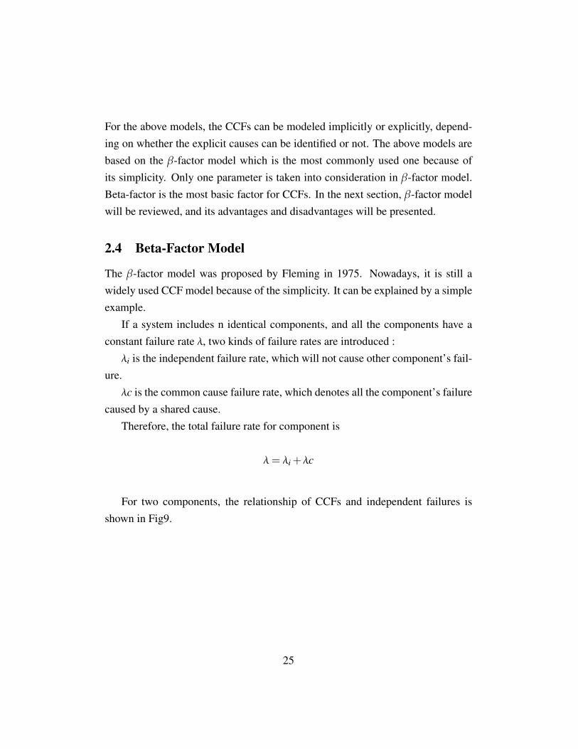
For the above models, the CCFs can be modeled implicitly or explicitly, depend-ing on whether the explicit causes can be identified or not. The above models arebased on the β-factor model which is the most commonly used one because ofits simplicity. Only one parameter is taken into consideration in β-factor model.Beta-factor is the most basic factor for CCFs. In the next section, β-factor modelwill be reviewed, and its advantages and disadvantages will be presented.
2.4 Beta-Factor Model
The β-factor model was proposed by Fleming in 1975. Nowadays, it is still awidely used CCF model because of the simplicity. It can be explained by a simpleexample.
If a system includes n identical components, and all the components have aconstant failure rate λ, two kinds of failure rates are introduced :λi is the independent failure rate, which will not cause other component’s fail-
ure.λc is the common cause failure rate, which denotes all the component’s failure
caused by a shared cause.Therefore, the total failure rate for component is
λ= λi +λc
For two components, the relationship of CCFs and independent failures isshown in Fig9.
25
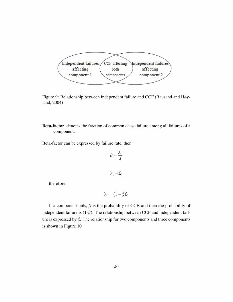
Figure 9: Relationship between independent failure and CCF (Rausand and Høy-land, 2004)
Beta-factor denotes the fraction of common cause failure among all failures of acomponent.
Beta-factor can be expressed by failure rate, then
β=λc
λ
λc =βλ
therefore,
λi = (1−β)λ
If a component fails, β is the probability of CCF, and then the probability ofindependent failure is (1-β). The relationship between CCF and independent fail-ure is expressed by β. The relationship for two components and three componentsis shown in Figure 10
26

Figure 10: β-factor relationship between components
Beta-factor model can be considered as a shock model where shocks occurrandomly according to a homogeneous Poisson process with rate λc. (Rausand,2011) Every time the shock occurs, all the channels of the system fail regardlessof the status of the channel.
Advantages of beta-factor model:
• It is simple.
• Only one parameter β need to be estimated when the data are available.
• It is easy and widely used. Some standards recommend this β-factor modelto assess the reliability of SIS.
• Many models are developed based on β-factor model, such as C-factor mod-el, multiple Beta-Factor model, Multiple Greek Letter model and so on.
• Many checklist methods are proposed to determine plant specific β-factor,such as IEC 61508-6 checklist and IEC 62061checklist.
Disadvantages of beta-factor model:
• It is simple for simple parallel systems, but it is not used for high redundancysystems.
27

• λi = (1−β)λ and some database record historical total failure rate λ whichare constant like OREDA; therefore, λi will be different when the plantspecific β factor changes. Therefore, this equation: λi = (1− β)λ is notright.
• It is not reward for different levels of redundancy.
• The traditional probability of the possible multiplicities of failure rates are(Rausand, 2011):
f1,n = 1−β
fk,n = 0
fn,n = β
Therefore, for β-factor model, intermediate values of the multiplicity of the failureevent are not possible when a failure occurs. It is either 1 or n.
• The β-factor is used for identical components with the same constant fail-ure rate λ. It is difficult for nonidentical components to estimate β-factor.Sometimes, the following approach could be used to define β-factor by ge-ometric average of the failure rate, but it is not commonly used.
λc = β*
(n
∏i=1
)1/n
For now, it is impossible to avoid β-factor; therefore, determining and reducingβ-factor is the priority to reduce CCFs. IEC 61508 is the basic standard for manykinds of industries, and it proposes a quantitative method which is a checklist todetermine β-factor. Besides, systems can operate in two demand modes which are
28

low-demand and high-demand mode. Therefore, in section 4, checklists used forlow-demand and high-demand mode systems will be presented separately, and acomparison is made. Some industries require very high reliability for SIS, such asnuclear power industry. Hence, a method (UPM) which is used for high reliabilitysystem will be presented.
29


3 Determination of Beta-Factors for SIS
There are many models existing for modeling CCFs. The most simple model isβ-factor model, because only one parameter is estimated. The β-factor maybeestimated by the use of the following methods(Lundteigen, 2010):
• Expert judgments
• Checklists
• Estimation models
• Using historical data
In this part, two IEC checklists and a estimation model will be introduced. Thetwo checklists are IEC 61508-6 checklist and IEC 62061 checklist. The estimationmodel is unified partial model.
3.1 IEC 61508 Checklist
3.1.1 Introduction
For SISs, three parts are included: the sensors, the logic subsystem and the fi-nal elements. The β-factor for these three parts are different; therefore, β-factorshould be calculated or estimated separately.
In this checklist, the following eight defenses are used. Furthermore, and 37measures are developed for these eight defenses. For the complete checklist, seethe standard IEC 61508-6 (2010), table D1.
• Separation/segregation
• Diversity/redundancy
• Complexity/design/application/maturity/experience
• Assessment/analysis and feedback of data
31

• Procedures/human interface
• Competence/training/safety culture
• Environmental control
• Environmental testing
This is a comprehensive checklist, 37 questions need to be answered based on theengineering judgment. The questions will be evaluated in the next section.
In the checklist method, the influence of extensive diagnostic tests is takeninto consideration for β-factor estimation. The overall CCF rate is divided intodangerous detected (DD) failure rate and dangerous undetected (DU) failure rate.DU failures cannot not be influenced by diagnostic tests. Therefore, the overall βis equal to βDU . Non-simultaneous CCFs may be detected by diagnostic test, soCCF rate can be reduced. Then, the overall β can be reduced. The overall failurerate is given by
λDβ =λDUβ+λDDβD
where
• λD is the dangerous failure rate of a single unit.
• β is the overall common cause failure factor which is also undetected failurefactor, without take diagnostic test into consideration.
• λDU is the dangerous undetected failure rate of a single unit.
• λDD is the dangerous detected failure rate of a single unit.
• βD is the CCF factor for dangerous detected failures which is taken diag-nostic test into consideration.
32

Two sets of values X and Y are used to estimate β-factor. X means that the di-agnostic test improves the effectiveness of the items. While Y means that thereis no influence from diagnostic test. For each question or measure in the table, ifthe answer is a yes, then the corresponding scores of the X and Y are obtained.And the ratio of X and Y represents the extent to which the measure’s contributionagainst CCFs can be improved by diagnostic test (IEC 61508, 2010).
In the table,
• XLS means the improved question value by diagnostic test for logic solver.
• YLS means the value that is not influence by diagnostic test for logic solver.
• XSF means the improved defense value by diagnostic test for sensors or finalelements.
• YSF means the value that is not influence by diagnostic test for sensors orfinal elements.
All the measures or the questions should be estimated and then the value for theelements can be found. After that, sums the columns XLS, YLS, XSF , YSF arecalculated respectively. The value Z can be yield using the Table 9 for logic sub-system and Table 10 for sensors and final elements. Factor Z stands for diagnostictest which is determined by the factor diagnostic coverage and diagnostic test in-terval.
Then, S can be calculated by using the following equations:
S = ∑Xi +∑Yi
which is to obtain the β int value for undetected failures, and
SD = ∑Xi(Z +1)+∑Yi
which is used to get the value of βDint for detected failures.
33
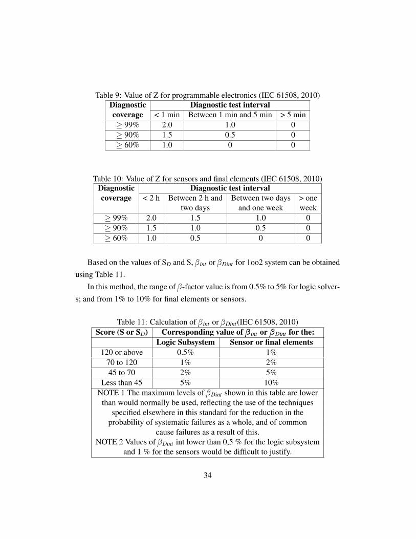
Table 9: Value of Z for programmable electronics (IEC 61508, 2010)Diagnostic Diagnostic test intervalcoverage < 1 min Between 1 min and 5 min > 5 min≥ 99% 2.0 1.0 0≥ 90% 1.5 0.5 0≥ 60% 1.0 0 0
Table 10: Value of Z for sensors and final elements (IEC 61508, 2010)Diagnostic Diagnostic test intervalcoverage < 2 h Between 2 h and Between two days > one
two days and one week week≥ 99% 2.0 1.5 1.0 0≥ 90% 1.5 1.0 0.5 0≥ 60% 1.0 0.5 0 0
Based on the values of SD and S, β int or βDint for 1oo2 system can be obtainedusing Table 11.
In this method, the range of β-factor value is from 0.5% to 5% for logic solver-s; and from 1% to 10% for final elements or sensors.
Table 11: Calculation of β int or βDint(IEC 61508, 2010)Score (S or SD) Corresponding value of β int or βDint for the:
Logic Subsystem Sensor or final elements120 or above 0.5% 1%
70 to 120 1% 2%45 to 70 2% 5%
Less than 45 5% 10%NOTE 1 The maximum levels of βDint shown in this table are lower
than would normally be used, reflecting the use of the techniquesspecified elsewhere in this standard for the reduction in the
probability of systematic failures as a whole, and of commoncause failures as a result of this.
NOTE 2 Values of βDint int lower than 0,5 % for the logic subsystemand 1 % for the sensors would be difficult to justify.
34
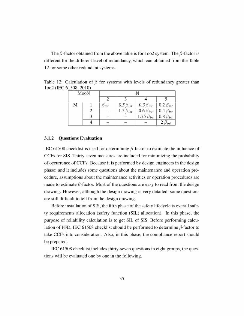
The β-factor obtained from the above table is for 1oo2 system. The β-factor isdifferent for the different level of redundancy, which can obtained from the Table12 for some other redundant systems.
Table 12: Calculation of β for systems with levels of redundancy greater than1oo2 (IEC 61508, 2010)
MooN N2 3 4 5
M 1 β int 0.5 β int 0.3 β int 0.2 β int2 – 1.5 β int 0.6 β int 0.4 β int3 – – 1.75 β int 0.8 β int4 – – – 2 β int
3.1.2 Questions Evaluation
IEC 61508 checklist is used for determining β-factor to estimate the influence ofCCFs for SIS. Thirty seven measures are included for minimizing the probabilityof occurrence of CCFs. Because it is performed by design engineers in the designphase; and it includes some questions about the maintenance and operation pro-cedure, assumptions about the maintenance activities or operation procedures aremade to estimate β-factor. Most of the questions are easy to read from the designdrawing. However, although the design drawing is very detailed, some questionsare still difficult to tell from the design drawing.
Before installation of SIS, the fifth phase of the safety lifecycle is overall safe-ty requirements allocation (safety function (SIL) allocation). In this phase, thepurpose of reliability calculation is to get SIL of SIS. Before performing calcu-lation of PFD, IEC 61508 checklist should be performed to determine β-factor totake CCFs into consideration. Also, in this phase, the compliance report shouldbe prepared.
IEC 61508 checklist includes thirty-seven questions in eight groups, the ques-tions will be evaluated one by one in the following.
35

Separation/segregation For separation/segregation, this is about the design ofthe system. If the engineers understand the design very well, there will be easy toevaluate and get the correct scores.
• Q1: Are all signal cables for the channels routed separately at all positions?
It may take sometime for engineers to check the architecture of signal cables.This is a good question for determining β-factor because if all signal cables donot routed separately, then CCFs will be caused by a shock or an accident easily.It is safer to locate signal cables separately to reduce the probability of CCFs.
• Q2: Are the logic subsystem channels on separate printed-circuit boards?
If the logic subsystem channels are on separate printed-circuit boards, the proba-bility of occurring CCFs will be reduced when there is a physical damage on oneprinted-circuit board, such as humidity, pressure, shock and so on. Although it isnot the same thing with Q1, it is not necessary to list Q1, Q2 separately.
• Q3: Are the logic subsystems physically separated in an effective manner?For example, in separate cabinets.
For this question, the engineers need to get familiar with the design principle andthe function of the design. Effective manner means logic subsystems physicallyseparated and they are independent with each other. If the logic subsystems arephysically separated in an effective manner, the cascading failure do not exist.Therefore, there is no CCFs caused by cascading failure. The overall probabilityof CCFs will be reduced.
• Q4: If the sensors/final elements have dedicated control electronics, is theelectronics for each channel on separate printed-circuit boards?
When the electronics for each channel on separate printed-circuit boards, the prob-ability of the failures caused by a common reason is very low unless it is designor technical defect.
36

• Q5: If the sensors/final elements have dedicated control electronics, is theelectronics for each channel indoors and in separate cabinets?
This question is familiar with the above question. If the electronics for each chan-nel indoors, the probability of CCFs caused by whether such as raining or lighten-ing is very low. And if the electronics located in separate cabinets, some kinds ofCCFs could be avoided or the probability will be very low, like physical damageand human errors. This question cannot be answered based on the design draw-ing. Also, since the system has not been installed, whether the electronics foreach channel indoors or not cannot be told from the design drawing. To answerthis question, some assumptions should be made.
In “separation/segregation” part, it is mainly about physical separation of thecables or elements. The location of the elements is very important, because locat-ing in different places reduce the probability of CCFs efficiently due to accidents,damages or human errors.
Diversity/redundancy
• Q6: Do the channels employ different electrical technologies; for example,one electronic or programmable electronic and the other relay?
If the answer of this question is a “yes”, then the probability of CCFs caused bytechnology defects or design error will be reduced. It is not difficult to read itfrom the design drawing.
• Q7: Do the channels employ different electronic technologies; for example,one electronic, the other programmable electronic?
This question is similar with the above question. If the channels employ differentelectronic technologies, the probability of CCFs, due to technology defects, willbe much lower than using the same technology. It can be merged with Q6. Thequestion should be “Do the channels employ different technologies?” As long asthe technologies are different, the CCFs caused by technology defect can be avoid.
37

• Q8: Do the devices employ different physical principles for the sensingelements; for example, pressure and temperature, vane anemometer andDoppler transducer, etc?
This question can be answered by reviewing the design drawing if it is in detail. Ifphysical principles are different, then the probability of CCFs caused by a sharedcause like pressure or temperature can be reduced.
• Q9: Do the devices employ different electrical principles/designs for exam-ple, digital and analogue, different manufacturer (not re-badged) or differ-ent technology?
When the devices employ different electrical principles or designs, the systemwill not fail because of the manufacturer’s error or technical/design deficiency.Therefore, different electrical principles reduce the probability of CCFs whichcaused by technology or design defect.
• Q10: Is low diversity used, for example hardware diagnostic tests using thesame technology?
Diversity means different means of performing a required function. (IEC 61508,2010)
If the system use the low diversity, the probability of CCFs will be higher thanhigh diversity due to technical defects.
• Q11: Is medium diversity used, for example hardware diagnostic tests usingdifferent technology?
About the medium diversity, using different technology will not easily cause CCFsdue to a specific technology’s fault. In my opinion, this question could be mergedwith Q10 because it is about the level of diversity. The best way to mentiondiversity is that what is the level of diversity used?. Then based on the expertjudgment to get the score from 0-10. For example, after the analysis of the system,the expert assesses the level of the diversity. The higher the diversity, the higherthe score can be obtained.
38

• Q12: Were the channels designed by different designers with no communi-cation between them during the design activities?
For this question, regarding to CCFs, when the channels designed by differentdesigners with no communication, then the probability of the CCFs caused bythe same design defects is extremely low or there is no CCFs. Besides, the anti-pressure or humidity of the channels will also be different, which reduces theprobability of CCFs caused by environment factor or external pressure efficiently.
• Q13: Are separate test methods and people used for each channel duringcommissioning?
To answer this question, it is based on the assumptions made in design phase be-cause the system has not installed. Also, relevant documents should be reviewed,which is another time-consuming work. To consider CCFs, if the same test meth-ods and people are used, and the method is not perfect for that channel or thepeople have the same habits, CCFs are easily introduced.
• Q14: Is maintenance on each channel carried out by different people atdifferent times?
This is also based on the assumptions in design phase. This question is abouthuman factor. The purpose of this question is that different people and differenttime perform maintenance to make sure CCFs are not caused by human mistakeor same technology error.
Complexity/design/application/maturity/experience
• Q15: Does cross-connection between channels preclude the exchange ofany information other than that used for diagnostic testing or voting purpos-es?
This question should be answered by on the real scenario.
39

• Q16: Is the design based on techniques used in equipment that has beenused successfully in the field for > 5 years?
If the design based on techniques used in equipment successfully more than 5years, the record of safety is good. Hence the probability of CCFs will be verylow.
• Q17: Is there more than 5 years experience with the same hardware used insimilar environments?
This is a similar question with the above one. If the same hardware is used formore than 5 years in similar environments, the technology is mature and the prob-ability of CCFs caused by technology defects will be extremely low.
• Q18: Is the system simple, for example no more than 10 inputs or outputsper channel?
There is no definite relation between the simplicity of the system and CCFs, butcompared with the different technologies being used, the probability of CCFscaused by the complexity of the system is much lower.
• Q19: Are inputs and outputs protected from potential levels of over-voltageand over-current?
For this question, it is just necessary to check the design map. If inputs and outputsprotection exist, the probability of occurrence of CCFs caused by over-voltage orover-current is very low.
• Q20: Are all devices/components conservatively rated (for example, by afactor of 2 or more)?
This is a ambiguous question for engineers to answer, which is even more difficultfor design engineers. If the answer is a “yes”, it means all devices/componentsrated in a safer way. The score will be get. The overall score will be higher, andhence the value of β-factor will be lower.
40
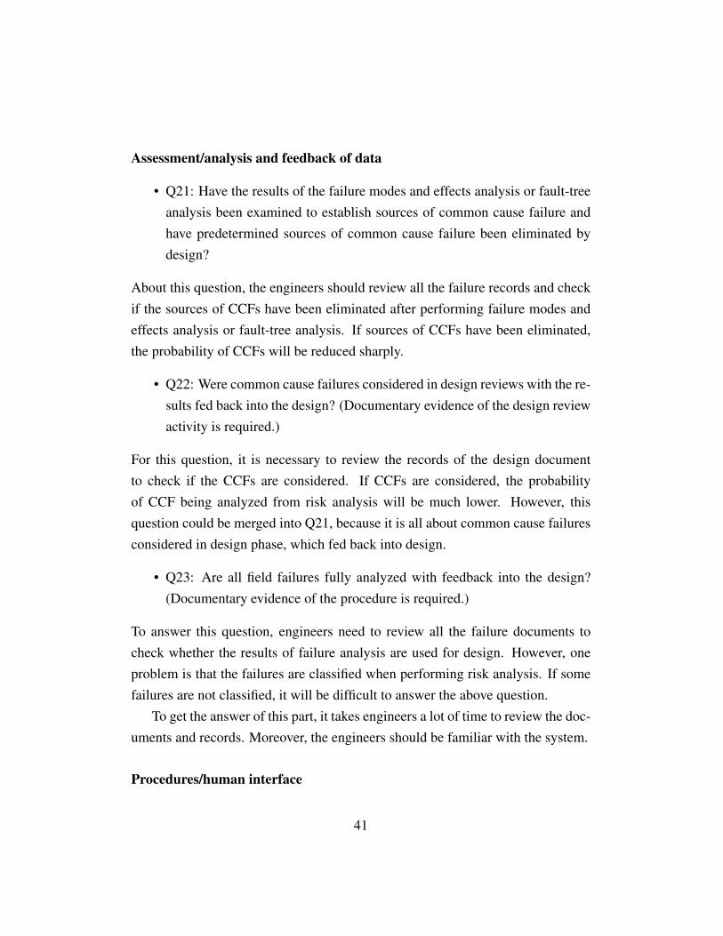
Assessment/analysis and feedback of data
• Q21: Have the results of the failure modes and effects analysis or fault-treeanalysis been examined to establish sources of common cause failure andhave predetermined sources of common cause failure been eliminated bydesign?
About this question, the engineers should review all the failure records and checkif the sources of CCFs have been eliminated after performing failure modes andeffects analysis or fault-tree analysis. If sources of CCFs have been eliminated,the probability of CCFs will be reduced sharply.
• Q22: Were common cause failures considered in design reviews with the re-sults fed back into the design? (Documentary evidence of the design reviewactivity is required.)
For this question, it is necessary to review the records of the design documentto check if the CCFs are considered. If CCFs are considered, the probabilityof CCF being analyzed from risk analysis will be much lower. However, thisquestion could be merged into Q21, because it is all about common cause failuresconsidered in design phase, which fed back into design.
• Q23: Are all field failures fully analyzed with feedback into the design?(Documentary evidence of the procedure is required.)
To answer this question, engineers need to review all the failure documents tocheck whether the results of failure analysis are used for design. However, oneproblem is that the failures are classified when performing risk analysis. If somefailures are not classified, it will be difficult to answer the above question.
To get the answer of this part, it takes engineers a lot of time to review the doc-uments and records. Moreover, the engineers should be familiar with the system.
Procedures/human interface
41

• Q24: Is there a written system of work to ensure that all component failures(or degradations) are detected, the root causes established and other similaritems inspected for similar potential causes of failure?
This is also a complicated work to do. Many kinds of documents need to bereviewed. However, if the written system of the work exists, measures will bedeveloped to reduce the probability of CCFs and other kinds of failures.
• Q25: Are procedures in place to ensure that: maintenance (including adjust-ment or calibration) of any part of the independent channels is staggered,and, in addition to the manual checks carried out following maintenance,the diagnostic tests are allowed to run satisfactorily between the completionof maintenance on one channel and the start of maintenance on another?
Because the question is answered in design phase, the procedures for maintenanceactivities cannot be read from the design drawing. It is also based on the assump-tions made in design phase.
• Q26: Do the documented maintenance procedures specify that all parts ofredundant systems (for example, cables, etc.) intended to be independent ofeach other, are not to be relocated?
If all parts of redundant systems are independent to each other, there is no cas-cading failures. Therefore, the probability of CCFs caused by other componentfailure is low. Under this condition, the probability of occurring CCFs is muchlower than the condition of dependent components.
• Q27: Is all maintenance of printed-circuit boards, etc. carried out off-site ata qualified repair center and have all the repaired items gone through a fullpre-installation testing?
If all repaired items gone through a full pre-installation testing, not functioningspare parts can be avoided. Therefore, the probability of CCFs caused by the newitems can be reduced.
42

• Q28: Does the system have low diagnostic coverage (60 % to 90 %) andreport failures to the level of a field-replaceable module?
• Q29: Does the system have medium diagnostics coverage (90 % to 99 %)and report failures to the level of a field-replaceable module?
• Q30: Does the system have high diagnostics coverage (>99 %) and reportfailures to the level of a field-replaceable module?
Question 28 to 30 are about the diagnostic coverage. The higher the diagnosticscoverage is, the more the failures are detected and avoided. Therefore, the lessCCFs arise. These three questions are not necessary to be listed one by one, andcan be merged into one question and three levels of score.
• Q31: Do the system diagnostic tests report failures to the level of a field-replaceable module?
For low-demand systems, this is a very important aspect to check. The system isdoing diagnostic test all the time. If the failure of a component is revealed whenthe function of this component is not on demand, and the failure is reported to thelevel of a field-replaceable module, the component could be replaced, and CCFscaused by this component is avoided. However, the CCFs, under this condition,cannot be avoided because the failure occurs when the function of the componentis on demand. Also, if the system diagnostic tests report failures to the levelof a field-replaceable module, the probability of occurring CCFs will be low. Ifthe system diagnositc tests do not report failures, the probability of CCFs willincrease.
Competence/training/safety culture
• Q32: Have designers been trained (with training documentation) to under-stand the causes and consequences of common cause failures?
43

It is a company’s culture. If the designers have been trained, they will understandthe causes of CCFs, so pay attention to it and avoid it. Then, the probability ofoccurring CCFs could be reduced.
• Q33: Have maintainers been trained (with training documentation) to un-derstand the causes and consequences of common cause failures?
This is a similar question with Q32. If maintainers have been trained, causes willbe easily found out, maintained and checked, so the probability of CCFs will bevery low.
Environmental control
• Q34: Is personnel access limited (for example locked cabinets, inaccessibleposition)?
It is in the design phase to perform this checklist, the system has not installed,so there is no way to check it. To answer this question, it has to be based onthe assumptions made in design phase. If the access is not limited, then non-professional staff or irrelevant staff may enter into this area and lead to CCFs.
• Q35: Is the system likely to operate always within the range of tempera-ture, humidity, corrosion, dust, vibration, etc., over which it has been tested,without the use of external environmental control?
If the system is likely to operate within the range of temperature, humidity, cor-rosion, dust, vibration, etc., over which it has been tested, then the probabilityof CCFs caused by temperature, humidity, corrosion, dust, vibration, etc will bereduced.
• Q36: Are all signal and power cables separate at all positions?
This is a time consuming question. Engineers should take much time to checkand find out the result. However, if all signal and power cables separate at allpositions, CCFs caused by a shock or external stress will not happen.
44

Environmental testing
• Q37: Has the system been tested for immunity to all relevant environmentalinfluences (for example EMC, temperature, vibration, shock, humidity) toan appropriate level as specified in recognized standards?
To answer this question, what the engineers need to do is to review the documentsto check if the system has been tested under all relevant environmental condition.To check the environmental control questions, environmental testing should bedone first.
3.1.3 Discussions
After the evaluation of this checklist, I think the measures related to human er-ror/factor are not enough. More questions about human factor should be devel-oped and should be a big part of this checklist because human factor influencesthe CCFs significantly. For example, over-time working distract engineers, thusleading to shutdown of the system. Also, different people may treat problemsdifferently. Besides, questions included in one factor are similar. It makes thequestions repetitive. Therefore, I think this checklist is not perfect, and I willpropose a question list in subsection 4.1.5.
3.1.4 Advantages and Disadvantages
The checklist is performed by a group of integrity engineers who cooperate withthe other engineers in a company. It is mainly used in process industry. It is usedto determine plant specific β-factor of CCFs. It is widely used for low-demandsystem.
The advantages of the IEC 61508-6 checklist are listed below:
• The specific β-factor value can be obtained.
• Many kinds of factors are considered.
45

• The influence of diagnostic test is considered.
• 37 measures are proposed to reduce the probability of common cause fail-ure.
Although the advantages of IEC 61508-6 checklist, some disadvantages of thischecklist cannot be ignored.
The disadvantages of IEC 61508-6 checklist are
• Some questions are difficult to answer because they are based on practice.
• It takes much time to review all the relevant documents.
• Human factors questions are not considered enough.
• It requires design engineers or specific engineers to perform this checklist.
3.1.5 Proposed Checklist
I think some of the questions are not necessary because some of them are similarand can be merged. Also, in my opinion, the scoring system of this checklist is notperfect because there is no definite answer for some questions. The answer “yes”or “no” cannot describe the condition of the system. In addition, because there isno available database to support this checklist and the procedure of calculation,I propose that the score of each value should have a range from one to ten. Forexample, if the system uses very high diversity, the score could be nine or ten.If the system uses low diversity, the score could be 2 or 3 based on the expertjudgment. In my proposed checklist, the same eight factors are taken into account.
Separation/segregationWhat degree of the overall physical separation of the systems (including signal
cables, main elements of the system) are used?Diversity/redundancyWhat degree the diversity the systems are used?
46

What degree the test methods (different test methods are used for each chan-nel) are used?
What degree the technologies the system are used?Complexity/design/application/maturity/experienceWhat degree the maturity of the design technology is?Is the design has been used in a similar environment for more than 5 years
successfully (experience)?What degree of the inputs and the outputs are protected (like over-voltage,
over-current protection)?Assessment/analysis and feedback of dataWhat degree of the failures data (obtained from risk analysis in design phase
like FMECA) feed back into design and be used to eliminate the sources of CCFs?Procedure/human interfaceWhat the degree of the training to understand CCFs (only trained before work
once, or regular training every week, or a written procedure that tell staff how totreat and recognize CCFs) is?
What degree the failures revealed by the diagnostic coverage being reportedto the level of a field-replaceable module?
How people trained about how to deal with different failures?Environmental controlWhat extent the access limited is? (only relevant engineer, or all staff, or
inaccessible?)Environmental controlIs the system has been tested in all relevant environmental condition (like tem-
perature, humidity, vibration, shock, corrosion, dust etc. ) and meet the standardrequirement?
The reason why above questions are listed is that these questions cover alleight factors. The checklist I propose is much simpler than the one from IEC61508, but it covers most aspects of the eight factors. Take the separation factoras an example, it is about physical separation, so one question about the degree
47

of the separation of the system is enough. Based on the expert judgment of thesystem, the corresponding score is obtained. If the elements or cables separatevery well, the score is 10. If there is almost no separation of the cables or elements,then the score could be 0. This checklist should be performed by the professionalengineers with experience.
3.2 IEC 62061 Checklist
3.2.1 Introduction
Standard IEC 62061 is Safety of machinery — Functional safety of safety-related
electrical, electronic and programmable electronic control systems. Be similar toIEC 61508-6 checklist, IEC 62061also determines β-factor by expert judgment,answering a list of questions. Besides, this is a qualitative based method. Thedifference from IEC 61508 is that IEC 62061 checklist is used for machinery fieldwhich is for high demand operation mode.
IEC 62061 checklist is less complicate than IEC 61508-6 checklist. Only 14items are included in this checklist. The measures are shown in Table 13:
48

Table 13: IEC 62061 checklist of determine CCF (IEC 62061, 2005)Item Reference ScoreSeparation/segregationAre SRECS signal cables for the individual channels
1a 5routed separately from other channels at all positionsor sufficiently shielded?Where information encoding/decoding is used, is it
1b 10sufficient for the detection of signal transmissionerrors?Are SRECS signal and electrical energy power
2 5cables separate at all positions or sufficientlyshielded?If subsystem elements can contribute to a CCF,
3 5are they provided as physically separatedevices in their local enclosures?Diversity/redundancyDoes the subsystem employ different electrical
4 8technologies, for example, one electronic orprogrammable electronic and the other anelectromechanical relay?Does the subsystem employ elements that use
5 10different physical principles(e.g. sensing elementsat a guard door that use mechanical and magneticsensing techniques)?Does the subsystem employ elements with temporal
6 10differences in functional operation and/or failuremodes?Do the subsystem elements have a diagnostic test
7 10interval of ≤1 min?Complexity/design/applicationIs cross-connection between channels of the
8 2subsystem prevented with the exception of thatused for diagnostic testing purposes?
49

Item Reference ScoreAssessment/analysisHave the results of the failure modes and effects
9 9analysis been examined to establish sources ofcommon cause failure and have predeterminedsources of common cause failure been eliminatedby design?Are field failures analyzed with feedback into the
10 9design?Competence/trainingDo subsystem designers understand the causes and
11 4consequences of common cause failures?Environmental controlAre the subsystem elements likely to operate always
12 9within the range of temperature, humidity, corrosion,dust, vibration, etc. over which it has been tested,without the use of external environmental control?Is the subsystem immune to adverse influences from
13 9electromagnetic interference up to and including thelimits specified in Annex E?NOTE: An alternative item (e.g. references 1a and 1b) is given in Table F.1where it is intended that a claim can be made for a contribution towardsavoidance of CCF from only the most relevant item.
Compared with IEC 61508-6 checklist, IEC 62061 evaluates six defenses in-stead of eight which are:
• Separation/segregation
• Diversity/redundancy
• Complexity/design/application
• Assessment/analysis
• Competence/training
• Environmental control
50

Also, the scoring system is used. If the answer of the question is a “Yes”, thecorresponding score can get. After answering all the questions in figure, it is easyto sum up the scores. Finally, use the overall score to find the correspondingβ-factor value by table 14.
Table 14: Estimation of CCF (β-factor) (IEC 62061, 2005)Overall score Common cause failure factor (β)
< 35 10% (0.1)35-66 5% (0.05)65-85 2% (0.02)
85-100 1% (0.01)
If the total score is 70 based on the checklist, then the β-factor is 2% based onthe above table.
Compared with IEC 61508-6 checklist, this one is much easier and simpler.
3.2.2 Discussions
This checklist method is a very simple qualitative based approach to estimateCCF (β-factor). It used for machinery industry which is a high-demand operationsystem. Compared with the IEC 61508-6 checklist, one of the advantages of thisis that it is much simpler and only 14 questions to check. However, to performthis checklist, the engineers should be professional design engineers. Besides, alot of documents need to be reviewed, which takes much time.
3.3 Comparison of IEC 61508 and IEC 62061 Checklists
3.3.1 Similarity of Two Checklists
Both checklists are used to determine plant specific β-factor of common causefailures for SIS. These two IEC checklists provide series of measures to defenseagainst CCFs, which is evaluated by expert estimation. Both checklist methodsuse scoring system and are used for design phase.
51
3.3.2 Main Differences Between Two Checklists
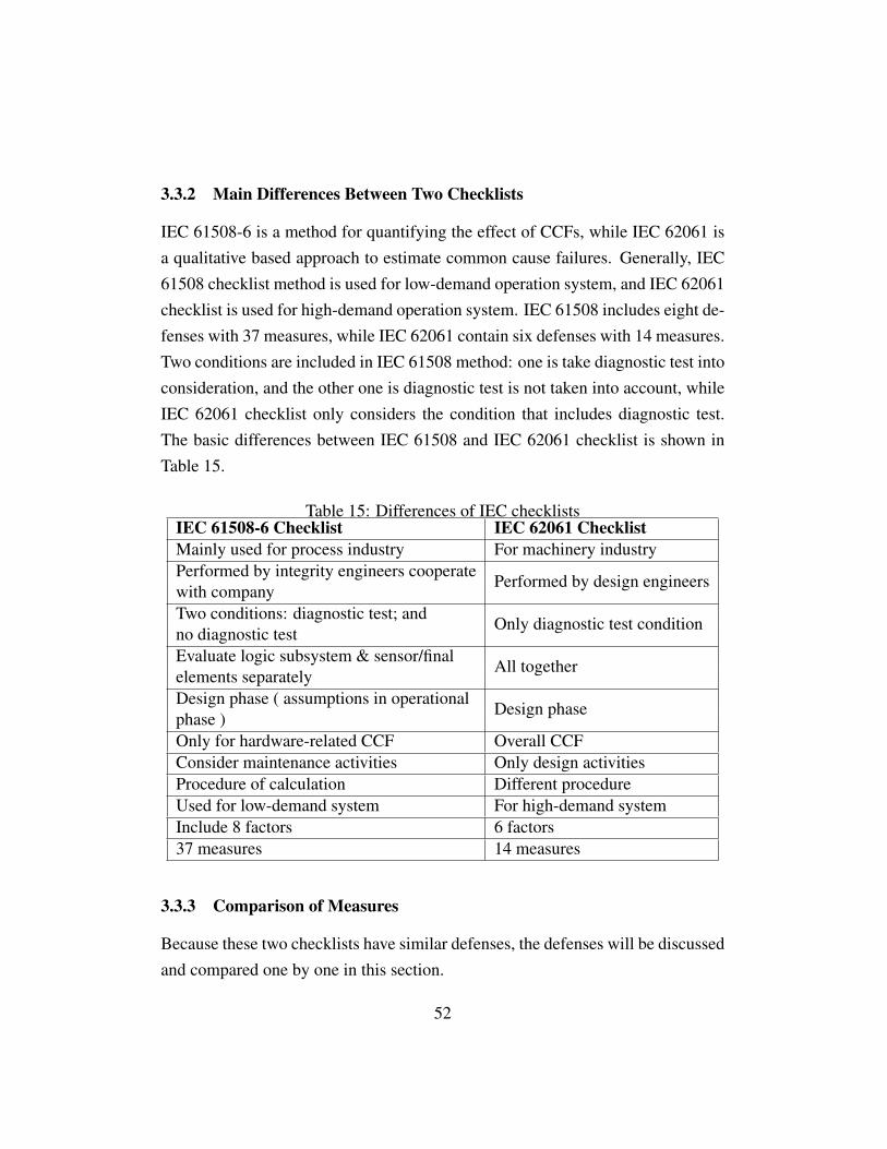
IEC 61508-6 is a method for quantifying the effect of CCFs, while IEC 62061 isa qualitative based approach to estimate common cause failures. Generally, IEC61508 checklist method is used for low-demand operation system, and IEC 62061checklist is used for high-demand operation system. IEC 61508 includes eight de-fenses with 37 measures, while IEC 62061 contain six defenses with 14 measures.Two conditions are included in IEC 61508 method: one is take diagnostic test intoconsideration, and the other one is diagnostic test is not taken into account, whileIEC 62061 checklist only considers the condition that includes diagnostic test.The basic differences between IEC 61508 and IEC 62061 checklist is shown inTable 15.
Table 15: Differences of IEC checklistsIEC 61508-6 Checklist IEC 62061 ChecklistMainly used for process industry For machinery industryPerformed by integrity engineers cooperate
Performed by design engineerswith companyTwo conditions: diagnostic test; and
Only diagnostic test conditionno diagnostic testEvaluate logic subsystem & sensor/final
All togetherelements separatelyDesign phase ( assumptions in operational
Design phasephase )Only for hardware-related CCF Overall CCFConsider maintenance activities Only design activitiesProcedure of calculation Different procedureUsed for low-demand system For high-demand systemInclude 8 factors 6 factors37 measures 14 measures
3.3.3 Comparison of Measures
Because these two checklists have similar defenses, the defenses will be discussedand compared one by one in this section.
52

Separation/segregation Both checklists contain the factor separation, and be-cause IEC 61508 treats logic subsystems and sensors/final elements differently,the measures are differently listed. Therefore, the questions of two checklists de-veloped on separation are very alike. It is about the physical separation and signalcables separation. The only difference about separation is that IEC 61508 hasdifferent items for logic subsystem and sensors/final elements.
Diversity/redundancy IEC 61508 and IEC 62061 have two similar questions.Because IEC 61508 takes diagnostic test into consideration, it includes more ques-tions for diagnostic tests. Besides, IEC 61508 is also used for operation phase,and more questions about maintenance and procedure problems included. TheIEC 62061 only have one question about diagnostic test interval, and it is Do the
subsystem elements have a diagnostic test interval of ≤ 1 min?
Complexity/design/application The title about this sub-factor is for IEC 62061.This factor for IEC 61508 is complexity/design/application/maturity/experience.IEC 61508 is used for low-demand operation system. And if the experience isnot enough or the technology is immature, it may cause failures very often or in-fluence the operation of the system; therefore, it is very important for IEC 61508checklist. Also the frequency of low-demand is less than one time per year. Thematurity of the technology maybe need more than five years for low-demand sys-tem. While for high-demand system, if the technology or the experience is usedmore than 1 year, then the technology is mature; therefore the maturity of tech-nology is not so meaningful for high-demand system (IEC 62061) as long as itexperiences the experiment and it has been put in use for one year. In addition,one question for IEC 61508 is that Is the system simple, for example no morethan 10 inputs or outputs per channel?, which is not so relevant with commoncause failure, so it could be ignored.
Assessment/analysis and feedback of data The title of this sub-factor is forIEC 61508, while there is no feedback of data for IEC 62061. Three questions for
53

IEC 61508 and two for IEC 62061. The two questions in IEC 62061 are almostthe same with two of them in IEC 61508. IEC 61508 has one question more thanIEC 62061 which is Were common cause failures considered in design reviewswith the results fed back into the design? As discussed in questions evaluation,this one could be emerged to the first question of this factor.
Procedures/human interface This title is for IEC 61508, while this factor doesnot not exist in IEC 62061 because IEC 62061 is only used for facilitating design.Therefore, this sub-factor is not suitable for IEC 62061 checklist.
Competence/training/safety culture This title is for IEC 61508 while IEC 62061does not include safety culture. There are two questions for this defense in IEC61508, one is for design engineer, and one is for maintenance engineer. IEC 62061contains only one question for design engineer which is the same question withIEC 61508. Because IEC 62061 is only for design phase, maintenance activitiesor training should not be included in this factor.
Environmental control Both checklists have the same factor of this. Theyhave a same question about the subsystem likely to operate within the range oftemperature, humidity, corrosion, dust, vibration, etc. Because IEC 61508 is forlow-demand system, it also includes personnel access limitation. Also the ques-tion in IEC 61508 Are all signals and power cables separate at all positions?
should be included in factor separation.
Environmental test This factor is included in IEC 61508, not included in IEC62061.
According to the measures comparison in subsection 4.3.3 and Table 15, ifIEC 61508 is used in high-demand system, the questions under the assumptionsof operational phase will not be considered. Besides, only hardware-related CCFconsidered and it ignores other kinds of CCFs. In addition, 23 questions will beignored in high-demand system. Hence, the value of β-factor obtained from IEC
54

61508 checklist cannot be the same when the checklist is used for low-demandand high-demand systems.
55


4 Unified Partial Method
The unified partial method (UPM) was proposed by Brand (1996) and further de-veloped by Zitrou and Bedford in 2003 (Rausand, 2011). It is CCF quantificationthrough improving Partial Beta Factor method (PBF) for component level analy-sis. And it uses cut-off method structure for system level analysis. UPM is thestandard approach for UK nuclear industry determining β-factor. It is popular andwidely used in high reliability industry. The reason is popular that it can be usedwhen available data are limited.
PBF method contains 19 factors influence β-factor, while UPM method com-bines these 19 factors into the following eight underlying factors, which can coverthe all the aspects that effect the probability of common cause failure of the sys-tem. These 19 sub-factors are belong to three areas, see Table 16.
Table 16: UPM sub-factors (Wang, L.Y., 2011)Factor Sub-factor
Design
Redundancy and diversity (s1)Separation (s2)
Understanding (s3)Analysis (s4)
Operation Operator interaction(s5)Safety culture(s6)
Environment Environmental control (s7)Environmental tests(s8)
The above eight factors show the probability of all aspects that effect the com-mon cause failures of the system equipment. Each factor has five attributes (A toE) and each attribute has a corresponding weight and score. Analyzing these eightfactors is to combine the design of the system and the experienced data providedby UPM to make the analysis process much more practicable.
Brand (1996) provides a application guide to use unified partial method. It isshown in Figure 11
57

Figure 11: UPM application guide (Brand, 1996)
To perform UPM, the first step is to define the physical boundary of the system.And a pre-analysis table is produced for assessment. The second step is to choosewhich method should be used. If it is a system assessments, the Cut-off methodis selected. And Partial Beta Factor method should be selected for componentlevel assessment. The third step is to assess the sub-factors which are the defensesagainst failures. There are eight sub-factors and each factor have five criteria toassess the quality of the defense. About the criteria for sub-factors and how toassess it will be described in next section. Based on the expert judgment, thecorresponding scores are obtained by Table 17.
58
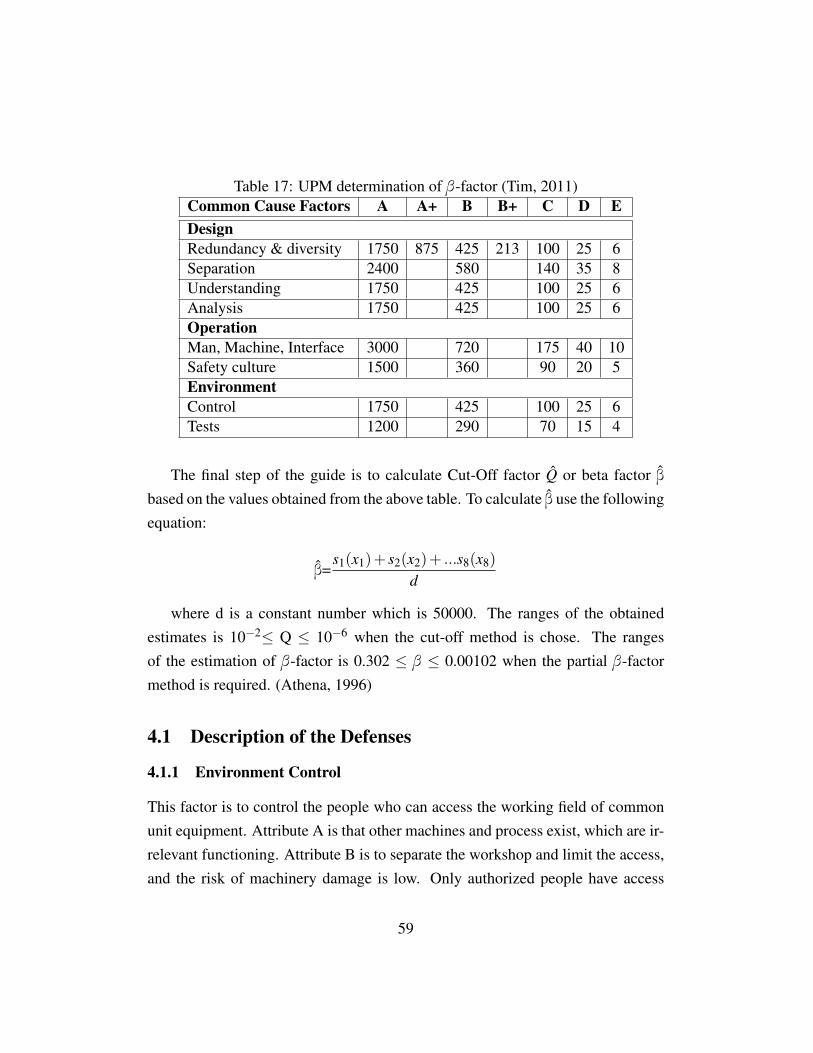
Table 17: UPM determination of β-factor (Tim, 2011)Common Cause Factors A A+ B B+ C D EDesignRedundancy & diversity 1750 875 425 213 100 25 6Separation 2400 580 140 35 8Understanding 1750 425 100 25 6Analysis 1750 425 100 25 6OperationMan, Machine, Interface 3000 720 175 40 10Safety culture 1500 360 90 20 5EnvironmentControl 1750 425 100 25 6Tests 1200 290 70 15 4
The final step of the guide is to calculate Cut-Off factor Q̂ or beta factor β̂based on the values obtained from the above table. To calculate β̂ use the followingequation:
β̂=s1(x1)+ s2(x2)+ ...s8(x8)
d
where d is a constant number which is 50000. The ranges of the obtainedestimates is 10−2≤ Q ≤ 10−6 when the cut-off method is chose. The rangesof the estimation of β-factor is 0.302 ≤ β ≤ 0.00102 when the partial β-factormethod is required. (Athena, 1996)
4.1 Description of the Defenses
4.1.1 Environment Control
This factor is to control the people who can access the working field of commonunit equipment. Attribute A is that other machines and process exist, which are ir-relevant functioning. Attribute B is to separate the workshop and limit the access,and the risk of machinery damage is low. Only authorized people have access
59

to this area, and all the activities is relevant, so the attribute is C. Attribute D isunder the strict surveillance, and only trained persons can access the limited area.All the equipment and service depend on the designed control. Attribute E meansmuch more narrow activity scope, like the cockpit of the plane or the other controlroom.
4.1.2 Environment Test
The environment test is about the condition of the environment test of the commonequipment. Attribute A is that there is no environment test except the standardenvironment test provided by manufacture. The environment test is the conditionthat uses the sample device and requires the operation staff, which is the attributeB. Attribute C is to perform a detailed experiment on sample device to make surethe device can survive under all kinds of condition, like humidity, temperature,vibration and so on. Attribute D is to perform the experiment to use the device,operate and test in a reasonable period of time. Attribute E is to work with theexisting equipment for a period of time before put it in use.
4.1.3 Analysis
This factor reflects the analyzed system. Normally, it is the feedback of whetherthe staff have the experience of failure analysis. It also reflects whether the de-sign engineers have the full understanding of the common cause failure and themeasurements. If there is no formal safety assessment and no design experimentof the relevant common cause failure, the attribute is A. If higher level researchis performed, like FMEA, or the design engineers have the full understanding ofthe relevant failure problem, the attribute is considered as B. When the attribute isC, then reliability assessment and feedback should exist, and the engineers havethe specific knowledge of the relevant failures. Attribute D is very similar withattribute C. At the same time, having the management supports for the feedbackof the design or working evaluation. Having the reliability assessment and the
60

management support for the feedback of the design or working evaluation. Mean-while, the designers have the knowledge of the relevant failures.
4.1.4 Safety Culture
This factor reflects the training of the staff and the condition of the safety cultureof the company. If the company performs on-the-job training, then the attribute isA. If the company provides systematic and regular training, including normal andemergency operational training, it belongs to attribute B. If the company providesthe simulator training for normal operation, or dedicated staff are able to demon-strate that the safety culture is good including systematic training , the attribute isC. In addition to C, it belongs to attribute D if the company provides the simulatortraining for normal operation, or dedicated staff are able to demonstrate that thesafety culture is good including systematic emergency operation training. Whenthe simulator training for normal and the emergency operation are provided, andthe company have the clear safety policy or culture, the attribute can be consideredas E.
4.1.5 Separation
To assess this factor, it should be based on the layout of the design and the workingplace for the common cause equipment. The unified partial method treats electricequipment and machinery equipment differently. It also can be divided into 5categories. For electric equipment, if the common cause components locate inthe same cabinet, the attribute of separation should be the first category. If thecommon cause components locate in the same cabinet, but they are separated bya barrier, it is the second category. When the common cause components locatein the different cabinet, the category is the third one. However, when the commoncause components locate in the different cabinet, and there is distance betweencabinets, it is the forth category. If the common cause components locate in thedifferent room, it is the last category.
61
For machinery equipment, if the common cause components locate in the sameroom, it belongs to category one. When the common cause components locate inthe same room, but there is a physical separation between the devices, it is thesecond category. If the common cause components device locate in adjoiningroom, it is class three. When the common cause components device not locatein the adjoining room, it is the forth category. If the common cause componentsdevice locate in the different workshop, then it is the last category for machineryequipment.
4.1.6 Redundancy and Diversity
This factor reflects the redundancy and the functioning, and it also reflects thediversity of the operation. It divided into seven attributes. Attribute A means theminimum redundancy, for example 1 out of 2, 2oo3, or 3oo4 systems. The at-tribute A+ means the enhanced redundancy which is the 1oo3, 2oo4 systems andso on. Attribute B is for correspond to the extreme strong redundancy, such as1oo4, 1oo5, or 2oo5 system. Attribute B+ means the high redundancy for thesame components, for example 1 out of 8 system. Attribute C means the samecomponents have the enhanced redundancy and the diversity for functioning; Calso means the same components having the extreme high redundancy and theoperation diversity. Besides, the same components have high redundancy in thepassive system. Attribute is D when the corresponding same components have ex-tremely high redundancy like 1oo4 architecture, and the functioning are diversity.Attribute E corresponding two completely different and independent subsystem.
4.1.7 Understanding
The understanding reflects the technology maturity that the common cause com-ponents used. This unified partial method assesses this factor from four aspects:
• the running experience of the common cause components, if the experienceis more than 10a or less than 10a.
62
• the novelty of the technology that the common cause components used ifthe running of the equipment need the support of the computer software.
• the complexity of the technology that the common cause components adopt-s.
• if the adopted technology of the common cause components satisfy the de-sign requirement.
For the above four aspects, all the conditions belong to attribute A except thecondition that the system have the software. The last three aspects are consideredas “big” or “small”. Then, it is able to evaluate the attribute of this factor. Forexample, when the experience is more than 10a, and two “big”, one “small”, theattribute is C.
4.1.8 Operator Interaction
This factor reflects the complete degree of the operating procedure, and the prob-ability of operating and maintenance staff making mistakes.
4.2 Discussion
For now, UPM is the most popular and widely used method in the UK nuclearindustry for analyzing CCFs. The method is performed step by step based on thestandard guide. Compared with other models of determining β-factor, UPM hassome advantages.Advantages:
• simple model
• overall consideration of personnel experience and safety culture
• non-professional people have access to the framework
• experienced expert and non-professional staff get the same answer
63

• can be used for both component level system and system level system
• do not require much system-specific data
• have a standard guide, so easy to perform
• it is a decision making process
Disadvantages are also inevitable:
• In this method, the values are determined by expert judgment, if there isdesign and operation change, the scores have to be adjust.
• Because non-experts can perform this method, the result may not so accu-rate.
4.3 Comparison Between IEC Checklists and UPM
The three methods described in this master thesis are used to determine commoncause failure (beta-factor). IEC 61508-6 checklist is used for low-demand sys-tems, mainly for process industry, while UPM is used for high reliability industry,most commonly used for nuclear power industry. IEC checklist is performed onlyby professional engineers while UPM can be performed by both professional andnon-professional engineers. Both IEC checklists and UPM use defenses to reducethe system vulnerability to CCFs. However, IEC checklists are supplemented byseries of questions (measures) to get scores, while UPM uses genetic tables tolook for the corresponding scores. UPM provides a systematic framework whichcan be used for both system level and component level assessment. IEC checklistcan only used for single level assessment. All the three methods take human factorinto consideration, but IEC checklists only mentioned a little. In contrast, UPMconsidered enough human factor.
64
5 Summary and Recommendations for Further Work
5.1 Summary
In this master thesis, SIS is designed to meet the requirements of IEC61508 toverify if the risk reduction targets have been achieved. In order to improve thereliability of the SIS, redundancy is often introduced. However, redundancy alsoincreases the vulnerability of the system to CCFs. There is no unified definitionof CCFs, because different authors and specialists in various fields have differ-ent opinions. Therefore, a review of the definitions of CCFs has been presented.There are two kinds of causes of CCFs. One is root causes which are the basiccauses of the failures. Another one is coupling factors which are coupled withredundancy. CCFs are very important consideration in probability safety assess-ment (PSA), since they may lead to disaster accidents. As a result, CCFs haveattracted many researchers in recent years.
The most widely used method for modeling CCFs is beta-factor model. Thebrief introduction has been written in the early part of this master thesis, includingadvantages and disadvantages. Determining β-factor is an inevitable and vital partto modeling CCFs. Therefore, the main part of this master thesis is the methodsdetermining β-factor. Three methods are described: IEC 61508-6 checklist forlow-demand system, IEC 62061 checklist for high demand system, and UPM forhigh reliability industry. The advantages and disadvantages of these methods havebeen listed. Besides, the detailed comparisons between these three methods areconducted.
From my point of view, IEC checklists do not take much human factors intoconsideration. Human errors or action could affect the operation and the reliabilityof the system significantly. Therefore, more questions about human factors shouldtaken into account. For IEC 62061 checklist which is for high-demand operationsystem, human factors are especially important because wrong operation couldlead to the shutdown of the whole system. Further, it may cause the productionloss or more severe consequences. In short, IEC checklists should consider more
65

about human factor (training, working hours, etc).
5.2 Challenges
There are some difficulties occurred when people use this kinds of methods. Whenperforming the critical evaluation of the 37 questions of IEC 61508-6 checklist,it is difficult for analysts well understand how the system works and know whatkinds of documents the company should have. Besides, it requires the profes-sional engineers to assess the checklist, and they must be very familiar with thedesign architecture of the system. Therefore, it is also difficult to judge if thequestions are challenges for engineers. The only thing in this thesis is to connectthe questions to CCFs, and then find out the consequences of not including thesemeasures. However, the expriences of engineers who evlauate the checklist havesignificant influence on the result, because some of the questions need operationexperience to get the answer.
One challenge in the method of IEC 61508 is that it is not well approved.There is still dispute on this checklist among researchers and engineers. No e-nough evidence is provided that the beta-factor determined by the IEC 61508checklist reflect the real situation. Actually there is not much history data sup-porting the scoring system of both IEC 61508 and IEC 62061 checklists.
Another challenge is that there is no common CCF definition for all industries.As a result, the effectiveness of some measures in checklist methods maybe notthe same in different industries.
5.3 Recommendations for Further Work
For further work, a general definition of CCFs should be proposed that can beused in all industries. Nowadays, although it is well known that CCFs are veryimportant and it is a big threat to reliability assessment, there is no engouht studieson CCFs, and CCFs are not documented carefully. In the future, it is important todevelop a more specific and accurate model for modeling CCFs. Also, for further
66

work, collecting CCFs data from different industries and creating documents forCCFs could be done. And for IEC 61508 checklist, more questions about humanfactors should be considered and developed.
For the future work of β-factor determination, a general and more accuratemethod should be developed based on these three methods for all industries. In theoperational phase, more CCFs maybe involved, but they are not well consideredin existing checklists. Therefore, it is necessary to identify and model CCFs ofthe operational phase in determining β-factor.
67


Nomenclature
BFR Binomial Failure Rate
BP Basic Parameter
CMF Common Mode Failure
DD Dangerous Detected
DU Dangerous Undetected
FTA Fault Tree Analysis
LOPA Layer Of Protection Analysis
MBF Multiple Beta-Factor
Model Multiple Greek Letter
MTBF Mean Time Between Failure
PBF Partial Beta Factor
PFD Probability of Failure on Demand
PFH Probability of Failure per Hour
PLC Programmable Logic Controllers
PSA Probability Safety Assessment
RBD Reliability Block Diagrams
RCA Root Cause Analysis
SD Safe Detected
SIF Safety Instrumented Functions
69

SIL Safety Integrity Level
SIS Safety Instrumented Systems
SU Safe Unetected
UPM Unified Partial Method
70

References
[1] IEC 61508 (2010). Functional safety of electrical/ electronic/programmableelectronic safety-related systems. Parts 1–7. International ElectrotechnicalCommission, Geneva.
[2] BussinessDictionary, retrived from http://www.businessdictionary.com/ def-inition/reliability.html.
[3] Jin, H. (2012). Reliability of safety systems: Design to operation. Depart-ment of Production and Quality Engineering, NTNU
[4] OREDA (2002). Offshore reliability data, 4th ed. Available from: De-t Norske Veritas, NO 1322 Høvik, Norway.
[5] Smith, A. M. and Watson, I. A. (1980). Common cause failures – a dilemmain perspective. pp 127–142.
[6] Hauge, S., Lundteigen, M. A., Hokstad, P., and Håbrekke, S. (2010). Re-liability prediction method for safety instrumented systems, PDS methodhandbook. Technical Report Sintef A13503, NO-7465 Trondheim, Norway.
[7] Rausand, M. and Høyland, A. (2004). System Reliability Theory: Models,Statistical Methods, and Applications. Wiley, Hoboken, NJ, 2nd edition.
[8] Lundteigen, M. A. (2006). Hardware safety integrity (HSI) in IEC 61508/IEC 61511, Lecture slides.
[9] Wetherholt, J., (2011). Common cause failure modes. NASA Marshall SpaceFlight Center, Huntsville, Alabama, USA.
[10] Lundteigen, M. A. (2007). CCFs - definitions, models and defenses. Lectureslides.
[11] NEA (2004). International common-cause failure data exchange.(NEA/CSNI/R(2004)4). Neclear Energy Agency.
71

[12] NEA (2004b). International common-cause failure data exchange. ICDEgeneral coding guidelines. Technical report R(2004)4, Nuclear Energy A-gency, Paris.
[13] IEC 615011 (2003). IEC 61511 Standard. Functional safety - safety instru-mented systems for the process industry sector.
[14] NUREG/CR-4780 (1988). Procedures for treating common-cause failures insafety and reliability studies.
[15] NASA (2002). Probabilistic risk assessment procedures guide for nasa man-agers and practitioners. Technical report, NASA Office of Safety andMissionAssurance.,Washington DC.
[16] Rausand, M. (2011). Risk Assessment: Theory, Methods, and Applications.Wiley, Hoboken, NJ.
[17] Stamatelatos, M., Apostolakis, G., Dezfuli, H., Everline, C., Guarro, S.,Moieni, P., Mosleh, A., Paulos, T., and Youngblood, R. (2002A). Probabilis-tic risk assessment procedures guide for NASA managers and practitioner-s. Technical report, U.S. National Aeronaustics and Space Administration,Washington, DC.
[18] US DOE (1992). Root cause analysis guidance document. Technical ReportDOE-NE-STD-1004-92, U.S. Department of Energy, Office of Nuclear En-ergy, Washington, DC.
[19] Miller, A. G., Kaufer, B., and Carlson, L. (2000). Activities on componentreliability under the OECD Nuclear Energy Agency. Nuclear Engineeringand Design, 198:325-334.
[20] Brand, V.P., (1996). UPM 3.1: A pragmatic approach to dependent failuresassessment for standard systems. AEA Technology plc (Warrington), SRDA-R13.
72

[21] Lundteigen, M. A. (2010). Lecture slides: Common cause failures. RAMSGroup. NTNU
[22] Zitrou, A. (1996). Exploring a Bayesian Approach for Structural Modelingof Common Cause Failures. University of Strathclyde Department of Man-agement Science
[23] Wang, L. Y. (2011). Common Cause Failure Modeling in Risk and Relia-bility Assessments: An Evaluation of Approaches. Project Thesis. RAMSGroup. NTNU
[24] Tim, B. (2011). Common cause failure: a modeling perspective. Universityof Stathclyde Glasgow, Scotland.
[25] Hokstad, P., Rausand, M. (2008) Common Cause Failure Modeling: Statusand Trends. Handbook of Performability Engineering 2008, pp 621-640.
73