deterioration processes, remaining strength and repair of buried … · buried pipe infrastructure...
TRANSCRIPT

Ian Moore, PhD, PEng
Deterioration processes, remaining strength and repair
of buried pipes
Ian Moore, PhD, PEngProfessor and Canada Research Chair
GeoEngineering Centre at Queen’s-RMC
www.geoeng.ca

Buried pipe infrastructure
I. Gravity flow sewers & culverts $1B/year Ontario
Intr
oduc
tion
$1B/year OntarioII. Water supply pipes
$1B/year OntarioIII. Gas & other
Most investment (>80%) nowon repair & replacement of existing systems
Cast iron pipe, Hamilton ON
Vitrified clay pipe, Toronto ON
Intr
oduc
tion

Objectives
A. Soil-pipe interaction and design of rigid and flexible pipes
B. Deterioration and remaining strength
Intr
oduc
tion
B. Deterioration and remaining strength- rigid sewer pipes & culverts- corrugated metal pipes
C. Repair using liners- cured in place liners (gravity & pressure pipes)- grouted slip-liners (gravity flow pipes)- spray-on liners (gravity flow pipes)
Intr
oduc
tion
A. Soil-pipe interaction
Composite behaviour: combined influence of soil and pipe on loads and load resistance.I. Role of soil and pipe stiffness
pipe
inte
ract
ion
- Rigid pipes- Flexible pipes
II. Design of new pipeIII. Backfill properties
(constrained modulus MS)
A. S
oil-
pipe
inte
ract
ion

I. Role of soil and pipe stiffness
• Uniform earth pressure component produces hoopforce or radial contraction
pipe
inte
ract
ion
force or radial contraction
• Nonuniform earth pressuresproduce bending moment (rigid pipes) or ovaling(flexible pipes)
A. S
oil-
pipe
inte
ract
ion

I. Role of soil and pipe stiffness• Transition from rigid (high moment, low deflection)
to flexible pipe (low moment, high deflection) controlled by ratio of soil modulus MS to EpIp
pipe
inte
ract
ion
sf IE
RMS
3
=
A. S
oil-
pipe
inte
ract
ion
ppf IE

80%
90%
100%
moment displacement
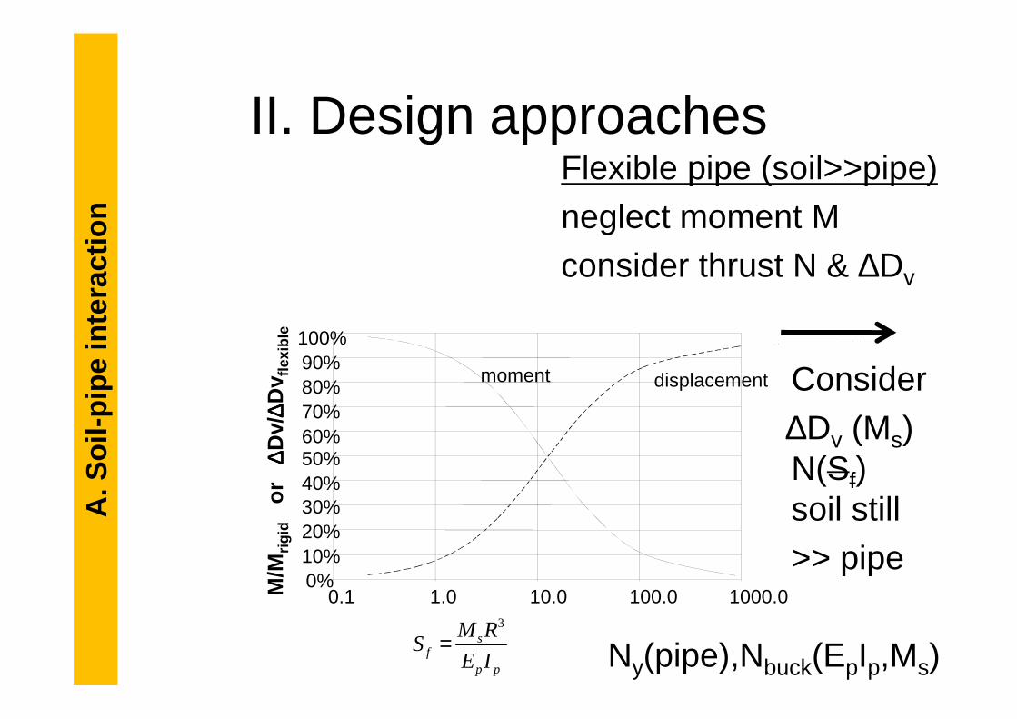
I. Role of soil and pipe stiffnessTransition from rigid (high moment, low deflection) to flexible pipe (low moment, high deflection) controlled by ratio of soil modulus MS to EpIp
pipe
inte
ract
ion
flexi
ble
0%
10%
20%
30%
40%
50%
60%
70%
80%
0.1 1.0 10.0 100.0 1000.0
displacement
A. S
oil-
pipe
inte
ract
ion
pp
sf IE
RMS
3
=
M/M
rigid
or
∆∆ ∆∆Dv/
∆∆ ∆∆Dv f
lexi
ble
Elastic soil-pipe interaction theory (Hoeg, 1968)

II. Design approachesRigid Pipe (pipe>>soil):consider moment M & thrust Nneglect ∆Dv
M(BF,S )
pipe
inte
ract
ion
90%100%
flexi
ble
M(BF,Sf)N(Sf)sincepipe still>>soil
A. S
oil-
pipe
inte
ract
ion
0%10%20%30%40%50%60%70%80%90%
0.1 1.0 10.0 100.0 1000.0
moment displacement
pp
sf IE
RMS
3
=
M/M
rigid
or
∆∆ ∆∆Dv/
∆∆ ∆∆Dv f
lexi
ble
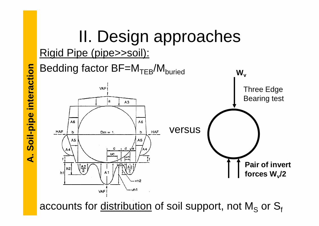
II. Design approachesRigid Pipe (pipe>>soil):Bedding factor BF=MTEB/Mburied
pipe
inte
ract
ion Wv
Three Edge Bearing test
versus
accounts for distribution of soil support, not MS or Sf
A. S
oil-
pipe
inte
ract
ion
Pair of invert forces W v/2
90%100%
II. Design approachesRigid Pipe (pipe>>soil): Flexible pipe (soil>>pipe)consider moment & thrust neglect moment Mneglect ∆Dv consider thrust N & ∆Dv
pipe
inte
ract
ion
flexi
ble
0%10%20%30%40%50%60%70%80%90%
0.1 1.0 10.0 100.0 1000.0
moment displacement Ignore ConsiderMs since ∆Dv (Ms)
N(Sf)soil still
>>soil >> pipe
Ny(pipe),Nbuck(EpIp,Ms)
A. S
oil-
pipe
inte
ract
ion
pp
sf IE
RMS
3
=
M/M
rigid
or
∆∆ ∆∆Dv/
∆∆ ∆∆Dv f
lexi
ble

90%100%
II. Design approachesRigid Pipe (pipe>>soil): Flexible pipe (soil>>pipe)R/C and clay pipe Corrugated steel pipe
Presentation ignoressemi-rigid pipes
pipe
inte
ract
ion
flexi
ble
0%10%20%30%40%50%60%70%80%90%
0.1 1.0 10.0 100.0 1000.0
moment displacement
Ignore
A. S
oil-
pipe
inte
ract
ion
pp
sf IE
RMS
3
=
M/M
rigid
or
∆∆ ∆∆Dv/
∆∆ ∆∆Dv f
lexi
ble

III. Soil propertiesCharacteristics of intact backfill (Ms) well established
by Selig and McGrath (now in AASHTO, AWWA)
pipe
inte
ract
ion
Vertical stress level kPaSoil type RD 7 35 70 140 275 410SW (SP, GW, GP)Granular
85 3.2 3.6 3.9 4.5 5.7 6.990 8.8 10.3 11.2 12.4 14.5 17.2
Three soil types at three densities (% Proctor)Effect of stress levels (burial depth)
A. S
oil-
pipe
inte
ract
ion
Granularmaterials
90 8.8 10.3 11.2 12.4 14.5 17.295 13.8 17.9 20.7 23.8 29.3 34.5
MLSilty backfill
85 2.5 2.7 2.8 3.0 3.5 4.190 4.6 5.1 5.2 5.4 6.2 7.195 9.8 11.5 12.2 13.0 14.4 15.9
CLClay soils
85 0.9 1.2 1.4 1.6 2.0 2.490 1.8 2.2 2.4 2.7 3.2 3.695 3.7 4.3 4.8 5.1 5.6 6.2
B. Deterioration and remaining strength
I. Rigid sewers and culvertsII. Flexible metal storm sewers & culverts
B. D
eter
iora
tion
and
rem
aini
ng s
tren
gth
B. D
eter
iora
tion
and
rem
aini
ng s
tren
gth

I. Rigid sewer pipes
• Clay pipes fractureand deform
• Vitrified clay (glass) isvery durable
B. D
eter
iora
tion
and
rem
aini
ng s
tren
gth
very durable• What are the causes
of clay sewer and R/C pipe failures?
Vitrified clay pipe, Toronto ON
Clay pipes, Ephesus, Turkey
B. D
eter
iora
tion
and
rem
aini
ng s
tren
gth

Likely mechanism:
I. Rigid sewer pipesB
. Det
erio
ratio
n an
d re
mai
ning
str
engt
hB
. Det
erio
ratio
n an
d re
mai
ning
str
engt
h

Likely mechanism:i Joint leakage – ingress of
groundwater or outflow
I. Rigid sewer pipesB
. Det
erio
ratio
n an
d re
mai
ning
str
engt
hB
. Det
erio
ratio
n an
d re
mai
ning
str
engt
h

Likely mechanism:i Joint leakage – ingress of
groundwater or outflowii Erosion of backfill
I. Rigid sewer pipesB
. Det
erio
ratio
n an
d re
mai
ning
str
engt
h
ii Erosion of backfill
B. D
eter
iora
tion
and
rem
aini
ng s
tren
gth

Likely mechanism:i Joint leakage – ingress of
groundwater or outflowii Erosion of backfill
I. Rigid sewer pipesB
. Det
erio
ratio
n an
d re
mai
ning
str
engt
h
ii Erosion of backfilliii Less uniform soil support
B. D
eter
iora
tion
and
rem
aini
ng s
tren
gth

Likely mechanism:i Joint leakage – ingress of
groundwaterii Erosion of backfill
I. Rigid sewer pipesB
. Det
erio
ratio
n an
d re
mai
ning
str
engt
h
ii Erosion of backfilliii Less uniform soil supportiv Moments increase as
Bedding Factor reduces (loads more nonuniform); fracture & accelerated erosion
B. D
eter
iora
tion
and
rem
aini
ng s
tren
gth

Invert erosion
U.K. Tests: invert voids fill with soil from the springline
I. Rigid sewer pipesB
. Det
erio
ratio
n an
d re
mai
ning
str
engt
h
with soil from the springline so springline voids again form
B. D
eter
iora
tion
and
rem
aini
ng s
tren
gth
Gumbel, J., Spasojevic, A., and Mair, R. 2003, Cent rifuge modelling of soil load transfer to flexible sewer liners, Proceedings ASCE Pipeline 2003 Conference, Baltimore, 11 pp.

I. Rigid sewer pipes
Voids Contact Angles:
B. D
eter
iora
tion
and
rem
aini
ng s
tren
gth
Angles:
0o (no void)
30o
60o
90oB. D
eter
iora
tion
and
rem
aini
ng s
tren
gth

255075
100125150175200225250
Perc
enta
ge C
hang
e of
Str
esse
s (%
)
%Moment change with void growth
I. Rigid sewer pipesB
. Det
erio
ratio
n an
d re
mai
ning
str
engt
h
-250-225-200-175-150-125-100-75-50-25
025
0 25 50 75 100
Angle of Voids ( )
Perc
enta
ge C
hang
e of
Str
esse
s (%
)
%
Tan and Moore (2007)Voids Contact Angles
B. D
eter
iora
tion
and
rem
aini
ng s
tren
gth

255075
100125150175200225250
Perc
enta
ge C
hang
e of
Str
esse
s (%
)
Moment tripled
Moment doubled
Interface friction
& Void width
I. Rigid sewer pipesB
. Det
erio
ratio
n an
d re
mai
ning
str
engt
h
-250-225-200-175-150-125-100-75-50-25
025
0 25 50 75 100
Angle of Voids ( )
Perc
enta
ge C
hang
e of
Str
esse
s (%
)
%
Tan and Moore (2007)
B. D
eter
iora
tion
and
rem
aini
ng s
tren
gth
Voids Contact Angles

I. Rigid sewer pipes
Remaining “strength”
Fractured pipe behaves as flexible pipeStructurally stable unless:
B. D
eter
iora
tion
and
rem
aini
ng s
tren
gth
Structurally stable unless:- Soil erosion continues- Segments come loose
→ rehabilitate to preventthese developments
B. D
eter
iora
tion
and
rem
aini
ng s
tren
gth

I. Rigid sewer pipes
Concrete pipe deterioration - sulfuric acidattack (sewer gas) – concrete lost from crown to waterline
B. D
eter
iora
tion
and
rem
aini
ng s
tren
gth
B. D
eter
iora
tion
and
rem
aini
ng s
tren
gth
MacDougall (2012)

I. Rigid sewer pipes
Concrete pipe Concrete loss has littledeterioration effect on moment capacity
at the crown unlessthe steel corrodes
B. D
eter
iora
tion
and
rem
aini
ng s
tren
gth
the steel corrodes
Loss of springlinemoment capacity not usually critical
B. D
eter
iora
tion
and
rem
aini
ng s
tren
gth
MacDougall (2012)

10.0
100.0∆D/D0.2%
0.5%SW95
I. Rigid sewer pipesSoil modulus controls flexible pipe deflection
B. D
eter
iora
tion
and
rem
aini
ng s
tren
gth
0.1
1.0
10.0
1 10
Ms
MP
a 1% 2%
5%
10%
SW90
SW85
B. D
eter
iora
tion
and
rem
aini
ng s
tren
gth
∆∆∆∆DH /D=
Moore (2008)
depth (m)

10.0
100.0∆D/D0.2%
0.5%SW95
I. Rigid sewer pipesDesign modulus to estimate new pipe ∆D/D
B. D
eter
iora
tion
and
rem
aini
ng s
tren
gth
1.2%
0.1
1.0
10.0
1 10
Ms
MP
a 1% 2%
5%
10%
SW90
SW85
B. D
eter
iora
tion
and
rem
aini
ng s
tren
gth
∆∆∆∆DH /D=
Moore (2008)
depth (m)
1.2%
e.g. 4min SW90

10.0
100.0∆D/D0.2%
0.5%SW95
I. Rigid sewer pipesEstimate ∆D/D using CCTV for “effective” Ms
B. D
eter
iora
tion
and
rem
aini
ng s
tren
gth
1.2%
0.1
1.0
10.0
1 10
Ms
MP
a 1% 2%
5%
10%
SW90
SW85
B. D
eter
iora
tion
and
rem
aini
ng s
tren
gth
∆∆∆∆DH /D=
Moore (2008)
depth (m)
1.2%
observe 10%
(8x larger)
infer1.6MPa

I. Rigid sewer pipesFurther finite element analysis to estimatehow erosion changesdeflectionsCalculate soil damage
B. D
eter
iora
tion
and
rem
aini
ng s
tren
gth
Calculate soil damageindex for sands & clay
B. D
eter
iora
tion
and
rem
aini
ng s
tren
gth
erodedH
designH
designS
effectiveS
D
D
M
MSDI
,
,
,
,
∆∆
==
Tan & Moore (2006), Moore (2008)

I. Rigid sewer pipesB
. Det
erio
ratio
n an
d re
mai
ning
str
engt
h
6
7
8
9
10
disp
lace
men
t mul
tiplie
r =
SD
I -1
fine grained backfill
αααα
finebackfill
B. D
eter
iora
tion
and
rem
aini
ng s
tren
gth
Moore (2008)1
2
3
4
5
6
0 30 60 90void angle α (degrees)
disp
lace
men
t mul
tiplie
r =
SD
I
granular backfill
SDI coarsebackfill

I. Rigid sewer pipesB
. Det
erio
ratio
n an
d re
mai
ning
str
engt
h
6
7
8
9
10
disp
lace
men
t mul
tiplie
r =
SD
I -1
fine grained backfill
αααα
finebackfille.g. 8x
for SW
B. D
eter
iora
tion
and
rem
aini
ng s
tren
gth
Moore (2008)1
2
3
4
5
6
0 30 60 90void angle α (degrees)
disp
lace
men
t mul
tiplie
r =
SD
I
granular backfill
SDI coarsebackfill
infer≈90o void

I. Rigid sewer pipesCONCLUSIONS1. Originally designed for moment 2. Fractures as a result of soil erosion
(leaking joints) which increases moments
B. D
eter
iora
tion
and
rem
aini
ng s
tren
gth
(leaking joints) which increases moments3. Sewer gas leads to concrete loss but little
change in capacity until steel corrodes4. Fractured pipe becomes flexible – should
stabilize to prevent further soil erosion5. Infer effective soil modulus or size of
erosion void using ∆Dh,CCTV/∆Dh,design
B. D
eter
iora
tion
and
rem
aini
ng s
tren
gth

II. Corrugated steel pipes
• Many deteriorated steel pipes across Canada (hundreds of thousands)
• Original design life was 25 to 50 years
B. D
eter
iora
tion
and
rem
aini
ng s
tren
gth
Metal culvert,
Hwy 401, ON
Corrosion results in
perforations and this leads to erosion
B. D
eter
iora
tion
and
rem
aini
ng s
tren
gth

II. Corrugated steel pipes
Finite element analysis considering steel loss across invert
B. D
eter
iora
tion
and
rem
aini
ng s
tren
gth
1
90o Invert Corrosion H=3.0m D=2m135o Invert Corrosion H=3.0m D=2m180o Invert Corrosion H=3.0m D=2m90o Invert Corrosion H=3.0m D=4m135o Invert Corrosion H=3.0m D=4m180o Invert Corrosion H=3.0m D=4m
B. D
eter
iora
tion
and
rem
aini
ng s
tren
gth
0
0.2
0.4
0.6
0.8
1
0255075100
% t left
FO
SY C
orro
ded
/ F
OS
Y In
tact
180o Invert Corrosion H=3.0m D=4m90o Invert Corrosion H=3.0m D=6m135o Invert Corrosion H=3.0m D=6m180o Invert Corrosion H=3.0m D=6m90o Invert Corrosion H=1.5m D=4m135o Invert Corrosion H=1.5m D=4m180o Invert Corrosion H=1.5m D=4m90o Invert Corrosion H=10m D=4m135o Invert Corrosion H=10m D=4m180o Invert Corrosion H=10m D=4m
135o180o90o
El Taher and Moore (2008)

II. Corrugated steel pipesB
. Det
erio
ratio
n an
d re
mai
ning
str
engt
h
1
90o Invert Corrosion H=3.0m D=2m135o Invert Corrosion H=3.0m D=2m180o Invert Corrosion H=3.0m D=2m90o Invert Corrosion H=3.0m D=4m135o Invert Corrosion H=3.0m D=4m180o Invert Corrosion H=3.0m D=4m
Finite element analysis considering steel loss across invert – little change in thrust so stability against yield decreases linearly with
wall loss
B. D
eter
iora
tion
and
rem
aini
ng s
tren
gth
0
0.2
0.4
0.6
0.8
1
0255075100
% t left
FO
SY C
orro
ded
/ F
OS
Y In
tact
180o Invert Corrosion H=3.0m D=4m90o Invert Corrosion H=3.0m D=6m135o Invert Corrosion H=3.0m D=6m180o Invert Corrosion H=3.0m D=6m90o Invert Corrosion H=1.5m D=4m135o Invert Corrosion H=1.5m D=4m180o Invert Corrosion H=1.5m D=4m90o Invert Corrosion H=10m D=4m135o Invert Corrosion H=10m D=4m180o Invert Corrosion H=10m D=4m
El Taher and Moore (2008)
Different corrosion angles, culvert diameters and burial depths
wall loss

1
II. Corrugated steel pipesB
. Det
erio
ratio
n an
d re
mai
ning
str
engt
h
Finite element analysis of buckling strength change with corrosion – little change untilcorrosion is substantial
0
0.2
0.4
0.6
0.8
1
0255075100
% t left
Ncr
,FE
A C
orro
ded
/ N
cr,F
EA
Inta
ct
90o Invert Corrosion H=3.0m D=4m135o Invert Corrosion H=3.0m D=4m180o Invert Corrosion H=3.0m D=4m
B. D
eter
iora
tion
and
rem
aini
ng s
tren
gth
El Taher and Moore (2008)

II. Corrugated steel pipesB
. Det
erio
ratio
n an
d re
mai
ning
str
engt
h
Finite element analysis of buckling strength- erosion can destabilise the culvert
and the overlying pavement
B. D
eter
iora
tion
and
rem
aini
ng s
tren
gth
El Taher (2008)
Erosion only
with haunch corrosionwith springline corrosion

II. Corrugated steel pipesCONCLUSIONS1. Original design considers thrust2. Corrosion reduces stability against yield
linearly with respect to wall loss
B. D
eter
iora
tion
and
rem
aini
ng s
tren
gth
linearly with respect to wall loss3. Erosion can dramatically reduce buckling
strength and lead to instability4. Erosion can also compromise the
overlying pavement5. Culvert repair to stabilize soil and pipe
B. D
eter
iora
tion
and
rem
aini
ng s
tren
gth

C. Repair using Liners
I. Lining procedures- Sewers and culverts- Water pipes
C. R
epai
r us
ing
liner
s
II. Design considerations- Cast in place liners within gravity flow pipes- Slip-liners within gravity flow pipes- Rigid (& semi-rigid) spray on liners within
gravity flow pipes
C. R
epai
r us
ing
liner
s

Slip-liningC
. Rep
air
usin
g lin
ers
Use any preformed pipe (metal, polymer, …)Grout the space between pipes
HDPE pipe slip-lining of corrugated steel pipe, nea r Kaladar, ON
C. R
epai
r us
ing
liner
s

Cured-in-place lining - sewersC
. Rep
air
usin
g lin
ers
• Felt impregnated with epoxy or other resin• Hot water, steam, or UV light cured• Circular prismatic shapes easy; also non-circular and
variable diameter liners (special expertise needed)
Repaired sewer line Toronto, ON
C. R
epai
r us
ing
liner
s

Prepare service connections(locate and plug)Insert resin impregnated liner
Cure with hotwater
Cured in place lining - pressure pipeC
. Rep
air
usin
g lin
ers
water
Liner of excess length so wavesdevelop – these control strength
Technology trialHamilton ON, 2004
Strength testingQueen’s, 2008
C. R
epai
r us
ing
liner
s

120” CMP CulvertPanel Lok IIIE
Strip-wound liningC
. Rep
air
usin
g lin
ers
Panel Lok IIIE
Polymer strips welded,glued or locked togetherGrout or reversewind to treat gap
Courtesy Danby
www.dot.ca.gov
C. R
epai
r us
ing
liner
s
Courtesy Danby

Spray on linersC
. Rep
air
usin
g lin
ers
- Stiff (structural) Portland cement liner sprayed within corrugated steel and reinforced concrete culverts and sewers (CO)
- Flexible polymer sprays also used to seal leaks (e.g. joints)
1.2m corrugated steel pipe from 407ETR
Pipe after repair using GeoTree liner
C. R
epai
r us
ing
liner
s

Deform-reform liningFold and form lining & Swage lining
www.dot.ca.gov
C. R
epai
r us
ing
liner
s
Thermoplastic tube folded, pulled into place,then opened out, or squeezed through cone.
www.dot.ca.gov
www.ultraliner.com
C. R
epai
r us
ing
liner
s

II. Design considerations
Geotechnical aspects of liners in gravity flow pipes
• Cured in place liners• Slip liners
C. R
epai
r us
ing
liner
s
• Slip liners• Sprayed liners• Discussion of F1216.C
. Rep
air
usin
g lin
ers

Two potential demands (loads)
i. Will external fluid loads reach the liner?
Cured in place liners
ExternalPressure
C. R
epai
r us
ing
liner
s
loads reach the liner?
How?Grout pressure (construction)Groundwater through fractures
FracturedHost Pipe
FlexibleLiner
C. R
epai
r us
ing
liner
s

Two potential demands (loads)
ii. External earth loads
• overburden pressure FlexibleEarth Load
C. R
epai
r us
ing
liner
sCured in place liners
• overburden pressurechanges after lining
• vehicle loads DamagedCulvert
FlexibleLiner
C. R
epai
r us
ing
liner
s
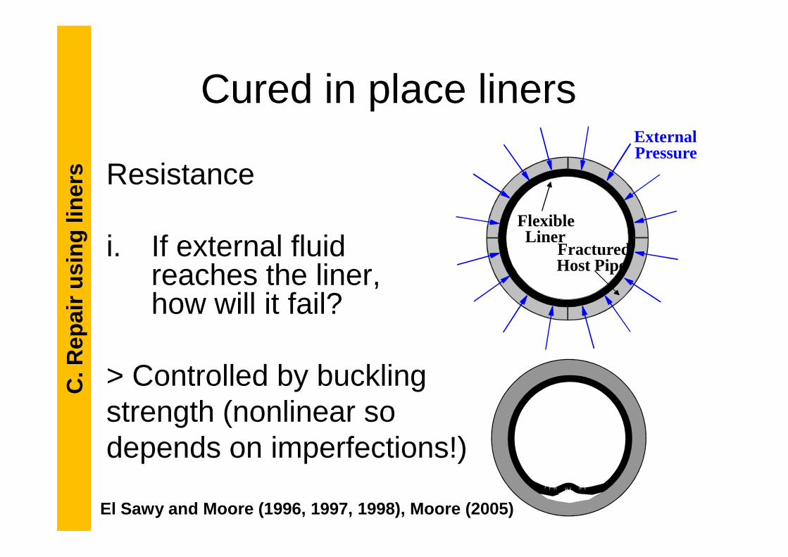
ExternalPressure
FracturedHost Pipe
FlexibleLiner
Resistance
i. If external fluid reaches the liner,
C. R
epai
r us
ing
liner
sCured in place liners
reaches the liner, how will it fail?
> Controlled by buckling strength (nonlinear so depends on imperfections!)
C. R
epai
r us
ing
liner
s
El Sawy and Moore (1996, 1997, 1998), Moore (2005)

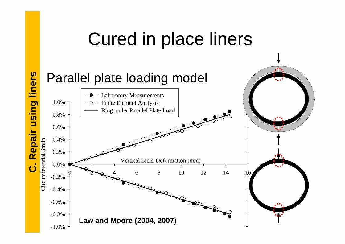
Resistance
ii. If external earth and vehicle loads reach
C. R
epai
r us
ing
liner
sCured in place liners
vehicle loads reach the pipe, how will itfail?
> Local bending where vertical
diameter decreases after repair
C. R
epai
r us
ing
liner
s
Law and Moore (2004, 2007)
C. R
epai
r us
ing
liner
s
0.8%
1.0%Laboratory MeasurementsFinite Element AnalysisRing under Parallel Plate Load
Parallel plate loading model
Cured in place linersC
. Rep
air
usin
g lin
ers
Vertical Liner Deformation (mm)
0 2 4 6 8 10 12 14 16
Cir
cum
fere
ntia
l Str
ain
-1.0%
-0.8%
-0.6%
-0.4%
-0.2%
0.0%
0.2%
0.4%
0.6%
Law and Moore (2004, 2007)

Bending strain in liner
C. R
epai
r us
ing
liner
s
allowlinerhostpipeH
D
t
OD
t
D
D εε <−∆−= ))(2
1)((3.4max
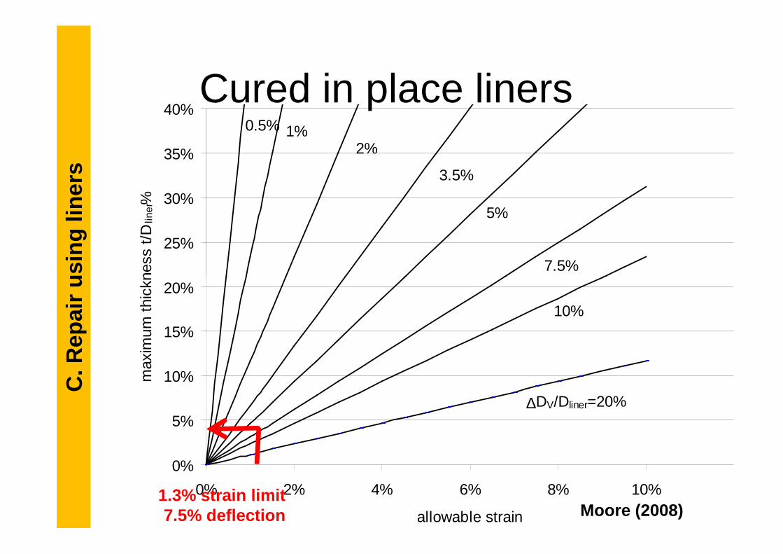
Cured in place liners
- Sets a limit on maximum allowable liner thickness since deflection is imposed by the soil- Higher tensions than if designed as direct buried polymer pipe!
C. R
epai
r us
ing
liner
s
allowlinerhostpipeliner DODD
εε <−−= ))(1)((3.4max
Law and Moore (2004, 2007)
C. R
epai
r us
ing
liner
sCured in place liners
25%
30%
35%
40%
max
imum
thic
knes
s t/
Dlin
er%
7.5%
5%
3.5%
2%
0.5% 1%
C. R
epai
r us
ing
liner
s
Moore (2008)
0%
5%
10%
15%
20%
0% 2% 4% 6% 8% 10%
allowable strain
max
imum
thic
knes
s t/
D
∆DV/Dliner=20%
10%
1.3% strain limit7.5% deflection

Exhumed liner samples (12 in
total).
• ASTM standard for cured in place liners• Considers liner buckling using empirical
‘enhancement factor’ K=7 (Insituform liner)• K=7 incorrectly used for many liners (may
Use of F1216C
. Rep
air
usin
g lin
ers
Liner inflation and curing using hot water
total).• K=7 incorrectly used for many liners (may be <4 for thermoplastic liners!)
• Uses pipe supported by spring model to define buckling strength under earth load
• However, earth load buckling not possible since the old sewer carries thrusts, and the spring model is also poor
C. R
epai
r us
ing
liner
s

Exhumed liner samples (12 in
total).
• To seal joints & prevent leakage & erosion• No established design method available• Need to consider joint movements• Saiyar, Moore & Take (2010) gives
Polymer spraysC
. Rep
air
usin
g lin
ers
Liner inflation and curing using hot water
total).• Saiyar, Moore & Take (2010) gives estimate of rotation as a function of the ground movements
• Becerril & Moore(2013ab),Yu & Moore(2013) & Moore et al. (2012) give joint response to surface and earth loads
C. R
epai
r us
ing
liner
s

Exhumed liner samples (12 in
total).
1. 407 ETR project examining spray-on-liner• Strength evaluation and design procedure
for selection of wall thickness – completion in July 2013
Current projectsC
. Rep
air
usin
g lin
ers
Liner inflation and curing using hot water
total).in July 20132. NCHRP 14-19 for US DOTs • Guide for assessment of deteriorated
culverts and sewers and their repair• Develop designs for slip & cured in place
liners – completion in December 2013
C. R
epai
r us
ing
liner
s

Damaged pipe tests before and after repair
C. R
epai
r us
ing
liner
sSlip-liners
C. R
epai
r us
ing
liner
s
Simpson, Hoult and Moore (2013)

- Research on low strength and high strength grouts
- Q: Is the liner a permanent form for the grout, or does it form part of the long
C. R
epai
r us
ing
liner
sSlip-liners
grout, or does it form part of the long term structural system?
- Q: Is there full or partial composite action (what are the interactions between soil-old pipe-grout-liner?)
- Q: Effect of a grout-filled void?
C. R
epai
r us
ing
liner
s
Mai, Hoult and Moore (2012), Simpson, Hoult and Moo re (2013)

Damaged pipe tests before and after repair
C. R
epai
r us
ing
liner
sSlip-liners
C. R
epai
r us
ing
liner
s
Simpson, Hoult and Moore (2013)

C. Repair using linersCONCLUSIONS1. There are many existing lining methods &
new procedures continue to be developed2. Design of cured in place liners well
C. R
epai
r us
ing
liner
s
2. Design of cured in place liners well established, but earth load effects need re-evaluation to consider local bending(continue to use F1216 earth load buckling until code changes, to avoid liability)
3. Rational design method for slip liners considering interactions being developed
C. R
epai
r us
ing
liner
s

C. Repair using linersCONCLUSIONS4. Design for buckling using ASTM F1216 &
K=7 OK for CIP thermosetting liners but often inappropriate for other liner products
C. R
epai
r us
ing
liner
s
5. Not necessarily conservative to design liner as direct burial pipe – ignores interactions between liner and old
6. Erosion effects (voids) also being examined though further work needed
C. R
epai
r us
ing
liner
s

Acknowledgements
• Natural Sciences and Engineering Research Council (NSERC), Canada Foundation for Innovation, Province of Ontario
• NSERC, 407ETR, MTO, Cities of Hamilton and • NSERC, 407ETR, MTO, Cities of Hamilton and London, US Academy of Sciences
• Collaborator Drs Neil Hoult & Andy Take• Current and former students David Becerril
Garcia, Mohamed El Taher, Michael Law, Van Mai, Bryan Simpson, Masoumeh Saiyar, & Zheng Tan.

Publications (see www.geoeng.ca)
• Becerri Garcia & Moore 2013 Transportation Research record (to appear)• Becerri Garcia & Moore 2013 Journal of Geotechnical and Geoenvir. Eng (to appear)• Law & Moore 2007 Tunneling and Underground Space Technology,22(5) 655–665.• Law & Moore 2003 North American No Dig, Las Vegas, NV.• Moore & El-Sawy 1996 Transportation Research Record 1541, 127-132• El Sawy & Moore 1997 Annual conf. Pipeline Division, ASCE, Boston, pp. 416-423• El-Sawy & Moore 1998 Journal of Structural Engineering, ASCE, 124(11), 1350-1357• El Taher, M. and Moore, I.D. 2008. Transportation Research Record, 2050, 157-166• El Taher, M. and Moore, I.D. 2008. Transportation Research Record, 2050, 157-166• Mai, Hoult, & Moore 2012. North American NoDig 2012, Orlando, Paper A-4-03.• Moore 2005. Buried Infrastructure Repair Using Liners: Construction Techniques,
Struct. & Geotech. Issues, 11th Int.Symposium, Cairo, Egypt, May• Moore, Becerril Garcia, Sezen & Sheldon, 2012, NCHRP Web only document 190.• Simpson, Hoult & Moore 2013 North American NoDig 2013, Sacramento, CA• Saiyar, Moore & Take 2010. Int. No-Dig 2010, ISTT Singapore, paper 43, 7pp. • Tan & Moore 2007. Transportatn Research Board Ann.Conf., Washington D.C. 29pp• Wang & Moore 2013. Journal of Geotechnical and Geoenvir. Eng (to appear)

Ian Moore, PhD, PEng
Deterioration processes, remaining strength and repair
of buried pipes
Ian Moore, PhD, PEngProfessor and Canada Research Chair
GeoEngineering Centre at Queen’s-RMC
www.geoeng.ca