detection of stator winding fault in induction motor using...
TRANSCRIPT
Turk J Elec Eng & Comp Sci
(2015) 23: 1263 – 1271
c⃝ TUBITAK
doi:10.3906/elk-1304-72
Turkish Journal of Electrical Engineering & Computer Sciences
http :// journa l s . tub i tak .gov . t r/e lektr ik/
Research Article
Detection of stator winding fault in induction motor using instantaneous power
signature analysis
Ahmet KUCUKER∗, Mehmet BAYRAKDepartment of Electrical-Electronics Engineering, Faculty of Engineering, Sakarya University, Sakarya, Turkey
Received: 09.04.2013 • Accepted/Published Online: 17.06.2013 • Printed: 28.08.2015
Abstract: Stator interturn faults are one of the most common faults occurring in induction motors. Early detection of
interturn short circuit is important to reduce repair costs. Axial leakage monitoring, zero-sequence components, negative
sequence current, and motor current signature analysis have been used for fault detection in early states. In the paper,
the instantaneous power signature analysis technique is used to detect these faults, and experimental results for healthy
and faulty motors are shown and discussed.
Key words: Fault detection, instantaneous power signature analysis, stator winding faults, induction motors
1. Introduction
Induction motors are a major irreplaceable part of industry and have an important role in the processes and
production lines in many areas of industry. Hence, unexpected failures in these motors may create major
problems. The Institute of Electrical and Electronics Engineers (IEEE) and the Electric Power Research
Institute (EPRI) have done authoritative studies on this issue. The percentage of failures by component are
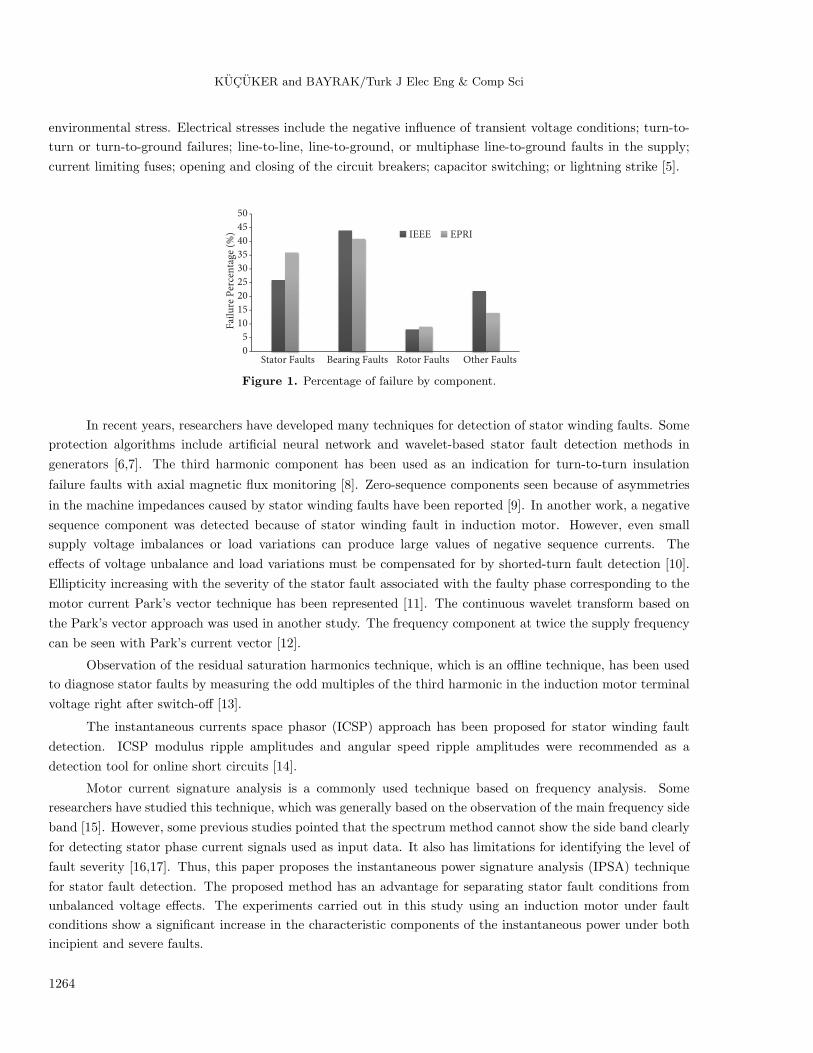
given in Figure 1. Stator faults have 26% rates according to IEEE and 41% rates according to EPRI [1–3].
Sudden failures generally occur due to internal and external motor faults. The essential internal faults can
broadly be classified as follows [4]:
• Stator winding faults,
• Rotor bar faults,
• Bearing faults,
• Mechanical imbalances.
Stator faults are caused by a combination of thermal, electrical, mechanical, and environmental stresses.
One of the thermal stresses is thermal aging. An increase in temperature accelerates the aging process and thus
reduces the lifetime of the stator windings. Another thermal stress is thermal overloading, which depends on
unbalanced phase voltages, overloading, or ambient temperature. Mechanical stresses include coil movement
and strikes from the rotor, bearing failures, shaft deflection, and eccentricity problems [5]. High humidity,
aggressive chemicals, radiation from nuclear plants, or the salt level in seashore applications can be defined as
∗Correspondence: [email protected]
1263
KUCUKER and BAYRAK/Turk J Elec Eng & Comp Sci
environmental stress. Electrical stresses include the negative influence of transient voltage conditions; turn-to-
turn or turn-to-ground failures; line-to-line, line-to-ground, or multiphase line-to-ground faults in the supply;
current limiting fuses; opening and closing of the circuit breakers; capacitor switching; or lightning strike [5].
0
5
10
15
20
25
30
35
40
45
50
Stator Faults Bearing Faults Rotor Faults Other Faults
Fai
lure
Per
cen
tage
(%
)
IEEE EPRI
Figure 1. Percentage of failure by component.
In recent years, researchers have developed many techniques for detection of stator winding faults. Some
protection algorithms include artificial neural network and wavelet-based stator fault detection methods in
generators [6,7]. The third harmonic component has been used as an indication for turn-to-turn insulation
failure faults with axial magnetic flux monitoring [8]. Zero-sequence components seen because of asymmetries
in the machine impedances caused by stator winding faults have been reported [9]. In another work, a negative
sequence component was detected because of stator winding fault in induction motor. However, even small
supply voltage imbalances or load variations can produce large values of negative sequence currents. The
effects of voltage unbalance and load variations must be compensated for by shorted-turn fault detection [10].
Ellipticity increasing with the severity of the stator fault associated with the faulty phase corresponding to the
motor current Park’s vector technique has been represented [11]. The continuous wavelet transform based on
the Park’s vector approach was used in another study. The frequency component at twice the supply frequency
can be seen with Park’s current vector [12].
Observation of the residual saturation harmonics technique, which is an offline technique, has been used
to diagnose stator faults by measuring the odd multiples of the third harmonic in the induction motor terminal
voltage right after switch-off [13].
The instantaneous currents space phasor (ICSP) approach has been proposed for stator winding fault
detection. ICSP modulus ripple amplitudes and angular speed ripple amplitudes were recommended as a
detection tool for online short circuits [14].
Motor current signature analysis is a commonly used technique based on frequency analysis. Some
researchers have studied this technique, which was generally based on the observation of the main frequency side
band [15]. However, some previous studies pointed that the spectrum method cannot show the side band clearly
for detecting stator phase current signals used as input data. It also has limitations for identifying the level of
fault severity [16,17]. Thus, this paper proposes the instantaneous power signature analysis (IPSA) technique
for stator fault detection. The proposed method has an advantage for separating stator fault conditions from
unbalanced voltage effects. The experiments carried out in this study using an induction motor under fault
conditions show a significant increase in the characteristic components of the instantaneous power under both
incipient and severe faults.
1264

KUCUKER and BAYRAK/Turk J Elec Eng & Comp Sci
2. The proposed detection method
This paper proposes the use of instantaneous power analysis for detection of stator winding faults in induction
motors. The IPSA method is examined at various motor load levels. During the implementation of this
method, voltages and currents are necessary for implementing the instantaneous power signature. Suppose that
an induction motor is energized by an ideal three-phase voltage. v(t) is the voltage between any two phases
and i(t) is the current of these phases; these are given by Eqs. (1) and (2):
v(t) = Um cos(2πfst), (1)
i(t) = Im cos(2πfst− ϕ), (2)
where Um is the maximum value of the supply line to line voltage, Im is the maximum value of the supply
current, fs is the supply frequency, and ϕ is the initial phase angle of the supply current.
Partial instantaneous power p0(t) can be written with Eqs (3) and (4).
p0(t) = v(t).i(t) (3)
p0(t) =
√3
2UmIm [cos (2π(2f)t− ϕ) + cos (ϕ)] (4)
The total instantaneous power of a healthy induction motor can be calculated by Eq. (5) using the three-phase
measured instantaneous voltages and currents.
ptot = v1(t)i1(t) + v2(t)i2(t) + v3(t)i3(t) (5)
The effects of stator faults cause characteristic side band currents in the current spectrum. fscf , the frequency
component, is a function of the short circuit and is given by Eq. (6) [18]:
fscf = fs
(k ± n
p/2(1− s)
), (6)
where fr is the rotational frequency, fs is the supply frequency, s is the slip, p is the number of poles, and n
and kare two parameters (n = 1,2,3. . . .. , k = 1,3,5.. . . ).
Rotational frequency fr can be defined as:
fr =1− s
p/2fs. (7)
If a stator winding short circuit faults takes place in induction motor, fault characteristic components at fscf,i
appear in the stator current as given by Eq. (8) [18,19].
fscf,i = k.fs ± nfr (8)
fscfp is the right side band frequency and fscfn is the left side band frequency, as shown in Eqs. (9) and (10).
fscfp = k.fs + nfr (9)
fscfn = k.fs − nfr (10)
1265
KUCUKER and BAYRAK/Turk J Elec Eng & Comp Sci
fscf,p is the fault characteristic component in the power spectrum and can be defined as:
fscf,p = 2.k.fs ± nfr (11)
Stator winding short circuited induction motor current iscf can be expressed as:
iscf (t) =
Im cos [2πft− θ] +
∞∑k=1
{Iscfp cos [2πfscfpt− αscfp] +
Iscfn cos [2πfscfnt− αscfn]
} (12)
where Iscfp is the maximum value of the component at a frequency of (k.fs + nfr), Iscfn is the maximum
value of the component at a frequency of (k.fs−nfr), αscfp is the phase angle of the component at a frequency
of (k.fs + nfr), and αscfn is the maximum value of the component at a frequency of (k.fs − nfr).
The equation for the partial instantaneous power in the case of stator winding short circuit fault is given
by Eq. (13) [18,20]. It can be seen that the instantaneous power spectrum contains an additional component
at the modulation frequency.
p(t) =
√32 Um1Im1 [cos [2(2πf)t− ϕ] + cosϕ] +
∞∑n=1
Um1Iscfn
cos
[(2k (2πfs)−n (2πfr)
)t− ϕscfn
]+cos [n (2πfr) t+ ϕscfn]
+Um1Iscfp
cos
[(2k (2πfs)+
n (2πfr)
)t− ϕscfp
]+cos [n (2πfr) t− ϕscfp]
(13)
3. Experimental results
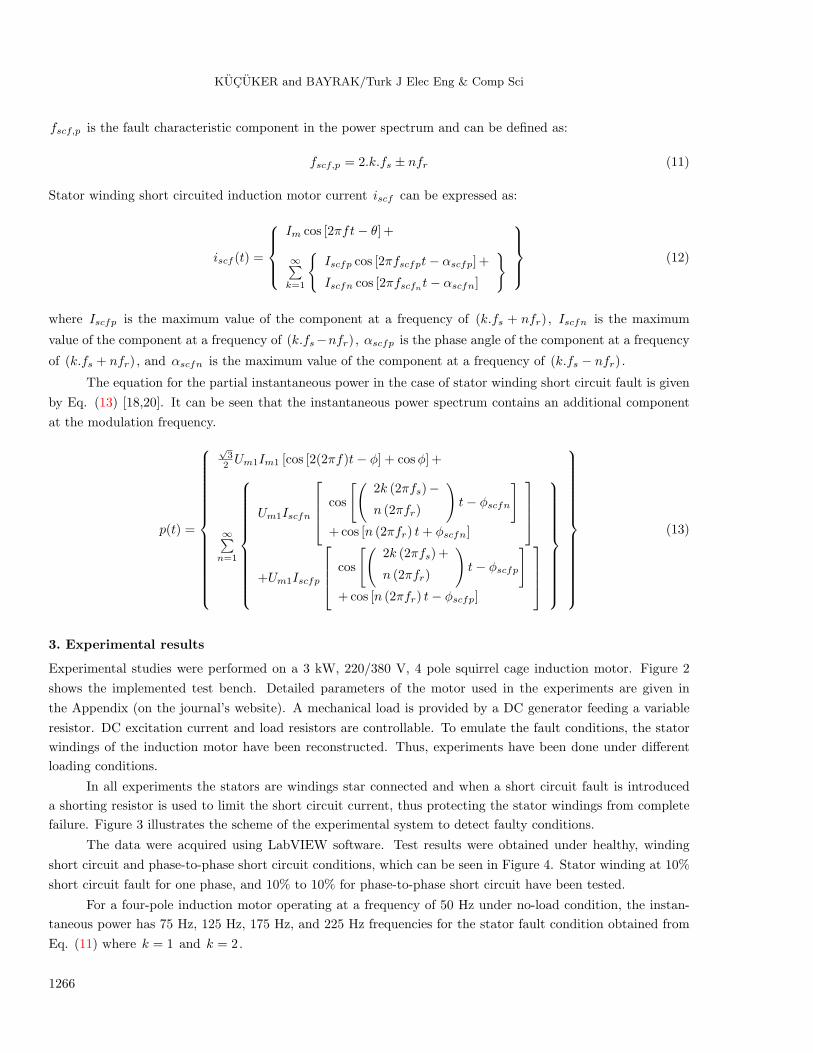
Experimental studies were performed on a 3 kW, 220/380 V, 4 pole squirrel cage induction motor. Figure 2
shows the implemented test bench. Detailed parameters of the motor used in the experiments are given in
the Appendix (on the journal’s website). A mechanical load is provided by a DC generator feeding a variable
resistor. DC excitation current and load resistors are controllable. To emulate the fault conditions, the stator
windings of the induction motor have been reconstructed. Thus, experiments have been done under different
loading conditions.
In all experiments the stators are windings star connected and when a short circuit fault is introduced
a shorting resistor is used to limit the short circuit current, thus protecting the stator windings from complete
failure. Figure 3 illustrates the scheme of the experimental system to detect faulty conditions.
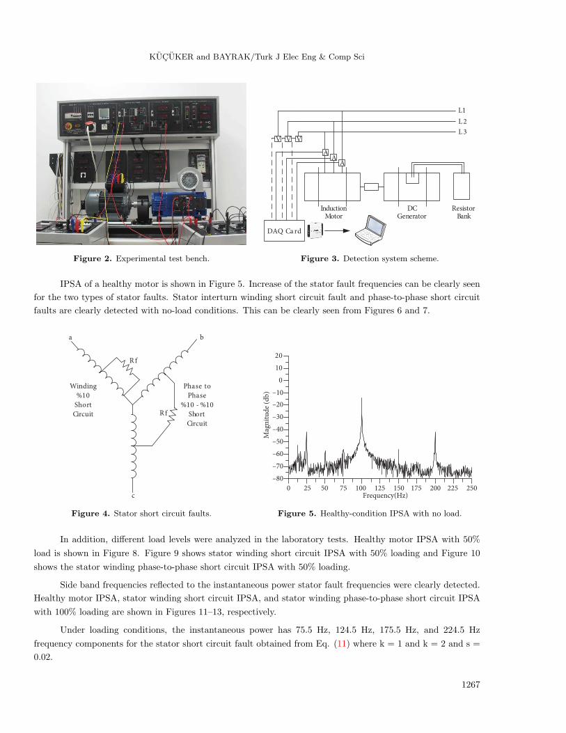
The data were acquired using LabVIEW software. Test results were obtained under healthy, winding
short circuit and phase-to-phase short circuit conditions, which can be seen in Figure 4. Stator winding at 10%
short circuit fault for one phase, and 10% to 10% for phase-to-phase short circuit have been tested.
For a four-pole induction motor operating at a frequency of 50 Hz under no-load condition, the instan-
taneous power has 75 Hz, 125 Hz, 175 Hz, and 225 Hz frequencies for the stator fault condition obtained from
Eq. (11) where k = 1 and k = 2.
1266
KUCUKER and BAYRAK/Turk J Elec Eng & Comp Sci
L1
ResistorBank
DCGenerator
InductionMotor
V V V
AA
A
DAQ Ca rd
L 2
L 3
Figure 2. Experimental test bench. Figure 3. Detection system scheme.
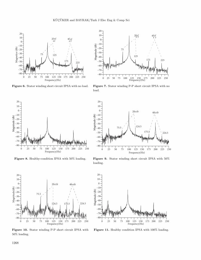
IPSA of a healthy motor is shown in Figure 5. Increase of the stator fault frequencies can be clearly seen
for the two types of stator faults. Stator interturn winding short circuit fault and phase-to-phase short circuit
faults are clearly detected with no-load conditions. This can be clearly seen from Figures 6 and 7.
a b
R f
R f
c
Phase to
Phase
%10 - %10
Short
Circuit
Winding
%10
Short
Circuit
0 25 50 75 100 125 150 175 200 225 250
Mag
nit
ud
e (d
b)
Frequency(Hz)
–80
–70
–60
–50
–40
–30
–20
–10
0
10
20
Figure 4. Stator short circuit faults. Figure 5. Healthy-condition IPSA with no load.
In addition, different load levels were analyzed in the laboratory tests. Healthy motor IPSA with 50%
load is shown in Figure 8. Figure 9 shows stator winding short circuit IPSA with 50% loading and Figure 10
shows the stator winding phase-to-phase short circuit IPSA with 50% loading.
Side band frequencies reflected to the instantaneous power stator fault frequencies were clearly detected.
Healthy motor IPSA, stator winding short circuit IPSA, and stator winding phase-to-phase short circuit IPSA
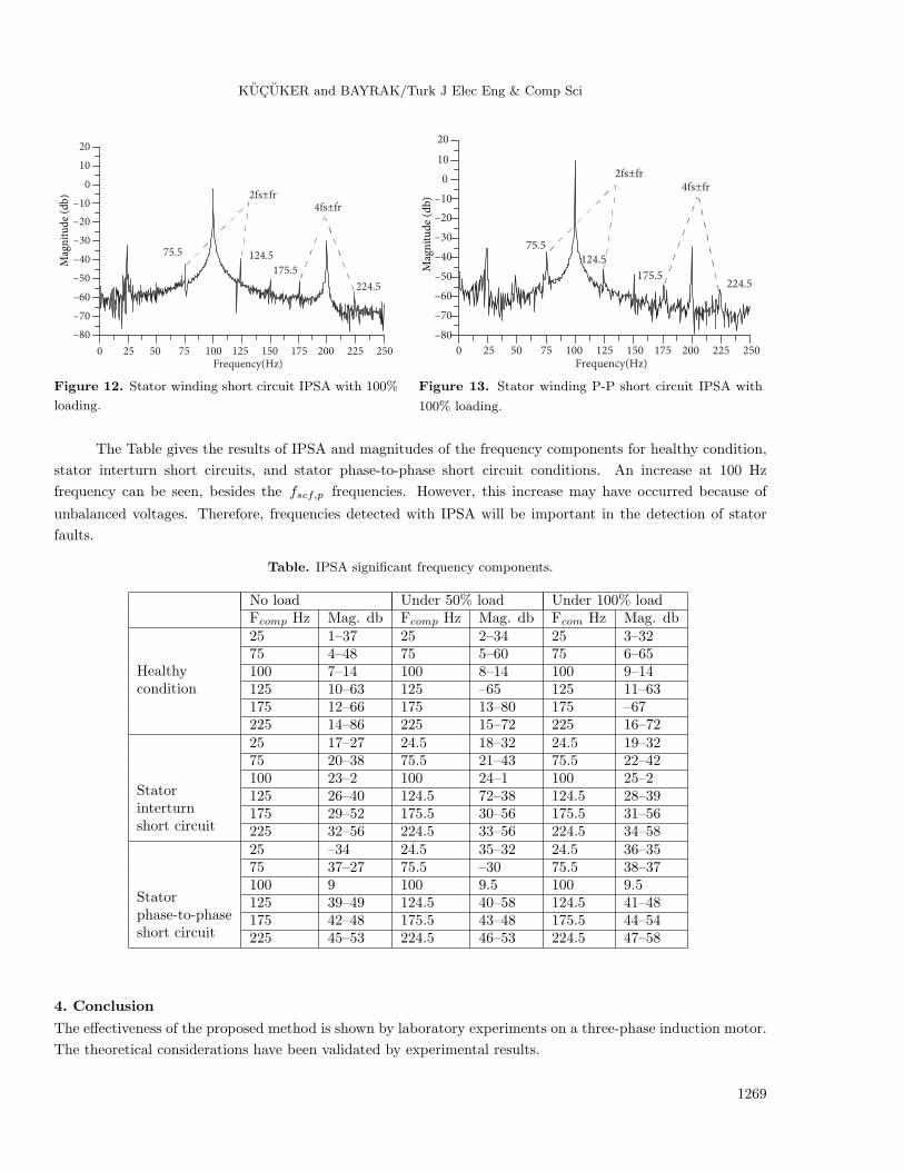
with 100% loading are shown in Figures 11–13, respectively.
Under loading conditions, the instantaneous power has 75.5 Hz, 124.5 Hz, 175.5 Hz, and 224.5 Hz
frequency components for the stator short circuit fault obtained from Eq. (11) where k = 1 and k = 2 and s =
0.02.
1267
KUCUKER and BAYRAK/Turk J Elec Eng & Comp Sci
0 25 50 75 100 125 150 175 200 225 250Frequency(Hz)
–80
–70
–60
–50
–40
–30
–20
–10
0
10
20
Mag
net
ice
(db
)
2fs±fr
4fs±fr
75 125
175225
0 25 50 75 100 125 150 175 200 225 250Frequency(Hz)
–80
–70
–60
–50
–40
–30
–20
–10
0
10
20
2fs±f
r4f
s±f
r
75
125
175 225Mag
nit
ud
e (d
b)
Figure 6. Stator winding short circuit IPSA with no load. Figure 7. Stator winding P-P short circuit IPSA with no
load.
0 25 50 75 100 125 150 175 200 225 250Frequency(Hz)
–80
–70
–60
–50
–40
–30
–20
–10
0
10
20
Mag
nit
ud
e (d
b)
0 25 50 75 100 125 150 175 200 225 250
Frequency(Hz)
–80
–70
–60
–50
–40
–30
–20
–10
0
10
20
2fs±fr 4fs±fr
75.5 124.5
175.5 224.5
Mag
nit
ud
e (d
b)
Figure 8. Healthy-condition IPSA with 50% loading. Figure 9. Stator winding short circuit IPSA with 50%
loading.
0 25 50 75 100 125 150 175 200 225 250Frequency(Hz)
–80
–70
–60
–50
–40
–30
–20
–10
0
10
20
Mag
nit
ud
e(d
b)
2fs±fr 4fs±fr
75.5
124.5 175.5 224.5
0 25 50 75 100 125 150 175 200 225 250Frequency(Hz)
–80
–70
–60
–50
–40
–30
–20
–10
0
10
20
Mag
nit
ud
e (d
b)
Figure 10. Stator winding P-P short circuit IPSA with
50% loading.
Figure 11. Healthy condition IPSA with 100% loading.
1268
KUCUKER and BAYRAK/Turk J Elec Eng & Comp Sci
0 25 50 75 100 125 150 175 200 225 250Frequency(Hz)
–80
–70
–60
–50
–40
–30
–20
–10
0
10
20
2fs±fr4fs±fr
75.5 124.5
175.5
224.5
Mag
nit
ud
e (d
b)
0 25 50 75 100 125 150 175 200 225 250Frequency(Hz)
–80
–70
–60
–50
–40
–30
–20
–10
0
10
20
2fs±fr4fs±fr
75.5124.5
175.5224.5
Mag
nit
ud
e (d
b)
Figure 12. Stator winding short circuit IPSA with 100%
loading.
Figure 13. Stator winding P-P short circuit IPSA with
100% loading.
The Table gives the results of IPSA and magnitudes of the frequency components for healthy condition,
stator interturn short circuits, and stator phase-to-phase short circuit conditions. An increase at 100 Hz
frequency can be seen, besides the fscf,p frequencies. However, this increase may have occurred because of
unbalanced voltages. Therefore, frequencies detected with IPSA will be important in the detection of stator
faults.
Table. IPSA significant frequency components.
No load Under 50% load Under 100% loadFcomp Hz Mag. db Fcomp Hz Mag. db Fcom Hz Mag. db
Healthy
25 1–37 25 2–34 25 3–32
condition
75 4–48 75 5–60 75 6–65100 7–14 100 8–14 100 9–14125 10–63 125 –65 125 11–63175 12–66 175 13–80 175 –67225 14–86 225 15–72 225 16–72
Stator
25 17–27 24.5 18–32 24.5 19–32
interturn
75 20–38 75.5 21–43 75.5 22–42
short circuit
100 23–2 100 24–1 100 25–2125 26–40 124.5 72–38 124.5 28–39175 29–52 175.5 30–56 175.5 31–56225 32–56 224.5 33–56 224.5 34–58
Stator
25 –34 24.5 35–32 24.5 36–35
phase-to-phase
75 37–27 75.5 –30 75.5 38–37
short circuit
100 9 100 9.5 100 9.5125 39–49 124.5 40–58 124.5 41–48175 42–48 175.5 43–48 175.5 44–54225 45–53 224.5 46–53 224.5 47–58
4. Conclusion
The effectiveness of the proposed method is shown by laboratory experiments on a three-phase induction motor.
The theoretical considerations have been validated by experimental results.
1269

KUCUKER and BAYRAK/Turk J Elec Eng & Comp Sci
Results have shown that stator short circuit faults in an induction motor could be detected using simple
and low-cost techniques that utilize the instantaneous power measurements. The presence of stator short circuit
faults was detected by the increase in the specific fault frequencies in instantaneous power measurements. Phase-
to-phase short circuit fault frequency magnitudes were more distinguishable than stator winding interturn short
circuit fault frequency magnitudes.
In other respects, the use of instantaneous power provides information about the current and voltage
values, which may be important when unbalanced voltage, voltage sags, and other abnormal electrical faults
occured.
Appendix
Parameters of motor used in the experiments.
Rated power 3 kW
Rated voltage 220 V
Rated current 6.45 ARated frequency 50 Hz
Rated speed 1405 r/min
Number of poles 4
Stator connection wye
IA /IN 5.0
MA/MN 2.4
J 0.005 kgm2
References
[1] IAS Motor Reliability Working Group. Report of large motor reliability survey of industrial and commercial
installations, Part 1. IEEE T Ind Appl 1985; 21: 853–864.
[2] IAS Motor Reliability Working Group. Report of large motor reliability survey of industrial and commercial
installations, Part II. IEEE T Ind Appl 1985; 21: 865–872.
[3] IAS Motor Reliability Working Group. Report of large motor reliability survey of industrial and commercial
installations, Part III. IEEE T Ind Appl 1987; 23: 153–158.
[4] Bayrak M, Kucuker A. Detection of rotor bar corrosion in three phase asynchronous motors using wavelet analysis.
In: MEPS 2010 Modern Electric Power Systems Proceedings of the International Symposium; 20-22 September
2010; Wroclaw, Poland. pp. 1–5.
[5] Grubic S, Aller JM, Lu B, Habetler TG. A survey on testing and monitoring methods for stator insulation systems
of low-voltage induction machines focusing on turn insulation problems. IEEE T Ind Electron 2008; 55: 4127–4136.
[6] Khan A, Ozgonenel O, Rahman MA. Wavelet transform based protection of stator faults in synchronous generators.
Electr Pow Compo Sys 2007, 35: 625–637.
[7] Ozgonenel O, Yalcın T. A complete motor protection algorithm based on PCA and ANN: a real time study. Turk
J Electr Eng Co 2011, 19: 317–334.
[8] Toni K, Slobodan M, Aleksandar B. Detection of turn to turn faults in stator winding with axial magnetic flux in
induction motors. In: IEEE Electric Machines & Drives Conference; 3–5 May 2007; Antalya, Turkey. New York,
NY, USA: IEEE. pp. 826–829.
[9] Briz F, Degner MW, Garcia P, Dicz AB. Induction machine diagnostics using zero sequence component. In: IEEE
Industry Applications Conference; 2–6 October 2005; Kowloon, Hong Kong. New York, NY, USA: IEEE. pp. 34–41.
1270

KUCUKER and BAYRAK/Turk J Elec Eng & Comp Sci
[10] Bakhri S, Ertugrul N, Soong WL, Arkan M. Investigation of negative sequence components for stator shorted turn
detection in induction motors. In: 20th Australasian Universities Power Engineering Conference; 5–8 December
2010; Christchurch, New Zealand. pp. 1–6.
[11] Cardoso AJM, Cruz SMA, Fonseca DSB. Inter-turn stator winding fault diagnosis in three-phase induction motors,
by park’s vector approach. IEEE T Energy Conver 1999; 14: 595–598.
[12] Spyropoulos DV, Mitronikas ED. Induction motor stator fault diagnosis technique using Park vector approach and
complex wavelets. In: 2012 XXth International Conference on Electrical Machines; 2–5 September 2012; Marseille,
France. pp. 1730–1734.
[13] Nandi S. Detection of stator faults in induction machines using residual saturation harmonics. IEEE T Ind Appl
2006; 42: 1201–1208.
[14] Craciunescu A, Ciumbulea G, Media M. Stator winding fault diagnostic of induction motor using instantaneous
currents’ space phasor approach. Prz Elektrotechniczn 2012; 88: 108–111.
[15] Thomson WT. On-line MCSA to diagnose shorted turns in low voltage stator windings of 3-phase induction motors
prior to failure. In: IEEE International Electric Machines and Drives Conference; 17–20 July 2001; Cambridge,
MA, USA. New York, NY, USA: IEEE. pp. 891–898.
[16] Zagirnyak M, Mamchur D, Kalinov A. Comparison of induction motor diagnostic methods based on spectra analysis
of current and instantaneous power signals. Prz Elektrotechniczn 2012; 88: 221–224.
[17] Treetrong J. Fault detection of electric motors based on frequency and time-frequency analysis using extended DFT.
Int J Control Autom 2011; 4: 49–58.
[18] Gandhi A, Corrigan T, Parsa L. Recent advances in modeling and online detection of stator interturn faults in
electrical motors. IEEE T Ind Electron 2011; 58: 1564–1575.
[19] Legowski SF, Sadrul Ula AHM, Trzynadlowski AM. Instantaneous power as a medium for the signature analysis of
induction motors. IEEE T Ind Appl 1996; 32: 904–909.
[20] Zhenxing L, Xianggen Y, Zhe Z, Deshu C, Wei C. Online rotor mixed fault diagnosis way based on spectrum analysis
of instantaneous power in squirrel cage induction motors. IEEE T Energy Conver 2004; 19: 485–490.
1271