detailing of concrete masonry - sa plans walls-vol-3 240 to 290.pdf · the detailing of concrete...
TRANSCRIPT

D E T A I L I N G O FC O N C R E T E M A S O N R Y
Concrete masonry: Strong,durable and attractive
Volume 3 – Cavity Walls 240 to 290

Published by
Concrete Manufacturers Association
P O Box 168
Halfway House 1685
Telephone: +27 11 805-6742
Facsimile: + 27 11 315-4683
e-mail: [email protected]
Web site: www.cma.org.za
Third Edition – revised 2005.
PREFACESuccessful masonry depends on adequate design and
specification of materials, sound construction practice
and an acceptable quality of workmanship. Good
workmanship is in turn dependent on access to
accepted norms of local detailing practice and
materials.
The purpose of this booklet is to provide guidelines for
the detailing of concrete masonry structures. It should
be read in conjunction with the Concrete
Manufacturers Association’s Masonry Manual, the
National Building Regulations, and National Home
Builders Registration Council Home Building Manual
the relevant South African Bureau of Standards
specifications and codes of practice.
PREFACE

FS Crofts
Hilti
Institute for Timber Construction Limited
MITEK
Soderlund and Schutte
The South African Institute of Steel Construction
The South African Lumber Miller Association
The assistance of the following organisations in compiling this publication is acknowledged.
ACKNOWLEDGEMENTSACKNOWLEDGEMENTS
USE OF COMPUTER AIDED DESIGN (CAD)
The drawings in this manual are available on CD in various
CAD formats.
Please contact the Concrete Manufacturers Association
if you require this disc.
A Fick Cement Works (022) 913-1921
Brick and Concrete Industries (Pty) Ltd (09264) 61 321 3000
Brickbuild (Pty) Ltd (09267) 241 4089
Cape Brick cc (021) 511 2006
Columbia DBL (021) 905 1665
Concor Technicrete (Pty) Ltd (011) 495 2200
Deranco Blocks (Pty) Ltd (041) 463 3338
False Bay Bricks (Cape) (021) 904 1620
Inca Masonry Products (Pty) Ltd (043) 745 1215
Infraset (012) 652 0000
Lategan’s Cement Works (021) 873 1154
Morula Brick & Sand (Pty) Ltd (012) 549 1727
Neat Contech cc (046) 624 3377
Pro Brick & Block cc (021) 905 3362
Stanger Brick & Tile (Pty) Ltd (032) 457 0237
Van Dyk Steengroewe (022) 7131244
Watson Concrete (Pty) Ltd (011) 740 0910
White River Cement Bricks (013) 750 1271
MASONRY PRODUCER MEMBERS (MARCH 2005)MASONRY PRODUCER MEMBERS (MARCH 2005)
Portland Park, Old Pretoria Road, Halfway House 1685, South Africa.
PO Box 168 Halfway House 1685
Tel +27 11 805 6742, Fax +27 11 315 4683e-mail: [email protected] website: www.cma.org.za

Concrete masonry: Strong,durable and attractive
D E T A L I N G O FC O N C R E T E M A S O N R Y
VVVVVolume 2 – Holloolume 2 – Holloolume 2 – Holloolume 2 – Holloolume 2 – Hollow Units 140/ 190w Units 140/ 190w Units 140/ 190w Units 140/ 190w Units 140/ 190
D E T A L I N G O FC O N C R E T E M A S O N R Y
D E T A L I N G O FC O N C R E T E M A S O N R Y
Portland Park, Old Pretoria Road, Halfway House 1685, South Africa.
PO Box 168 Halfway House 1685
Tel +27 11 805 6742, Fax +27 11 315 4683e-mail: [email protected] website: www.cma.org.za
Concrete masonry: Strong,durable and attractive
Concrete masonry: Strong,durable and attractive
Volume 1 – Solid Units 140 VVVVVolume 3 – Caolume 3 – Caolume 3 – Caolume 3 – Caolume 3 – Cavitvitvitvitvity Wy Wy Wy Wy Walls 240/290alls 240/290alls 240/290alls 240/290alls 240/290

1
Guidelines on the
DETAILING OFCONCRETE MASONRY
VOLUME 3 CAVITY WALLS – 240mm to 290mm
J W Lane J E Cairns
2
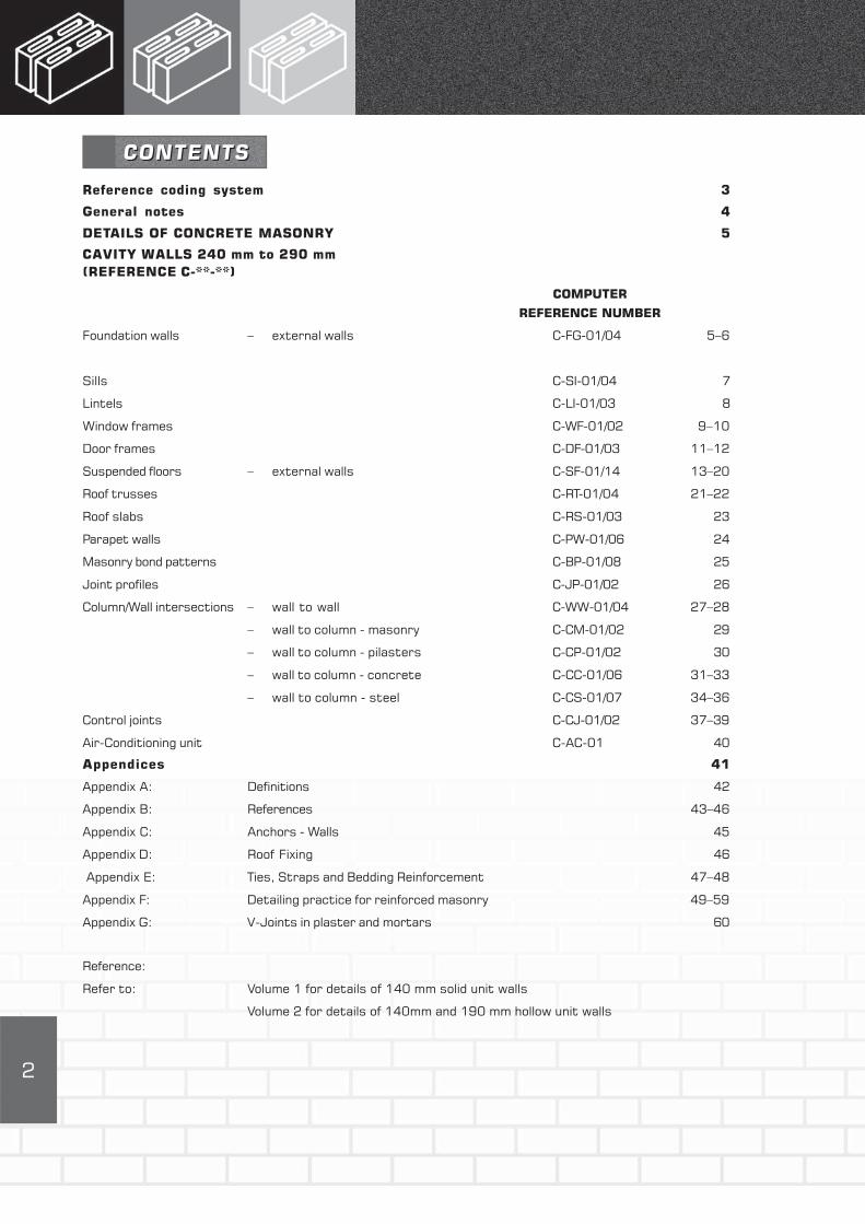
Reference coding system 3
General notes 4
DETAILS OF CONCRETE MASONRY 5
CAVITY WALLS 240 mm to 290 mm
(REFERENCE C-**-**)
COMPUTER
REFERENCE NUMBER
Foundation walls – external walls C-FG-01/04 5–6
Sills C-SI-01/04 7
Lintels C-LI-01/03 8
Window frames C-WF-01/02 9–10
Door frames C-DF-01/03 11–12
Suspended floors – external walls C-SF-01/14 13–20
Roof trusses C-RT-01/04 21–22
Roof slabs C-RS-01/03 23
Parapet walls C-PW-01/06 24
Masonry bond patterns C-BP-01/08 25
Joint profiles C-JP-01/02 26
Column/Wall intersections – wall to wall C-WW-01/04 27–28
– wall to column - masonry C-CM-01/02 29
– wall to column - pilasters C-CP-01/02 30
– wall to column - concrete C-CC-01/06 31–33
– wall to column - steel C-CS-01/07 34–36
Control joints C-CJ-01/02 37–39
Air-Conditioning unit C-AC-01 40
Appendices 41
Appendix A: Definitions 42
Appendix B: References 43–46
Appendix C: Anchors - Walls 45
Appendix D: Roof Fixing 46
Appendix E: Ties, Straps and Bedding Reinforcement 47–48
Appendix F: Detailing practice for reinforced masonry 49–59
Appendix G: V-Joints in plaster and mortars 60
Reference:
Refer to: Volume 1 for details of 140 mm solid unit walls
Volume 2 for details of 140mm and 190 mm hollow unit walls
CONTENTSCONTENTS

3
GUIDELINES ON THE DETAILING OF MASONRYSTRUCTURES REFERENCE CODING SYSTEMGUIDELINES ON THE DETAILING OF MASONRYSTRUCTURES REFERENCE CODING SYSTEM
DESCRIPTION OF WALL Computer
Reference
Number
SOLID UNIT SINGLE LEAF WALLS 140mm S-**-**
HOLLOW UNIT SINGLE LEAF WALLS 140 AND 190 mm H-**-**
CAVITY WALLS 240 TO 290 mm C-**-**
POSITION IN WALLS
AIRCONDITIONING UNITS C-AC-**
BEAM TO WALL C-BW-**
BONDING PATTERNS C-BP-**
CONTROL JOINTS C-CJ-**
DOOR FRAMES C-DF-**
FOUNDATIONS AND GROUND FLOOR SLAB C-FG-**
INTERSECTION WALL TO WALL C-WW-**
WALL TO COLUMN (CONCRETE) C-CC-**
WALL TO COLUMN (STEEL) C-CS-**
WALL TO COLUMN (MASONRY) C-CM-**
WALL TO COLUMN (PILASTERS) C-CP-**
JOINT PROFILES C-JP**
LINTELS C-LI-**
PARAPET WALLS INCLUDING COPING C-PW-**
REINFORCING C-RE-**
ROOF SLABS C-RS-**
ROOF TRUSSES C-RT-**
SERVICES C-SV-**
SILLS C-SI-**
SUSPENDED FLOOR C-SF-**
WINDOW FRAMES C-WF-**
NOTES C-**-NB
Notes:
The computer reference number is the file name under which the individual drawings are stored. The last
two digits (indicated with an asterix above) represent the numbering of drawing in that particular
category. Where the last two digits are replaced with the letter “NB”, this file contains notes which are
pertinent to the drawings in the particular category.

4
GENERAL NOTESGENERAL NOTES
Degree of fixity between elements and likely
movement.
Special finishes and specification requirements.
Workmanship quality
Design
Modular co-ordination of building elements work to
200mm module horizontally and 100mm vertically.
Details in these guidelines do not necessarily apply to
masonry structures over four storeys in height.
Unless otherwise stated, the details shown are based
on the “deemed to satisfy” clauses of SANS 10400
and the NHBRC Home Building Manual (HBM).
In SABS standard only strip foundations are covered,
but there may be a need for special foundations in
particular cases. Authoritative advice should be
obtained in this regard.
The information contained in this publication is
intended as a guide only. The Concrete Manufacturers
Association cannot be held responsible for its
interpretation and use.
Width of cavity walls
SANS 10400 The application of the National Building
Regulations details cavity walls of 90–50 to 90–100–
90 i.e. 230 to 290 mm cavity walls.
A 230 mm cavity wall is not modular. This means that
there is considerable cutting of units in the building of
these walls. However, if the cavity is increased to 60
mm with an overall width of 240 mm walls become
more buildable. At the edge of door and window
frames a 90 and a 140 mm unit can be used to close
the cavity. In structural 240 mm cavity walls the inner
structural leaf can be 140 and the outer non-
structural leaf 90 mm.
The preferred dimensions of a cavity wall are
90–110–90 i.e. 290 mm overall. This wall is
completely modular and can be built with minimum
cutting of units. Closing of cavity around windows,
doors, sills and lintels can be easily achieved using two
140 mm blocks or a 90 mm and 190 mm block.
Concrete masonry has wide applications in modern
industrial, commercial, educational and residential
buildings.
The main types of masonry walls dealt with in these
guidelines are: single leaf walls using solid units
(Vol 1), single leaf walls using hollow units (Vol 2) and
cavity walls (Vol 3).
The details shown in this publication are intended
merely as a guide. Each construction situation is
unique and there are many factors to be considered
before a detail is finalised – far too many for inclusion
here.
The purpose of good detailing is to assist in achieving
sound construction and a buildable structure that will
perform well in service.
The following factors must be taken into account when
detailing for concrete masonry structures:
Materials:
Concrete masonry units:
solid/hollow – dimensions
non-face/face – texture, colour and profile
properties and availability.
Mortar:
Class to be used plus materials. (Will mortar sand
result in high shrinkage of mortar and wall?)
Environmental conditions:
Environment:
Orientation
Likelihood of significant movement due to
temperature and moisture variations
Earth/Seismic movement
Service conditions:
Loading:
dead, imposed, wind, unexpected
Aggressive conditions:
corrosion
Type of structure
Unreinforced/reinforced/prestressed
Composite structure:
masonry/reinforced concrete
masonry/prestressed concrete
masonry/structural steel
masonry/timber and their interaction

5
FOUNDATION AND WALL DETAILS – EXTERNAL WALLS
C-FG-01See C-FG-NB
150
min
Wall tieevery 400mm
NGL
STRIP FOUNDATION
60–110cavity
600
Weepholes inperpendjoints at600mmmaximum
Concrete
floor slab
15 MPa concreteinfill of cavity tosupport DPC
C-FG-02See C-FG-NB
200
STRIP FOUNDATION
600
C-FG-03See C-FG-NB
Weepholes inperpend jointsat 600mmmaximum
150
min
NGL
Damproofsheeting
THICKENED SLAB
FOUNDATION
600
Damproofsheeting
FOUNDATION AND WALL DETAILS – EXTERNAL WALLS
Damproofsheeting
DPC
Concrete foundation
& floor slab
200
min
90 90
DPC
Variable
200
150
min
NGL
Variable
60–110cavity
90 90Weepholes inperpend jointsat 600mmmaximum
Concrete
floor slab
15 MPa concreteinfill of cavity toNGL level
Damproofsheeting
DPCDPC
Wall tieevery 400mm
60–110cavity
90 90
Wall tieevery 400mm
15 MPa concreteinfill of cavity tosupport DPC

6
THICKENED SLAB
FOUNDATION
600
150
min
NGL
Concrete foundation
& floor slab
Dampproofsheeting
200
Weepholes inperpend jointsat 600mmmaximum
DPC
FOUNDATION AND WALL DETAILS – EXTERNAL WALLS
C-FG-04See C-FG-NB
Note:
1. Thickened slab foundations may cause cracking with ground floor slab. Consider use of fabricreinforcement in slab to limit cracking, or construction joints at junction of floor slab andfoundation.
2. The bearing capacity and sensitivity to moisture changes of soil may be unsatisfactory with thickenedslab foundations.
3. Foundation dimensions based on SANS 10400. Refer to SANS 10161:1980 ‘The Design ofFoundations for Building’ for foundation sizes based on specific soil conditions.
4. Foundation material conditions will determine whether wall, concrete and steel columns share acommon foundation around the column foundation area. Estimates of likely settlement betweenwall and column will determine the need or otherwise for movement (control) joints in the wall.
5. Stepped DPC height may be over half height of block.
C-FG-NB
FOUNDATION AND WALL DETAILS – EXTERNAL WALLS
60–110cavity
90 90
Wall tieevery 400mm
15 MPa concreteinfill of cavity tosupport DPC
6. For internal walls refer to Volume 1 – 140mm Solid Unit Single Leaf Walls and Volume 2 – 140mmor 190mm Hollow Unit Single Leaf Walls.

7
190mm WIDE SILL BLOCK
– 290mm WALL
C-SI-01See C-SI-NB
C-SI-02See C-SI-NB
C-SI-NB
Note:
1. Clear water-repellent coating to be applied to masonry sillblock exposed surfaces.
WINDOW SILL DETAILSWINDOW SILL DETAILS
C-SI-03See C-SI-NB
C-SI-04See C-SI-NB
140mm WIDE SILL BLOCK
– 240mm WALL
110cavity
90 90
DPC
Sill
3mm fibrecementboard sheet
Wall tieevery 400mm
190 sill block 140 sill block
Sill
140 U block
60cavity
90 90
DPC
110cavity
90 90
DPC
3mm fibrecement sheet
Wall tieevery 400mm
140 sill block
140mm WIDE SILL BLOCK
– 290mm WALL PRECAST CONCRETE SILL
Precastconcrete sill
V-joint ifinside of wallplastered
DPC
Wall tieevery 400mm
Seal horizontaljoints betweensills andmasonry unit
110cavity
90 90

8
WINDOW LINTEL DETAILSWINDOW LINTEL DETAILS
LINTEL USING 190mm U-BEAM
C-LI-01See C-FG-NB Note 5
See C-LI-NB
C-LI-02See C-FG-NB Note 5
See C-LI-NB
C-LI-NB
Note:
1. Refer to CMA Design Guide and Technical Notes onLintels.
2. Lintel units manufactured in different lengthsUnit LengthsLintel sash block 190mmU-block 190/390mmRock face bond block 190/390mmFairface bond block 390mm
3. For rockface units use bond blocks or rock face unitssupported on angle. For smooth face use U- or sashlintel units.
C-LI-03See C-FG-NB Note 5
See C-LI-NB
LINTEL USING 190mm
BOND BLOCK BEAM
DPC onconcrete infill
Lintel U-beam(use 140mmblock for 240mmcavity wall)
Weepholes invertical jointevery 600mmmaximum
LINTEL USING 140 U-BEAM
110cavity
90 90
MS anglebolted tobeam
110cavity
90 90
Weepholes invertical jointevery 600mmmaximum
Bond block withcores filled withconcrete. Soffitconcrete requiressupport and finishing(use 140mm bondblock for 240mmcavity wall)
DPC onconcreteinfill
Lintel U-beam
DPC onconcreteinfill
Lintel U-beam(90 or 140mmwidth)
Weepholes invertical jointevery 600mmmaximum
60–110cavity
90 90
V-joint inplaster
LintelU-beam
Plaster

9
Lintelreinforcement
Lugs to frame
X X
FRONT ELEVATION SECTION
C-WF-01See C-SI-01/04
See C-LI-01/03
Over
all
win
do
w f
ram
e si
ze :
625,
825
, 10
25,1
425,
162
5
Lintel tosuit
Sill to suit
Wall ties
Overall window frame size :
625, 825, 1025, 1425, 1825
PLAN AT X – X
Butterfly wallties everysecond course
Sealant
WINDOW DETAILSWINDOW DETAILS
STEEL WINDOW FRAMES OF MODULAR DIMENSIONS
DPC
Butterfly wall ties everysecond course
DPC
Sill blocks
DPC
DPC
9090
60–
110
cavit
y

10
Lintelreinforcement
Lugs to frame
X X
FRONT ELEVATION SECTION
C-WF-02See C-SI-01/04
See C-LI-01/03
Over
all
win
do
w f
ram
e si
ze :
359,
654
, 94
9, 1
245,
154
0, 1
854
Lintel tosuit
Sill tosuit
Wall ties
Overall window frame size :
533, 1022, 1511, 2000, 2489
PLAN AT X – X
Sealant
WINDOW DETAILSWINDOW DETAILS
STEEL WINDOW FRAMES OF NON-MODULAR DIMENSIONS
DPC
DPC
Sill blocks
DPC
DPC
Cut unitunder sill tofit modularcoursing
Adjust jointwidthsor cut unitsto fit

11
Lugs to frame
X X
Door size 813 x 2032
Finished floor level
ELEVATIONJoint widths adjusted tofix door frame inmasonry
SECTION
21 m
od
ule
s =
210
0
2089
3520
3222
9 modules = 900
813
883
35 35
PLAN AT X – X
STEEL DOOR FRAME TO TAKE 813 x 2032 DOOR
C-DF-01
DOOR FRAME DETAILS – STEEL FRAMESDOOR FRAME DETAILS – STEEL FRAMES
Lintel block
Butterfly wall tiesevery second course
Butterfly wallties everysecond course
9090
60–
110
cavit
y
DPC DPC

12
SECTION
21 m
od
ule
s =
210
0
2107
5320
3222
Lugs to frame
Door size 813 x 2032
Finished floor level
ELEVATIONJoint widths adjusted to fixdoor frame in masonry
9 modules = 900
813
919
53 53
PLAN AT Y – Y
TIMBER DOOR FRAME TO TAKE 813 x 2032 DOOR
Y Y
C-DF-02
DOOR FRAME DETAILS – TIMBER FRAMESDOOR FRAME DETAILS – TIMBER FRAMES
Frame tied to wall
Lintel block
Butterfly wall tiesevery second course
Butterfly wallties everysecond course
9090
60–
110
cavit
y
DPC DPC

13
Many factors influence the detail to be used at the
junction of suspended concrete floors. Consideration
should be given to the following:
STRUCTURAL ASPECTS
Is wall below slab structural or non-structural?
Is wall above slab structural or non-structural?
Is allowance to be made for vertical differential
movement between structural and non-structural
leaves of wall (important in cavity walls)?
Is allowance to be made between top of supporting
structural wall and slab for horizontal movement i.e.
sliding? Or should there be fixity between wall and slab?
(Note: This affects both design of wall and slab)
INDEX TO SUSPENDED FLOORS ON EXTERNAL WALLSINDEX TO SUSPENDED FLOORS ON EXTERNAL WALLS
DETAILING ASPECTS
Is slab of modular thickness (100, 200, 300,
400mm) or non-modular thickness? If slab
thickness less than modular use concrete fillets
above slab to restore modular thickness. If slab
thickness greater than modular use cut blocks
above slab to restore modular coursing. Does
suspended slab close cavity or not?
Is dampproofing required and if so DPC profile and
position or weepholes?
Space does not permit all alternatives to be
detailed and drawn. The index gives references to
typical sketches.
WALL UNDERSLABWALL ABOVESLABWALL/SLABFIXITY
SLA
B T
HIC
KN
ES
S
LE
SS
T
HA
N M
OD
ULA
RM
OD
UL
AR
GR
EA
TE
R TH
AN
M
OD
ULA
R
CA
VIT
YC
AV
ITY
CA
VIT
Y
OP
EN
CL
OS
ED
OP
EN
CL
OS
ED
OP
EN
CL
OS
ED
STRUCTURAL NON-STRUCTURAL
STRUCTURAL NON-STRUCTURAL
YES NO
C-SF-11
C-SF-12
C-SF-10
C-SF-09
C-SF-02
C-SF-08
C-SF-07
C-SF-05
C-SF-03
C-SF-01
C-SF-06
C-SF-04
C-SF-14
C-SF-13

14
Wall tieevery 400mm
Slip joint.See note 2
Concrete slab ofmodular thickness
Mortar fillet
Topping if required
WALL: INNER LEAF -STRUCTURAL BELOW SLAB
-NON STRUCTURAL ABOVE SLAB
OUTER LEAF NON-STRUCTURAL
SLAB: MODULAR THICKNESS
CAVITY: OPEN
C-SF-01See C-SF-NB
Topping if required
Concrete slab ofmodular thickness
C-SF-02See C-SF-NB
SUSPENDED FLOORS ON EXTERNAL WALLSSUSPENDED FLOORS ON EXTERNAL WALLS
WALL: INNER LEAF STRUCTURAL
OUTER LEAF NON-STRUCTURAL
SLAB: MODULAR THICKNESS
CAVITY: OPEN
60–110cavity
90 90
90 140
Wall tieevery 400mm.See note 4
Wall tieevery 400mm
Slip joint.See note 2
60cavity
90 140
90 140
Wall tieevery 400mm.See note 4

15
C-SF-03See C-SF-NB
SUSPENDED FLOORS ON EXTERNAL WALLSSUSPENDED FLOORS ON EXTERNAL WALLS
WALL: INNER LEAF -STRUCTURAL BELOW SLAB
-NON STRUCTURAL ABOVE SLAB
OUTER LEAF NON-STRUCTURAL
SLAB: MODULAR THICKNESS
CAVITY: CLOSED
Wall tieevery 400mm.See note 4
Slip joint.See note 2
Concrete slab ofmodular thickness
Bond breaker between slaband outer leaf. See note 7
Topping if required
60–110cavity
90 90
90 140
Wall tieevery 400mm
Weepholes inperpend jointsat 600mmmaximum
Mortar infill of cavity
DPC
6mm bar cast inblock below withprojecting leg intoblock above tohold in position
Wall tieevery 400mm.See note 4
Slip joint.See note 2
Concrete slab of less thanmodular thickness
15 MPa concrete infill
Topping if required
WALL: INNER LEAF -STRUCTURAL BELOW SLAB
-NON STRUCTURAL ABOVE SLAB
OUTER LEAF NON-STRUCTURAL
SLAB: < MODULAR THICKNESS
CAVITY: OPEN
C-SF-04See C-SF-NB
60–110cavity
90 90
90 140
Wall tieevery 400mm

16
SUSPENDED FLOORS ON EXTERNAL WALLSSUSPENDED FLOORS ON EXTERNAL WALLS
Topping if required
Concrete slab of greaterthan modular thickness
C-SF-05See C-SF-NB
WALL: INNER LEAF -STRUCTURAL BELOW SLAB
-NON STRUCTURAL ABOVE SLAB
OUTER LEAF NON-STRUCTURAL
SLAB: > MODULAR THICKNESS
CAVITY: OPEN
Wall tieevery 400mm
Slip joint.See note 2
60–110cavity
90 90
90 140
Wall tieevery 400mm.See note 4
Mortar infill
Block cut to fit
C-SF-06See C-SF-NB
WALL: INNER LEAF -STRUCTURAL BELOW SLAB
-NON STRUCTURAL ABOVE SLAB
OUTER LEAF NON-STRUCTURAL
SLAB: < MODULAR THICKNESS
CAVITY: CLOSED
Wall tieevery 400mm.See note 4
Slip joint.See note 2
Concrete slab of lessthan modular thickness
Bond breaker between slaband outer leaf. See note 7
Topping if required
60–110cavity
90 90
90 140
Wall tieevery 400mm
Weepholes inperpend jointsat 600mmmaximum
Mortar infill of cavity
Stepped DPC
Drip groove
15 MPa concrete infill

17
SUSPENDED FLOORS ON EXTERNAL WALLSSUSPENDED FLOORS ON EXTERNAL WALLS
C-SF-07See C-SF-NB
WALL: INNER LEAF -STRUCTURAL BELOW SLAB
-NON STRUCTURAL ABOVE SLAB
OUTER LEAF NON-STRUCTURAL
SLAB: > MODULAR THICKNESS
CAVITY: CLOSED
Wall tie every 400mm.See note 4
Slip joint.See note 2
Concrete slab of greaterthan modular thickness
Bond breaker between slaband outer leaf. See note 7
Topping if required
60–110cavity
90 90
90 140
Wall tieevery 400mm
Weepholes inperpend jointsat 600mmmaximum
Drip groove
Block cut to fit
Stepped DPC supportedon mortar infill
Wall tieevery 400mm.See note 4
Slip joint.See note 2
Concrete slab of lessthan modular thickness
15 MPa concrete infill
Topping if required
WALL: INNER LEAF STRUCTURAL
OUTER LEAF NON-STRUCTURAL
SLAB: < MODULAR THICKNESS
CAVITY: OPEN
C-SF-08See C-SF-NB
60cavity
90 140
90 140
Wall tieevery 400mm

18
SUSPENDED FLOORS ON EXTERNAL WALLSSUSPENDED FLOORS ON EXTERNAL WALLS
Topping if required
Concrete slab of greaterthan modular thickness
C-SF-09See C-SF-NB
WALL: INNER LEAF STRUCTURAL
OUTER LEAF NON-STRUCTURAL
SLAB: > MODULAR THICKNESS
CAVITY: OPEN
Wall tieevery 400mm
Slip joint.See note 2
90 140
Wall tieevery 400mm.See note 4
Block cut to fit
60cavity
90 140
C-SF-10See C-SF-NB
WALL: INNER LEAF STRUCTURAL
OUTER LEAF NON-STRUCTURAL
SLAB: < MODULAR THICKNESS
CAVITY: OPEN
WALL/SLAB: FIXITY
Wall tie every 400mm.See note 4
Projecting bar fromU-beam cast into slab
Concrete slab of lessthan modular thickness
Topping if required
90 140
Wall tieevery 400mm
60cavity
90 140
15 MPa concrete infill

19
SUSPENDED FLOORS ON INTERNAL WALLSSUSPENDED FLOORS ON INTERNAL WALLS
C-SF-11See C-SF-NB
WALL: INNER LEAF STRUCTURAL
OUTER LEAF NON-STRUCTURAL
SLAB: > MODULAR THICKNESS
CAVITY: CLOSED
WALL/SLAB: FIXITY
Wall tie every 400mm.See note 4
Topping if required
90 140
Wall tieevery 400mm
Block cut to fit
60cavity
90 140
Projecting bar fromU-beam cast into slab
Concrete slab of greaterthan modular thickness
C-SF-12See C-SF-NB
Wall tieevery 400mm
Projecting bar fromU-beam cast into slab
Concrete slab ofmodular thickness
Stepped DPC supportedon 15 MPa concrete infill
Topping if required
60cavity
90 140
90 140
Wall tieevery 400mm.See note 4Weepholes in
perpend jointsat 600mmmaximum
Concrete infill
WALL: INNER LEAF STRUCTURAL
OUTER LEAF NON-STRUCTURAL
SLAB: MODULAR THICKNESS
CAVITY: CLOSED
WALL/SLAB: FIXITY

20
C-SF-13See C-SF-NB
C-SF-14See C-SF-NB
SUSPENDED FLOORS ON EXTERNAL WALLSSUSPENDED FLOORS ON EXTERNAL WALLS
Wall tie every400mm
Concrete slab ofmodular thickness
90 90
Wall tie every400mm.See note 4
60–110cavity
90 90
10mm gap min.
WALL: INNER LEAF
NON-STRUCTURAL
OUTER LEAF
NON-STRUCTURAL
SLAB: MODULAR THICKNESS
CAVITY: OPEN
Wall tieevery 400mm
Concrete slab ofmodular thickness
Stepped DPC supportedon 15 MPa concrete infill
Topping if required
Wall tieevery 400mm.See note 4
Weepholes inperpend jointsat 600mmmaximum
MS angle fixedto slab to supportmasonry leaf
WALL: INNER LEAF
NON-STRUCTURAL
OUTER LEAF
NON-STRUCTURAL
SLAB: MODULAR THICKNESS
CAVITY: CLOSED
90 90
60–110cavity
90 90
M.S. angles fixed toslab soffit to providelateral support
10mm gap min.Joint belowsealed topreventmoisturepenetration
Note:
C-SF-NB
1. Stepped DPC to rest on mortar/concrete infill.2. If floor slab exceeds 6m spanning on to wall and
large movements are expected consider a slip jointon top of wall, such as two layers of DPC orgalvanised sheets or kilcher bearings or similar.Structural stability and robustness may precludeuse of slip joint.If designer assumes wall laterally restrained by slabthen slip joint not advisable.
3. 90mm minimum bearing under slab.4. Wall ties to be built in as shown at horizontal
spacing not exceeding 400mm.5. Generally 90mm thick walls are non-structural.
140mm thick wall can be used in place of 90mmthick internal leaf to support slab.
6. Internal structural walls may be 90mm thick withpiers, or 140mm or 190mm thick.
7. Use bond breaker (plastic sheet, bitumen, paintetc.) between outer leaf and beam/slab at (point ofcontact) where differential movement is expected.
8. Stepped DPC height may be over full or halfheight of block.

21
ROOF TRUSS FIXING TO
CAVITY WALL
Galvanised steel wire orhoop iron strapanchored in cavity, filledwith 15 MPa concrete,fixed to roof truss
C-RT-01See App D
ROOF TRUSS FIXING TO CAVITY
WALL, OVER OPENING
Galvanised steel wire or hoop ironstrap wrapped around reinforcingbar and cast into U-beam, fixed toroof truss. U-beam anchored to wall.See C-RT-03
Wall tiesevery 400mm
C-RT-02See App D
See C-RT-03
ROOF TRUSS FIXING TO WALLROOF TRUSS FIXING TO WALL
3mm fibre cementsheet to supportconcrete infill
90 90
60–110cavity
3mm fibre cementsheet to supportconcrete infill90 90
60–110cavity

22
ROOF TRUSS FIXING TO WALLROOF TRUSS FIXING TO WALL
ANCHORING OF BEAM OVER OPENINGS
C-RT-03See App D
ROOF TRUSS FIXING CAVITY WALL
C-RT-04See App D
Ties projecting from lintelto anchor roof truss
Opening
Lintel
Anchors to tiebeam into wallwhere required
3mm fibrecement sheet
90 90
60–110cavity
Galvanised steelwire or hoop ironstrap wrappedaround reinforcingbar and cast intoU-beam fixed toroof truss
23
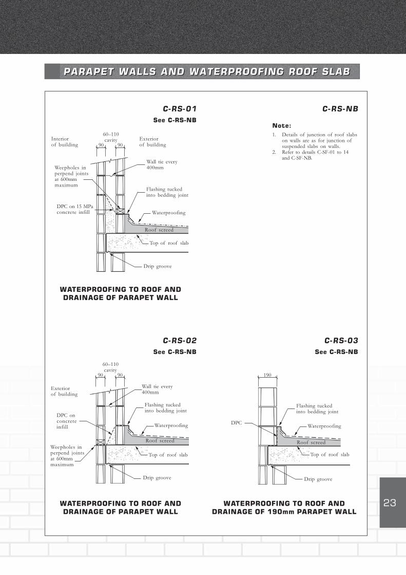
PARAPET WALLS AND WATERPROOFING ROOF SLABPARAPET WALLS AND WATERPROOFING ROOF SLAB
C-RS-01See C-RS-NB
Drip groove
Roof screed
Flashing tuckedinto bedding joint
Waterproofing
60–110cavity
90
Wall tie every400mmWeepholes in
perpend jointsat 600mmmaximum
DPC on 15 MPaconcrete infill
WATERPROOFING TO ROOF AND
DRAINAGE OF PARAPET WALL
90
Top of roof slab
C-RS-NB
Note:
1. Details of junction of roof slabson walls are as for junction ofsuspended slabs on walls.
2. Refer to details C-SF-01 to 14and C-SF-NB.
C-RS-02See C-RS-NB
Drip groove
Roof screed
Flashing tuckedinto bedding joint
Waterproofing
60–110cavity
90
Wall tie every400mm
Weepholes inperpend jointsat 600mmmaximum
DPC onconcreteinfill
WATERPROOFING TO ROOF AND
DRAINAGE OF PARAPET WALL
90
Top of roof slab
Interiorof building
Exteriorof building
Exteriorof building
C-RS-03See C-RS-NB
Drip groove
Roof screed
Flashing tuckedinto bedding joint
Waterproofing
190
DPC
WATERPROOFING TO ROOF AND
DRAINAGE OF 190mm PARAPET WALL
Top of roof slab
24
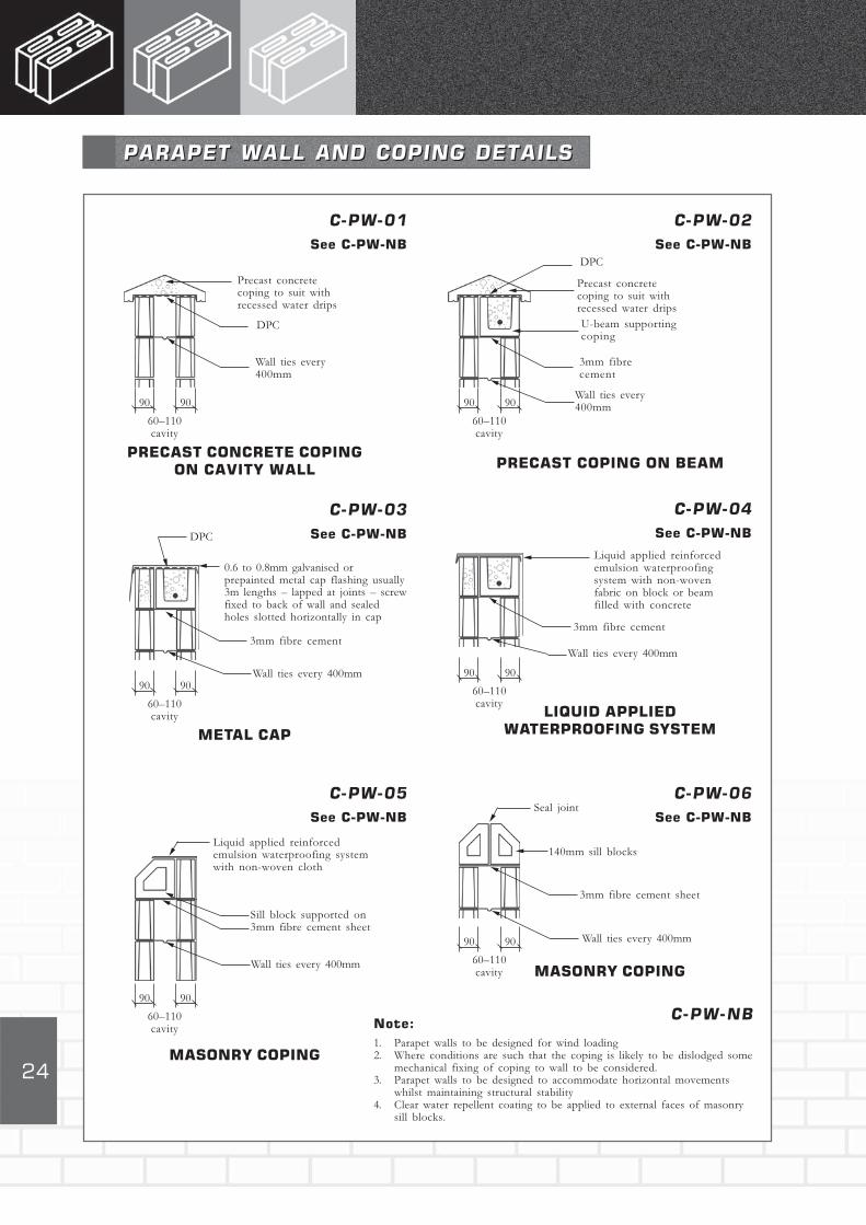
C-PW-01See C-PW-NB
C-PW-02See C-PW-NB
C-PW-03See C-PW-NB
C-PW-04See C-PW-NB
C-PW-05See C-PW-NB
C-PW-06See C-PW-NB
PRECAST CONCRETE COPING
ON CAVITY WALL PRECAST COPING ON BEAM
METAL CAP
LIQUID APPLIED
WATERPROOFING SYSTEM
MASONRY COPING
MASONRY COPING
DPC
Precast concretecoping to suit withrecessed water drips
Wall ties every400mm
DPC
Precast concretecoping to suit withrecessed water drips
Wall ties every400mm
U-beam supportingcoping
3mm fibrecement
90 90
60–110cavity
90 90
60–110cavity
0.6 to 0.8mm galvanised orprepainted metal cap flashing usually3m lengths – lapped at joints – screwfixed to back of wall and sealedholes slotted horizontally in cap
Wall ties every 400mm
3mm fibre cement
90 90
60–110cavity
90 90
60–110cavity
3mm fibre cement
90 90
60–110cavity
Liquid applied reinforcedemulsion waterproofing systemwith non-woven cloth
Wall ties every 400mm
Sill block supported on3mm fibre cement sheet
Wall ties every 400mm
3mm fibre cement sheet
140mm sill blocks
Seal joint
C-PW-NBNote:
1. Parapet walls to be designed for wind loading2. Where conditions are such that the coping is likely to be dislodged some
mechanical fixing of coping to wall to be considered.3. Parapet walls to be designed to accommodate horizontal movements
whilst maintaining structural stability4. Clear water repellent coating to be applied to external faces of masonry
sill blocks.
PARAPET WALL AND COPING DETAILSPARAPET WALL AND COPING DETAILS
90 90
60–110cavity
Liquid applied reinforcedemulsion waterproofingsystem with non-wovenfabric on block or beamfilled with concrete
Wall ties every 400mm
DPC
25
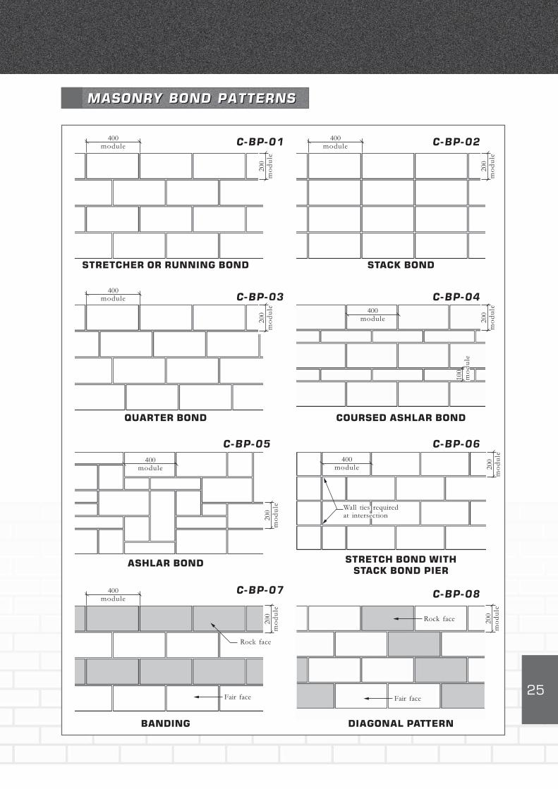
C-BP-01 C-BP-02
MASONRY BOND PATTERNSMASONRY BOND PATTERNS
C-BP-03 C-BP-04
C-BP-05 C-BP-06
C-BP-07 C-BP-08
STRETCHER OR RUNNING BOND STACK BOND
QUARTER BOND COURSED ASHLAR BOND
ASHLAR BOND STRETCH BOND WITH
STACK BOND PIER
BANDING DIAGONAL PATTERN
400module
200
mo
du
le
400module
200
mo
du
le
400module
200
mo
du
le 400module 20
0m
od
ule
100
mo
du
le400
module
200
mo
du
le
400module 20
0m
od
ule
Wall ties requiredat intersection
Rock face
Fair face Fair face
Rock face200
mo
du
le
200
mo
du
le
400module
26
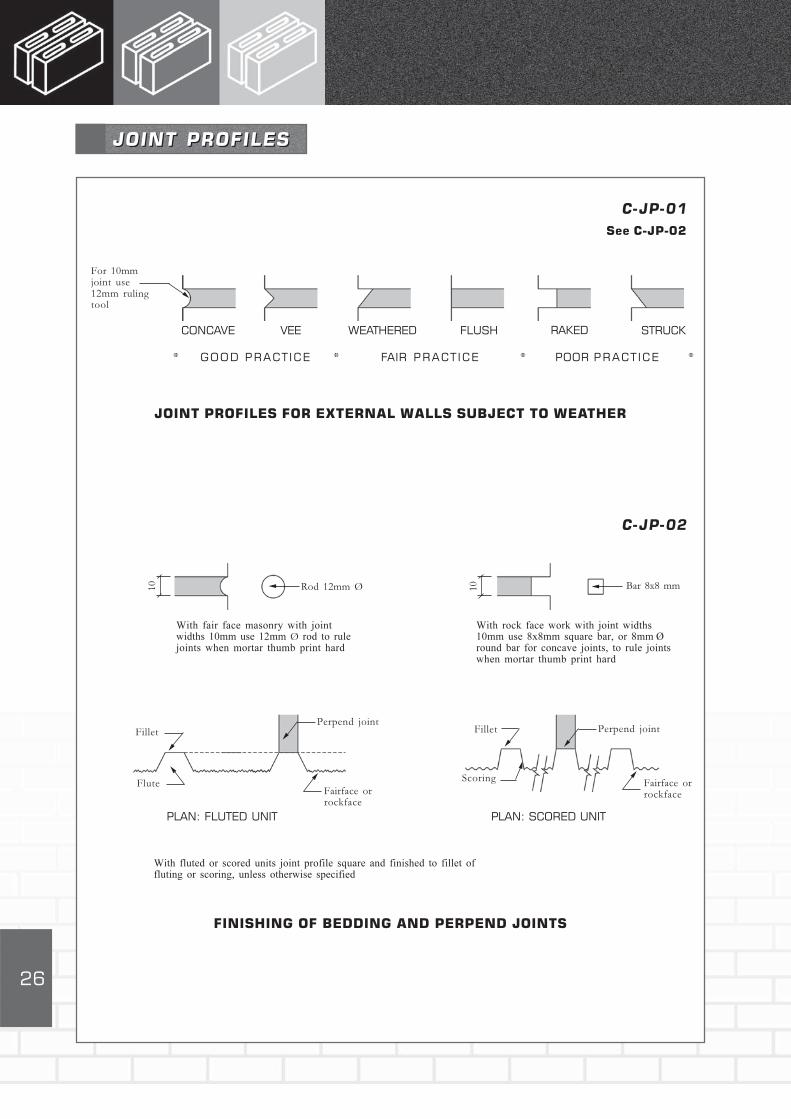
JOINT PROFILESJOINT PROFILES
C-JP-01See C-JP-02
For 10mmjoint use12mm rulingtool
CONCAVE VEE WEATHERED FLUSH RAKED STRUCK
GOOD PRACT ICE FAIR PRACT ICE POOR PRACT ICE* * * *
JOINT PROFILES FOR EXTERNAL WALLS SUBJECT TO WEATHER
10 Rod 12mm Ø 10
With fair face masonry with jointwidths 10mm use 12mm Ø rod to rulejoints when mortar thumb print hard
With rock face work with joint widths10mm use 8x8mm square bar, or 8mm Øround bar for concave joints, to rule jointswhen mortar thumb print hard
Perpend jointFillet
FluteFairface orrockface
Perpend jointFillet
Scoring Fairface orrockface
PLAN: FLUTED UNIT PLAN: SCORED UNIT
With fluted or scored units joint profile square and finished to fillet offluting or scoring, unless otherwise specified
FINISHING OF BEDDING AND PERPEND JOINTS
C-JP-02
Bar 8x8 mm
27
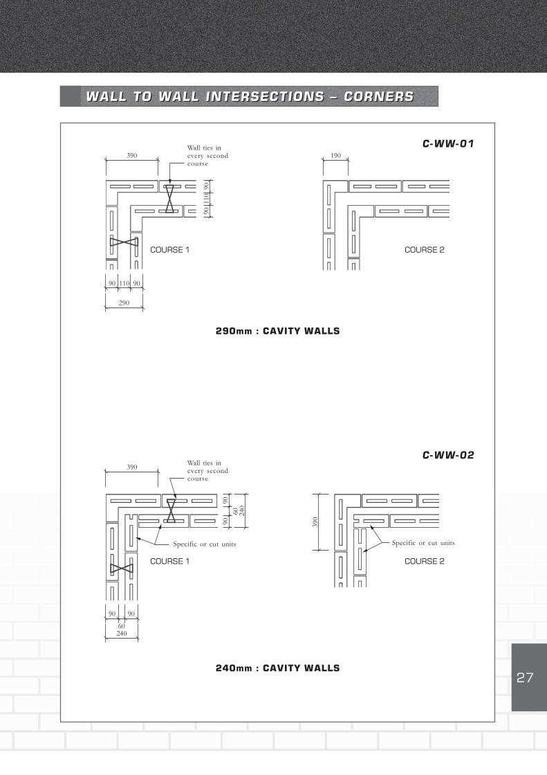
390
COURSE 1
190
COURSE 2
290mm : CAVITY WALLS
C-WW-01
240mm : CAVITY WALLS
90
390
COURSE 1 COURSE 2
C-WW-02
90
WALL TO WALL INTERSECTIONS – CORNERSWALL TO WALL INTERSECTIONS – CORNERS
Wall ties inevery secondcourse
110
90
Wall ties inevery secondcourse
90
60
90
Specific or cut units
90
60240
Specific or cut units
390
90 90
290
110
240

28
COURSE 1
BONDING OF INTERNAL LEAF OF CAVITY WALL
C-WW-04
COURSE 2
WALL TO WALL INTERSECTIONSWALL TO WALL INTERSECTIONS
90
BONDING OF INTERNAL LEAF OF CAVITY WALL
COURSE 1 COURSE 2
C-WW-03
Wall ties in everysecond course
Cores filled solidwith 15 MPa concrete
10x30 mesh 0.6mm thick x 1.0mmwide lathing 60mm wide x 350mmlong every second course
Cores of unitsfilled with15 MPa concrete
10x30 mesh 0.6mm thick x 1.0mmwide lathing 60mm wide x 250mmlong every second course
390
9090
290
110
9090
240
60
29
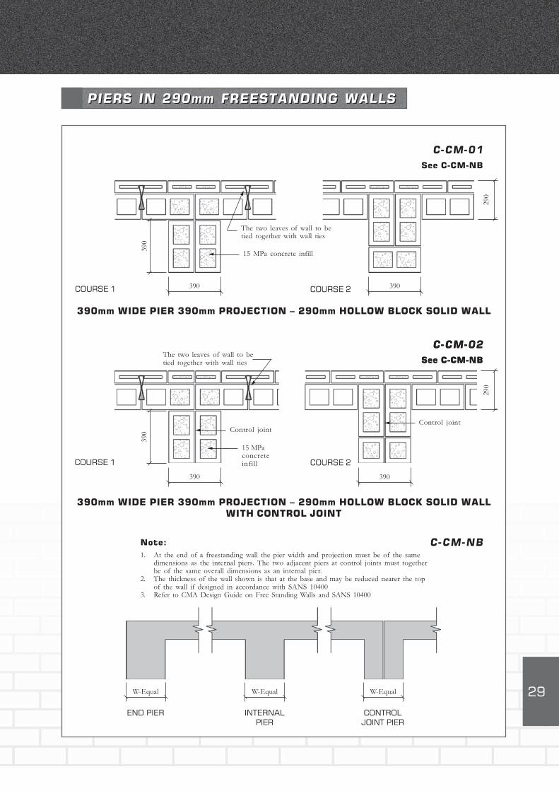
COURSE 1
The two leaves of wall to betied together with wall ties
390mm WIDE PIER 390mm PROJECTION – 290mm HOLLOW BLOCK SOLID WALL
COURSE 2
C-CM-01See C-CM-NB
390
390
COURSE 1 COURSE 2
C-CM-02See C-CM-NB
390mm WIDE PIER 390mm PROJECTION – 290mm HOLLOW BLOCK SOLID WALL
WITH CONTROL JOINT
PIERS IN 290mm FREESTANDING WALLSPIERS IN 290mm FREESTANDING WALLS
15 MPa concrete infill
390
290
The two leaves of wall to betied together with wall ties
Control joint
15 MPaconcreteinfill
390
39029
0
END PIER
Control joint
INTERNALPIER
CONTROLJOINT PIER
W-Equal
390
W-Equal W-Equal
C-CM-02See C-CM-NB
C-CM-NBNote:
1. At the end of a freestanding wall the pier width and projection must be of the samedimensions as the internal piers. The two adjacent piers at control joints must togetherbe of the same overall dimensions as an internal pier.
2. The thickness of the wall shown is that at the base and may be reduced nearer the topof the wall if designed in accordance with SANS 10400
3. Refer to CMA Design Guide on Free Standing Walls and SANS 10400
30
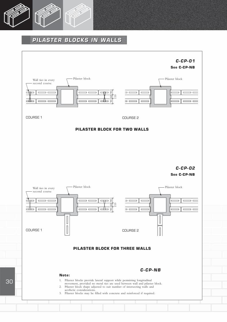
C-CP-01See C-CP-NB
PILASTER BLOCK FOR TWO WALLS
C-CP-02See C-CP-NB
PILASTER BLOCK FOR THREE WALLS
COURSE 1
Note:
1. Pilaster blocks provide lateral support while permitting longitudinalmovement, provided no metal ties are used between wall and pilaster block.
2. Pilaster block shape adjusted to suit number of intersecting walls andaesthetic considerations.
3. Pilaster blocks may be filled with concrete and reinforced if required.
C-CP-NB
PILASTER BLOCKS IN WALLSPILASTER BLOCKS IN WALLS
COURSE 2
COURSE 1 COURSE 2
Wall ties in everysecond course
9090
110
Pilaster block
60
Pilaster block
Wall ties in everysecond course
9090
110
Pilaster block
60
Pilaster block
31
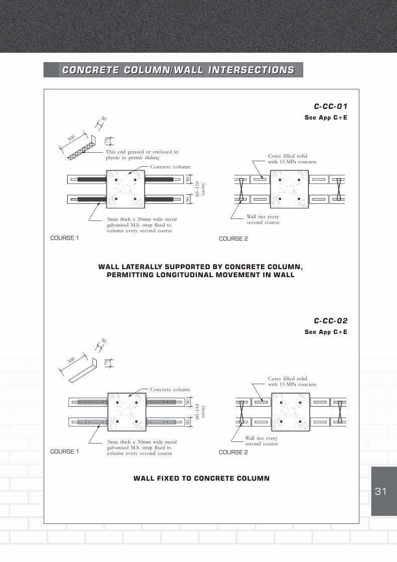
WALL LATERALLY SUPPORTED BY CONCRETE COLUMN,
PERMITTING LONGITUDINAL MOVEMENT IN WALL
C-CC-01See App C+E
C-CC-02See App C+E
WALL FIXED TO CONCRETE COLUMN
CONCRETE COLUMN/WALL INTERSECTIONSCONCRETE COLUMN/WALL INTERSECTIONS
COURSE 1 COURSE 2
COURSE 1 COURSE 2
75300
30
75300
30
This end greased or enclosed inplastic to permit sliding
Concrete column
3mm thick x 30mm wide metalgalvanised M.S. strap fixed tocolumn every second course
Wall ties everysecond course
Cores filled solidwith 15 MPa concrete
9090
60–
110
cavit
y
Concrete column
3mm thick x 30mm wide metalgalvanised M.S. strap fixed tocolumn every second course
Wall ties everysecond course
Cores filled solidwith 15 MPa concrete
9090
60–
110
cavit
y

32
CONCRETE COLUMN/WALL INTERSECTIONSCONCRETE COLUMN/WALL INTERSECTIONS
WALL LATERALLY SUPPORTED BY CONCRETE COLUMN
C-CC-03See App C
C-CC-04See App C
CONCRETE COLUMN WITH ROCKFACE UNITS
COURSE 1 COURSE 2
COURSE 1 COURSE 2
Concrete column
Metal slot castinto column totake dovetailgalvanised M.S.tie-every secondcourse
Cores filled solidwith 15 MPa concrete
9090
60–
110
cavit
y
Wall tieseverysecondcourse
Wall ties everysecond course
Wall ties everysecond course
Concrete column
9090
60–
110
cavit
y

33
CONCRETE COLUMN/WALL INTERSECTIONSCONCRETE COLUMN/WALL INTERSECTIONS
CONCRETE COLUMN BOXED-IN WITH ROCKFACE UNITS
C-CC-05See App C
C-CC-06See App C
CONCRETE COLUMN BOXED-IN WITH ROCKFACE UNITS
COURSE 1 COURSE 2
Concrete column
COURSE 1 COURSE 2
Wall ties everysecond course
9090
60–
110
cavit
y
Core filledwith concreteor mortar
10x30mm mesh 0.6mmthick x 1.0mm wide lathing60mm wide x 250mm longevery second course
Wall ties everysecond course
9090
60–
110
cavit
y
Core filledwith concreteor mortar
10x30mm mesh 0.6mmthick x 1.0mm wide lathing60mm wide x 250mm longevery second course

34
STEEL COLUMN/WALL INTERSECTIONSSTEEL COLUMN/WALL INTERSECTIONS
C-CS-01See App C
C-CS-02
C-CS-03See App C
WALL LATERALLY SUPPORTED BY STEEL COLUMN
WITH CONTROL JOINTS
WALL LATERALLY SUPPORTED BY STEEL COLUMN
WALL BUTTING AGAINST STEEL COLUMN
9090
60–
110
cavit
y
COURSE 1 COURSE 2
COURSE 1 COURSE 2
COURSE 1 COURSE 2
Steel column
Ties in everysecond course
Bar welded to column
Cores filled with15 MPa concrete
Wall ties everysecond course
Wall ties everysecond course
Steel column
L-shaped units
9090
60–
110
cavit
y
Steel column
9090
60–
110
cavit
y
Controljoint
Wall tieseverysecondcourse
Coresfilled with15 MPaconcrete
Control jointFor detail of tie see C-CS-01ties in every second course
Controljoint
30mm wide x 3mmthick 600mm longgalvanisedM.S. strap greasedone side

35
STEEL COLUMN/WALL INTERSECTIONSSTEEL COLUMN/WALL INTERSECTIONS
STEEL COLUMN BOXED IN WITH CONTROL JOINT
C-CS-04
C-CS-05
STEEL COLUMN BUILT IN, PROVIDING LATERAL
SUPPORT FOR WALL
COURSE 1 COURSE 2
COURSE 1 COURSE 2
590
390
Controljoint
Controljoint
Controljoint
Wall ties everysecond course
9090
60–
110
cavit
y
Controljoint
Controljoint
Controljoint
590
290
Wall ties in everysecond course
Cores filled withconcrete or mortar
For detail of tiesee C-CS-01
Cores filled with15 MPa concrete

36
STEEL COLUMN/WALL INTERSECTIONSSTEEL COLUMN/WALL INTERSECTIONS
STEEL COLUMN BOXED IN WITH ROCKFACE UNITS
C-CS-06
C-CS-07
STEEL COLUMN BOXED IN WITH ROCKFACE UNITS
COURSE 1 COURSE 2
COURSE 1 COURSE 2
9090
60–
110
cavit
y
Wall ties in everysecond course
Steel column
Rockface Rockface
Steel column
9090
60–
110
cavit
y
590
390
10x30mm mesh 0.6mm thickx 1.0mm wide lathing 60mmwide x 250mm long everysecond course
Wall ties everysecond course
Coresfilledwith15 MPaconcrete

37
C-CJ-01See C-CJ-NB 1–4
BUTT CONTROL JOINT – PLAIN
CONTROL JOINTS IN WALLS
C-CJ-02See C-CJ-NB 1–4
BUTT CONTROL JOINT WITH STRAP TO GIVE LATERAL SUPPORT
Wall ties in everysecond course
9090
60–
110
cavit
y
Control joint L-shaped units Control joint L-shaped units
COURSE 1 COURSE 2
Wall ties in everysecond course
Control joint L-shaped units
Cores filled with15 MPa concrete
COURSE 1 COURSE 2
600x30x3mm galvanised M.S. strapgreased one side placed inbedding joint
Control joint L-shaped units
CONTROL JOINTS IN WALLSCONTROL JOINTS IN WALLS
38
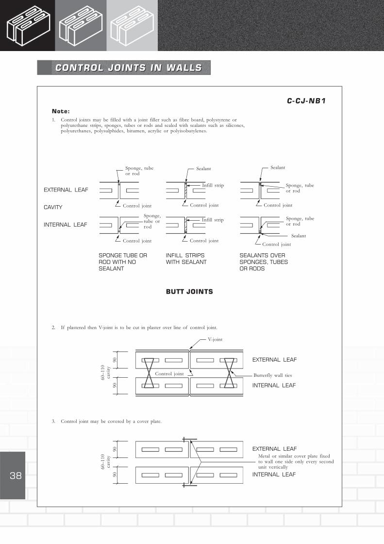
C-CJ-NB1Note:
1. Control joints may be filled with a joint filler such as fibre board, polystyrene orpolyurethane strips, sponges, tubes or rods and sealed with sealants such as silicones,polyurethanes, polysulphides, bitumen, acrylic or polyisobutylenes.
CONTROL JOINTS IN WALLSCONTROL JOINTS IN WALLS
Sponge, tubeor rod
BUTT JOINTS
EXTERNAL LEAF
CAVITY
INTERNAL LEAF
Sealant
Infill strip
Control jointControl joint Control joint
Sponge, tubeor rod
Sealant
Control jointControl jointControl joint
Sponge,tube orrod
Infill strip Sponge, tubeor rod
Sealant
SPONGE TUBE ORROD WITH NOSEALANT
INFILL STRIPSWITH SEALANT
SEALANTS OVERSPONGES, TUBESOR RODS
2. If plastered then V-joint is to be cut in plaster over line of control joint.
3. Control joint may be covered by a cover plate.
9090
60–
110
cavit
y
Control joint
EXTERNAL LEAF
INTERNAL LEAF
Butterfly wall ties
V-joint
9090
60–
110
cavit
y
EXTERNAL LEAF
INTERNAL LEAF
Metal or similar cover plate fixedto wall one side only every secondunit vertically

39
SECTION ELEVATION
C-CJ-NB2Wallplate level
ELEVATION OF WALL SHOWING CONTROL JOINT POSITIONS
BETWEEN OPENINGS, HORIZONTAL & VERTICAL REINFORCEMENT
CJ CJ CJ
BR BR BR BR BR BR
BR BR CJ
VR VR
DPC level
CJ = Control jointBR = Bedding reinforcement,
bond or U-beamVR = Vertical reinforcement
in cores
SECTION ELEVATION
C-CJ-NB3Wallplate level
ELEVATION OF WALL SHOWING CONTROL JOINT POSITIONS AT
EDGE OF OPENINGS, HORIZONTAL & VERTICAL REINFORCEMENT
CJ CJ CJ
BR BRBR BR
BR BR
VR
VR
DPC level
CJ = Control jointBR = Bedding reinforcement,
bond or U-beamVR = Vertical reinforcement
in cores
CJ CJ
BR BR
CJ
CJ CJ
BOND
C-CJ-NB4
PLAN OF WALL SHOWING CONTROL JOINT POSITIONS
U-BEAM BLOCK
BEDDING REINFORCEMENT
1m to 3m
CJ CJ
CJ
Joint spacing
Note:
Control joint spacing not toexceed recommendedmaximum, i.e. for unreinforcedwalls 6m, or twice the height ofthe wall.For reinforced walls 18m.Every course reinforced.For detailed informationrefer to CMA Masonry Manualand SANS 10145 ConcreteMasonry Construction
CONTROL JOINTS IN WALLS, LOCATIONSCONTROL JOINTS IN WALLS, LOCATIONS
CJ

40
C-AC-01
Grille/screen blocks
Air conditioning unit insteel sheet frame slid intoopening in wall
90
AIR CONDITIONING UNIT
INSTALLATION
Sill
DPC with weepholesevery 600mm
DETAILS OF AIRCONDITIONING UNIT INSTALLATIONDETAILS OF AIRCONDITIONING UNIT INSTALLATION
90
60–110cavity
Bond beam (optional)
3mm fibre cementboard sheetWall ties every
second course
Bond beamor lintel

41
APPENDIX A DEFINITIONS 42
APPENDIX B REFERENCES 43
APPENDIX C ANCHORS - WALLS 45
APPENDIX D ROOF FIXING 46
APPENDIX E TIES, STRAPS AND BEDDING REINFORCEMENT 47
APPENDIX F DETAILING PRACTICE FOR REINFORCED MASONRY 49
APPENDIX G V-JOINT IN PLASTERS AND MORTARS 60
APPENDICESAPPENDICES
42
¹ SANS 10164-2 (See Appendix B)
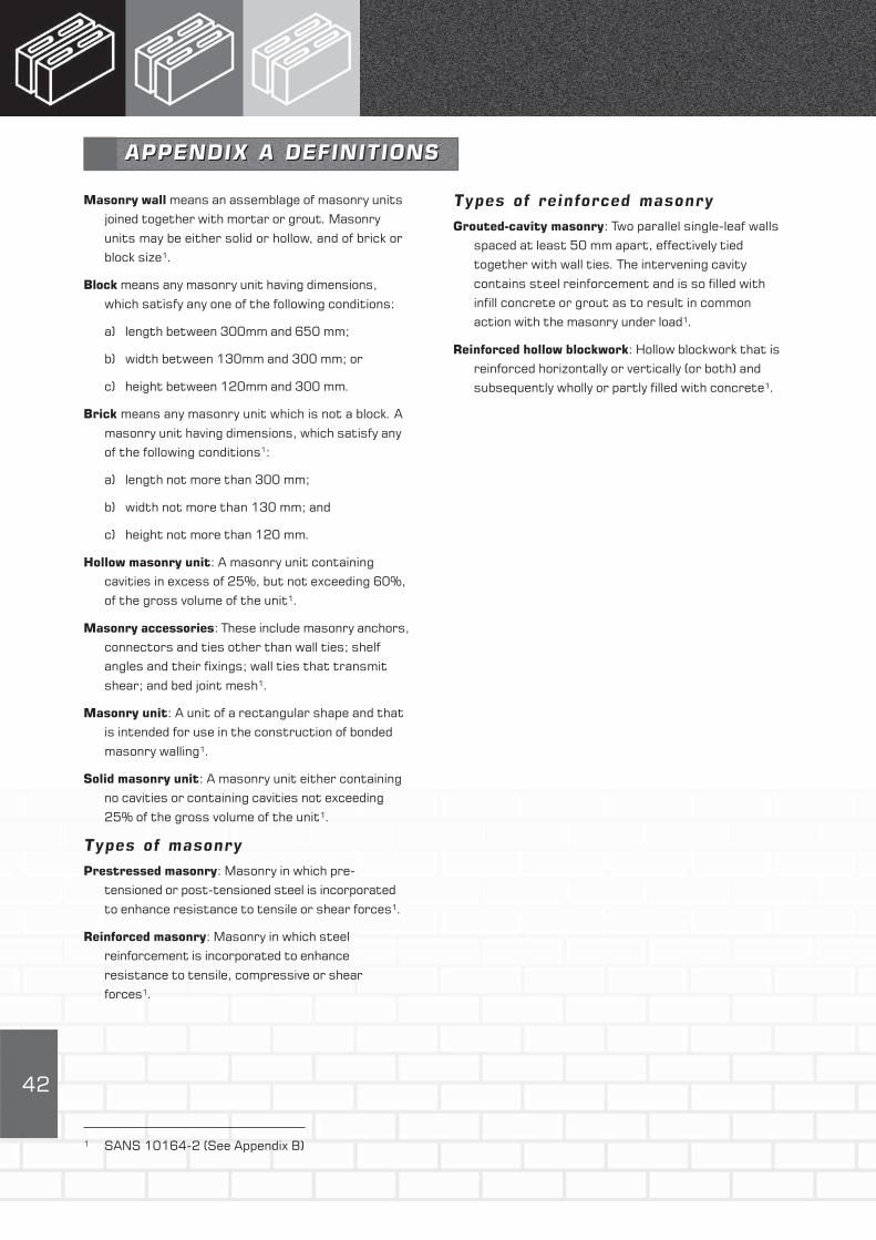
APPENDIX A DEFINITIONS
Types of reinforced masonry
Grouted-cavity masonry: Two parallel single-leaf walls
spaced at least 50 mm apart, effectively tied
together with wall ties. The intervening cavity
contains steel reinforcement and is so filled with
infill concrete or grout as to result in common
action with the masonry under load¹.
Reinforced hollow blockwork: Hollow blockwork that is
reinforced horizontally or vertically (or both) and
subsequently wholly or partly filled with concrete¹.
Masonry wall means an assemblage of masonry units
joined together with mortar or grout. Masonry
units may be either solid or hollow, and of brick or
block size¹.
Block means any masonry unit having dimensions,
which satisfy any one of the following conditions:
a) length between 300mm and 650 mm;
b) width between 130mm and 300 mm; or
c) height between 120mm and 300 mm.
Brick means any masonry unit which is not a block. A
masonry unit having dimensions, which satisfy any
of the following conditions1:
a) length not more than 300 mm;
b) width not more than 130 mm; and
c) height not more than 120 mm.
Hollow masonry unit: A masonry unit containing
cavities in excess of 25%, but not exceeding 60%,
of the gross volume of the unit¹.
Masonry accessories: These include masonry anchors,
connectors and ties other than wall ties; shelf
angles and their fixings; wall ties that transmit
shear; and bed joint mesh¹.
Masonry unit: A unit of a rectangular shape and that
is intended for use in the construction of bonded
masonry walling¹.
Solid masonry unit: A masonry unit either containing
no cavities or containing cavities not exceeding
25% of the gross volume of the unit¹.
Types of masonry
Prestressed masonry: Masonry in which pre-
tensioned or post-tensioned steel is incorporated
to enhance resistance to tensile or shear forces¹.
Reinforced masonry: Masonry in which steel
reinforcement is incorporated to enhance
resistance to tensile, compressive or shear
forces¹.
APPENDIX A DEFINITIONS

43
APPENDIX B REFERENCESAPPENDIX B REFERENCES
SANS 10145-2000
Concrete masonry construction
SANS 10155-1980
Accuracy in buildings
SANS 10249-1990
Masonry walling
MATERIALS OF CONSTRUCTIONAggregates
SANS 794- 2002
Aggregates of low density
SANS 1083- 2002
Aggregates from natural sources
Cement
SANS 50197-1:2000
Cement – Composition, specifications and
conformity criteria
Part 1: Common cements
SANS 50413-1:2004
Masonry cement
Part 1: Specification
Dampproof courses
SANS 248-1973 (2000)
Bituminous dampproof course
SANS 298-1975 (1999)
Mastic asphalt for dampproof courses and tanking
SANS 952-1985 (2000)
Polyolefin film for dampproofing and waterproofing
in buildings
Reinforcement
SANS 190-2:1984 (2001)
Expanded metal building products
SANS 920-1985 (2000)
Steel bars for concrete reinforcement
SANS 1024-1991
Welded steel fabric for reinforcement of concrete
Lime
SANS 523- 2002
Limes for use in building
Sand
SANS 1090- 2002
Sand for plaster and mortar
STANDARDS ON THE USE OFCONCRETE MASONRY
MANUFACTURE OF CONCRETE MASONRY UNITS
SANS 1215 – 1984 (2002) Concrete masonry units
USE OF MASONRY UNITS
Planning, design and specifications
SANS 993-1972 (2002)
Modular coordination in building
SANS 10021-2002
Waterproofing of buildings
SANS 10155-1980 (2000)
Accuracy in buildings
NBRI R/Bou – 602
Fire resistance ratings – walls constructed of
concrete blocks
National Building Regulations
National Building Regulations and Building Standards
Act 1977 revised 1990
SANS10400-1990
Application of the National Building Regulations
SANS10401-1989
The construction of dwelling houses in accordance
with the National Building Regulations
Structural Design
SANS 10100- 1:2000
The structural use of concrete
Part 1: Concrete
SANS 10160 -1989
The general procedures and loadings to be adopted
for the design of buildings.
SANS 10161-1980
The design of foundations for buildings
SANS 10164
The structural use of masonry
Part 1-1980 (2000): Unreinforced masonry
Part 2-2003: Reinforced and
prestressed walling
SANS 1504 -1990 (2002): Prestressed concrete
lintels
Concrete Masonry Construction
SANS 10073-1974
Safe application of masonry-type facings to
buildings
44
USEFUL BRITISH STANDARDS
BS EN 12878- (1999)
Pigments for portland cement and portland cement
products
BS 4551-1998
Methods of testing mortars, screeds and plasters
BS 4887
Mortar admixtures
Part 1: 1986: Specification for air-entraining
(plasticizing) admixtures
Part 2: 1987: Specification for set retarding
admixtures
BS 5224- 1976
Specification for masonry cement
BS 6477-1984
Water repellents for masonry surfaces
CONCRETE MANUFACTURERSASSOCIATION PUBLICATIONS
Masonry Manual 7th edition, Johannesburg 2005
Free-standing walls Design guide
Technical note: Unreinforced
Reinforced

45
TYPICAL SECTIONAL
ELEVATION STRAP FIXED TO
COLUMN
DIAGRAMATIC SKETCH OF STRAP
MOVEMENT WITH MASONRY
SHRINKING AWAY FROM COLUMN
AT TIME OFINSTALLATION
SUBSEQUENTLY
Strap anchored tocolumn
Wall
Metal strap
AnchorAnchor
Lifting ofcorner –openingo fbeddingjoint
Concrete column
Movement
APPENDIX C ANCHORS – WALLS
Anchors are used for tying metal straps, angles and
wall accessories to masonry, concrete or steel, at
wall/concrete, wall/wall, wall/steel intersections, or to
support a leaf of a wall or service. Anchors function by
being held in position in the base material by
friction, keying, bonding or a combination of these
factors. Essentially the fixing of anchors to any
member requires either the drilling of a hole to
house the anchor, or the firing of the anchor into the
supporting material.
In general terms shot-firing anchors into brittle
material such as concrete or masonry may shatter the
material and the quality of support may then become
suspect. Drilling is preferable where anchorage stress
level is significant.
Firing into ductile materials such as steel or timber is
an easy and quick method of anchoring.
In both cases the amount of force exerted in drilling or
shot firing should not disturb the bonding of masonry
units to adjacent units.
The position of the anchor is important in ensuring
optimum load carrying capacity.
In the case of angles supporting a non-structural outer
leaf of a wall to the main structure then the position
of the hole in the vertical leg of the angle should be as
near the top of the angle as possible. It is also
preferable to use an unequal angle with the longer leg
of the angle in the vertical direction.
With straps holding walls to columns to provide lateral
support, the anchor should be placed as near as
possible to the right angle bend in the strap. This is to
prevent the straightening out of the bend, with, say,
shrinkage of the wall, which would tend to lift the
masonry unit above the horizontal section of the strap,
opening the bedding joint.
Normally a single anchor in the vertical leg of the
strap is adequate but if two anchors are necessary
then the spacing of these anchors should be such as
not to reduce the overall anchorage. When shot firing
into brittle materials the spacing should be at least
100 mm.
Heated drawn steel should be used for straps that are
bent and twisted. Normally stainless steel cannot be
shaped to the required shape.
The type, size and position of anchorage to be shown
on drawings and/or clearly specified.
APPENDIX C ANCHORS – WALLS

46
Types of Anchor (refer SANS 10400)
APPENDIX D ROOFING FIXINGAPPENDIX D ROOFING FIXING
Roof Slope, Max Type of anchor required
Degrees Roof Truss, Rafter or
Beam spacing, mm Light Roof Heavy Roof
Less than 15 760 A,B or C Not
1050 B or C Applicable
1400 C
15-30 760 A, B or C Type A for
1050 B or C all
1400 C applications
Greater than 30 Any A,B or C
Anchors
Type A: 2 Strands 4 mm Galvanised Steel Wire
Type B: 30 mm x 1.2 mm Galvanised Steel Strap
Type C: 30 mm x 1.6 mm Galvanised Steel Strap
Length of Type of Roof
Anchorage
300 mm Heavy roof
(Concrete or clay
tiles or slate)
600 mm Sheeted Roof
Note:
Details of types of anchors apply to buildings not
exceeding two storeys in height and where span of the
roof truss does not exceed 10 m.

47
AP
PE
ND
IX E
: T
IES
, S
TR
AP
AN
D B
ED
DIN
G R
EIN
FO
RC
EM
EN
T
Type
Ladder T
ype
Truss T
ype
Mesh/L
athin
g for r
ein
forcem
ent a
nd t
yin
g
intersectin
g leaves o
f w
all
Descripti
on
Two longit
udin
al w
ires
Two longit
udin
al w
ires
Rectangula
r w
ire g
rid
Dia
gonal f
lat e
xpanded m
etal
wit
h t
ransve
rse w
ires
wit
h d
iagonal t
ransve
rse
wit
h d
iam
ond s
hape o
penin
gs
wir
es.
Ske
tch
Wid
th (
w), m
m75/1
50/2
30
60/1
10/1
60
50/1
50
65
/75
/12
5
Dia
meter
of w
ire, m
m2,5
/2,8
/3,1
5/3
,55
3,2
5/3
,55
3,1
50
,8 m
m t
hic
k p
late
Wir
e s
pacin
g (s), m
m50
Siz
e o
f openin
g1
0 x
30
b x
l,m
m
Length r
olls
, m
20/2
525
100
Length fla
ts, m
33
3C
ut t
o 2
50
mm
Siz
e o
f sheet,
m x
m1
,2 x
2,4
Note:
Wir
e m
anufa
cture
d for
Only
ava
ilable
fla
tD
imensio
n a
nd
Dim
ensio
ns a
nd p
ropert
ies t
o b
e
beddin
g jo
int
pro
pert
ies t
o b
econfirm
ed w
ith local supplie
r.
rein
forc
em
ent fro
m h
igh
confirm
ed w
ith local
Consid
er
stro
nger
tie
s if la
tera
l
tensile
steel s
hould
supplie
rlo
ad t
ransfe
r is
sig
nific
ant
pre
fera
bly
be fla
t i.e
. not
in r
olls
.
Check
ava
ilabili
ty a
nd q
ualit
y. F
or
qualit
y, c
heck
if c
om
merc
ial or
stated q
ualit
y, w
hether
mild
, galv
anis
ed o
r stain
less s
teel, o
r coated for
corr
osio
n r
esis
tance.
w
AP
PE
ND
IX E
: T
IES
, S
TR
AP
AN
D B
ED
DIN
G R
EIN
FO
RC
EM
EN
T
ww
lw
b
DE
TA
ILS
OF
RE
INF
OR
CE
ME
NT
US
ED
IN
BE
DD
ING
JO
INT
S

48
Hoop Iron
Straps
Rods/B
ars
Wall T
ies
Purp
ose
Anchori
ng r
oof
Wall
to w
all
slid
ing
– A
nchori
ng
Rein
forc
em
ent o
f:C
onnectin
g t
wo leave
s o
f a c
avi
ty w
all
to
tru
sses t
o w
alls
join
ts– c
oncre
te a
nd s
teel
– b
eddin
g join
tensure
that t
he w
all
acts a
s a
unit
in
(Concert
ina s
tra
p)
colu
mns t
o w
alls
– h
ollo
w u
nit
core
resis
tin
g a
pplie
d lo
ads.
– A
nchori
ng w
alls
to
– c
avi
ty
– In m
ult
ileaf w
alls
ensure
s
walls
/slid
ing join
tB
ars
can b
e u
sed in
monolit
hic
actio
n
– w
all
to w
all
slid
ing
pla
ce o
f stra
ps for
– In d
iaphra
gm
walls
pro
vides s
hear
join
tsanchora
ge.
tra
nsfe
r betw
een w
eb a
nd fla
nge
Mate
rial
Norm
ally
cut fro
m o
ff c
uts o
f ro
lls o
f sheet
Norm
ally
cut fro
m fla
tM
ild s
teel or
hig
h t
ensile
Materi
al determ
ined b
y t
he lik
elih
ood o
f
steel – r
egard
ed a
s c
om
merc
ial qualit
ysteel s
heets –
regard
ed
steel. M
ay
be s
tain
less
corr
osio
n v
iz. galv
anis
ed m
ild s
teel,
as s
tate
d q
ualit
ysteel or
coated for
copper, c
opper-
zin
c o
r auste
nit
ic
corr
osio
n r
esis
tance
sta
inle
ss s
teel
Shape
Fla
tC
oncert
ina a
t join
tFla
tR
ound, sm
ooth
,O
f va
rious s
hapes
defo
rmed o
r in
dented
Thic
kness, m
m1,2
/1,6
1,2
/1,6
2,5
/3,0
1,5
4,0
Wid
th, m
m30
25
30
40
30
40
13
20
Dia
meter, m
m6<
Ø<
32
2,8
3,1
5
4,0
4,5
Fix
ing
One e
nd o
f stra
pB
oth
ends
One e
nd o
f stra
pPla
ced in
Pla
ced in
beddin
g m
ort
ar
em
bedded in
concre
teem
bedded in
em
bedded in
concre
te–
beddin
g jo
int
in c
ore
of unit
or
inm
ort
ar
join
tin
core
of unit
, or
in–
core
hollo
w u
nit
,
beddin
g jo
int m
ort
ar,
beddin
g jo
int m
ort
ar,
–bond a
nd U
-beam
s,
other
end fix
ed t
o r
oof
other
end fix
ed b
y shot-
–cavi
ty
walls
tru
ss o
r w
all
pla
te.
firi
ng b
olt
s/p
ins in
to
and fill
ed w
ith
steel or
dri
lling a
nd
mort
ar
or
infill
See A
ppendix
D.
bolt
ing in
to c
oncre
teconcre
te
For
slid
ing join
ts, one
Genera
l requir
em
ents
for
end g
reased
pro
visio
n o
f tie
s
Siz
e o
f cavi
ty
Tie
s/m
²
<75 m
m2,5
75
– 1
00
mm
3
10
0 –
15
0 m
m5
Check
materi
al p
rovi
din
g c
onnectio
n b
etw
een s
tru
ctura
l masonry
ele
ments c
an s
afe
ly t
ransfe
r lo
ads a
nd forc
es w
hile
pro
vidin
g la
tera
l support
.
DE
TA
ILS
OF
ST
RA
PS
, T
IES
AN
D R
EIN
FO
RC
EM
EN
T

49
R B Watermeyer Pr. Eng. B Sc Eng, MSAICE,
MSAConsE Soderlund & Schutte Inc.
1. INTRODUCTION
Drawings depicting details of reinforcement in
masonry elements, supplemented by specifications are
required to translate designs into physical realities.
Detailing is therefore the most important link between
good design and quality construction. Accordingly
detailing of reinforcement should be kept simple, clear
and practical while drawings should clearly define and
depict the design requirements in a comprehensible
manner. SANS 10164-2 offers guidance in this regard,
the main provisions of which are highlighted and
illustrated hereunder.
Reinforcement should be located to suit simple
masonry bonding patterns. Cutting of masonry units
should be kept to a minimum while the bonding of
masonry should be such that an adequate void for
grouting is maintained. Common practical bonding
arrangements are illustrated below.
The detailing of reinforced masonry differs somewhat
to that of reinforced concrete; the principle
differences being:
distribution steel is not required in certain
masonry bonding patterns since bonded masonry
can often span and distribute forces between
reinforcing bars.
reinforcing bars often have to be protected against
corrosion in reinforced masonry applications where
mortar infill is employed.
the characteristic anchorage bond strength
between mortar and steel is significantly less than
that between concrete and steel.
2. MORTAR AND CONCRETEINFILL (SANS 10164-2)
Only Class I and Class II mortar (refer to SANS
10164-1) should be used in the bedding course for
reinforced masonry applications. Where masonry
cement is used, the bond between steel and mortar
should be investigated.
Infill concrete should be grade 25 concrete or better.
Mixes should have adequate workability with a slump
of between 75 and 175mm. The nominal aggregate in
such concrete should be at least 5 mm less than the
permitted cover to any reinforcement.
APPENDIX F DETAILING PRACTICE FORREINFORCED MASONRYAPPENDIX F DETAILING PRACTICE FORREINFORCED MASONRY
GROUTED CAVITY POCKET TYPE
HOLLOW UNITS QUETTA BOND
BED JOINT
50
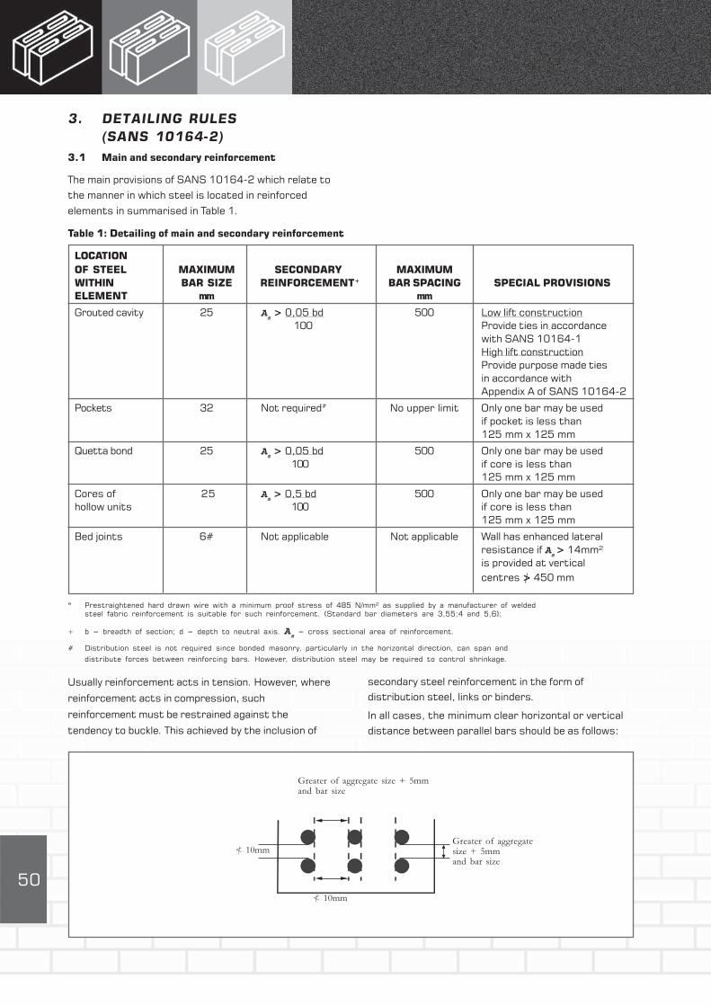
3. DETAILING RULES(SANS 10164-2)
3.1 Main and secondary reinforcement
The main provisions of SANS 10164-2 which relate to
the manner in which steel is located in reinforced
elements in summarised in Table 1.
Table 1: Detailing of main and secondary reinforcement
LOCATION
OF STEEL MAXIMUM SECONDARY MAXIMUM
WITHIN BAR SIZE REINFORCEMENT+ BAR SPACING SPECIAL PROVISIONS
ELEMENT mm mm
Grouted cavity 25 As > 0,05 bd 500 Low lift construction
100 Provide ties in accordance
with SANS 10164-1
High lift construction
Provide purpose made ties
in accordance with
Appendix A of SANS 10164-2
Pockets 32 Not required# No upper limit Only one bar may be used
if pocket is less than
125 mm x 125 mm
Quetta bond 25 As > 0,05 bd 500 Only one bar may be used
100 if core is less than
125 mm x 125 mm
Cores of 25 As > 0,5 bd 500 Only one bar may be used
hollow units 100 if core is less than
125 mm x 125 mm
Bed joints 6# Not applicable Not applicable Wall has enhanced lateral
resistance if As
> 14mm²
is provided at vertical
centres > 450 mm
* Prestraightened hard drawn wire with a minimum proof stress of 485 N/mm² as supplied by a manufacturer of welded
steel fabric reinforcement is suitable for such reinforcement. (Standard bar diameters are 3,55;4 and 5,6);
+ b = breadth of section; d = depth to neutral axis. As = cross sectional area of reinforcement.
# Distribution steel is not required since bonded masonry, particularly in the horizontal direction, can span and
distribute forces between reinforcing bars. However, distribution steel may be required to control shrinkage.
Usually reinforcement acts in tension. However, where
reinforcement acts in compression, such
reinforcement must be restrained against the
tendency to buckle. This achieved by the inclusion of
secondary steel reinforcement in the form of
distribution steel, links or binders.
In all cases, the minimum clear horizontal or vertical
distance between parallel bars should be as follows:
Greater of aggregate size + 5mmand bar size
Greater of aggregatesize + 5mmand bar size
< 10mm
< 10mm

51
1.2 Anchorage bond, laps and joints
For reinforcement to develop the design stress, it
must be adequately bonded into the surrounding
masonry. This may be achieved by ensuring that:
the cover of concrete or mortar infill is at least
equal to the bar diameter; and
a sufficient length of bar (anchorage length)
extends beyond any section to develop the
necessary force at that section.
The length of bar required for anchorage purposes
(lba
) may be calculated as follows:
lba= f
y
mb Ø = K Ø
4 ms f
b
where:
Ø = nominal bar diameter
mb= partial safety factor for bond strength
ms
= partial safety factor for strength of steel
fb = characteristic anchorage bond strength
fy
= characteristic tensile strength of
reinforcing steel
As
= cross sectional area of steel
K = ratio of anchorage bond length to bar
diameter (see Table 2)
Thus 1ba required
= K Ø As required
As provided
52
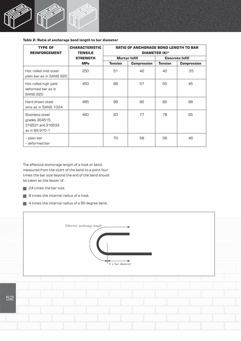
Table 2: Ratio of anchorage bond length to bar diameter
TYPE OF CHARACTERISTIC RATIO OF ANCHORAGE BOND LENGTH TO BAR
REINFORCEMENT TENSILE DIAMETER (K)*
STRENGTH Mortar Infill Concrete Infill
MPa Tension Compression Tension Compression
Hot rolled mild steel 250 51 42 42 35
plain bar as in SANS 920
Hot rolled high yield 450 68 57 55 45
deformed bar as in
SANS 920
Hard drawn steel 485 98 82 82 68
wire as in SANS 1024
Stainless steel 460 93 77 78 65
grades 304515,
316531 and 316533
as in BS 970-1
– plain bar 70 58 56 46
– deformed bar
The effective anchorage length of a hook or bend,
measured from the start of the bend to a point four
times the bar size beyond the end of the bend should
be taken as the lesser of:
24 times the bar size.
8 times the internal radius of a hook.
4 times the internal radius of a 90 degree bend.
Effective anchorage length
4 x bar diameter
53
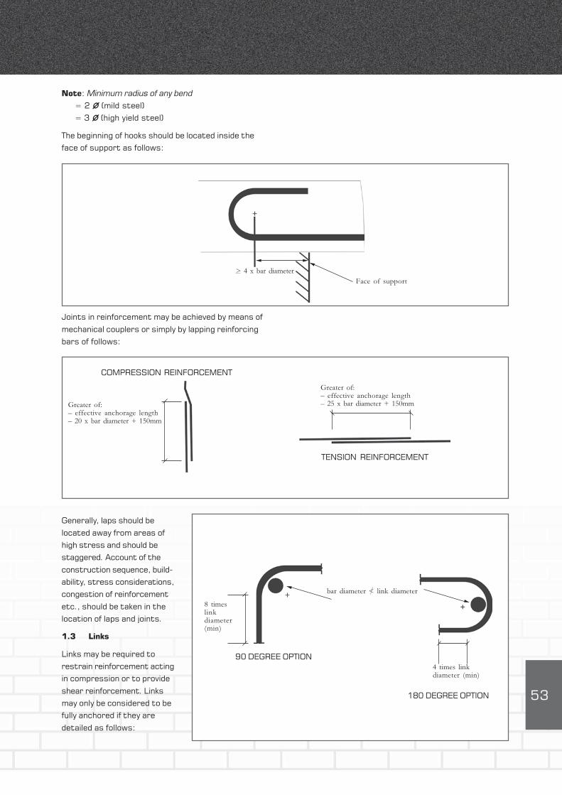
Note: Minimum radius of any bend
= 2 Ø (mild steel)
= 3 Ø (high yield steel)
The beginning of hooks should be located inside the
face of support as follows:
Face of support
Joints in reinforcement may be achieved by means of
mechanical couplers or simply by lapping reinforcing
bars of follows:
Generally, laps should be
located away from areas of
high stress and should be
staggered. Account of the
construction sequence, build-
ability, stress considerations,
congestion of reinforcement
etc., should be taken in the
location of laps and joints.
1.3 Links
Links may be required to
restrain reinforcement acting
in compression or to provide
shear reinforcement. Links
may only be considered to be
fully anchored if they are
detailed as follows:
> 4 x bar diameter
COMPRESSION REINFORCEMENT
Greater of:– effective anchorage length– 20 x bar diameter + 150mm
Greater of:– effective anchorage length– 25 x bar diameter + 150mm
TENSION REINFORCEMENT
180 DEGREE OPTION
8 timeslinkdiameter(min)
4 times linkdiameter (min)
90 DEGREE OPTION
bar diameter < link diameter

54
Shear reinforcement links in beams should be provided
as follows:
bb
d
Bond block
Hollow block
Lintel block
SOLID UNITS HOLLOW UNITS
Link spacing (sv)
sv < 0,75d
Nominal link area Asv
Mild steelAsv = 0,002b
sv
High yield steelAsv = 0,0012b
sv
Where compression steel is
used in beams, links should be
provided as for columns. Column
links are required when the area
of steel exceeds 0,25% of the
gross area of the column and
the design load exceeds 25% of
the resistance capacity of the
column. In such circumstances,
links should be proved as
follows:
SOLID UNITS
1st course 2nd course
HOLLOWUNITS
Link spacing (sv)
sv
> 20 x bar diameter> 50 x link diameter> least lateral columndimension
Note:
Link spacing for internalbars > 2s
v
3.4 Curtailmentof bars
Reinforcing bars acting in
tension at simply supported
ends of members should be
terminated as follows:
12 x bar diameter
d
of supportor
d/2

55
However, should the distance between the face of the
support and the edge of the nearest principal load be
less than twice the effective depth, reinforcement
should be curtailed as follows:
Reinforcing bars which are subjected to bending and
terminate other than at an end support, should
continue for a distance beyond the point at which they
are no longer required, equal to the greater of the
effective depth of the member or12 times the bar
size, provided, however, that one or more of the
following is satisfied:
bars extend for a distance at least equal to the
effective anchorage bond length;
the design shear strength of the section is at least
twice that of the applied shear force;
the remaining reinforcement provides at least
twice the area of reinforcement required to resist
the applied bending moment.
of supportor
d/2
d
20 x bar diameter <2d
Principalload

56
4. RESISTANCE OF METALCOMPONENTS TO CORROSION(SANS 10164-2)
4.1 General
The resistance of metal components to corrosion
depends upon the following:
exposure environment
type and quality of cementitious surround, i.e.,
mortar or infill concrete
cover
type of protective coating of steel.
SANS 10164-2 contains recommendations regarding
the minimum levels of protective coatings for
reinforcement and masonry accessories used in
various types of construction and exposure conditions.
These recommendations are not necessarily the
desirable levels of protection that may be required
since local conditions or specific circumstances may
warrant a higher degree of protection.
Table 3: Classification of exposure conditions
EXPOSURE EXPOSURE ENVIRONMENTS FOR SURFACES OF
CLASSIFICATION REINFORCED MEMBERS
E1 Protected by an impermeable membrane
Exposed to the elements in
inland areas as shown in Figure 1.
interiors of buildings.
Beneath coatings that resist moisture penetration.
E2 Exposed to the elements in:
inland areas as shown in Figure 1.
interiors of industrial buildings where humidity is high or
where repeatedly washed.
Submerged in non-aggressive soils.
E3 Exposed to the elements in:
areas within 3 km of industries that discharge atmospheric pollutants.
areas within 1 km of the coastline or shoreline of large expanses of salt water.
Submerged in fresh water.
S Submerged in aggressive soils.
Submerged in sea water, running water or soft water.
In contact with corrosive liquids or gas.
4.2 Exposure classification
The exposure classification may be established from
Table 3 and Figure 1 or Table 17 of SANS 10164-2.
Elements which may be subjected to more severe
exposure than the remainder of a building, such as
parapets, chimneys and sills should be regarded as
being located in an environment classified as E3.

57
4.3 Corrosion protection
The degree and type of corrosion protection required,
if any, for various types of steel should be determined
in accordance with Table 4, read in conjunction with
Table 5. The zinc coating on galvanised steel ties
should be at least equal to that in Table 2 of
SANS 935 for normal environments and 470 g/m² for
highly corrosive environments.
FIGURE 1: EXPOSURE ENVIRONMENTS
LEGEND
E1
E2
Worcester
Cape Town Port Elizabeth
East London
Durban
Oudtshoorn
Barkly West
Upington Bloemfontein
Mafikeng Johannesburg
Nelspruit
Pietersburg
Empangeni
Richards BayEstcourt
Table 4 : Corrosion-resistance rating for steel in masonry
CORROSION- TYPE, OR COATING, OF STEEL (OR BOTH)
RESISTANCE RATING
C1 Uncoated carbon steel; or steel whose coating is less
than required for C2 rating.
C2 Galvanized steel; for products made from:
a) sheet steel – the coating class shall be at least Z 275 as in SANS 934;
b) wire of circular cross-section up to 6,0 mm diameter – the coating
shall be as for class A wire in Table 2 of SANS 935;
c) other forms of steel – the coating mass shall be as in Table 1 of SANS 763.
C3 Galvanized steel; for products made from:
a) sheet – the coating class shall be at least Z 600 as in SANS 934.
b) other forms of steel – the coating shall be as for rating C2.
C4 Steel, or steel coating, whose type and thickness are specially selected to
withstand the particular corrosive conditions to which that steel and its
masonry may be exposed.

58
4.4 Cover
Cover to reinforcement should be as follows:
Table 5: Selection of reinforcement for durability
LOCATION OF REINFORCEMENT EXPOSURE CORROSION
CLASSIFICATION RESISTANCE
Located in grouted cavities or in
Quetta bond construction
a) where concrete infill E1, E2 and E3 C1 or higher
employed S C4
b) where mortar infill is E1 C1
employed E2 and E3 C2 or higher
S C4
In bed joints E1 C1 or higher
E2 C2 or higher
E3 C3
S C4
POCKET TYPE QUETTA BOND
HOLLOW UNITS BED JOINT
15mm minimum
Recommended minimumcover given in Table 6
Recommended minimumcover given in Table 6
Recommended minimumcover given in Table 6

59
Table 6: Minimum concrete cover for carbon steel reinforcement
MINIMUM THICKNESS OF CONCRETE COVER, mm
Concrete grade (as in SANS 10100)
EXPOSURE 25 30 35 40
CONDITION Minimum cement content kg/m³
250 300 350 350
E1 20 20 20 20
E2 – 30 30 25
E3 – 40 35 30
S – – – 60
The tooling of mortar joints gives a dense, water-
shedding finish. Tooling of joints should be undertaken
in elements located in environments which are
classified as E3 or S.
5. FIRE RESISTANCE
SANS 10164-2 does not contain any guidance on the
fire resistance of reinforced elements and simply
makes reference to a code which is still in the course
of preparation. BS 5628 Part 2 (Structural use of
Reinforced and Prestressed Masonry) suggests that
the masonry itself be considered as part of the cover
and that the recommendations of BS 8110 (Structural
use of Concrete) be followed. AS 3700 (SAA Masonry
Code), on the other hand, specifies a minimum cover
to the reinforcement for a specific fire resistance
period. (See Table 7).
Table 7: Protection to reinforcement for structural adequacy (AS 3700)
FIRE RESISTANCE PERIOD, MINUTES 30 60 90 120 180 240
Minimum dimension from the reinforcement to the
exposed face of the masonry, mm 30 30 30 40 55 65

60
APPENDIX G V-JOINTS IN PLASTER AND MORTARAPPENDIX G V-JOINTS IN PLASTER AND MORTAR
JUNCTION OF TWO WALLS AT CONTROL JOINT
JUNCTION OF WALL WITH CONTROL COLUMN
Pla
ster
V-joint cutinto corner
Plaster
Wall
Pla
ster
Wall
Cut mortar toshape shown
Wall
Plaster
Wall
Concretecolumn
PLAN
PLAN PLAN
Concretecolumn
Cut plaster toshape shown