detailed design report - middle east technical university
TRANSCRIPT

1
RAILWAY INFORMATION SYSTEM
CENG 491 Computer Engineering Design
Detailed Design Report
BUGBUSTERS
18.01.2010
Burkay SUCU
Caner ÇAKMAK
Halim Çağrı ATEŞ
Işıl Özge PEKEL

2
Table of Contents 1. Introduction ................................................................................................................................................................... 5
1.1. Purpose of the Document ............................................................................................................................. 5
1.2. Scope of the Document ................................................................................................................................. 5
1.3. Abbreviations ..................................................................................................................................................... 5
2. Project Description .................................................................................................................................................... 6
2.1. Project Title ......................................................................................................................................................... 6
2.2. Detailed Problem Definition......................................................................................................................... 6
2.3. Project Definition and Goals ....................................................................................................................... 7
3. Design Constraints and Working Environment ........................................................................................... 7
3.1. Design Constraints .......................................................................................................................................... 7
3.2. Assumptions....................................................................................................................................................... 8
3.2.1. Hardware Assumptions ....................................................................................................................... 8
3.2.2. Software Assumptions ......................................................................................................................... 8
3.2.3. Schedule Assumptions ........................................................................................................................ 8
3.2.4. Network Communication ..................................................................................................................... 8
3.2.5. Best Path Search Assumptions ....................................................................................................... 9
3.3. Working Environment .................................................................................................................................... 9
4. System Modules.......................................................................................................................................................... 9
4.1. User Module ........................................................................................................................................................ 9
4.1.1. Registration Submodule ...................................................................................................................... 9
4.1.2. Login Submodule ................................................................................................................................... 9
4.1.3. Update Submodule ................................................................................................................................ 9
4.2. Scheduling Module ........................................................................................................................................10
4.3. Best Path Search Module ...........................................................................................................................10
4.4. News Module ....................................................................................................................................................10
4.5. Journey Module ...............................................................................................................................................10
4.6. Knowledge Database Module ...................................................................................................................11
4.7. Hardware Modules .........................................................................................................................................11
4.7.1. GPS Submodule ....................................................................................................................................11
4.7.2. Accelerometer Submodule...............................................................................................................11
4.7.3. Internet Communication Submodule ..........................................................................................11
5. Architectural Design ...............................................................................................................................................11
5.1. Overall Design..................................................................................................................................................11
5.2. Sequence Diagrams ......................................................................................................................................13
5.2.1. Registering New Users.......................................................................................................................13
5.2.2. Logging into the System ...................................................................................................................14

3
5.2.3. Updating Personal Information ......................................................................................................15
5.2.4. Live Train Monitoring for Passengers ........................................................................................17
5.2.5. Live Train Monitoring for Machinists ..........................................................................................19
5.2.6. Travel Planning ......................................................................................................................................20
5.2.7. Adding / Reading News......................................................................................................................21
5.2.8. Knowledge Database ..........................................................................................................................23
5.2.9. Creating a New Question ..................................................................................................................26
5.2.10. Scheduling ...............................................................................................................................................27
5.3. Activity Diagrams ................................................................................................................................................29
5.3.1. Login Activity Diagram.......................................................................................................................29
5.3.2. Train Monitoring Activity Diagram................................................................................................30
5.3.3. Adding New Question Activity Diagram ....................................................................................31
5.3.4. Best Path Activity Diagram ..............................................................................................................32
5.4. Class Diagram ............................................................................................................. 33
6. Data Design .................................................................................................................................................................36
6.1. Entity – Relationship Diagram..................................................................................................................36
6.2. Database Schemas ........................................................................................................................................37
6.2.1. USER table ...............................................................................................................................................37
6.2.2. Passenger table .....................................................................................................................................37
6.2.3. Best_Paths table ...................................................................................................................................37
6.2.4. Trains table ..............................................................................................................................................38
6.2.5. Stations table ..........................................................................................................................................38
6.2.6. Knowledge_DB table ...........................................................................................................................38
6.2.7. News table................................................................................................................................................38
6.2.8. Traintypes table .....................................................................................................................................39
6.2.9. Lines table................................................................................................................................................39
7. Interface Design ........................................................................................................................................................40
7.1. User Interfaces.................................................................................................................................................40
7.1.1. Registration Interface .........................................................................................................................40
7.1.2. Login Interface .......................................................................................................................................40
7.1.3. Update Information Interface ..........................................................................................................41
7.1.4. Knowledge Database Interface.......................................................................................................42
7.1.5. Optimum Cost / Optimum Time Search Interface..................................................................44
7.1.6. Passenger Tracking Interface .........................................................................................................45
7.1.7. Machinist Tracking Interface ...........................................................................................................46
7.1.8. Machinist Task Interface ...................................................................................................................47
8. System Design ...........................................................................................................................................................48

4
8.1. User Information Security ..........................................................................................................................48
8.2. Optimum Train Suggestion System .......................................................................................................48
8.3. Intelligent Machinist Assignment ...........................................................................................................48
8.4. Personal Information ....................................................................................................................................48
8.5. Live Train Monitoring ...................................................................................................................................49
8.6. Emergency Situations ..................................................................................................................................49
8.7. Railway Map ......................................................................................................................................................49
8.8. Contact Information .................................................................................................... 49
8.9. Knowledge Database .................................................................................................. 50
8.10. Database .................................................................................................................... 50
8.11. Webpage Design ........................................................................................................ 51
9. Project Schedule ................................................................................................................ 52
10. References......................................................................................................................... 54

5
1. Introduction
Current TCDD (Turkish State Railways) control system is based on signalization to
track the train positions. Although some trains have GPS devices, the GPS system
Savronik is rarely (almost never) used by system administrators. The
communication between administrators and locomotive drivers is established via
radiotelephones or mobile phones. A new communication system is being
constructed by Siemens nowadays. Administrators have no problem with signalization
system, do not like and use Savronik system, and describe the communication
system as messy. For the passengers side, TCDD provides an online system which
only provides ticket reservation and buying .
Railway Information System is intended to simplify the current complicated system
used at Turkish State Railways. Railway Information System will not only ease the
work for system administrators and machinists; but also it will improve and add new
features to the online system for passengers.
1.1. Purpose of the Document
In this document Railway Information System structure will be explained. This
structure will be constructed such that it will satisfy the requirements
mentioned in Software Requirements Specification.
In Software Requirements Specification, Railway Information System‟s
general features and requirements are mentioned. In this document, they will
be analyzed in detail.
1.2. Scope of the Document
This document covers the architectural design, data design, procedural
design, design constraints, and development schedule. Also hardware and
software requirements and working environment will be explained.
1.3. Abbreviations
RIS : Railway Information System
IMA : Intelligent Machinist Assignment
OTSS : Optimum Train Suggestion System
Some words in railway jargon:
Machine : The locomotive.
Brevet : The certificate to use a machine
Livre : The book containing speed/position tables

6
2. Project Description
2.1. Project Title
The title of the project is “Railway Information System”.
2.2. Detailed Problem Definition
One of the current system‟s problems is that there are many daily jobs and
most of them are done manually. Secondly some features of this system are
not public, which might be used to increase the public attention to railways if
they were. Another problem is that some services already in use in abroad
have not been introduced to TCDD customers yet.
There are many kinds of machines and a machinist is required to
have the special brevet to use a machine. Everyday hundreds of
machines goes from somewhere to somewhere and every machine
must be controlled by a machinist having the appropriate brevet. In
current system, the assignment of machine – machinist is done
daily and manually. Machinists learn the next day‟s schedule just
24 hours ago.
All railways in Turkey are partitioned and for every partition the
speed limit are determined. All these information are listed on
tables in a book called Livre. When a machinist starts the journey
from some point, he/she (he will be used later for convenience)
opens the relevant page of Livre. Near the railways, there are
position signs and with the help of them, machinists know their
positions. Knowing the position, a machinist looks up the speed
limit of that position from the Livre and adjusts the speed
accordingly. Machinists have to follow both the position signs and
the speed limit tables from beginning to the end of the journey.
Current system has been developed as time passed and new
technologies appeared. So it has been always built on the old one.
Each time taking care to preserve the backward compatibility,
adding new features have caused the current system to be very
complicated and dirty.
About 15 trains of TCDD already have a GPS device. But the
information fetched from these are visible to only some
supervisors, even machinists cannot see them.
In abroad, there exists some optimum cost / optimum time train
suggestion systems but there is not a similar system in Turkey.

7
2.3. Project Definition and Goals
Railway Information System is a project to enhance the service quality of
TCDD for machinists and administrators at TCDD and passengers by
eliminating the problems stated above.
The aims of the RIS project include:
Design a better train control system
o Automate the machinist – machine matching (IMA)
o Remove the “checking the speed limit from Livre” and replace it
with “checking needed information from machinist panel”
o In case of an emergency, establish a faster and easier
communication with control center and deliver the train position
more accurately
Attract public interest on railways
o Make the train position tracking public
o Implement a optimum time / optimum cost train suggestion system
o Meeting this goal means highly use of public transportation, less
traffic jam and accidents
The use of system will be made easier for all three categories of users
(passengers, machinists, administrators) with knowledge database, help
pages and manuals.
3. Design Constraints and Working Environment
3.1. Design Constraints
3.1.1. Time
In order to meet the deadlines and complete the project on time, team
members have to strictly obey the time constraints stated on Gantt chart.
3.1.2. Versioning
As soon as the implementation starts, different states of process have to be
versioned. SVN will be used as the version control system.
3.1.3. Financial Constraints
All implementation software and tools are open source except AutoCAD Map
3D . AutoDesk gives free license for this program to students.

8
3.2. Assumptions
3.2.1. Hardware Assumptions
In every train which will be included in Railway Information System, there will
be a netbook computer, a GPS device, and an accelerometer. Netbooks will
be connected to internet via a 3G modem. Because showing the current
speed, speed limit and angular information coming from accelerometer to the
machinist is a time critical mission, GPS device and accelerometer will be
directly connected to netbook. The sensitivity of GPS device is 1 meter.
3.2.2. Software Assumptions
Windows 7 Professional operating system will be used on netbooks.
Because showing the speed limit to the machinist is a time critical mission,
speed limit databases will be stored locally on netbooks. To query these
databases, as the database management system, MySQL will be installed
on netbooks. Even if the internet communication is lost, the system has to
work. So a web server is needed on netbooks, Apache HTTP server will be
installed for that purpose. To track the train positions on the map, MapGuide
Viewer will also be installed.
3.2.3. Schedule Assumptions
It is assumed that train schedules are 24 hours periodic, meaning if a train
leaves from station X at time t and goes to station Y, tomorrow it will again
leave from station X at time t and go to station Y.
Trains will be given five digit id numbers. The first digit will be 1, unless same
type train on the same line left the same station before that train. To clarify
with an example, assume 18540 is the id of the train which goes from Ankara
at 07.00 to İstanbul. If there is a same type train which will go from Ankara at
09.00 to İstanbul, then its id will be 28540. Also for the return, the id will be
one incremented if it is even and one decremented if it is odd. For the above
example, the returning train ids will be 18541 and 28541 respectively.
It is also assumed that there are not more than 9 same type trains on same
line on a day.
There will be 5 type of trains which will be symbolized with a letter from ‟A‟ to
„E‟.
3.2.4. Network Communication
During the journey of a train, the netbook will send the train id, GPS
information and accelerometer information to main server per 10 seconds. The
protocol of packages will be as TRAINID|GPSINFO|ACCINFO. „|‟ will be used
as the separator.

9
Main server will receive and process the incoming data. It will also send the
incoming data of a train to the other trains which are on the same line with it.
Main server will redirect the incoming packages also to the web server. To
decrease the processing load of the main server, public access to tracking
system will be to the web server.
3.2.5. Best Path Search Assumptions
To decrease the computational complexity, number of train changes will be
limited to 3 for the best path search module.
3.3. Working Environment
The system will be implemented on Java language. Users will be able to
reach the system within a browser page, so a java running server will be
needed. Apache HTTP server and Apache Tomcat will be used for that
purpose. The map implementation will be done on AutoCAD Map 3D. For
GPS simulation, java libraries will be used. NetBeans IDE will be used as
the development environment.
4. System Modules
4.1. User Module
4.1.1. Registration Submodule
Administrators and machinists will be preregistered to the system. They will be
informed about their accounts. Only passengers will register after the system is
started to be used. Registration will be done by selecting a username and a
password and supplying name, surname, telephone, e-mail, and birthday
information. Users are identified with unique usernames. The sequence diagram
of registration process is pictured in Figure 2.
4.1.2. Login Submodule
Login part of this module checks the user's username/password and gives access
to the system if username/password matches and opens a session for that user. If
a user forgets his/her password, user will be able to generate a confirmation e-
mail and reset the password by clicking the link being sent to his/her e-mail. The
sequence diagram of login process is pictured in Figure 3.
4.1.3. Update Submodule
Users will be able to update their information via update module. Only username
field will be unchangeable. If the user clicks “Kaydet” button, then the new
information on the form will be overwritten to the old information on the USER
database. If the user clicks “İptal” button, then the information on the database will
remain same. The sequence diagram of updating personal information process is
pictured in Figure 4.

10
4.2. Scheduling Module
The schedule of the next day is prepared by administrators by hand. It will be
edited in a csv (comma separated value) file . The structure of the file will be
machinistID, trainID. Administrator loads the file via scheduling module and the
entries in csv file are loaded to the relation table SCHEDULES. The scheduling
sequence diagrams for administrators and machinists are pictured in Figure 13
and Figure 14 respectively.
4.3. Best Path Search Module
When a passenger fills the form on the best path search page, the input fields
(departureStation, arrivalStation, dateInterval, timeInterval, maxFare, maxTime,
maxTrainChanges) are sent to the searchBestPath function. This function uses
the TRAINS database and searches for optimum paths according to given
parameters. The results will be showed to user. If user selects to save the query
results, they will be added to the BESTPATHS database with the userID.
Whenever a user opens the page “Seyir Defteri”, the saved search results will be
showed to the user. The sequence diagram of best path search is pictured in
Figure 7.
4.4. News Module
Administrators will add the news about some special offers such as a cutoff on
ticket prices with detailed information, due date and related trains. The entries will
be stored on NEWS database and relevant news (a query with trainIDs, in which
the user is interested, on NEWS table‟s relatedTrains field) will be showed to the
passengers on their home pages. The sequence diagrams of adding news and
reading news are pictured in Figure 8 and Figure 9 respectively.
4.5. Journey Module
A machinist logs in to the system via login module before the journey. After that,
the machinist module operates. The trainID is checked on SCHEDULE database
with current time and machinistID. Then from the TRAINS database, other
information for that train is fetched. Until the departure time, the home page of
machinist is displayed. On that page the current day‟s tasks for the machinist is
listed on that page, and a countdown clock to the departure time is showed. When
the departure time comes, the page will be automatically directed to the train
tracking page. On that page, the warning “Hareket saatiniz gelmiştir.” will be
displayed on the warning field of the page until the train moves. Train movement
will be decided with the velocity value coming from the GPS device. As soon as
the train moves, the map is centered on the train position (the coordinate values
are fetched from GPS device). Also with that coordinates, the current speed limit
is queried from SPEEDLIMIT database. Current speed, speed limit, departure
station, arrival station, expected arrival time information will be displayed on that
page on the right frame. In case the angle value coming from accelerometer
exceeds 23 degree, the warning “Tren devrilme tehlikesi, lütfen yavaşlayın.” will
be displayed. When the train arrive its last station, the machinist logs out and the

11
corresponding entry is deleted from the schedule database. Train tracking
sequence diagram for machinist is pictured in Figure 6.
4.6. Knowledge Database Module
Users will be able to search through four categories in Knowledge database of the
system. Frequently Asked Questions; include the questions most asked by
passengers and answered before. General Questions & Answers; includes some
question about some information about general structure of the system and
TCDD. Questions Waiting Answers are the questions added by the users and not
yet answered by administrators. The other category is Useful Links.
After the user enters the keywords, the entries from Knowledge Database are
returned and listed on the page. If User cannot find the question he is looking for,
he can add a new question to system. The user is required to enter the title and
choose the problem topic from menu. After the question is submitted, it will be
added to the Questions Waiting Answers until an admin enters the solution for the
problem. Knowledge database sequence diagrams are pictured in Figure 10,
Figure 11, and Figure 12.
4.7. Hardware Modules
4.7.1. GPS Submodule
GPS module establishes the connection of GPS device with netbook computer at
locomotive. NMEA protocol will be used for GPS data. JavaGPS will be
used to simulate GPS.
4.7.2. Accelerometer Submodule
Accelerometer module establishes the connection of accelerometer module with
notebook.
4.7.3. Internet Communication Submodule
Internet communication is needed to send and receive the GPS and
accelerometer information from trains to the main server and back from main
server to trains. This connection will be established via a 3G modem.
5. Architectural Design
5.1. Overall Design
There are many modules in Railway Information System. This modular structure
allows later modification of existing modules or integration of more modules in
case of a development in one device or technology being used. Also this modular
structure eases the implementation of the project.

12
As shown in Figure 1, every train contains a GPS device, an accelerometer
device, a netbook computer and a 3G modem. GPS and accelerometer
devices feed the information directly to the netbook. Netbook hosts the
SPEEDLIMIT tables, so even if the connection is lost with the main server,
there will be not critical failures. Via a 3G modem, netbook sends the
information packages to main server over http. Main server processes the
incoming packages, sends other trains ‟ information, which are on the same
line, back to the train. Main server also sends the packages to the web server.
Passengers may connect to the web server and track the trains they select.
The web server is separated from the main server in order to decrease the
load on the main server.
Figure 1 – Design Overview

13
5.2. Sequence Diagrams
5.2.1. Registering New Users
A new passenger who has not an account yet clicks to the link “Yeni Kullanıcı” on the Login Page.
The registration page will be opened. The passenger fills the registration form and click “Tamam” button to create an account
System creates a new entry in the passenger database if the required areas are filled properly.
Figure 2 - Registering sequence diagram
14
Otherwise:
o The system shows an error message if there is an empty required field in the registration form.
o The system shows an error message if the username the passenger types in registration form already exists.
Administrators create their own accounts and machinists‟ accounts directly by executing a query on the database table.
System encrypts all user information properly.
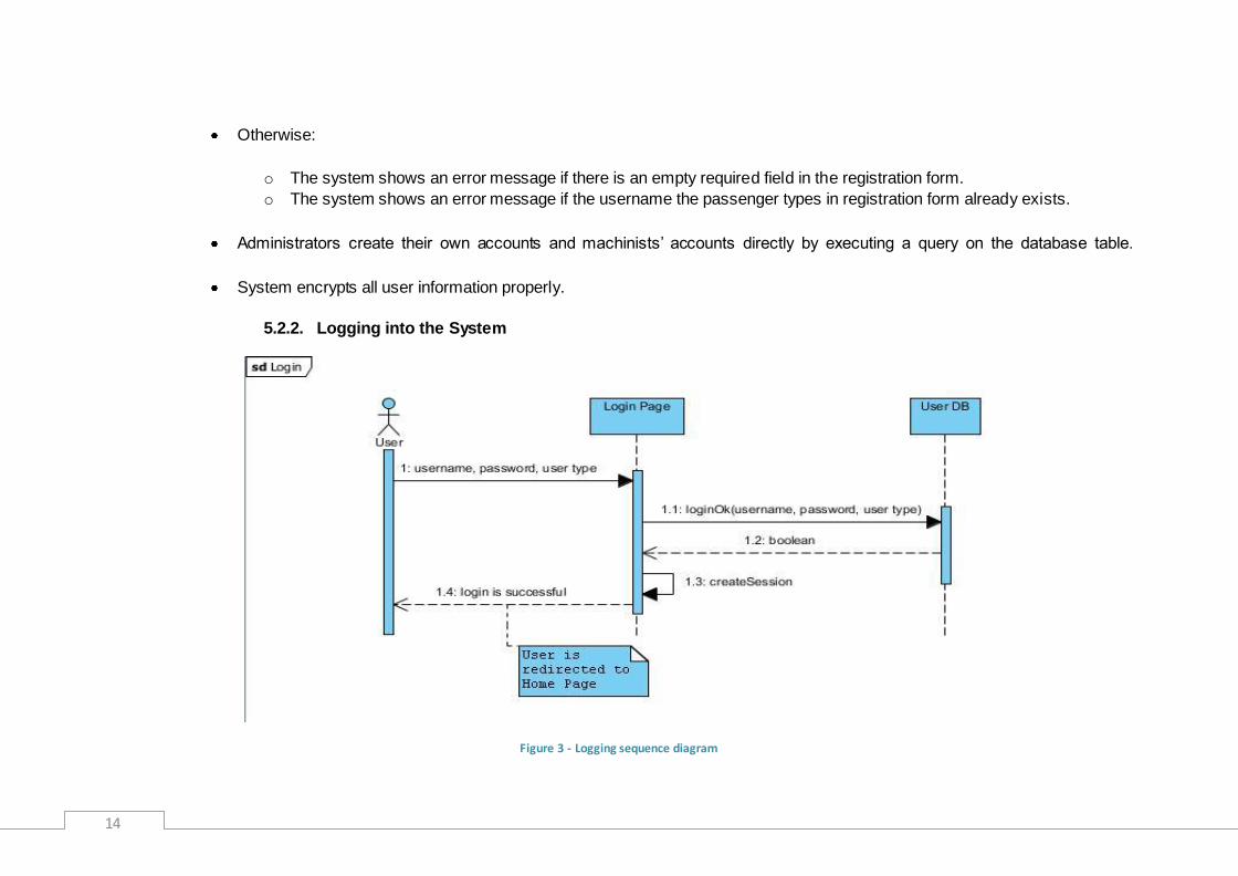
5.2.2. Logging into the System
Figure 3 - Logging sequence diagram

15
Users logs into the system via Login Page web interface. To log into the system, a user provides his username, password
and user type.
There are three user types: admin, machinist and passenger.
After filling username and password areas and selecting the user type, a user clicks Login button for confirmation.
5.2.3. Updating Personal Information
Figure 4 - Updating personal information sequence diagram
Passenger clicks the personal information link on their home page to update their personal information.

16
The Information Page is opened allowing the passenger to change their personal information.
Passenger clicks on “Kaydet” button to save the changes.
The system executes an update query if all information provided meets the requirements.
System encrypts all users‟ information properly again.

17
5.2.4. Live Train Monitoring for Passengers
Figure 5 - Passenger train tracking sequence diagram
Passenger opens the “Tren Takip Sistemi” page which allows users to decide a specific railway to follow a train.
Passenger clicks the “Seçtiğiniz Hat” combo box to choose a specific railway. System updates the other combo boxes, text
fields and the map according to this decision. The “Seçtiğiniz Tren” and the “Çıkış Yeri” combo boxes become enabled. Text
fields remain empty.

18
Passenger clicks the “Seçtiğiniz Tren” combo box to choose a specific train on this railway. System updates the other combo
boxes, text fields and the map according to this decision. The “Çıkış yeri ” and “Çıkış Saati” combo boxes become disabled
and are set by the system automatically. All text fields are set automatically too and the map focuses on this specific train.
After this point simulation begins and this page is updated periodically according to the given information from the GPS of this
train.
Passenger clicks the “Çıkış Yeri” combo box to choose a specific on this railway. “Seçtiğiniz Tren” combo box becomes
disabled and “Çıkış Saati” combo boxes remains enabled. System doesn‟t set any text field until the user determines the
departure time of the train.
Passenger clicks the “Çıkış Saati” combo box to complete the needed information to specify a train. After the user specifies
departure time of the train, all text fields and the “Seçtiğiniz Tren” box are set automatically and the map focuses on this
specific train. After this point simulation begins and this page is updated periodically according to the given information from
the GPS of this train.
Live Train Monitoring Page sends provided information to Trains DB.
System finds the train id from Trains database and sends it to Current Trains database which keeps position and speed
information of the trains
Live Train Monitoring Page sends the position information which came from Current Trains database to get the related Map
tile.

19
5.2.5. Live Train Monitoring for Machinists
Figure 6 - Machinist train tracking sequence diagram
Machinist clicks the monitoring link “Tren Takip Sistemi” on his home page to access the monitoring page.
The “Tren Takip Sistemi” page is opened allowing machinist to watch the train and get current information.
System gives a warning message if the machinist exceeds the speed limit.
System gives a warning message if the machinist stays longer than expected at a station.
System gives a warning message if the train is still very fast but not far away from the next station.

20
5.2.6. Travel Planning
Figure 7 - Travel planning sequence diagram
After passenger logs into the system, “Ana Sayfa” is opened.
Passenger fills in the form according to his travel plan and presses the “Listele” Button.
System executes an optimized search query on the database table “connects” to find the appropriate travels for this specific
destination and target.
After a successful query operation, system loads the table of results to the end of the page and 2 more buttons “Kaydet” and
“Sil” appear.

21
Passenger chooses some of the results from the table and clicks “Kaydet” to save the chosen results.
System adds an entry to the “Best_Path” database.
5.2.7. Adding / Reading News
Figure 8 - Adding news sequence diagram
22
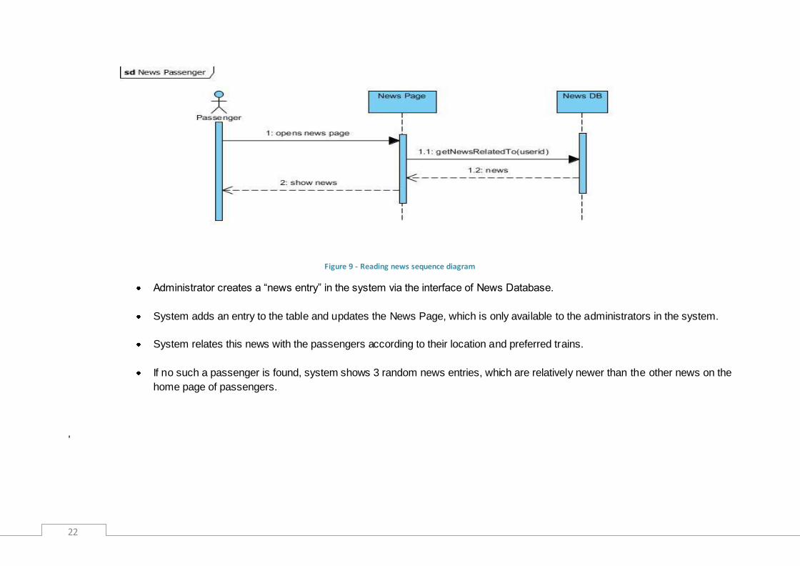
Figure 9 - Reading news sequence diagram
Administrator creates a “news entry” in the system via the interface of News Database.
System adds an entry to the table and updates the News Page, which is only available to the administrators in the system.
System relates this news with the passengers according to their location and preferred trains.
If no such a passenger is found, system shows 3 random news entries, which are relatively newer than the other news on the
home page of passengers.
,

23
5.2.8. Knowledge Database
Figure 10 - Knowledge database sequence diagram for admins

24
Figure 11 - Searching knowledge database sequence diagram
Passenger clicks “Sorun Giderme” button on the home page and the “Bilgi Sistemi” Page is opened.
Passenger clicks a related topic in the section “Sıkça Sorulan Sorular”, which are given as links in this page, to find a solution
to his question.
Passenger finds a similar question and clicks to it to see the details.
25
The chosen problem is displayed in a problem specific page.
If there isn‟t any related topic to his question, passenger returns to the “Bilgi Sistemi” Page and clicks “Diğerleri” link at the
end of this category.
The page of problems, which don‟t belong to any general topic is opened.
Passenger clicks to the similar problem if such a problem exists.
If there isn‟t any relevant question in this section, user returns to the “Bilgi Sistemi” Page and writes some keywords related
to his question into the text field reserved for search purpose and clicks “Ara” button.
The results are listed in a separate page if there is any.
System gives an information message “No matching question ” if there isn‟t any question related to these keywords.
This operation can also be repeated with other categories: “Genel Sorular ve Çözümler” or “Çözüm Bekleyen Sorular”.
26
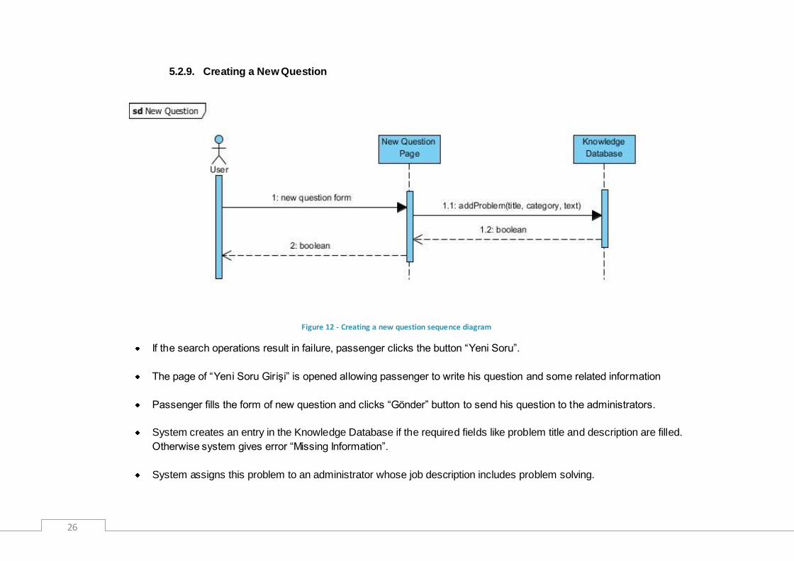
5.2.9. Creating a New Question
Figure 12 - Creating a new question sequence diagram
If the search operations result in failure, passenger clicks the button “Yeni Soru”.
The page of “Yeni Soru Girişi” is opened allowing passenger to write his question and some related information
Passenger fills the form of new question and clicks “Gönder” button to send his question to the administrators.
System creates an entry in the Knowledge Database if the required fields like problem title and description are filled.
Otherwise system gives error “Missing Information”.
System assigns this problem to an administrator whose job description includes problem solving.

27
5.2.10. Scheduling
Figure 13 - Scheduling sequence diagram

28
Figure 14 - Checking schedule sequence diagram for machinists
Administrator executes a search query to find proper Machinists who can drive a specific train in a specific time interval.
Administrator creates schedule tables via database interfaces.
System creates a schedule table which stores daily schedules of all machinists.
Machinists logs into home page to see his daily train schedule.
System relates these entries in the schedule table with the proper machinists and loads them to the home page of machinist.

29
5.3. Activity Diagrams
5.3.1. Login Activity Diagram
Figure 15 - Login activity diagram
The first activity in Figure 15 is to access login page. A decision then has to be made,
depending on having account. If there is no account to login the system, create new account.
If there is account to login to the system, user logs in. If user is valid, access profile, else
return access login page.

30
5.3.2. Train Monitoring Activity Diagram
Figure 16 - Train monitoring activity diagram
The first activity in Figure 16 is to access 'Tren Takip Sistemi' page. Then specify railway. A
decision then has to be made, depending on specifying train.
If a train is specified, system get information from GPS device and set all train fields.
If no train is specified, user specifies 'cikis yeri' and 'cikis saati'. After listing the trains
according to 'cikis yeri' and 'cikis saati', check there is one or more train.
If there is one train, system get information from GPS device and set all train fields.
If there are more than one train, you pass again 'specify train' decision.

31
5.3.3. Adding New Question Activity Diagram
Figure 17 - Adding new question activity diagram
The first activity in Figure 17 is to select 'Sorun Gönderme'. Then access 'Bilgi Sistemi' page.
After accesing page, user can choose one of the four options(FAQ Questions, Related
Question Page, Diğerleri Page, Search). If user does not found, he/she adds new question or
return to 'Bilgi Sistemi' page.

32
5.3.4. Best Path Activity Diagram
Figure 18 - Best path activity diagram
The first activity in Figure 18 is selects path and date. Then request best paths.
If there is no path, user returns selection path and date; else user chooses the desired paths and
saves.
33
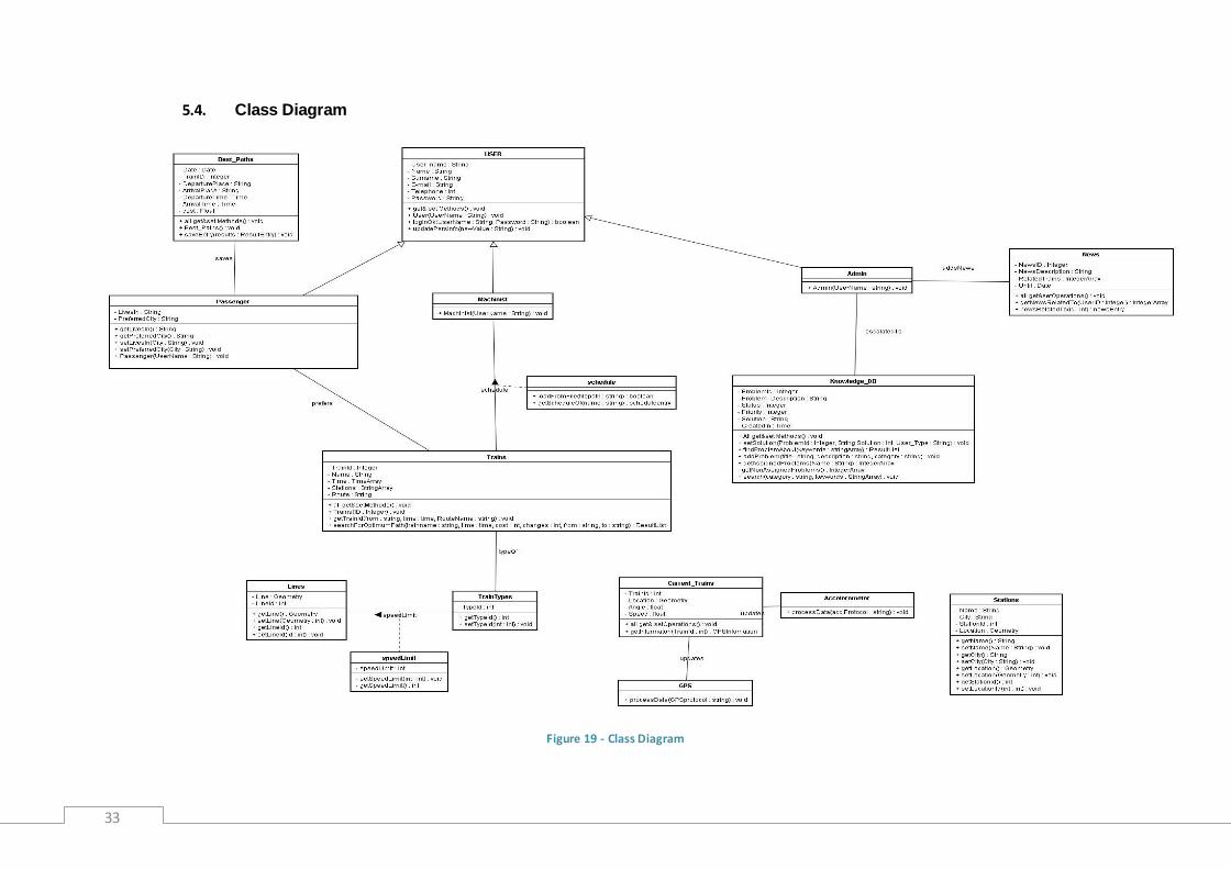
5.4. Class Diagram
Figure 19 - Class Diagram

34
User class is located in the user module. It is the parent class of the
individual user classes: passenger, machinist and administrator. It stores
all user members and provides get methods to access them. This class
also provides set methods to update user information received from
update form in the update information page. As pictured in the activity
diagrams Figure 2 and Figure 3, the methods updatePersInfo() and
LoginOk() are called and the database is updated accordingly.
Only passenger class has a private member apart from the other derived
classes administrator and machinist from base class user. It holds a
"lives_in" member in order to provide the information needed by
newsRelatedTo() funciton in the news class. Passenger class has a
relation with the trains, called prefers. This relation also provides
information for the NewsRelatedTo() method. After passenger logs into the
system, home page of the passenger will call this method and load the
related news for the passenger.
Machinist class does not hold any separate private member. This class
has a relation with trains class, called schedule. Schedule relation enables
the system to show the daily schedule of the machinist. After machinist
logs in, the related schedule entries in the database is shown in the home
page of the machinist. This is accomplished by getSchedule() method in
the associated class of schedule.
Schedules class is in the journey module. Administrators of the system
loads the daily schedule of all machinists everyday with a function
"loadFromFile(string)" in the associated class of schedule. The
administrators give a path to the schedules file in the "load schedule
page". This file is required to be a comma separated values (csv) file. The
function reads from the file and parses the data, then it drops the table
"schedules" if it exists. Then it creates the "schedules" table again and
adds new entries from the parsed data. In this way, the schedules table is
updated as illustrated in Figure 13.
News class is in the news module and provides methods to manage the
news table. Only the administrator of the system will be able to call the set
methods of this class. News class saves the news entities which are not
out of date. There will be an interface for the administrators to manage the
news table. The administrators will call clearNews() method daily and this
method checkes the news which are out of date and deletes them from the
news table. Administrator will also add new entries via this interface.
Stations class will provide methods to manage the stations in the
database. Stations table will only be used to hold the station names to
show them on the train monitoring and best path searching pages.

35
Lines class provides methods to get the lineId of the line segment which
the train is being on by supplying the position information of the train.
Geometry data type holds the line segment‟s coordinate informations.
TrainTypes class provides a method to get the locomotive type information
of a train. It also provides a set method which will be called only by an
administrator.
Trains class is one of the most important classes in the journey module.
This class provides an interface for the trains database.
SearchForOptimumPath method will be implemented in this class and via
this method, users will be able to query the trains and schedules table as
pictured in Figure 7. The required informations for this method are hold as
the members of the class. This method will first find all options from the
departure place to the destination place with a maximum number of 3 train
changes. To accomplish this, the function will trace the stations array, hold
by stations member, and find the matched entries for the departure place.
First the paths with no train changes will be found. Then for 1 change the
current train will be changed and the stations of that train will be traced.
After all trains are traversed, the function will return. The result list will be
modified according to the cost. After that the result list will be shown on the
home page of the user.
Current_Trains class provides two methods to set the class members and
to get them. When an object is initialized tThe members hold the
information which is fed from the GPS and accelerometer devices: the
speed, location and angle.
Knowledge database will provide users an interface to find related
problems about an issue, to add new problems (create a ticket) and to add
a solution to the system. setsolution() method will only be available to the
system administrators. All users will be able to use search() funciton to find
a related problem in a specific category. Another option for searching will
also be provided by findProblem() method, which finds any related
problem in the system without a category constraint. By addProblem()
method, users will be able to add a problem to the database. The
problems in the database will be assigned to the administrators by creating
an escalatedTo object. Then the administrators will be able to see them on
their home page. The sequence diagrams related to knowledge database
are shown in Figure 10, Figure 11, and Figure 12.
36
6. Data Design
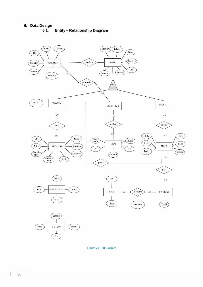
6.1. Entity – Relationship Diagram
Figure 20 - ER Diagram

37
6.2. Database Schemas
6.2.1. USER table
Field Type Null Foreign Key References
UserName (p.k.) Varchar(20) no no -
Name Varchar(20) no no -
Surname Varchar(20) no no -
Password Varchar(20) no no -
E-mail Varchar(30) no no -
Telephone Varchar(20) no no -
Birthday Date no no -
This table holds user information. Every user has to supply name, surname, password,
e-mail, and telephone information and select a username. Three tables (passengers,
administrators, machinists) extends from this table.
6.2.2. Passenger table
Field Type Null Foreign Key References
livesIn Varchar(20) no no -
User_name (p.k.) Varchar(20) No Yes USER
This table extended from USER table and every passenger has to supply the city he lives.
6.2.3. Best_Paths table
Field Type Null Foreign Key References
PathID (p.k.) Integer no no -
Date Date no no -
TrainID Integer no yes Trains
DeparturePlace Varchar(20) no no -
DepartureTime Time no no -
ArrivalPlace Varchar(20) no no -
ArrivalTime Time no no -
Cost Float no no -
UserID Varchar(20) no yes USER
This table contains information about a passenger‟s best path searches. After a user
searches some path, it is kept on that database and users may retrieve their past searches
38
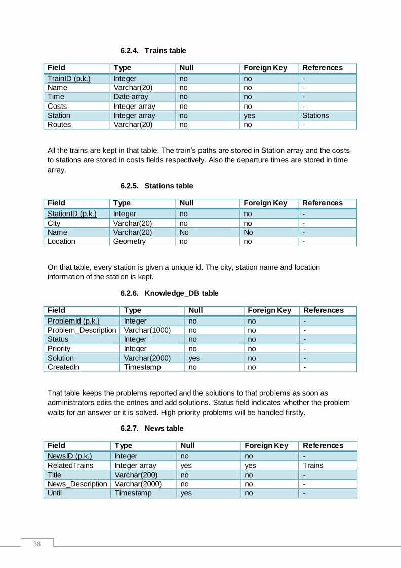
6.2.4. Trains table
Field Type Null Foreign Key References
TrainID (p.k.) Integer no no -
Name Varchar(20) no no -
Time Date array no no -
Costs Integer array no no -
Station Integer array no yes Stations
Routes Varchar(20) no no -
All the trains are kept in that table. The train‟s paths are stored in Station array and the costs
to stations are stored in costs fields respectively. Also the departure times are stored in time
array.
6.2.5. Stations table
Field Type Null Foreign Key References
StationID (p.k.) Integer no no -
City Varchar(20) no no -
Name Varchar(20) No No -
Location Geometry no no -
On that table, every station is given a unique id. The city, station name and location
information of the station is kept.
6.2.6. Knowledge_DB table
Field Type Null Foreign Key References
ProblemId (p.k.) Integer no no -
Problem_Description Varchar(1000) no no -
Status Integer no no -
Priority Integer no no -
Solution Varchar(2000) yes no -
CreatedIn Timestamp no no -
That table keeps the problems reported and the solutions to that problems as soon as
administrators edits the entries and add solutions. Status field indicates whether the problem
waits for an answer or it is solved. High priority problems will be handled firstly.
6.2.7. News table
Field Type Null Foreign Key References
NewsID (p.k.) Integer no no -
RelatedTrains Integer array yes yes Trains
Title Varchar(200) no no -
News_Description Varchar(2000) no no -
Until Timestamp yes no -

39
This table holds data about some special offers such as a cut on ticket prices. They will be
showed to passengers as advertisements. Also in that table, the delay or cancellation
information will be hold.
6.2.8. Traintypes table
Field Type Null Foreign Key References
TypeID char no no -
This table contains typeIDs and will be joined with trains database.
6.2.9. Lines table
Field Type Null Foreign Key References
LineID (p.k.) Integer no no -
Line Geometry no no -
The geospatial data will be hold on that table line by line. Every line will be given a unique id
number to decrease the processing load while querying.
6.2.10. Currenttrains table
Field Type Null Foreign Key References
TrainID Integer no yes Trains
Location Geometry no no -
Speed Integer no no -
Angle Integer no no -
The moving trains will be hold on that database. The location, speed and horizontal angle
information will also be stored.

40
7. Interface Design
7.1. User Interfaces
7.1.1. Registration Interface
On registration page, the user will be asked to supply some personal information and also he
will be asked to supply a username – password combination. If the users marks the
checkbox, he will receive e-mails about promotion news.
7.1.2. Login Interface
41
On login page, user types his username and password, and then selects the user type from
the combo box. When user clicks the “Tamam” button, the supplied information is checked
and the user will be given authorization if they are correct. Also on that page, not registered
users may follow the “Yeni Kullanıcı” link to register to the system.
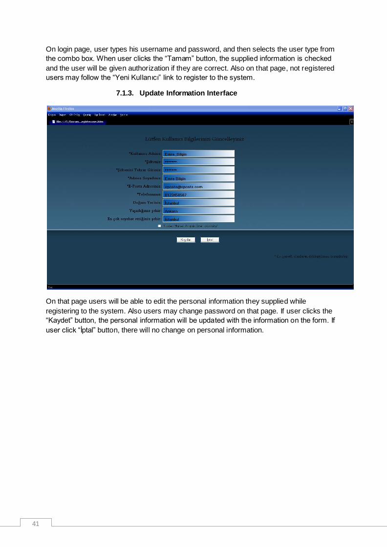
7.1.3. Update Information Interface
On that page users will be able to edit the personal information they supplied while
registering to the system. Also users may change password on that page. If user clicks the
“Kaydet” button, the personal information will be updated with the information on the form. If
user click “İptal” button, there will no change on personal information.

42
7.1.4. Knowledge Database Interface
On knowledge database and help page, there are many links grouped under four sections:
Frequently Asked Questions
General Questions & Answers
Questions Waiting Answers
Useful Links

43
A user may use the search boxes to search some keywords on help pages. Also a user may
create a new problem entry by clicking the “Yeni Kayıt” button.
When the user clicks the “Yeni Kayıt” button, a form page displayed. User is required to type
a problem title and description and also select the problem category.

44
7.1.5. Optimum Cost / Optimum Time Search Interface
A user may search for an optimum cost / optimum time train. User may choose the
destination place, arrival place, date and time interval, maximum price, maximum number of
train changes and maximum journey time and system shows the corresponding trains.

45
Also the user‟s search histories are kept and a user may see his search histories anytime he
wants.
7.1.6. Passenger Tracking Interface
On the left side of that page, a passenger may see the position of a train he selects on the
map. On the right, the details about selected train are displayed.

46
7.1.7. Machinist Tracking Interface
A machinist may see only the positions of the trains on the same railway route. On the right
half of the page, the position, next station, distance to next station, expected arrival time,
expected remaining time to arrival, expected departure time, current speed, the speed limit
and the distance to the next light are displayed. Also the current railway route, train id,
departure city information will be on the interface. In some cases, if there is a warning, it is
displayed on the middle frame of the right half of the page.

47
If a machinist exceeds the speed limit, an appropriate warning will be displayed and it will be
written with red color to get the attention of the machinist. This frame will also be used when
departure time comes and warns the machinist to move. Another use of that warning frame is
while getting nearer to a station or control point, telling the machinist to slow.
7.1.8. Machinist Task Interface
Machinists can see their task schedules on that page. On the list, the train ids, regions,
departure and arrival cities and times are displayed.

48
8. System Design
8.1. User Information Security
In the Login Page the users will enter their username and password. The system will
check the username and password from the database. The passwords of the users
will be kept in the database in an encrypted form. Login Page and the other pages of
the system will be implemented using PHP technology . The passwords of the
users will be encrypted and then kept in the database to ensure security. PHP
provides its own built-in hashing functions for encryption. The different interfaces for
different users will be provided by PHP. After the user logs in, the system will check
the user type and display the corresponding interface.
User passwords must be stored safely in the database. So, we must store password
encrypted in database. We use MD5 function. "The MD5 message-digest algorithm
takes as input a message of arbitrary length and produces as output a 128-bit
"fingerprint" or "message digest" of the input. The MD5 algorithm is intended for
digital signature applications, where a large file must be "compressed" in a secure
manner before being encrypted with a private (secret) key under a public-key
cryptosystem such as RSA.
The MD5 algorithm is designed to be quite fast on 32-bit machines. In addition, the
MD5 algorithm does not require any large substitution tables; the algorithm can be
coded quite compactly. MD5 function is also defined in PHP.
8.2. Optimum Train Suggestion System
In the Home Page the passengers will plan their travels. They will search for the
possible paths for their desired destination stations, departure stations and date. After
selecting the departure and destination stations, 3 more drop down menus will
appear. The user will choose the date and the train type. After the stations chosen,
the system will show new drop down menus with the help of JavaScript
technology. The OTTS (Optimum Train Suggestion System) will determine the most
suitable selections with the help of a minimum time/cost finding algorithm. The user
will be able to sort the results according to travel time, cost, train type or number of
changes. The system will do this by adding a final database query to sort these
results according to the given entity. The result can be saved by the users to the
personal page. The result appears as a link on the personal page. It will be kept in the
user table of the database.
8.3. Intelligent Machinist Assignment
The machinists will check their daily schedule from Home Page. Intelligent Machinist
Assignment will assign machinist to appropriate machines. The Brevets of machinists
will be kept in the database. The system will match the machines with the machinist
having the desired brevet and then choose one machinist to assign that machine.
8.4. Personal Information
In the Personal Page the users will be able to update their personal information. The
system will fetch the information of the users from the database and fill the form with
corresponding information. After editing, the system will update the information of

49
users in the database. And also travel history of users will be kept in the database
and can be shown from this page.
8.5. Live Train Monitoring
In the Live Train Monitoring Page the users will be able to keep track of the trains on
the map of the railways. This page will be implemented by using JSP technology .
It ensures to use Java functions and facilities in the web page. Since the main system
functions will be implemented in Java, JSP is a better solution and more suitable for
us to use. The map for the Live Train Monitoring will be drawn using Autocad Map 3D
and then it will be processed by some Java functions with GPS data. Java program
will mark the positions of the trains on the map looking at the GPS data. The resulting
map will have the positions of the trains and stations and it will be shown in the Live
Train Monitoring Page. All of the users will be able to see the positions of the trains
and also some information about the trains. The position and the other information will
be updated periodically. The system will take the new coordinates and other
information from GPS and update the result.
The machinists will also see the information and position of their own train and the
other trains on the same line. On the machinist panel, the speed limit and the
distance to the next station will also be shown. The speed limits for specific areas will
be stored in the database. The system will check the current speed limit from the
database with the position information and it will calculate the distance to the next
station.
8.6. Emergency Situations
If an emergency situation occurs, the machinists will be able to push a button to warn
the admin about the situation and send critical information to the admin. If a signal is
received from the accelerometer, an emergency signal will be sent to admin and
nearest control point automatically. The system on the machinist panel will process
the signal coming from the accelerometer and send emergency signal.
8.7. Railway Map
The reason a new railway map is drawn with Autocad Map 3D is to see the system
features and test the system more effectively enough on a suitable map. The railways
in Turkey are not very complex and complicated. For every travel between cities there
is only one possible path. We want our system to be useful in the future and it will be
adaptable to any railway system. So, the current railway map of Turkey is not enough
for our project. With this map the OTSS (Optimum Train Suggestion System)
becomes useless. So, we will draw our own railway map and simulate the system on
this map. Autocad Map 3D will be used to draw a new railway map. The map will only
cover some part of Turkey and it will have many connections. It will be possible to
select at least two different options from one city to another. Smaller stations will be
connected to big cities with one railway and slower trains will be used.
8.8. Contact Information
In the Contact Page the users will be able to see the addresses, e-mails, phone
number of stations, points to buy tickets, call centers. The user will be able to see the
position of these places on a map. Google Maps gadget will be used at this point.

50
Google Maps is a basic web mapping service application and technology provided by
Google. It offers street maps, a route planner for traveling by foot, car, or public
transport and an urban business locator for numerous countries around the world.
There is only one problem with Google Maps. Since Google Maps is only free of
charge for non-commercial use, it limits the number of requests in a certain time
interval for a user. But since the gadget is not directly system related, the limit will
only apply to the system users.
The users will be able to send e-mail directly by clicking on the e-mail addresses. For
this purpose there is no need to use any extra application. With some simple HTML
code this can be done.
8.9. Knowledge Database
In the Help Page the users will be able to search in a database of topics from
database called Knowledge Database. It‟s mainly an issue tracking system. An issue
tracking system is a computer software package that manages and maintains lists of
issues, as needed by an organization. Issue tracking systems are commonly used in
an organization's customer support call center to create, update, and resolve reported
customer issues, or even issues reported by that organization's other employees. An
issue tracking system often also contains a knowledge base containing information on
each customer, resolutions to common problems, and other such data.
Our system will provide passengers a knowledge database which allows them to
solve their problem without calling the TCDD staff or sending a mail to them. If they
can‟t find any solution, they will create a ticket. These tickets must be managed in a
professional way.
For this purpose we want to use an issue tracking system. With this system the
administrators will be able to get new tickets from the passengers, assign them to the
related persons and escalate them to the more experienced administrators. In this
system they will also have a time restriction. All tickets will be solved in a particular
time interval.
Instead of implementing such a complicated issue tracking system, we will integrate
the application “JTrac” to our system. JTrac is an open source and highly
customizable issue-tracking web-application written in Java. JTrac has many of the
features of a standard issue-tracking application such as support for file-attachments
and e-mail integration that we would like to integrate to our system. JTrac offers many
customization options, especially in the areas of workflow and field-level permissions.
We will take its most useful and basic parts ant let them work in our background
environment.
8.10. Database
As Database Management System, MySQL will be used. It‟s an open source software
licensed under the terms of GNU GPL.

51
8.11. Webpage Design
We will need Apache Tomcat as a servlet container to work with JSP pages. This is
an open source software developed by Apache Software Foundation. Apache Tomcat
provides a pure Java HTTP web server environment for Java code to run.
For the search in the web site we will use Google search. With some HTML code ,
the search string is sent to Google from the web page and the search scope is
minimized to the current web site only.

52
9. Project Schedule
The project schedule is illustrated on the following Gantt chart .

53

54
10.References
[1] Savronik tren bilgi sistemi. (n.d.). Retrieved from http://www.trenbilgisistemi.net/
[2] Tcdd bilet satış & rezervasyon sistemi. (n.d.). Retrieved from https://etcdd.tcdd.gov.tr/
[3] Ihr mobilitätsportal für reisen, bahn, urlaub, hotels, städtereisen und mietwagen . (n.d.). Retrieved
from http://www.bahn.de/p/view/index.shtml
[4] Subversion. (n.d.). Retrieved from http://subversion.tigris.org/
[5] Autocad map 3d mapping software. (n.d.). Retrieved from
http://usa.autodesk.com/adsk/servlet/pc/index?id=13818317&siteID=123112
[6] Windows 7 home. (n.d.). Retrieved from http://windows.microsoft.com/en-
US/windows7/products/home?os=winxp
[7] Mysql : the world's most popular open source database. (n.d.). Retrieved from
http://www.mysql.com/
[8] Welcome! - the apache http server project. (n.d.). Retrieved from http://httpd.apache.org/
[9] Mapguide project home | mapguide open source. (n.d.). Retrieved from
http://mapguide.osgeo.org/
[10] Developer resources for java technology. (n.d.). Retrieved from http://java.sun.com/
[11] Apache tomcat - welcome!. (n.d.). Retrieved from http://tomcat.apache.org/
[12] NetBeans Foundation. (2003). Welcome to netbeans. Retrieved from http://netbeans.org/
[13] The PHPGroup (2001, dec 11). Php hypertext preprocessor. Retrieved from
http://php.net/index.php
[14] W3 Schools. (2000). PHP md5() function. Retrieved from
http://www.w3schools.com/php/func_string_md5.asp
[15] SunMicrosystems. (2002, March 3). Java server pages technology. Retrieved from
http://java.sun.com/products/jsp/
[16] Google, . (2008). Google maps api. Retrieved from http://code.google.com/intl/tr-TR/apis/maps/
[17] JTrac. (2008). Jtrac features. Retrieved from
http://www.jtrac.info/doc/html/features.html/Issue_tracking_system
[18] Taylor, Dave. (2002). How can I add a search box. Retrieved from
http://www.askdavetaylor.com/how_can_i_add_a_google_search_box_to_my_web_site.html
[19] Gnatt Project Team, . (2003). Gnatt project home. Retrieved from http://www.ganttproject.biz/

55
[20] Comma-separated values - wikipedia, the free encyclopedia. (n.d.). Retrieved from
http://en.wikipedia.org/wiki/Comma-separated_values
[21] Nmea 0183 - wikipedia, the free encyclopedia. (n.d.). Retrieved from
http://en.wikipedia.org/wiki/NMEA_0183