destination tag routing techniques based on a state model
TRANSCRIPT

Purdue UniversityPurdue e-PubsDepartment of Electrical and ComputerEngineering Technical Reports
Department of Electrical and ComputerEngineering
10-1-1987
Destination Tag Routing Techniques Based on aState Model for the IADM NetworkDarwen RauPurdue University
Jose A. B. FortesPurdue University
Howard Jay SiegelSupercomputing Research Center
Follow this and additional works at: https://docs.lib.purdue.edu/ecetr
This document has been made available through Purdue e-Pubs, a service of the Purdue University Libraries. Please contact [email protected] foradditional information.
Rau, Darwen; Fortes, Jose A. B.; and Siegel, Howard Jay, "Destination Tag Routing Techniques Based on a State Model for the IADMNetwork" (1987). Department of Electrical and Computer Engineering Technical Reports. Paper 580.https://docs.lib.purdue.edu/ecetr/580

/
Destination Tag Routing Techniques Based on a State Model for the IADM Network
Darwen Rau Jose A. B. Fortes Howard Jay Siegel
TR-EE 87-39 October 1987
School of Electrical EngineeringPurdue UniversityWest Lafayette, Indiana 47907

Destination Tag Routing Techniques Based on a State Modelfor the IADM Network1
Darwen Rau and Jose A. B. Fortes School of Electrical Engineering
Purdue University West Lafayette, IN 47907
Howard Jay Siegel Supercomputing Research Center
4380 Forbes Blvd. Lanham, MD 20706
ABSTRACT
A "state model" is proposed for solving the problem of routing and rerouting messages in the Inverse Augmented Data Manipulator (IADM) network. Using this model, necessary and sufficient conditions for the reroutability of messages are established, and then destination tag schemes are derived. These schemes are simpler, more efficient and require less complex hardware than previously proposed routing schemes. Two destination tag schemes are proposed. For one of the schemes, rerouting is totally transparent to the sender of the message and any blocked link of a given type can be avoided. Compared with previous works that deal with the same type of blockage, the timeXspace complexity is reduced from O(logiV) to 0(1). For the other scheme, rerouting is possible for any type of link blockage. A universal rerouting algorithm is constructed based on the second scheme, which finds a blockage-free path for any combination of multiple blockages if there exists such a path, and indicates absence of such a path if there exists none. In addition, the state model is used to derive constructively a lower bound on the number of subgraphs which are isomorphic to the Indirect Binary N-Cube network in the IADM network. This knowledge can be used to characterize properties of the IADM networks and for permutation routing in the IADM networks.
Index terms - cube network, data manipulator network, destination-tag routing, fault tolerance, interconnection network, multiprocessor, parallel processing, state model.^This research was supported in part by the National Science Foundation under Grant DC1-8419745, by the
Innovative Science and Technology Office of the Strategic Defense Initiative Organization and was administered through the Office of Naval Research under contract No. 00014-85-k-0588, and by the Supercomputing Research Center under contract MDA904-85-C-5027.

2 -
1. Introduction
This paper discusses novel and efficient techniques for routing and rerout
ing messages in the Inverse Augmented Data Manipulator (IADM) network [9].
These results are based on a new approach, the "state model," which character
izes and correlates the topologies of the IADM and Indirect binary n-cube net
works, and leads to efficient exploitation of the redundancy available in the
IADM network.
Considerable research has been dedicated to the design of multistage inter
connection networks for multiprocessor systems. The class of data manipulator
networks] introduced in [3], includes, among others, the Augmented Data Mani
pulator (ADM) network [17], the IADM network [9] and the Gamma network
[13][14]. The IADM network and the ADM network differ only in that the input
side of one of them corresponds to the output side of the other and vice versa,.
The Gamma and the IADM networks are topologically equivalent; however,
they use switches of different types. Each 3X3 crossbar switch used in the
Gamma network can connect simultaneously all three inputs to all three out
puts whereas each switch used in the IADM network can connect only one of its
three inputs to one or more of its three outputs. The main interest of this
paper is the study of the IADM network; both the one-to-one and permutation
routings are considered. The schemes proposed for routing and rerouting mes
sages in the IADM network are also applicable to the Gamma network.
Perhaps the most popular class of multistage networks is the multistage
cube-type networks such as the Indirect Binary N-Cube [15], Omega [6], Baseline
[20], Generalized Cube [18], STARAN flip [2] and a special case of SW-Banyan
[4] networks. Among the main advantages of these networks are their very
efficient destination tag routing schemes, partitionability, 0(N\og2N) cost and
- 3 -
ability to pass useful permutations [16]. Some results of this paper are based on
characteristics of the Indirect Binary N-Cube network (hereon referred to as the
ICube network). Since the cube-type networks mentioned above are all topologi
cally equivalent [16][17][20][21], the results in this paper are also relevant to any
of them.
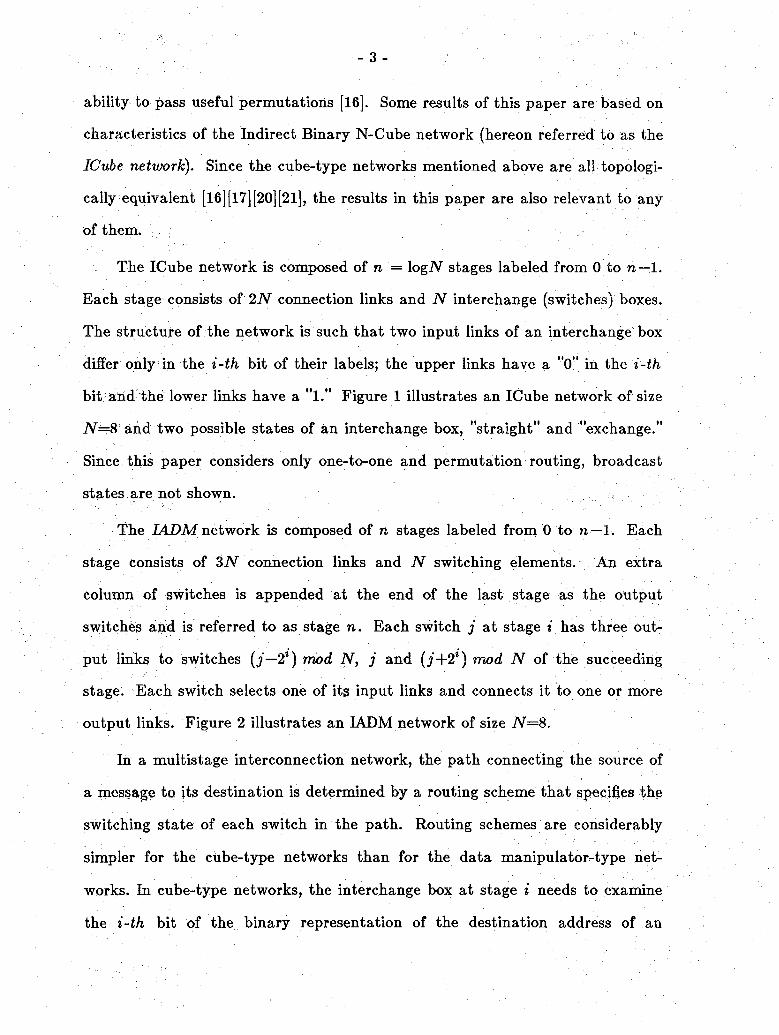
The ICube network is composed of n = logiV stages labeled from 0 to n — 1.
Each stage consists of 2JV connection links and N interchange (switches) boxes.
The structure of the network is such that two input links of an interchange box
differ only in the i-th bit of their labels; the upper links have a "0" in the i-th
bit and the lower links have a "l." Figure 1 illustrates an ICube network of size
IV=8 and two possible states of an interchange box, "straight" and "exchange."
Since this paper considers only one-to-one and permutation routing, broadcast
states are not shown.
The IADM network is composed of n stages labeled from 0 to n■—1. Each
stage consists of 3N connection links and N switching elements. An extra
column of switches is appended at the end of the last stage as the output
switches atid is referred to as stage n. Each switch j at stage * has three out
put links to switches (j—2*) mod N, j and (j+2l) mod N of the succeeding
stage. Each switch selects one of its input links and connects it to one or more
output links. Figure 2 illustrates an IADM network of size N=8.
In a multistage interconnection network, the path connecting the source of
a message to its destination is determined by a routing scheme that specifies the
switching state of each switch in the path. Routing schemes are considerably
simpler for the cube-type networks than for the data manipulator-type net
works. In cube-type networks, the interchange box at stage i needs to examine
the i-th bit of the binary representation of the destination address of an

- 4 -
incoming message. If the i-th bit is 0, then the upper output of the box is
taken. If the i-th bit is 1, the lower output of the box is taken. These schemes
are known as destination tag routing schemes [6] and are extremely efficient and
simple to implement. Unlike cube-type networks, in the IADM and other data
manipulator-type networks there are several paths between any source s and
destination d (s=fid) and each switching element has at least three switching
states. Previously proposed routing schemes [9] [10] [13] for the IADM network
can be thought of as distance tag schemes', that is, they require calculation of
the distance from source to destination in order to generate routing and rerout
ing tags. The rerouting schemes in these works are basically finding an alter
nate representation, which specifies an alternate routing path, for the distance.
McMillen and Siegel [9] proposed three dynamic rerouting techniques for
the IADM network for avoiding faulty or blocked ±2* (nonstraight) links. The
first and the second schemes require that switches be capable of performing
two’s complement and +2* addition operations, respectively. The third scheme
requires one extra tag bit which is dynamically updated as the message pro
pagates toward the destination. In [10], the work of [9] was expanded, and a
single-stage look-ahead scheme was proposed to avoid certain type of straight
link faults. This improved scheme also requires two’s complement operations.♦
Parker and Raghavendra [13] used redundant number representation and
proposed an algorithm capable of finding all routing paths, which, effectively,
are the redundant number representations for the distance between the source
and the destination. Because of the complexity of the algorithm, the cost of
computation is prohibitively large so that it is infeasible to implement the algo
rithm in order to achieve dynamic routing [19]. In addition, although the algo
rithm can generate all routing tags for any distance, there is no specific work on

- 5 -
rerouting schemes in [13] [14].
Lee and Lee [7] proposed signed bit difference tag and destination tag local
control algorithms for the ADM and IADM networks that require no computa
tion for the distance between the source and the destination. But their local
control algorithms can only find one routing path for each source and destina
tion pair. If the need for rerouting arises, they still resort to the distance tag
schemes to find alternate paths.
Past research has shown interesting relationships between data manipula
tor and cube-type networks. For example, because it is possible to embed the
Generalized Cube network in the ADM network [1][17], the set of interconnec
tions implementable by the ADM network is a superset of that of the General
ized Cube network. This fact and the existence of multiple paths between any
source s and destination d (s^d) in the ADM network suggests that the ADM
network can be thought of as a fault-tolerant Generalized Cube network.
Analogously, the IADM network can be regarded as a fault-tolerant ICube net
work2. Since the permutations realizable by cube-type networks are well stu
died, the identification of possible embeddings of the ICube network in the
IADM network can help characterize the permutation capabilities of this net
work. A contribution to the precise understanding of these notions is made in
this paper; it consists of the identification of a large number of distinct sub
graphs of the IADM network that are isomorphic to the ICube network.
Section % of this paper introduces a state model to describe and correlate
topologies of the ICube network and the IADM network. Necessary and2 •While topologically equivalent, the ICube and Generalized Cube I/O ports are addressed so that their inter-relationship is the same as that of the IADM and ADM network, i.e. the input and output sides are interchanged.

- 6 -
sufficient conditions to perform rerouting in the IADM network are derived in
Section 3 . In Section 4 two routing and rerouting schemes are proposed based
on the theory developed in Section 3, together with a discussion of their merits
and implementation considerations. A universal rerouting algorithm is proposed
in Section 4, which can deal with any combination of multiple link blockages.
A class of subgraphs in the IADM network that are isomorphic to the ICube
network are identified in Section 6, and it is shown how to reconfigure the
IADM network under certain link faults to pass the cube-admissible permuta
tions. Finally, Section 7 summarizes the results presented in this paper.
2. State Model Descriptions for the ICube and IADM Networks
Multistage networks can be modeled as graphs by treating interchange
boxes (also called switching elements) and links of the network as nodes and
edges of the graph, respectively. Another equivalent graph model [l] [8] results if
interchange boxes are associated with edges, and links with nodes. Both models
are exemplified in Figures 1 and 3 for the ICube network. The IADM network is
shown in Figure 2 according to the first model. The design of switches based on
both models is discussed in [ll]. Clearly, the ICube network in Figure 3 can be
regarded as being a subgraph of the IADM network in Figure 2. Henceforth,
the second model is always assumed when referring to the ICube network (i.e.
Figure 2) and the first model is assumed when dealing with the IADM network.
With respect to these graph models, the nodes and the edges of the graph
refer to the switches and the links of the networks, respectively. The number of
switches at each stage of a network is denoted N and n = log2iV refers to the
number of stages. The switches of each stage are labeled from 0 to N—1 from
the top to the bottom. Any integer j has a binary representation

- 7 -
joil ' • • ire-i, where ire-i is the most significant bit and n denotes the number
of bits. Tfie notation jp/q means the bits of j starting at jp and ending at jq,
where p < q. Bit j) is l’s complement of bit j). Throughout this paper, j and
j+a, where a is some constant, are reserved to represent labels of switches.
Also modulo N arithmetic is assumed, e.g. j+a implies (j+a) mod N. The
notation iE#,- is used to indicate that a switch j belongs to stage i and
(jESi , j"(zSi+1) is used to represent a link at stage i joining j ES1,- and j'(zSi+1.
A sequence of switches of contiguous stages (jESi , j ESi+l , • • • , j' ESi+k) is
used to represent a path from /e>S,- to j ESi+k.
Notation and terminology required for the characterization of network
topologies and destination tag routing schemes are introduced next. A switch j
of stage i is an even,- switch if ^ = 0 and an odd,- switch if jj- = 1. Figure 2
identifies even,- and odd,- switches at different stages of the IADM network of
size N=8. Define the functions AC,- and AC,- that represent connection links at
stage i as
ACi(M)
q if j is an even,- switch and i,-=0, or if j is an odd,- switch and t,- =1
—2* if j is an odd,- switch and f,-=0 +2* if j is an even,- switch and i,-=l
V
AC-(M-) = -A ct.(M)
Also, define the functions C,-(y,^,-) = j + AC,-(j,f,-) and
Ci(j)U) — j + AC,-(j,^,-). These definitions imply the following lemma of funda
mental importance to the results of this paper.
Lemma 2J.
Jo/i—3i+\/n—1

- 8 -
for some value of gJ+1/w_1 which depends on j and t,-.
Proof: If j is an even,- switch and i,- = 0, then Ct-(./,£,•) = C^j,^) = j. If j is
an oddi switch and t,- = 1, then C^j,^) = = j. If j is an odd{ switch
and = 0, then C,•(,/,£,•) results from subtracting 1 from j,-. Since j is an odd,-
switch, j} — 1, no borrow is generated and all remaining bits of j are
unchanged; however, (?,•(/,£,•) adds 1 to j,-, changing the i-th bit to 0 and alter
ing some of the bits in positions *+1, . . . ,n— 1 due to carry propagation. Simi
lar reasoning applies when j is an even,- switch and ti — 1. □
The notation and terminology just introduced can now be used to describe
the networks of interest in this paper. The following description for a network
in terms of AC,-, AC,-, C, and C, is called the network state model.
The ICube network is composed of n stages labeled from 0 to n—1. Each
stage consists of 2N links and N switches. An extra column of switches is
appended at the end of the last stage as the output switches (Figure 3) and is
denoted Sn. A switch j&S,- is connected to switches C,-(j,i,-)(ES,-+1, for
0 < i < n—1, 0 < j < AT—1, and f,- =0 or ^ = 1. When using destination
tags, switch j)£<?,- routes a message to switch C^j,di)ESi+l where di is the i-th
bit of the address of the message destination.
The IADM network is composed of n stages labeled from 0 to n— 1. Each
stage consists of a column of N switches and 3N connection links. An extra
column of switches is appended at the end of the last stage as the output
switches and is denoted Sn. A switch j&S1,- is connected to switches
Ci(j>ti)£Si+i and CitiA)£Si+1 f°r 0 <'* < n— 1, 0 < j < N—1, and t+ = 0 or
^ = 1. In other words, three links connect a switch to the switches (j—2l),

- 9 -
j and (y+2*) at stage t+1. Sometimes +2* and —2* are used to represent links
(i£<% , (i+2l)£5,+1) and (./&% , {j— 2*)£-S,,-+1), respectively. The terms a
straight link refers to link (j^Si , j£Si+1) and a nonstraight link refers to links
±2\
According to the model, two types of switches, even,- and odd,-, are required
in the IADM and ICube networks. Figure 4 illustrates the connection links of a
pair of even,- and odd,- switches for an ICube and an IADM network of size
N—8. The AC,- function describes the ICube connections. For the IADM net
work, the connection links can be described by the union of the functions ACi
and AC,-. In practice, even,- and odd,- switches can be identical and easily pro
grammed (at power-up or system configuration time) to behave differently.
There are two possible routing behaviors (or states) for each switch in an
IADM network. A switch is said to be in state C if the routing is decided in
accordance with the function C,-(y,t,-) and it is in the state C if the function
CdjA) applies. On the whole, the link on which a message is routed depends
on whether the switch is an even,- or odd,- switch, in state C or C, and the
value of tag bit £,-. Also the term state of the network is used to denote collec
tively the states of all switches in the network.
The notion of switch state is only conceptual; it can be implemented by
designing the switches with actual logic states as well as by using tags with n
added bits specifying the states of the switches on the routing path. In Section
4, these and other aspects of the actual implementation of the proposed
schemes are discussed in detail.
- 10 -
3. Theory behind the State-Based Destination Tag Routing Schemes
Based on the framework developed in Section 2, routing problems in the
IADM network are now examined. It is clear that when every switch in the
IADM network is in state C, the IADM network behaves like an ICube network
and, therefore, the destination address d0/n-i can be used as a routing tag, i.e.
i,- = dj. More generally, the following theorem can be proven.
Theorem 3.1 Let d — d0/n_i be the destination in the IADM network to which
a message is to be sent. Then t = d0/n_1 is the unique destination routing tag
to the destination d regardless of state of the IADM network.
Proof: Consider an arbitrary tag / o/»—l anc* assume that the IADM network is
in an arbitrary state. Let i0/n-i = / o/n-i- Then each switch will route the
incoming message to either or C'l(j’,/t). From Lemma 2.1, it can be
reasoned by induction that, at stage i, (C',-(^,/*))0/* = (C7f(j,/t))0/i = f o/ii at
the last stage, C're_1(j,/n_1) = Cn_1(y,/n_1) = /0/n_1. Thus the address of
the destination of the message is the same as the routing tag. This proves both
the validity and the uniqueness of dQ/n_1 as a routing tag. □
It is implicit in the reasoning underlying Theorem 3.1 that any link on a
given path results from the appropriate choice of the state of the corresponding
switch, i.e. the use of "link". results from setting jESi to state C and
the use of "link" Aresults from setting jES^ to state C. Thus, given a
path to the destination d, there is at least one network state for which the use
of d as the destination tag results in the routing of a message through that
path.
The implication of Theorem 3.1 is that the use of a state model for the
IADM network reduces the problem of finding alternate routing paths to that of

- n -
controlling the states of the switches in the network. Capitalizing on this idea,
the following theorems show how alternate routing paths can be found in order
to evade blockages in the network. A straight link blockage occurs if a straight
link on the routing path is faulty or busy. A nonstraight link blockage is defined
analogously. The third type of blockage, called double nonstraight link blockage,
occurs if both nonstraight output links of a switch in the routing path are
faulty or busy. A switch blockage occurs if the switch itself is busy or faulty. A
switch blockage has the same effect as blocking all of the switch’s input links
and can be transformed into a link blockages problem accordingly. The discus
sion on rerouting in this paper is concerned only with link blockages.
Theorem 3.2 In the IADM network, a change of the state of switch j^Si results
in a different routing path to a destination d if and only if a nonstraight output
link of j is used on the original routing path to d. Moreover, the other non
straight output link of j is used on the new path.
Proof: Changing the state of j implies that the "link" AC^(j,t,) is used instead
of or vice versa. However, if = 0 then A<7t(j,£t) = 0 (i.e.
both use a straight link) and vice versa. □
With regard to the rerouting schemes proposed in this paper, the implica
tions of Theorem 3.2 are twofold. First, the "if" part of the theorem implies
that dynamic rerouting for a nonstraight link blockage can be achieved by
changing the state of the switch whose output is the nonstraight link, which is
equivalent to rerouting the message through the oppositely signed nonstraight
link connected to the same switch. Thus, the same subset of destinations is
reachable from the two switches whose input links are the two oppositely signed
nonstraight links. Second, the "only if" part of the theorem implies that
dynamic rerouting for a straight link blockage is impossible. This is true in
- 12 -
general since every routing path in the IADM network can be the result of set
ting the network to some state. Moreover, if a path from stage i to stage *
consists of all straight links connecting jESi and jESi+1, i' < i <. t", then there
exist no alternate routing paths from jES^ to jES-" for otherwise there would
exist an alternate routing path branching from jESj and ending at the destina
tion. The only resort, if any at all, to bypass the straight link blockage is to
backtrack to a switch connected to a nonstraight link on the routing path at
some preceding stage and to reroute from that switch. It remains to show that
an alternate routing path always exists, provided that such a nonstraight link
exists. In fact, the existence of an alternate routing path partly results from
Theorem 3.2, as stated in the next theorem. Figure 5 illustrates the situation in
Theorem 3.3.
Theorem 3.3 Consider a routing path in the IADM network to a destination d
that contains a blocked straight link at stage i. There exists at least one net
work state which results in an alternate routing path that avoids the same
straight link blockage at stage i if and only if the original routing path to d
contains a nonstraight link at stage i—k for some k, i > k > 0.
Proof: See Appendix Al. □
Previous work [7] [9] [13] implies only the "if" part of the theorem, i.e. the
possibility of using nonstraight link of opposite sign in order to reroute a mes
sage in the case of a nonstraight link failure. However, the "only if" part of the
theorem also implies that, in addition, it is not possible to devise a new rerout
ing scheme capable of avoiding a backtracking (or look-ahead) mechanism in
order to deal with straight link blockages.
From Theorem 3.2, (for a given source/destination pair) if the straight out
put link of a switch is on some routing path, both nonstraight output links of

- 13 -
the switch cannot be used for routing; if one of the nonstraight output links of
a switch is on some routing path, the other nonstraight link of the switch is also
on another routing path and the straight link of the switch cannot be used for
routing. So for a given switch, the output link blockages that affect paths from
a given source to a given destination can only be (a) a nonstraight link block
age, (b) a straight link blockage or (c) the double nonstraight link blockage.3
Theorem 3*2 can be used to avoid case (a) a nonstraight link blockage and
Theorem 3.3j case (b), a straight link blockage. If case (c) occurs, then Theorem
3,2 cannot be used to find a rerouting path. A backtracking scheme proposed
later in Corollary 4.2 based on Theorem 3.3 can be adapted to overcome this
type of blockage. The adapted backtracking scheme is based oh Theorem 3.4,
which is illustrated in Figure 6.
Theorem 3.4 Consider a routing path in the IADM network to a destination d
that contains a switch at stage i whose both nonstraight output links are
blocked. There exists at least one network state which results in an alternate
routing path that avoids the same blocked nonstraight links at stage i if and
only if the original routing path to d contains a nonstraight link at stage i —k
for some fc, * > k > 0.
Proof: See Appendix Al. □
Physically it is possible to have any combination of blockages of the output links of agiven switch. However, the possible routing paths for a given source/destination pair caii be affected by either a straight link blockage or a double nonstraight link blockage in a given switch but never both types of blockage.

14 -
4. State-Based Routing and Rerouting Schemes
In this section, routing and rerouting schemes are discussed based on the
theory developed in Section 3. As mentioned earlier, the novelty of the ideas in
this paper lies in the state model of the routing behavior of each switch. In pre
viously proposed approaches, routing is determined solely by tag bits. Accord
ing to the state model, the switching action of each network element is concep
tually determined by its relative position (i.e. an even,- or odd,- switch), its state
(i.e. C or C) and a destination tag bit (i.e. 0 or 1) (Figure 4). This conceptual
separation of routing information makes it possible to devise the simple routing
schemes described in this section.
In the first scheme, each switch is initially set up to behave as an odd,- or
even,- switch. In addition, each switch can dynamically be set to one of the logi
cal states C or C. In other words, this scheme corresponds to a direct imple
mentation of the conceptual view of switch states. Destination tags are used
and, according to Theorem 3.1, the state of the network is transparent to the
sender of the message since it only affects the path of the message and not its
destination. Consequently, rerouting is also transparent in the sense that it
results from a change in the network state. In practice, the implementation can
be such that, for instance, state C (or C) is used as the default state for each
switch in the IADM network and the switch regards the other nonstraight link
as a spare link for rerouting; if a nonstraight blockage is detected, then the
switch changes state to C (or C) so that the spare link is used instead. This
scheme is called the Self-Repairing State-Based, Destination Tag (SSDT) scheme.
Rerouting is useful not only when one nonstraight link in a switch is faulty
or busy, but also if both nonstraight links are busy. For example, when consid
ering a packet switching environment, rerouting may be desirable as a means of
- 15 -
balancing the message load throughout the network. The scheme proposed here
is well suited for this purpose. Assume that each nonstraight link has an associ
ated buffer (queue). When both nonstraight links are busy due to message
traffic congestion, a switch can choose which nonstraight buffer to assign a mes
sage to (i.e. which state to associate with that queued message), based on the
number of messages present in the buffers in order to evenly distribute the mes
sage load to the nonstraight links.
The proposed SSDT scheme has the advantages that it uses simple n-bit
destination tags and is capable of rerouting messages when blockages occur in
nonstraight links. In addition, rerouting of a message is transparent to its
sender since the path of the message is determined by the state of the network.
For a given destination tag, the routing behavior of each switch on a possible
path is determined by the state of the switch, i.e. the SSDT scheme is fully dis
tributed and rerouting is done dynamically. Each switch requires a negligible
amount of extra hardware for the detection of blocked links and the representa
tion of two possible states.
The second scheme is called the Two-Bit State-Based, Destination Tag
(TSDT) scheme and it uses 2n-bit routing tags, which specify both the destina
tion of the message and the states of switches on the corresponding path. The
TSDT scheme has the advantage that rerouting is possible when blockages
occur for straight as well as nonstraight links.
As with the first scheme, the TSDT scheme assumes that each switch is
appropriately initialized to behave as an odd,- or event switch. Each "digit" of
the routing tag is represented by two bits bn+i and 6,-, called the state bit and
the destination bit, respectively. For this scheme, the state of a switch of stage
i is specified by bn+i : if 6n+,=0, the switch is in state C and if 6n+i=l , the
- 16 -
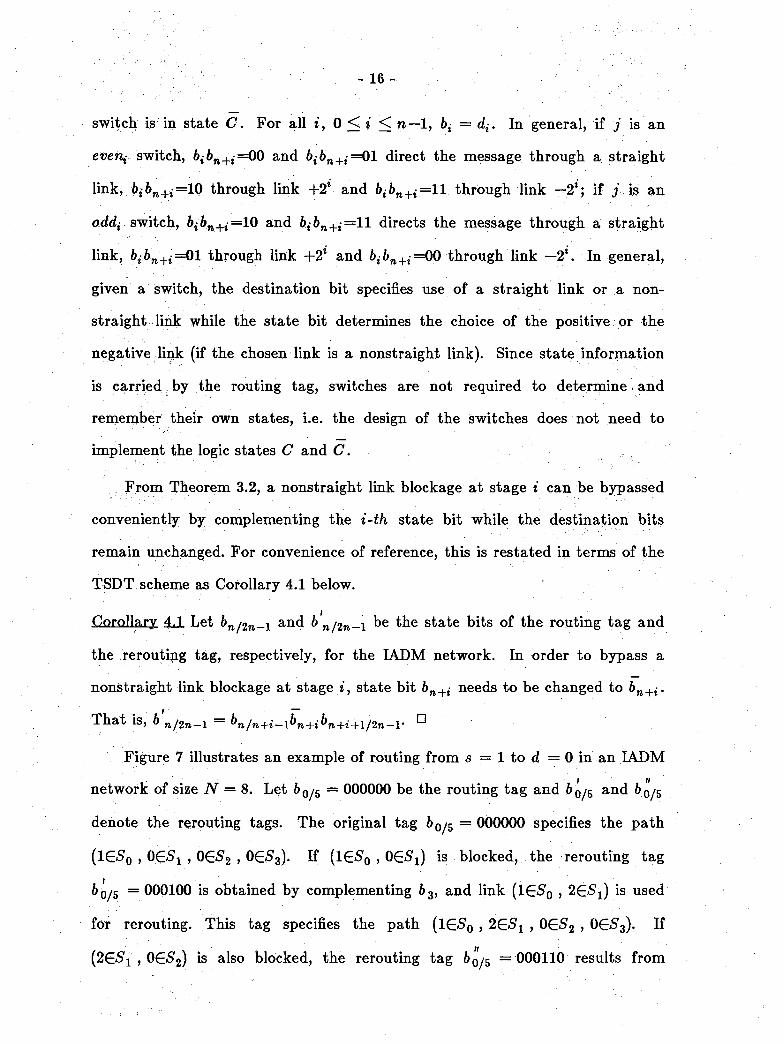
switch is in state C. For all i, 0 < * < n—1, 6, = d,-. In general, if j is an
even,- switch, 6,6n+,=00 and 6,-6n+,=01 direct the message through a straight
link, 6,-6n+,-=10 through link +2* and 6,-6n+,-=ll through link —2*; if j is an
odd,- switch, 6,-6n+,-=10 and 6,6n+,-=ll directs the message through a straight
link, bibn+i =01 through link +2l and =00 through link —2*. In general,
given a switch, the destination bit specifies use of a straight link or a non-
straight link while the state bit determines the choice of the positive or the
negative link (if the chosen link is a nonstraight link). Since state information
is carried by the routing tag, switches are not required to determine and
remember their own states, i.e. the design of the switches does not need to
implement the logic states C and C.
From Theorem 3.2, a nonstraight link blockage at stage i can be bypassed
conveniently by complementing the i-th state bit while the destination bits
remain unchanged. For convenience of reference, this is restated in terms of the
TSDT scheme as Corollary 4.1 below.
Corollary 4JL Let &n/2n-i an^ & n/2n-i state bits of the routing tag and
the rerouting tag, respectively, for the IADM network. In order to bypass a
nonstraight link blockage at stage i, state bit bn+i needs to be changed to bn+i.
That is, b n/2n-i = bn/n+i_1bn+ibn+i+1/2n-l' n
Figure 7 illustrates an example of routing from s = 1 to d = 0 in an IADM
network of size N = 8. Let b 0/5 = 000000 be the routing tag and and 6 0/5
denote the rerouting tags. The original tag i>0y5 = 000000 specifies the path
(1G<50 , OE-S'i , 0ES^ , OES^). If (lEi^o , OES^) is blocked, the rerouting tag
60/5 = 000100 is obtained by complementing b3, and link (lESp , 2G5i) is used
for rerouting. This tag specifies the path (IE-S'q , 2E<S,1 , 0E<52 , 0(ES3). If
(2E<S'1 , OE-S^) is also blocked, the rerouting tag 6q/5 = 000110 results from

- 17 -
complementing b 4, and link (26-5! , 4G*S,2) is used for rerouting. This tag
specifies the path (IESq , 2ESX ,4€52,O&S3).
As discussed in Section 3, a straight link blockage and a double nonstraight
link blockage cannot be overcome easily; implementing a backtracking (or look
ahead) mechanism is a must in order to evade these types of blockages. Since
all links in the routing path from stage i—k+1 to stage i consist of only
straight links, backtracking of at least k stages is required to find the switch
fropi which; an alternate routing path branches. That is, at least k state bits
need to be considered for change. Due to the similarity between Theorems 3.3
and 3.4, the TSDT schemes for finding the rerouting paths from Theorems 3.3
and 3.4 are exactly the same, which is stated as Corollary 4.2.
Corollary 4J& Let bnj2n_i and b n/2n-i be the state bits of the routing tag and
the rerouting tag, respectively, for a source/destination pair in the IADM net
work. Let'*—A; be the largest stage number for i > k > 0 such that a switch at
stage i—k is connected to a nonstraight link on the routing path. In order to
bypass a straight link blockage or a double nonstraight link blockage at stage i,
only state bits &»+(*-*)/»+* <-i need to be changed; (i)
b'h/„+(,•_!) = ^ the nonstraight link at stage i—k of the ori
ginal path is link -2i~k, and (ii) 6= 6rt/re+(t_fc)_1dt_A/i_1 if the non
straight link at stage i—k of the original path is link +2l~*. The state bits
6 n+t/2n_i have arbitrary values in both cases.
Proof: See Appendix Al. □
The example in Figure 7 can be used to illustrate the TSDT scheme for (a)
a straight link blockage and (b) a double nonstraight link blockage, (a) Again
the tag i>0^g = 000000 specifies a path (1G50,00?! , OGS2 , OG^). If the
straight link (0£Sl , 0G92) is blocked, the rerouting tag can be 000110 which

- 18 -
specifies path (l£S0 , 2£S1 , 4GS2,0ES3) by having
63+063+163+2 = d0dib3+2 — HO. Since state bits 63+163+2 can be arbitrary,
000100, for example, is also a valid rerouting tag; it specifies path
(lGiS'o , 2&S'i , OE^ > 0G<S,3). (b) Let the tag 6 0/5 = 000110 specifies a path
(l€#o , 2&fi > 4E<S2 > If both nonstraight output links of 4E52 are
blocked, the rerouting tag b'0/5 can be 000100 which specifies path
(lG^o r 2€<S'i , OE-S^ , OE^) by having b'3+0b's+lb'3+2 = 63+0d1d2- Since state
bits 6 3+2 can be arbitrary, 000101 is also a valid rerouting tag which also
specifies the same path.
The rerouting path computed from Corollary 4.2 is blockage-free from
stage 0 to stage i. While the rerouting path is different from the original rout
ing path from stage i—k to stage i, the routing path from stage 0 to i — k— 1
remains the same. This results from the fact that backtracking always
proceeds backward along the original path until it stops at stage i—k, and the
rerouting path only changes course from stage i—k onwards. Although state
bits bn-\-i/2n—i remain unchanged, the routing path from stage i to n — 1 may
still be altered due to the changes from stage i—k to i. For example, in Figure
5, the switch on the original routing path at stage t+l'is yE^+i whereas the
switch on the rerouting path at stage *+1 may be (j -t-2* +1)E-S'i*+1, which may
further induce changes at higher-order stages.
In the TSDT scheme, the tag can be computed by the message sender
which is assumed to know the location of faulty links and switches in the net
work. Thus, rerouting is transparent to the switches in the sense that the tag
computed by the sender of the message simply avoids the usage of faulty links
and switches. Therefore switches do not require any extra hardware for rerout
ing purposes. An alternative is to implement dynamic rerouting for the TSDT
- 19 -
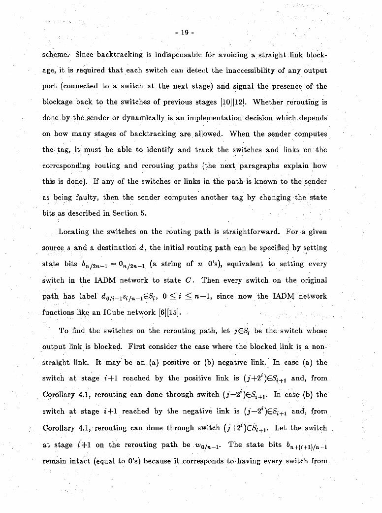
scheme. Since backtracking is indispensable for avoiding a straight link block
age, it is required that each switch can detect the inaccessibility of any output
port (connected to a switch at the next stage) and signal the presence of the
blockage back to the switches of previous stages [10] [12]. Whether rerouting is
done by the sender or dynamically is an implementation decision which depends
on how many stages of backtracking are allowed. When the sender computes
the tag, it must be able to identify and track the switches and links on the
corresponding routing and rerouting paths (the next paragraphs explain how
this is done). If any of the switches or links in the path is known to the sender
as being faulty, then the sender computes another tag by changing the state
bits as described in Section 5.
Locating the switches on the routing path is straightforward. For a given
source s and a destination d, the initial routing path can be specified by settiiig
state bits i>n/2n-i = 0n/2n-i (a string of n 0’s), equivalent to setting every
switch in the IADM network to state C. Then every switch on the original
path has label 0<* < n— 1, since now the IADM network
functions like an ICube network [6] [15].
To find the switches on the rerouting path, let jGS; be the switch whose
output link is blocked. First consider the case where the blocked link is a non-
straight link. It may be an (a) positive or (b) negative link. In case (a) the
switch at stage *+l reached by the positive link is (j+21)(ESi+1 and, from
Corollary 4.1, rerouting can done through switch (j—2t)ESi+1. In case (b) the
switch at stage t'+l reached by the negative link is (j—2*)G<S'j+1 and, from
Corollary 4.1, rerouting can done through switch (j+2t)£Si+1. Let the switch
at stage t+1 on the rerouting path be w>o/»-i* The state bits 6w+(t+1yn_1
remain intact (equal to 0’s) because it corresponds to having every switch from

- 20 -
stage i-f-1 to n—1 remain in state C so that the IADM network from stage i+1
to n—1 can emulate the ICube network from stage i +1 to n—1. Thus, the bits
/, t+1 <• n— 1, of the label of a switch on the rerouting path are
From Lemma 2.1, bits 0 to /—1, 1 < / < t-f-1, of the label of a switch on a path
to destination do/w-i must be d0//-i* Hence the switch on the rerouting path
from stage *+l to n— 1 has label t-|-l < l < n— 1.
Next Consider the case where the blockage of ./GS1,- is a straight link block
age or a: double nonstraight link blockage so that backtracking is necessary.
There are two sub-cases for each type of blockage: (i) the nonstraight link
found in backtracking is a negative link and fii) it is a positive link. Here only
sub-case (i) of the straight link blockage is considered; the other cases can be
dealt with similarly. From the proof of Corollary 4.2 (case (i) only), the switch
on the rerouting path is (j+2l)ESi, i—k < l < i. The switch of stage *+1 on
the rerouting path is j£Si+1 if K+i = 0 and j&Si+1 is an odd,- switch or if
bn+i — 1 and j£Si+1 is an even,- switch, and is (j-f22+1)C*S',-+1 if b^+i = 0 and
j&Si+1 is a,n even,- switch or if b'n+i =1 and j£Si+1 is an odd,- switch. The
identification of switches on the rerouting path from stage i +1 to n —1 is done
as in the case of a nonstraight link blockage described above.
The blocked link can be represented by the two switches joined by the link.
Since every switch on the original routing path and the rerouting paths can be
easily identified as described above, it can be readily determined whether or not
the blpclsed link is on the current path.
In summary, for both SDT schemes, the binary representation of the desti
nation address can be used directly as the routing tag. In the SSDT scheme,
rerouting tags are not needed and in the TSDT scheme, rerouting tags result
from simple bit complementing operations. In terms of complexity of the

- 21 - '
computation for a rerouting tag, the SSDT scheme and the TSDT scheme for
one instance of nonstraight link blockage require timeXspace complexity 0(1);
an improvement over previous proposed schemes [9] dealing with rerouting for a
nonstraight link blockage that require timeXspace complexity O(logiV). In [10]
a single-stage look-ahead scheme for rerouting of a straight link blockage was
proposed; it requires use of two’s complement to compute the positive and nega
tive dominant tags so that the scheme has timeXspace complexity of O(logiV).
Note that the single-stage look-ahead rerouting scheme is valid only for some
cases of the straight link blockage; it cannot be applied to any case of the
straight link blockage. From Corollary 4.2, fc-stage backtracking is needed for
a straight link blockage and k bits of the state bits needs to be changed; thus
the complexity of the TSDT scheme for a nonstraight link is 0(h). If only
single-stage backtracking (corresponds to single-stage look-ahead) is necessary,
rerouting can be done dynamically and the complexity is 0(1), an improvement
over the scheme in [ 10].
5. A Universal Rerouting Algorithm for Multiple Blockages
The TSDT scheme can be applied to not only one instance of some block
age, but also can be applied repetitively each time a new blockage is encoun
tered as the message propagates along. This section considers the derivation of
an algorithm to deal with any case of multiple blockages. The backtracking
schemes proposed in Corollary 4.2 find a rerouting path for a straight link
blockage and a double nonstraight link blockage. Nevertheless, it is possible
that blockages also exist on the rerouting path; then further backtracking to a
lower-order stage is needed. Since this phenomenon can recur, repeated back
tracking may be necessary due to blockages on the rerouting paths. The

- 22 -
algorithm BACKTRACK described next performs iterated backtracking to find
an alternate routing path. It underlies a universal rerouting algorithm (called
REROUTE) to be shown later that can find a routing path, if there exists any,
to bypass multiple blockages in the network.
The inputs to algorithm BACKTRACK are the current routing path P, the
stage number i where a blockage occurs, and state bits b'n/2n_i representing
path P. The algorithm returns updated values of the state bits b'n/2n_i which
specify a rerouting path that is blockage-free from stage 0 to stage i if such a
rerouting path exists, or returns FAIL if the blockages on the current routing
path and the rerouting paths eliminate the possibility of communication
between the source and the destination. It is assumed that the blockage on the
original routing path at stage i is a straight link blockage or a double non
straight link blockage and is the switch whose output links are the
blocked links. Informal explanations for the algorithm will be given following
the algorithm and the correctness proof of this algorithm can be found in
Appendix A2.
Algorithm BACKTRACK (and REROUTE) presumes existence of the
knowledge of all blockages in the network. The network controller is responsi
ble for collecting this information and maintaining a global map of blockages,
which is accessible to every sender of the messages in order to compute a path
to avoid the blockages. In addition, since it may take several iterations before a
blockage-free path can be found or it can be concluded that no blockage-free
paths exist, the sender of the message needs to maintain and update the loca
tions of switches on the rerouting path in each iteration.
Algorithm BACKTRACK {P,i, b'n/2n J
0: q — stage number where a blockage occur.
• q «—
1: P= the current routing path.
Backtrack on path P from stage q to find a nonstraight link. If no non-
straight link exists at any preceding stage, return(FAIL); otherwise assign
to r" the stage number where the first nonstraight output link is found.
2: If the nonstraight link at stage r on the routing path is +2r, assign flag
link found value 0; if it is — 2r, assign linkfound value 1.
3: If linkfound = 0, b'n/2n-i «— b'n/n+r-idr/q-ib'n+q/2n-v if linkfound = 1,
b ;n/2n-l b n/n+r-ldr/q-lb n+q/2n-V
4a: This step applies only when the blockage at stage q on path P is a straight
link blockage.
If linkfound — 0, set b'n+q = dq; if ({j—2q)£Sq , (j—23+1)G<S'9+1) is blocked,
change b'n+q to dq; furthermore, if ((j—2q)(zSq , j(zSq+l) is also blocked,
return(FAIL). K linkfound = 1, set b'n+q = dq; if
((j+2q )£.Sq v(i+29+1)&S,g+1) is blocked, change b'n+q to dq; furthermore, if
{( j+2q)£.Sq , j£Sq+1) is also blocked, return(FAIL).
4b: This step applies only when the blockage at stage q on path P is a double
nonstraight link blockage.
If {{j—2q)€.Sq , (j—2q)^Sq+1) is blocked for linkfound — 0, or
([j+2q)ESq , (j+2q)ESq+1) is blocked for linkfound — 1, return(FAIL).
5: Let Q denotes the part of the rerouting path (specified by the tag in step
3) from stage r +1 to q from step 3.
If linkfound =0, Q —
{{j-2r+1)esr+1, • • • , , {j-2q)esqy, if linkfound = i,
- 23 -

- 24 -
Q = ((y+2r+1)esr+1, • • • , (y+25-1)G59_1, (y+2*)es9).
If a blockage occurs on path Q, return(FAIL).
6: If link found = 0 and ((j—2r)(E.Sr , (j—2r+1)(ESr+1) is blocked, or if link-
found = 1 and ((j+2r)E.Sr , (i+2r+1)G5'r+1) is blocked, go to step 7; else
return(6w/2n_1).
7: j +- j+2r, q « r.
8: Backtrack on path P from stage q to find a nonstraight link. If no non
straight link exists at any preceding stage, return(FAIL); otherwise assign
to r the stage number where the first nonstraight output link is found.
9: If link found =0 and the nonstraight link at stage r is — 2T, or if link-
found = 1 and the nonstraight link at stage r is +2f, return(FAIL).
10: If Unkfound =0, b'niin_x «— b'ninJrr_ldTiq_lb'nJrqj2n_x', if linkfound = 1,
^ n/2n—l b n/n+r-ldr/q-lb n+q/2n-V Go to step 4b.
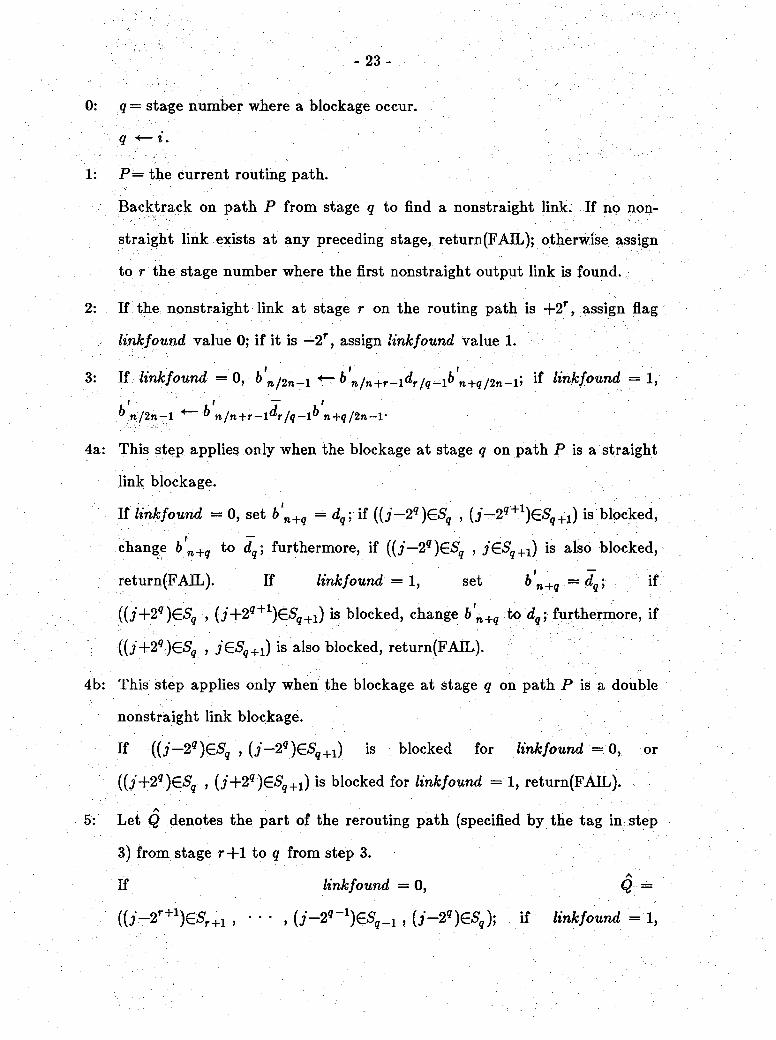
Step 0 is the initialization step. From Theorems 3.3 and 3.4, an alternate
path exists for avoiding a straight link blockage or a double nonstraight link
blockage if and only if there exists a nonstraight link at some stage preceding
stage r; step 1 of the algorithm searches backward for such a nonstraight link.
If not found, it results in premature termination of the algorithm, reflecting the
fact that no alternate paths for rerouting exist. Step 2 is used to differentiate
the cases when the nonstraight link at stage r found in the first backtracking is
a positive link and when it is a negative link; flag linkfound is assigned 0 for
the former and 1 for the latter. If a nonstraight link exists at some stage
preceding the blockages, in step 3, Corollary 4.2 is applied to find the stage bits
specifying the rerouting path; cases (i) and (ii) in Corollary 4.2 correspond to
linkfound = 1 and linkfound = 0, respectively, and q and r correspond to i
- 25 -
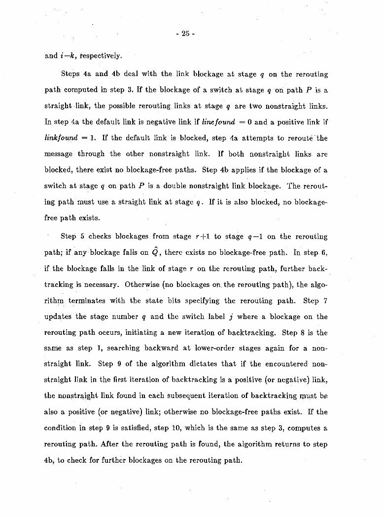
and i—k, respectively.
Steps 4a and 4b deal with the link blockage at stage q on the rerouting
path computed in step 3. If the blockage of a switch at stage q on path P is a
straight link, the possible rerouting links at stage q are two nonstraight links.
In step 4a the default link is negative link if line found = 0 and a positive link if
link found = 1. If the default link is blocked, step 4a attempts to reroute the
message through the other nonstraight link. If both nonstraight links are
blocked, there exist no blockage-free paths. Step 4b applies if the blockage of a
switch at stage q on path P is a double nonstraight link blockage. The rerout
ing path must use a straight link at stage q. If it is also blocked, no blockage-
free path exists.
Step 5 checks blockages from stage r+1 to stage q— 1 on the reroutingA,
path; if any blockage falls on Q, there exists no blockage-free path. In step 6,
if the blockage falls in the link of stage r on the rerouting path, further back
tracking is necessary. Otherwise (no blockages on the rerouting path), the algo
rithm terminates with the state bits specifying the rerouting path. Step 7
updates the stage number q and the switch label j where a blockage on the
rerouting path occurs, initiating a new iteration of backtracking. Step 8 is the
same as step 1, searching backward at lower-order stages again for a non
straight link. Step 9 of the algorithm dictates that if the encountered non
straight link in the first iteration of backtracking is a positive (or negative) link,
the nonstraight link found in each subsequent iteration of backtracking must be
also a positive (or negative) link; otherwise no blockage-free paths exist. If the
condition in step 9 is satisfied, step 10, which is the same as step 3, computes a
rerouting path. After the rerouting path is found, the algorithm returns to step
4b, to check for further blockages on the rerouting path.

- 26 -
For each source/destination pair, a link on some routing path for the
source/destination pair is called a participating link. As a direct result of
Theorem 3.2, the set of participating output links of a switch is composed of
either its straight output link or both of its nonstraight output links, but never
all of them. So the output link blockages of a switch, for a given
source/destination pair, can only be a straight link blockage, a nonstraight link
blockage, or a double nonstraight link blockage. Algorithm BACKTRACK
deals with the first and third kind of blockages, and the second kind of block
age can be overcome by applying Corollary 4.1. Algorithm BACKTRACK and
Corollary 4.1 can be used to form a universal algorithm capable of rerouting
messages when multiple blockages exist in the IADM network. This algorithm,
called REROUTE, returns state bits b n/2n-i specifying a blockage-free rerout
ing path if one exists, or returns FAIL otherwise.
Algorithm REROUTE (P, b'n/2rt_i)
0: P= the original routing path.
bn/2n-i~ the routing tag specifying the original routing path.
6 n/2w_i= the rerouting tag specifying the rerouting path.
& n/2n-l ■*“" ^»/2w-l*
1: Let i be the smallest stage number such that there exists a blockage at
stage i on path P. If no blockages occur on path P, return(i/w/<2n-i)*
2: If the blockage at stage i on path P is a nonstraight link blockage and the
other nonstraight link is not blocked, apply Corollary 4.1 to find state bits
b n/2n-l and g° to step 4.
3: & n/2n—i * BACKTRACK^, 6 n/2fl_i).

- 27 -
4: Q = the rerouting path specified by state bits b'n/2n_1.
P «— Q and go to step 1.
Step 0 is the initialization step. At the end of each iteration, a blockage-
free path from stage 0 to stage i is found. Then a new iteration starts and i is
given a new value in order to find a path avoiding the blockages at a higher-
order stage. The only terminating conditions for algorithm REROUTE are that
a return of FAIL from step 3 indicating that no blockage-free paths exist and
the return from step 1 indicating a blockage-free path is found. Algorithm
REROUTE is executed iteratively to evade blockages from lower-order to
higher-order stages. The correctness of this algorithm follows from the correct
ness of algorithm BACKTRACK and Corollary 4.1.
6. Permutation Routing and Cube Subgraphs of the IADM Network
The results discussed so far are a consequence of the existence of spare
nonstraight links in addition to the ICube network embedded in the IADM net
work. This section pursues this issue further by showing that there exist multi
ple distinct subgraphs in the IADM network, each called a cube subgraph, that
are isomorphic to the ICube network. Two cube subgraphs are considered to be
distinct if they differ in at least one link. As mentioned in the introduction of
this paper, the cube-type networks have been studied extensively in the litera
ture and shown to be topologically equivalent. Together with results from these
Studies, tbe knowledge of how to identify cube subgraphs can help the under
standing of the capabilities of the IADM network and be useful for permutation
routing in the IADM network.AT
Since each switch can be in state C or C, there are as many as 2
(= NN) network states, although each does not necessarily generate a unique
- 28 -
permutation. Setting a switch to a certain state indicates that one of its non-
straight output links can be used for routing (i.e. it is active) while the other
cannot. Thus, each network state can be associated with a subgraph of the
IADM network which contains only the active links. When all switches in the
IADM network are set to state C, the IADM network functions as an ICube
network; this network state corresponds a cube subgraph. The constructive
derivation of a lower bound for the number of cube subgraphs of the IADM net
work uses the two basic ideas discussed in the next paragraphs.
Since +2n_1 = — 2n~l mod N, = Cn-\(j,tn-i), i.e. the state of
each switch of stage n—1 is irrelevant in the sense that any switch at stage
n— 1 is always connected to the same two switches at stage n. Consequently,
given any cube subgraph, there exist (2^—1) subgraphs isomorphic to it which
differ only in their choices of the nonstraight link +2n_1 or —2n_1 at stage n— 1.
Therefore, the total number of distinct cube subgraphs is given by the product
of,2* and the number of distinct subgraphs of the IADM network from stage 0
to stage n— 2 that are isomorphic to the same stages in the ICube network.
The calculation of the number of subgraphs in the first n—1 stages uses an
idea similar to that proposed in [5] for reconfiguring the DR network so that it
performs as a Generalized Cube network. All switches of the IADM network
are logically relabeled by adding a constant x, 0 < x < N—1 to the original
labels, i.e. switch j becomes j = j + x. By setting each switch to be an even*
or oddj switch according to its new label and having all switches be in state C,
a cube subgraph results for each relabeling. However, of the N possible sub-
Ngraphs, only — are distinct as far as the first n—1 stages are concerned. This 2
result is stated in Theorem 6.1. A graphical interpretation of cube subgraph
isomorphism for an IADM network of size N=8 is illustrated in Figure 8. In
- 29 -
Figure 8, each physical switch j acts as a logical switch / = (j+1) mod 8. The
isomorphism to the ICube network can be easily visualized by moving switch 7
to the top of each stage as shown in the figure. Notice that setting some switch
to state C according to its logical label may be equivalent to setting the switch
to state C according its original label. For instance, switch 0650 (logical label
1) is set to state C in Figure 8.
N NTheorem 6.1 There exist at least —-2iV distinct cube subgraphs in the IADM
network.
Proof: See Appendix Al. □
In order to reconfigure the IADM network to one of its cube subgraphs,
each switch of stage i, for 0 < i < n— 2, needs to know the i-th bit of its logi
cal label. This can be done by sending the same logical label to every switch in
the same row at system reconfiguration time. Each switch is set as being an
odd{ or even,- switch by examining the i-th bit of the logical label. All switches
operate in state C according to its logical label with the exception of those at
stage n—1 for which different states correspond to different subgraphs.
The results of this section can be used in different ways. One usage is in
characterizing a class of permutations performable by the IADM network. Per
mutations passable by the ICube network are discussed in [15] and adaptable
from [6]. Thus, the IADM network can perform all of these permutations plus
the same set of permutations with a given x added to both the same source and
Ndestination labels, 0 < z <—.— 2 Another use of the results of this section is
that the IADM network can pass the permutations performable by the ICube
network when the ICube network embedded in the IADM network experiences
nonstraight link failures. This is done by incorporating a reconfiguration

- 30 -
function in the system that reassigns each switch j to (j+x) and reconfiguring
the IADM network to a corresponding cube subgraph which does not include the
faulty ndnstraight links. In [21] it is shown that any of the cube-type networks
can pass the permutations performable by the others by incorporating appropri
ate reconfiguration functions. By the same token, the IADM network with a
nonstraight link fault can also pass the permutations performable by the cube-
type networks by including these reconfiguration functions in the system.
7. Concluding Remarks
One of the main contributions of this paper is the identification of destina
tion tag routing schemes for the IADM network. They are simpler and more
efficient than previously known approaches, thus requiring less complex switches
and reducing message communication delays due to routing overhead. In the
SSDT scheme rerouting can be done when nonstraight links fail and in the
TSDT scheme both the straight and double nonstraight link blockages can be
avoided. As for the SSDT scheme, routing and rerouting are transparent to the
source and only negligible hardware and time are used by each switch for rout
ing and rerouting purpose. These are considerable advantages over previously
proposed schemes which do not use destination tags and require extra hardware
or delays of O(logiV) complexity instead of 0(1). In addition, previous works all
deal only with certain types of blockages. Based on the TSDT scheme, a
universal rerouting algorithm is derived, which is capable of avoiding any com
bination of multiple blockages if there exist a blockage-free path and indicating
absence of such a path if there exists none. The rerouting capabilities of the
new schemes can be readily used for fault-tolerance and load balancing pur
poses since they adequately exploit the redundancy available in the LADM

- 31 -
network.
Another contribution of this paper is the constructive derivation of a lower
bound on the number of cube subgraphs of the IADM network. While it was
previously known that the ICube network is a subgraph of the IADM network,
N Nthis paper shows that there exist at least —•2iV distinct cube subgraphs. This,
combined with previous multistage cube network studies, can help characterize
some of the permutations performable by the IADM network. As other use of
the subgraph analysis, it is shown how to reconfigure the IADM network under
nonstraight link faults to pass the cube-admissible permutations.
Perhaps the most fundamental contribution of this paper is that of the net
work state model used for the IADM and the ICube networks. The essence of
this model is in the recognition that the routing action of each switch is concep
tually dependent on its position in the network (topological information), its
state (functional information), and the destination of the message (routing
information). Topological information is fixed and, when using destination
tags, the same can be said of routing information for a given message destina
tion. Consequently, the routing path is solely determined by the state of the
network. These basic concepts are applicable to networks other than those con
sidered in this paper; the state model can help devise new designs, solve routing
problems, and understand relationships among networks.
References
[l] D. Agrawal, "Graph Theoretical Analysis and Design of Multistage Inter
connection Networks," IEEE Trans. Computers, Vol. C-32, No. 7, July 1983,
pp. 637-648.

- 32 -
[2] K. E. .Batcher, "The Flip Network in STARAN," 1976 Int’l Conf. Parallel
Processing, Aug. 1976, pp. 65-71.
[3] T-Y Feng, "Data Manipulating Functions in Parallel Processors and their
Implementations," IEEE Trans. Computers, Vol. C-23, No. 3, Mar. 1974,
pp. 309-318.
[4] L. R. Goke and G. J. Lipovski, "Banyan Networks for Partitioning Mul
tiprocessor Systems," 1st Ann. Symp. Computer Architecture, Dec. 1973,
pp. 21-28.
[5] M. Jeng and H. J. Siegel, "A Fault-tolerant Multistage Interconnection Net
work for Multiprocessor Systems Using Dynamic Redundancy," 6tk Int’l
Conf. Distributed Computing Systems, May 1986, pp. 70-77.
[6] D. H. Lawrie, "Access and Alignment of Data in an Array Processor " IEEE
Trans. Computers, Yol. C-24, No. 12, Dec. 1975, pp. 1145-1155.
[7] D. Lee and K. Y. Lee, "Control Algorithms for the Augmented Data Mani
pulator Network," 1986 Int’l Conf. Parallel Processing, Aug. 1986, pp. 123-
130.
[8] M. Malek and W. W. Myre, "A Description Method of Interconnection Net
works," IEEE Tech. Committee Distrib. Process., Quart. Vol. 1, Feb. 1981,
pp. 1-6.
[9] R. J. McMillen and H. J. Siegel, "Routing Schemes for the Augmented Data
Manipulator Network in an MIMD System," IEEE Trans. Computers, Yol.
C-31, No. 12, Dec. 1982, pp. 1202-1214.
[10] R. J. McMillen and H. J. Siegel, "Performance and Fault Tolerance
Improvements in the Inverse Augmented Data Manipulator Network," 9th
Ann. Symp. Computer Architecture, Apr. 1982, pp. 63-72.

[11] R. J. McMillen and H. J. Siegel, "Evaluation of Cube and Data Manipula
tor Networks," J. Parallel and Distributed Computing, Vol. 2, No. 1, Feb.
1985, pp. 79-107.
[12] K. Padmanabhan and D. H. Lawrie, "A Class of Redundant Path
Multistage Interconnection Networks," IEEE Trans. Computers, Vol. C-32,
No. 12, Dec. 1983, pp. 1099-1108.
[13] D. S. Parker and C. S. Raghavendra, "The Gamma Network: A Multipro
cessor Interconnection Network with Redundant Paths," 9th Ann. Symp.
Computer Architecture, Apr. 1982, pp. 73-80.
[14] D. S. Parker and C. S. Raghavendra, "The Gamma Network," IEEE Trans.
Computers, Vol. C-33, No. 4, Apr. 1984, pp. 367-373.
[15] M. C. Pease, III, "The Indirect Binary n-Cube Microprocessor Array,"
IEEE Trans. Computers, Vol. C-26, No. 5, May 1977, pp. 458-473.
[16] H. J. Siegel, Interconnection Networks for Large-Scale Parallel Processing:
Theory and Case Studies, Lexington Books, D. C. Heath and Company,
Lexington, MA, 1985.
[17] H. J. Siegel and S. D. Smith, "Study of Multistage SIMD Interconnection
Networks," 5th Ann. Symp. Computer Architecture, Apr. 1978, pp. 223-229.
[18] H. J. Siegel and R. J. McMillen, "The Multistage Cube : A Versatile Inter
connection Network," IEEE Computer, Vol. 14, Dec. 1981, pp. 65-76.
[19] A. Varma and C. S. Raghavendra, "On Permutations Passable by the
Gamma Network," J. Parallel and Distributed Computing, Vol. 3, No. 1, pp.
72-91, Mar. 1986.
[20] C-L. Wu and T-Y. Feng, "On a Class of Multistage Interconnection Net
works," IEEE Trans. Computers, Vol. C-29, No. 8, Aug. 1980, pp. 694-702.
- 33 -

- 34 -
[21] C-L. Wu and T-Y. Feng, "The Reverse-Exchange Interconnection Net
work," IEEE Trans. Computers, Vol. C-29, No. 9, Sept. 1980, pp. 801-811.

- 35 -
Appendix A1
Proof of Theorem 8,8
The "only if" part follows immediately from Theorem 3.2. To prove the "if"
part, let j£Sj be the switch whose straight output link is the blocked link on
the routing path and i—k be the largest stage number for i > k > 0 such that
a switch at stage i—k has a nonstraight output link on the routing path, (i)
Assume that the nonstraight link at stage i—k found in backtracking is link
—2 . Clearly, as illustrated in Figure 5, the path
, (j+2'~kJtl)eSi_k+1 , .... , (j+2t)esi , jesi+1) is a rerouting
path for path {{j+2* k)GSi_k , , jESi_k+2 , .... , , j£Si+l). (ii)
Assume that the nonstraight link at stage i — k found in backtracking is link
4-2*"*; similarly path
, {j~2l~k+1)eSi_k+l , .... , {j-2l)£St , jesi+1) is a rerouting
path for path ((i-2,_*)€5i_jfc , , jESi_k_i.2 , .... , iCS; , jESi+1). □
Proof of Theorem 8.4
The "only if" part again follows immediately from Theorem 3.2. To prove the
"if" part, let notations i, i—k and jESi be the same as those in the proof of
Theorem 3.3. The proof is illustrated in Figure 6. From Theorem 3.2,
(j—2l)£Si+1 and (y4-2*)G*S't+1 can reach the same subset of destinations so that
it does not matter which is on the rerouting path, (i) Assume that the non-
straight link at stage i—k found in backtracking is link —2l~k, It is self-
explanatory that path
i[j-^~k)eSi_k , (y+2i-fc+1)6^_fc+1 , .... , U+2i)eSi , {j+2i)esi+1) is a rerout
ing path for both paths {{j+2t~k)eSi_k , j€Si_k+1 , • • • , jGS{ , {j+2l)ESi+l)
and ((i+2‘, jES{_k+1 , ■ • • , jES{ , (i-2*)GSl+1). (ii) Assume that
the nonstraight link at stage i—k found in backtracking is link +2*~k; similarly
path (U-2i-t)€Si^ , ,...., tf-ifjesj) , (j-2*)6Si+1) is a
rerouting path. Note that the participating input link of j&S',- may be a non
straight link; however, this is just a special case for k — 1. □
Proof of Corollary \.2
First two lemmas are presented, which are to be used to prove Corollary 4.2.
Lemma Al.l In the TSDT scheme, the links +2l and —2l connected to a switch
jdzSi are specified by tag bits = j)and 6/6w+/ = j)ji respectively, and
the straight link is specified by btbn+l = j^) or btbn+l = j)]).
Proof: Follow immediately from the definition for the TSDT scheme. □
Lemma Al.2 (i) Let jG<Sj and (j-l-2/)G<S,;+1 be two switches joined by a positive
nonstraight link +2l and they are on a path to the destination d0^n_v In the
TSDT scheme, the routing tag can be set to b[bn+i — dtdi to control routing to
send the message from jG-S) to {j+2l)£Sl+1. (ii) Let j£Sl and [j— 2l)ESl+1 be
two switches joined by a negative nonstraight link — 2l and they are, on a path
to the destination d0/n_1. In the TSDT scheme, the routing tag can be set to
bibn+i = d[di to control routing to send the message from jG<S/ to (j—2^)G*S’/.1_1-
Proof: Only proof for (i) is given and proof for (ii) is similar. From Lemma 2.1
and the proof for Theorem 3.1, the switch j{= j+2i)GS'j+r has the label
io/n-i = do/l-idiwi+i/n-i) where wl+ljn_x depends on network state. So
j i = dt. Additionally, j / = because j' = j +2l. Hence j) = d[. By Lemma
Al.l, b[bnj^i = d[d[. D
Proof of Corollary 4.2:
Only proofs of (i) for (a) a straight link blockage and for (b) a double non-
straight link blockage are given; proofs of (ii) for cases (a) and (b) are similar.
Since the destination bits always remain unchanged, only state bits need to be
- 36 -
- 37 -
considered, (a) This proof first derives the state bits controlling the rerouting
path Q+ = ((i+2*:-fc)G5f_fc , (i+2*-*+1)6S;._*+1 , .... , (i+2*‘)G5f) in Figure 5
(which illustrates the proof of Theorem 3.3). Since the links on path Q+ are all
positive nonstraight links, by Lemma A1.2, 6= d,-represents
the state bits for path Q+. In addition, by Theorem 3.2, the link of stage i on
the rerouting path can be either link —2* ((i+2* )££,- , jESi+1) or link +2*
((j+2i)G5i , (j+2i+1)esi+1). Thus b'n+i can be 0 or 1. (b) Notice that the
rerouting paths from stage i—k to stage i found in Theorem 3.3 and Theorem
3.4 are the same except the the link of stage i on the rerouting path is a non
straight link in Theorem 3.3 (Figure 5) and it is a straight link in Theorem 3.4
(Figure 6). By Lemma Al.l, the state bit b'n+i, which specifies the straight link
at stage i in Theorem 3.4, can be 0 or 1. So the state bits specifying the
rerouting path from stage i—k to stage i are the same as those in (a).
b w+(t+i)/2w-i can be arbitrary because, regardless of the values of b n+(,-t-i)/2n-i>
as long as the destination bits are &o/n-i ~ ^o/n-v the path can reach the des
tination d0/n—l* a
Proof of Theorem 6.1
Consider two cube subgraphs generated by adding x and y, respectively, to the
original labels of all switches of the IADM network. It is shown that
N Nx mod — ^ y mod — is a sufficient condition for these subgraphs to be dis- 2 2
tinct in the sense that they differ in at least one link of the first n—2 stages (it
is also possible to show the necessity of this condition). To prove that the sub
graphs are distinct, it is shown that, given the condition above, there exists
some physical switch j* £Sn_2 such that (j*+x) and (j*+y) differ in their
(n—2)-th bit, i.e. the switch with logical label (j +x) is an even,- switch and the$switch with logical label (j +y) is an odd,- switch, or vice versa. This implies

- 38 -
that a different nonstraight link is used and therefore the subgraphs are dis
tinct. Let the h-th bit of ^o/n-2 and y0/n_2 be the highest order bit such that
xh^yhr i-ev xh+i/ri-2 = Vh+i/n-2- Here h < n— 2 since only the topology of the
IADM network from stage 0 to stage n— 2 is considered. Without loss of jgen-
erality, assume that xh = 0 and yh =1 and let j a/n-2 = %/h-ilxh+i/n-2
(where 00/^_1 is a string of h 0’s). Then
tjc(j +x)o/w_2 = ®0/a-1(0+1)1/1+1/w_2 = xo/h-i^-h/n-3^ and
{j +J/)o/n-2 = J/0//i-l(1+1)1/i+l/ji-2 = yo/h-l^h/n-3^
Ndiffer in the value of their (n—2)-th bit. Therefore there exist — distinct cube
subgraphs when considering only the topology of the IADM network from stage
N0 to stage n— 2. For each of these cube subgraphs, there exist 2N subgraphs
of the IADM network which differ from it only in the choice of the nonstraight
links at stage n—1. Thus, the IADM network contains at least —•2JV distinct
cube subgraphs. □
Appendix A2: Proof of Algorithm BACKTRACK
Terminology and two lemmas are introduced first in order to lay the
ground for the verification of algorithm BACKTRACK. Given a source and a
destination, a switch on some routing path for the source/destination pair is
called a pivot. Conversely, by the definition of a pivot, a path in the IADM net
work can reach the destination if and only if it passes through a pivot at each
stage. The set of pivots at each stage varies with different source/destination
pair and is characterized by the following lemma.

- 39 -
Lemma A2,1 Let k be the smallest stage number for which there exists a non
straight link on at least one routing path from a given source So/»i-i to a given
destination do/n-i in the IADM network. For this source/destination pair,f f A
there is exactly one pivot at stage k, 0< k < k, and there exists exactly twoIf a i
pivots at stage k , k+1 < k < n— 1. The pivot at stage k is ^o/k'-isk'/n-v The
pivots of stage k are 40/kViajb7n-r and either {d0/k"_1sk«/n_l+2 ) or
A
Proof: By definition of k, the routing paths from stage 0 to k—1 consist of only
straight links. From Theorem 3.2, there exists a unique path from stage 0 toa i i A
stage k and, therefore, the set of pivots at stage k, 0 <fc< fc, consists of|( A a
exactly one pivot. Existence of exactly two pivots at stage k , k+1 < k < n—1,
and that their distance is 2* follow immediately from the single theorem in [13].
Since the IADM network functions like an ICube network when every switch in
the IADM network is set to state C, d0^k_1sk^n_i£Sk, 0 < k < n— 1, is on a
routing path [6] [15]; the lemma follows. □
Lemma A2.1 captures a simple characteristic of routing in the IADM net
work and, for each source/destination pair, it allows the discussion to focus only
on the behavior of the pivots at each stage. A pivot is unreachable if all its par
ticipating input links (defined in Section 3) are blocked, and it is closed if all its
participating output links are blocked. A pivot of a lower-order stage can be
closed due to the closure of pivots at higher-order stages. Likewise, a pivot of
higher-order stage can be unreachable due to unreachability of pivots at lower-
order stages. From the definition of a pivot, an important lemma which
identifies the causes for the absence of blockage-free paths between a
source/destination pair is stated as follows.
- 40 -
Lemma A2*2 In the IADM network, for a given source/destination pair, if all
pivots of some stage are closed or unreachable, there exist no blockage-free
paths for the source/destination pair. □
Lemmas A2.1 and A2.2 describe the behavior of the switches and the links
in the set of routing paths for each source/destination pair. These lemmas
make it possible to ignore switches other than pivots and links other than parti
cipating links at each stage for a source/destination pair. These results greatly
simplify the complexity of rerouting in the IADM network.
The correctness proof for algorithm BACKTRACK consists of two parts.
First is that the path found by the algorithm is a valid path leading to the des
tination and capable of avoiding blockages in the network. Second is that algo
rithm BACKTRACK always finds a rerouting path if there exists any, which is
equivalent to that algorithm BACKTRACK returns FAIL only if there exist no
blockage-free paths. To prove these two parts, it requires examination of the
conditions that terminate algorithm BACKTRACK.
The rerouting path found by the algorithm can route the message to the
destination because the destination bits of the rerouting tags equal to the
binary representation of the destination address. The rerouting path’s ability
to evade blockages is a natural consequence of Corollary 4.2, on which steps 3
and 10, the only steps in the algorithm that generate rerouting tags, are based.
Notice that step 6 returns the rerouting tag if the rerouting path found from
step 3 or 10 is blockage-free.
The steps that return FAIL are steps 1, 4a, 4b, 5, 8 and 9. Steps 1 and 8
return FAIL because no alternate routing paths exist. Steps 4a, 4b, 5 and 9
return FAIL because the communication between the source and the destination
is broken due to the blockages in the network. So it is impossible for a

- 41 -
blockage-free path to exist without algorithm BACKTRACK finding it and not
returning FAIL. Validity of steps 1 and 8 was discussed. Therefore, the proof
for the second part is complete if steps 4a, 4b, 5 and 9 are verified.
Proof of steps J^a and 4b
In the following discussion for steps 4a and 4b, only the case where link-
found = 1 is explored; the cases where link found = 0 can be treated analo
gously. In Figure 5 (linkfound — 1 and q = i), the blockage at stage q on path
P is a straight link blockage and the link at stage q on the rerouting path is
chosen, to be ((i+29)GF9 , (j+2q+1)£Sq+1) by setting b'n+q = dq (Lemma A1.2).
A blockage in ((j+2q)eSq , (j+2q+1)eSq+l) can be overcome by rerouting the
message through the other nonstraight link ((y+29 )G5,jJ , j£Sq+1). This is done
by complementing b n+q. If ({j-\-2q)£Sq , j£Sq+l) is also blocked, links
U£Sq , jG^+1), ((j+2q)esq , j&Sq+1) and ((j+2q)£Sq , u+2q+1)esq+1) are all
blocked, thus both pivots at stage q, j£Sq and (j+29)&S'9, are closed. HenCe no
blockage-free paths exist. The above explains step 4a. In Figure 6 (link-
found = 1 and q =i) both nonstraight links of j£Sq on path P,
(j€Sq > (i“2-)€<^+i) and (j€Sq , (j+2q)£Sq+1), are blocked and thus pivot
j€Sq is closed. If ((j+2q)£Sq , (j+2q)£Sq+l) is also blocked, pivot (j +29 )£Sq
is also closed. Because both pivots of stage q , j£Sq and (j+2q)£Sq, are closed,
there exist no blockage-free paths. This explains step 4b. □
The scope of the correctness proof for steps 6 and 10 is limited to the case
where the first nonstraight link found in backtracking is —2r (linkfound = 1)
and assumes that the blockage at stage i is a double nonstraight link blockage.
Discussions for the cases where link +2r is the first nonstraight link found in
backtracking and where the blockage at stage i is a straight link blockage can
be treated analogously.

-42 -
An interesting property regarding the behavior of the pivots at each itera
tion of backtracking is discussed here. This is to be used in the correctness
proof for steps 5 and 9. The discussions are associated with Figures 5 and 6 for
q = i and r = i—k. Since the links on path P from stage r+1 to q—1 are all
straight links, by Theorem 3.2, there exist no alternate routing paths from
j£Sr+l to rjESq. So the closure of j£Sq would effectively close every pivot
j £St, r +1 < l <q —1. Hence if j£Sq is closed, every j €<S), r+l< / <g, is
closed. Due to the closure of j£Sr+1, ((j+2r)£Sr , j£Sr+l) is blocked. If
((i+2r)G<S'r , (y+2r+1)E<Sr+i) is also blocked (step 6), both participating output
links of (y +2r)E«Slr are blocked and thus {j+2r)£Sr is closed. After j and q are
updated in step 7 (i.e. j «— j+2r , q «— r so that (y+2r)E<S'r becomes j£Sq),
the same type of blockage recurs (i.e. both nonstraight output links of j£Sq
are blocked and thus j£Sq is closed) as that which took place when the algo
rithm was first entered (i.e. q = i) and thus a new iteration of backtracking
begins. For convenience of reference, the property described in this paragraph
is formally restated as a lemma.
Lemma A2.3 In each iteration of backtracking in algorithm BACKTRACK, on
path P every pivot j£S[, r+1 < l < q, is closed; if
(0+2r)GS,r , (j+2r+1)GS'r+1) is also blocked, (j>+2r)GSr is also closed. □
Beginning from the second iteration of backtracking, the link of stage q on
the rerouting path is always a straight link, since the blockage at the onset of
each iteration of backtracking is always that both nonstraight output links of
j£Sq are blocked (Figure 6). Hence only step 4b is concerned in checking the
blockages of stage q on the rerouting path. As a result, in Figures 5 and 6
(linkfound =1), the links on path P from stage r to stage * consist of only
straight links and negative nonstraight links; correspondingly, the links on the

- 43 -
rerouting path from stage r to stage i consist of only straight links and positive
nonstraight links. Similarly, for linkfound = 0, the links on path P from stage
r to stage i—1 consist of only straight links and positive nonstraight links;
correspondingly, the links on the rerouting path from stage r to stage i—1 con
sist of only straight links and negative nonstraight links.
Proof of step 5
Proof of step 5 is illustrated in Figure 6 for q = i and r = i —k. Because of
Lemma A2.2, it suffices to show that, in each iteration of backtracking, a dou
ble nonstraight link blockage at stage q and an additional link blockage in
((j+2l)£S[ , (y+2i+1)G-S';+1), for some /, r-fl < l < g— 1, effectively close pivot
jESi+i and make .(y+2*)E<S/+1 unreachable. From Lemma A2.3, on path PA
every pivot j r+1 < l < Q~1> is closed. On path Q, if a link blockage
also occurs in ((j+2l)£Sl , {j+2l+1)£Sl+1), pivot (j+2,+1)E5/+1 becomes
unreachable unless jG.S{, the other pivot at stage l, is also connected to
(i+2/+1)E^+i. This would occur only if link +2*+1 is a legitimate link at stage
l, i.e. 2l+1 — 2n = 0 mod 2n (a straight link). But l < q —1 < (n— 1)—1 so that
l+l ^ n. q < n— 1 since q is the stage number at which a output link is
blocked and stage n— 1 the last stage that has output links. Because pivot
is closed and (j-|-2*+1)E«S'/+i is unreachable, there exist no blockage-free
paths. □
Proof of step 9
From Lemma A2.3, at the end of each iteration of backtracking, (j+2r)£Sr and
j'E-S'j.+i are closed. After a new iteration of backtracking starts and step 7 is
executed, (j+2r)£Sr is relabeled as j(zSq and j£Sr+1 is relabeled as
{j-2q)£Sq+v So the condition that j£Sq and (j—2q)£Sq+1 are both closed is a
priori in the beginning of the new iteration. Since (j— 2q)£Sq+1, one of the

- 44 -
pivots at stage q +1, is closed, any rerouting path must pass through
{j-\r2q)^Sq+1, the other pivot at stage q +1. It is shown below that such a
rerouting path does not exist if the nonstraight link at stage r found in back
tracking is +2r. The proof is illustrated in Figure 9. The current routing path
is {(j-2r)ESr , j€.Sr+1 , • * • , j£Sq , [j—2q)€Sq+1) and there exists a rerout
ing path ((j—2r)£Sr , • • • , (j-2^-1)eSq_1 , (j-2q)(ESq , (j-2q)6Sq+1). Thus
(j—2q)<ESq and j^Sq are the two pivots at stage q. Since pivot j£Sq is closed,
any rerouting path must pass through pivot (j—2q)£Sq. But (j— 2q)£Sq is not
connected to (j+2q)(zSq+1 since link +29+1 is not a legitimate link at stage q,
0 <9 < n— 1. Therefore, no paths that pass through (j—2q)£.Sq and
(y+29)G<S'9+1 exist. Note that although further backtracking to a still lower-
order stage is possible, as long as the nonstraight link at stage r found in back
tracking is +2r, the two pivots at stage q never change. That is, further back
tracking will not result in a path that passes through (j—2q )ESq and
(y+2«)es„+1. □
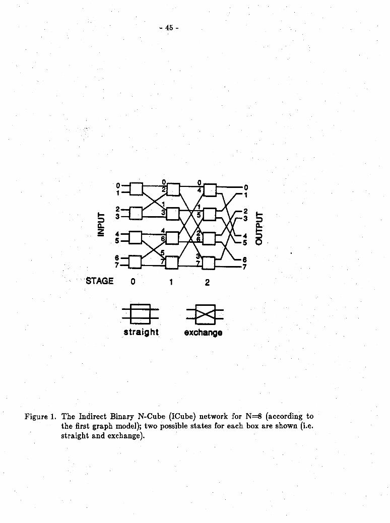
I-3CL
0,. 2j
STAGE
straight exchange
Figure 1. The Indirect Binary N-Cube (ICube) network for N=8 (according to the first graph model); two possible states for each box are shown (i.e. straight and exchange).

- 46 -
Figure 2. The IADM network for N=8 (according to the first graph model);tven{ and odd{ switches, 0 < * < 2, are enclosed with bold and regular edges respectively. The solid edges (links) show the ICube subgraph.

Figure 3. The Indirect Binary N-Cube (ICube) network for N=8 (according to the second graph model).
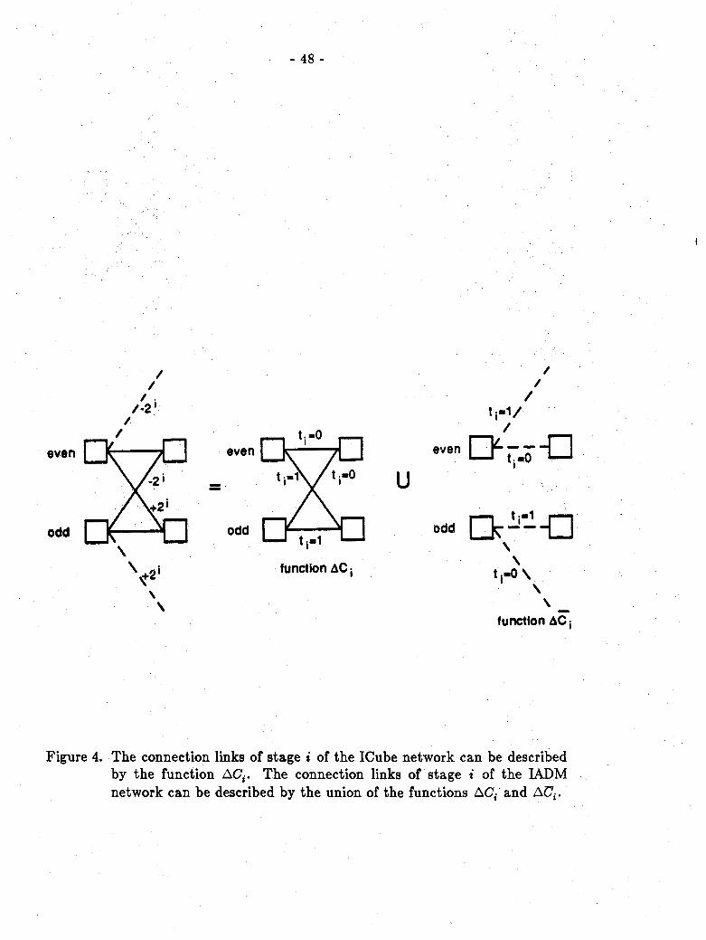
- 48 -
i
//
/ . /-2'
/
even even
function AC
\
tj-1/ /
uever, QL"“Q
oo- nkh--n
V\
tj-OX
function AC{
Figure 4. The connection links of stage t of the ICube network can be described by the function AC{. The connection links of stage i of the IADM network can be described by the union of the functions AC,-' and AC7,-.

- 49 -
Figure 5. Rerouting for a straight link blockage in (jES,- , j£Si+l). Path ({j+2'~k)eSi_k , jes{_k+1, • • • ,jesi+1) is a segment of the original path; {{j'+2i-k)G3i_k,{j+2i-k+1)G5i_k+l, ••• , (i+2,')£5< , jeSi+l) and ((i+2-fc)£5,_, , (i+2*-fc+1)€5,_,+1 , • • • , (i+2*)eS,. , (j+2*+1)ESI+1) are the rerouting paths for it.

- 50 -
Figure 6. Rerouting for a double nonstraight links blockage intieSi , (i-2’)€5i+1) and U^St »(i+2‘)€5i+i). Path
, (j+2*-fc+1)€5,._,+1 , • • • , (i+2*)G5,. , (j+2*)GS<+1) is arerouting path for both paths((j+2'-*)6S,-i > J^i-k+l > . ies,.+1, (i-2')es<+1) and(W+2‘-*)esu , j&i-k+l > • * • , iG*5i+1 , (i+2‘)€5i+1).

- 51 -
Figure 7. AH routing paths from 1£S0 to 0£S3 in an IADM network of size N=8.

- 52 -
AC:---------
STAGE 0 1 2
Figure 8. A cube subgraph generated by relabeling each switch j to (j'+l) mod 8 for an IADM network of size N=8.
OU
TPU
T

- 53 -
—O—D—
Figure 9. Rerouting for nonstraight output link blockages of switch j&Sq. The original path is ((j-2r)eSr , j£Sr+1, • • • , jeSq , {j~2q)eSq+1) and the nonstraight link found in backtracking is a positive link {(j-2r)esr ,j<ESr+1).