designofvirtualprivatenetworkswithmpls - … lucacittadini giuseppedibattista mauriziopatrignani...
TRANSCRIPT
Design of Virtual Private Networks with MPLS
Luca Cittadini Giuseppe Di Battista
Maurizio Patrignani
Summary
This chapter is devoted to Virtual Private Networks (VPNs) designed with MultiProtocol Label Switching (MPLS) [2, 3, 1], one of the most elusive protocolsof the network stack. Saying that MPLS is “elusive” is not overemphasizing:starting from its arduous fitting within the ISO/OSI protocol stack, continu-ing with its entangled relationships with several other routing and forwardingprotocols (IP, OSPF, MP-BGP, just to name a few), and ending with the com-plex technicalities involved in its configuration, MPLS defies classifications andchallenges easy descriptions.
On the other hand, and in a seemingly contradictory way, the configurationof VPNs with MPLS is rather simple and elegant, the complexity of the opera-tions being somehow hidden to the network operators themselves. Also, MPLSflexibility and easiness of maintenance make it a powerful tool, and account forits ubiquity in Internet Service Providers’ networks.
The chapter is organized as follows. Section 1 gives a brief introduction andmotivation to the concept of Virtual Private Network and explains why Layer3 MPLS VPNs are by far the most popular widespread kind of VPNs deployedtoday.
In Section 2 we introduce the reader to basic concept and terminology aboutLabel Switching (also known as Label Swapping) and Virtual Private Networks.
Section 3 gives a high-level step-by-step description of an MPLS VPN. Sucha description is based on three main ingredients: an any-to-any IP connectivityinside the network, a signalling mechanism to announce customer IP prefixes,and an encapsulation mechanism, based on MPLS, to transport packets acrossthe network.
Section 4 explores in detail the complex interplay between IP and MPLSthat is at the basis of MPLS VPNs.
More technical details about dynamic routing and connecting to the Internet,advanced usage of routing, ToS, TTL, and MTU are provided in Section 5.
The reader who is interested in getting only an intuition on how MPLS VPNswork can read Sections 1, 2, and 3. An indepth view of MPLS VPNs can begained by reading Sections 4 and 5.
1

Contents
1 Virtual Private Networks 3
1.1 The Need for Virtual Private Networks . . . . . . . . . . . . . . . 31.2 Layer 3 VPNs and MPLS . . . . . . . . . . . . . . . . . . . . . . 4
2 Background and Terminology 5
2.1 Label Switching . . . . . . . . . . . . . . . . . . . . . . . . . . . . 62.2 MPLS header and terminology . . . . . . . . . . . . . . . . . . . 8
3 Checkmate VPNs in Three Moves 10
3.1 Move 1 – Any-to-any IP connectivity among PEs . . . . . . . . . 113.2 Move 2 – Use BGP to distribute customer prefixes . . . . . . . . 143.3 Move 3 – Use MPLS encapsulation among PEs . . . . . . . . . . 15
4 An Indepth View of MPLS VPNs 16
4.1 IP Data Plane . . . . . . . . . . . . . . . . . . . . . . . . . . . . 164.2 MP-BGP Control Plane . . . . . . . . . . . . . . . . . . . . . . . 174.3 MPLS Control and Data Plane . . . . . . . . . . . . . . . . . . . 20
5 Advanced Topics 25
5.1 Dynamic Routing and Connecting to the Internet . . . . . . . . . 255.2 Designing Complex VPNs . . . . . . . . . . . . . . . . . . . . . . 265.3 ToS, TTL, and MTU . . . . . . . . . . . . . . . . . . . . . . . . . 28
6 Wrap-up and Conclusions 28
2

1 Virtual Private Networks
After giving a brief introduction and motivation to the concept of Virtual PrivateNetwork, this section explains why Layer 3 MPLS VPNs are by far the mostpopular widespread kind of VPNs deployed today.
1.1 The Need for Virtual Private Networks
The concept of Virtual Private Networks (VPNs) is essential in today’s net-works and will probably become paramount in tomorrow’s networks, yet mostpopular networking textbooks neglect the topic of VPNs because it is consideredtoo advanced to be covered in a networking course. This apparently contrastswith the simplicity of the concept of a VPN: in its most generic acception, aVPN is a closed (“Private”) group of nodes that want to be connected in anetwork (“Network”) and are willing to use virtual connections, or pseudowires(“Virtual”) instead of physical connections. Despite being seemingly very easy,each of the three keywords that appear in the definition hides a fair amount ofcomplexity that is not obvious at first glance.
Virtual Where in the ISO/OSI stack does virtualisation happen?
Private Is there any authentication mechanism? Does the VPN need to pre-serve confidentiality of the messages?
Network What does the network topology look like?
Each of these questions has many possible answers, which is the reason whythere are so many different types of VPNs in today’s networks. For example, apeer-to-peer network is a VPN where pseudowires are transport sessions, thereis no authentication amongst nodes and no traffic encryption, and the topologyof the network is defined by a dynamic algorithm. At the opposite side of thespectrum we have optical networks, where pseudowires are light paths throughoptical switching devices, there is no authentication and no encryption, and thenetwork topology is defined by simply configuring arbitrary pseudowires amongthe nodes.
The most important feature of a VPN is what virtualisation technique is usedand at which layer of the protocol stack. In general, pushing virtualisation downto the lower layers of the protocol stack (e.g., the physical or data-link layer)implies a higher implementation cost compared to the higher layers (e.g., thetransport or application layer). For example, deploying an optical network tobe able to run arbitrary pseudowires between two computers is several orders ofmagnitude more expensive than connecting those two computers to the Internetand writing a software that establishes a tunnel between them. On the otherhand, virtualising lower layers in the stack allows us to provide a richer featureset and has the advantage of being transparent to upper layer protocols. Alayer 2 VPN (L2VPN) transports packets of a specific layer 2 protocol and hence,thanks to the layered architecture of the protocol stack, is capable of supporting
3

any kind of layer 3 protocol. Analogously, a layer 3 VPN (L3VPN) transportspackets of a specific layer 3 protocol and hence is capable of supporting anykind of layer 4 protocol.
1.2 Layer 3 VPNs and MPLS
Layer 3 VPNs are by far the most popular widespread kind of VPNs deployedtoday. One reason is that layer 3 offers a good trade-off between deploymentcost and transparency to end hosts. Another, perhaps stronger reason is that,as the Internet converged towards today’s everything-over-IP scheme, it seemednatural to virtualise at the highest layer that supports transporting IP packets1.
Despite a variety of technologies provide virtual layer 3 services, most L3VPNsare based on the Multi Protocol Label Switching protocol (MPLS). The reasonwhy MPLS is so popular with respect to competing technologies is that it meetsthe demands of customers, providers, and vendors:
Customers’ needs: Customers (e.g., private companies, public administra-tions, etc.) have several geographically distributed sites and would like tohave a unique IP network connecting all of them. Besides mere connec-tivity, they have other requirements: (i) they want to keep their own IPaddressing plan for all the sites; (ii) they want their traffic to be logicallyseparated from the traffic of other customers that happen to use the sameshared infrastructure; and (iii) they want guaranteed quality of service.
Providers’ targets: Providers have invested lots of resources in building theirown network backbone. Since they have an existing infrastructure withmany distributed PoPs (Points of Presence) connected to the backbone,they would rather sell pseudowires rather than physical connections totheir customers. Among multiple techniques to implement pseudowires,providers prefer those that involve lower configuration efforts, which usu-ally implies lower maintenance costs. Moreover, they want the imple-mentation to be scalable with respect to the number of customers: theperformance of the network should only depend on the actual traffic, noton the number of supported VPNs or on the number of supported sites.
Vendors’ strategies: No network technology can be easily deployed withoutmeeting the strategies of network device producers and vendors, whoseimmediate aim is to sell many machines (possibly expensive carrier-graderouters) and, in the long run, to drive the shift from a variety of oldtechnologies for VPNs (e.g., ATM or Frame Relay) to new technologiesthat are simpler to manage and hence have the potential to grow thevendor’s market share.
1We are recently observing a similar convergence trend at layer 2 with Ethernet: conse-quently, in the last few years there has been a significant increase in the demand of virtuallayer 2 services.
4

Figure 1: The sample network used throughout this chapter.
Throughout this chapter we will refer to a very simple network (see Fig. 1) wherea provider has a network infrastructure with three PoPs (in Turin, Milan, andRome) and offers connectivity to two customers. Customer 1 has two sites andhas an IP addressing plan that allocates the 212.102.68.0/24 to its site in Milanand the 212.102.67.0/24 to its site in Rome. Customer 2 has two sites too andhas an IP addressing plan that allocates the 192.192.173.0/24 to its site in Turinand the 193.192.172.0/24 to its site in Rome.
We will use the sample network to illustrate each of the concepts introducedin this chapter. The text that describes and refers to the sample network willbe framed into shaded boxes like the one that encloses this paragraph.
2 Background and Terminology
In this section we introduce the reader to basic concept and terminology aboutLabel Switching (also known as Label Swapping) and Virtual Private Networks.
Throughout the chapter, we extensively refer to two tightly related yet dis-tinct concepts: forwarding and routing. Forwarding is the process of receiv-ing a packet from a network interface and deciding on which interface thatpacket should be sent. Usually, in order to minimize the latency of traversinga router, the decision about where to forward a packet is taken based on somepre-computed data structure. The simplest and most popular data structurethat fits this purpose is a table (the so-called forwarding table). Routing is theprocess by which each router builds its forwarding table and adapts it as thenetwork topology changes over time.
Correspondingly, we have forwarding and routing protocols, where the form-ers describe the formatting rules for network packets and the conventions thatrouters and hosts have to follow in order to exchange them, while the latter
5

Destination address Egress interface
10.100.100.22 en210.100.200.123 en1
Table 1: Structure of the forwarding table in the “forwarding by network ad-dress” approach.
Figure 2: A label switching network (where labels are not swapped at each hop).
describe packet formats and conventions used to exchange routing informationamong routers in order to compute their forwarding tables.
Finally, standard network terminology distinguishes between the correspond-ing router’s software layers. Namely, the layer where the forwarding processtakes place is called data plane or forwarding plane, while the layer where therouting process is managed is called control plane.
2.1 Label Switching
Traditionally, there are two different approaches to packet forwarding, each map-ping to a specific structure of the forwarding table. They are called forwarding
by network address and label switching.The most intuitive approach is forwarding by network address, that is the
approach of IP. When a packet arrives at a router, the router parses the desti-nation address from the packet header and looks it up in its forwarding table.The forwarding table has a simple 2-column structure where each row maps adestination address to the egress interface that the packet should be forwardedto (see Table 1). For scalability and efficiency reasons, it is possible to aggregateseveral destination addresses sharing the same egress interface into a single row.
An alternative approach is known as label switching, that is the approachof MPLS. Essentially, while forwarding by network address requires that theegress interface be chosen based on the destination of the packet, label switchingrequires that such an interface be chosen based on the flow the packet belongsto, where a flow corresponds to an instance of transmission, i.e., a set of packets,from a source to a destination and is identified by a tag (called label) attachedto each packet of the flow.
When the packet arrives at a router, the router extracts (pops) the label from
6

Figure 3: A label switching network (where labels are swapped at each hop).
Incoming interface Incoming label Egress interface Egress label
en2 101 en5 218
Table 2: Structure of the forwarding table in the “forwarding by label swapping”approach with per-interface label scope.
the header, looks the label value up in its forwarding table, and finds (i) theegress interface the packet should be forwarded to, and (ii) a new label to apply(push) to the packet.
A forwarding process based on labels rather than destination addresses poseschallenges to the corresponding routing protocols. In fact, the instances of flowtraversing the network are much more volatile than the addressing scheme usedto identify their destinations. Before transmitting a new flow, a route from itssource to its destination has to be computed and a new label has to be assignedto each leg of the route. In order to facilitate the task of picking a new, unused,label, labels are not required to be unique for the entire network but are requiredto be unique for each router or for each interface only. This is why they haveto be changed at each hop. Depending on whether labels have a per-interfaceor per-router scope, the forwarding table is structured as in Table 2 or Table 3,respectively.
As an example, Fig. 2 shows a label switching network where each flow hasan associated label (labels are represented with colors) that is unique for theentire network. If the label switching technologies followed the approach ofFig. 2 they would have the advantage that labels have not to be swapped ateach hop. On the other hand, if they did this choice they would have the bigdrawback of requiring a centralized control of the assigned labels. Fig. 3 showswhat actually happens in label switching networks, where labels are swapped
Incoming label Egress interface Egress label
101 en5 218
Table 3: Structure of the forwarding table in the “forwarding by label swapping”approach with per-router label scope.
7
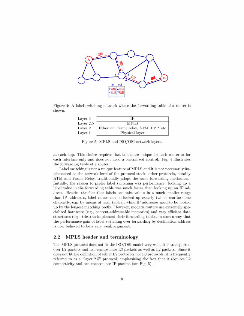
Figure 4: A label switching network where the forwarding table of a router isshown.
Layer 3 IPLayer 2.5 MPLSLayer 2 Ethernet, Frame relay, ATM, PPP, etcLayer 1 Physical layer
Figure 5: MPLS and ISO/OSI network layers.
at each hop. This choice requires that labels are unique for each router or foreach interface only and does not need a centralized control. Fig. 4 illustratesthe forwarding table of a router.
Label switching is not a unique feature of MPLS and it is not necessarily im-plemented at the network level of the protocol stack: other protocols, notablyATM and Frame Relay, traditionally adopt the same forwarding mechanism.Initially, the reason to prefer label switching was performance: looking up alabel value in the forwarding table was much faster than looking up an IP ad-dress. Besides the fact that labels can take values in a much smaller rangethan IP addresses, label values can be looked up exactly (which can be doneefficiently, e.g. by means of hash tables), while IP addresses need to be lookedup by the longest matching prefix. However, modern routers use extremely spe-cialized hardware (e.g., content-addressable memories) and very efficient datastructures (e.g., tries) to implement their forwarding tables, in such a way thatthe performance gain of label switching over forwarding by destination addressis now believed to be a very weak argument.
2.2 MPLS header and terminology
The MPLS protocol does not fit the ISO/OSI model very well. It is transportedover L2 packets and can encapsulate L3 packets as well as L2 packets. Since itdoes not fit the definition of either L2 protocols nor L3 protocols, it is frequentlyreferred to as a “layer 2.5” protocol, emphasizing the fact that it requires L2connectivity and can encapsulate IP packets (see Fig. 5).
8

Label ToS S TTL
20 bits 8 bits3 1
Figure 6: Structure of a record in an MPLS header.
When a pure IP packet needs to be transported over an MPLS network, thefirst MPLS-enabled router in the network adds an MPLS header in between theL2 header and the IP header. The MPLS header consists of a stack of 4-byterecords where each record has the following structure (depicted in Fig. 6):
• a label field (20 bits), which carries the label value;
• a ToS field (3 bits) which is used to discriminate different levels of qualityof service (QoS) and to carry explicit congestion notifications (ECN);
• a bottom-of-stack field (1 bit) which is set to 1 when the record is thelast record in the stack; and
• a TTL field (8 bits) which is decremented at each hop, similarly to theTTL field in the IP header.
When an MPLS-enabled router receives a packet, it can perform three dif-ferent operations: (i) push a label onto a (possibly empty) stack, (ii) pop a labelfrom the stack (possibly resulting in an empty stack), or (iii) switch the toplabel of the stack, which can be seen as a pop operation followed by a pushoperation. MPLS-VPN terminology uses specific names to distinguish routersthat do not understand labels at all, routers that push (or pop) labels, androuters that simply switch labels.
Routers belonging to the first group are called customer edge (CE) routersbecause they are not MPLS-enabled. Typically those are the customer’s routersthat need to be interconnected via an L3VPN. CE routers can only handle IPpackets and are not aware of the MPLS layer which is used to implement theVPN.
Routers belonging to the second group are called provider edge (PE) routers,or label edge routers (LERs). They are placed at the edge of the MPLS backboneof the provider, have direct connectivity to the CE routers, and act as the accesspoint of the customer to the VPN. While they need to be able to perform labelswitch operations because they are part of the backbone, they spend most theirtime pushing labels (when an IP packet comes from a CE router) and poppinglabels (when an MPLS packet needs to be forwarded to a CE router).
Routers belonging to the third group are called provider (P) routers, orlabel switch routers (LSRs). They are in the core of the MPLS network. Sincethey do not interact directly with non-MPLS routers, they mainly perform labelswitching operations in order to forward packets to other MPLS routers.
9

Figure 7: Inside the provider’s infrastructure.
Fig. 7 shows some details of the provider’s infrastructure. It is both an MPLSnetwork and an IP network (it has an MPLS data plane and an IP data plane).
If we look at it from the MPLS point of view, we can distinguish CE, PE, andP routers. The small, red routers placed in the customer cloud at the cornersof Fig. 7 are CE routers. CE routers are directly attached to the blue routersat the edge of the provider cloud, which are the PE routers (or LERs). Finally,the grey routers in the core of the provider network are the P routers (or LSRs).
Since the provider netwok is also an IP network an IP address is given to theinterfaces. To do this, our provider exploits prefix 80.0.0.0/8. This prefix willnot be announced outside the provider’s network. The reason for the presence oflabel AS100 in the cloud enclosing the provider infrastructure will be explainedsoon.
Fig. 7 puts also in evidence that the sites of Customer 1 should be connectedthrough a VPN called VPN1 and the sites of Customer 2 should be connectedthrough a VPN called VPN2.
3 Checkmate VPNs in Three Moves
In this section we give a high-level description of an MPLS VPN. Such a de-scription is based on three main ingredients that we call “moves”. We claimthat a reader that understands these three moves will be able to checkmate thiscomplex matter.
From the perspective of the customer, an MPLS VPN is nothing more thana cloud which is transparent to IP packets: as if the customer’s CE routerswere connected by a pseudowire which traverses the cloud. It is tempting toimplement such a pseudowire using a tunnel (e.g., GRE or IPSec) between PErouters where the customer packets travel across the cloud encapsulated into IP
10

or IPSec packets. However, as the number of interconnected sites grows, man-ually managing configured tunnels and maintaining forwarding tables becomesexcessively complex. For example, if we were to use tunnels to implement anL3VPN over 5 customer sites, a full-mesh topology would translate to 20 man-ually configured tunnels. Moreover, if the customer adds a new subnet to oneof its sites, we need to update the forwarding tables of all our 5 PE routers.
The intrinsic problem with tunnels is that they rely on a pre-determinedendpoint which is configured at tunnel setup time. Ideally, we would like totake advantage of the benefits of encapsulation without dealing with the issueof knowing the tunnel endpoint in advance. Namely, we would like packets tobe encapsulated at the ingress PE and decapsulated at egress PE. We can splitthis goal into three high-level steps that we call moves:
Move 1: Achieve any-to-any IP connectivity among PEs,
Move 2: Define a signalling mechanism to distribute customer prefixes amongPEs, and
Move 3: Define an encapsulation mechanism to transport packets from a PE toanother across the network.
One of the key benefits of using encapsulation (Move 3) is that the complexityof configuring L3VPNs for customers is confined to PEs. The core of the network(i.e., P routers) does not need to know anything about customer prefixes: itsimply needs to know how to transport packets from a PE to another (Move 1).This means that the size of the forwarding table of P routers depends on thenumber of PE routers rather than on the number of customer prefixes. Finally,if PE routers use a signalling mechanism to dynamically synchronize the listof customer prefixes, the only pieces of information that need to be manuallyconfigured at each PE are the L3VPN identifier and the IP address of the CErouter.
In the following we elaborate each move in more detail.
3.1 Move 1 – Any-to-any IP connectivity among PEs
The first move is actually quite simple. It is nothing more than what anyInternal Gateway Protocol (IGP) is designed to achieve: seamless, redundantand dynamic IP-level any-to-any connectivity. Since PEs are our encapsulationendpoints, we want them to be reachable independent of the availability ofspecific network interfaces. In other words, we do not want to use the IP addressof physical interfaces for PEs, but loopback addresses. Hence, to fulfill Move 1we simply assign a loopback address to each PE router and use an IGP (e.g.OSPF or IS-IS) to ensure any-to-any connectivity among loopback addresses.
11

Figure 8: Loopbacks of PEs.
Figure 9: IP connectivity for LER1.
Figure 10: IP connectivity for LSR2.
12
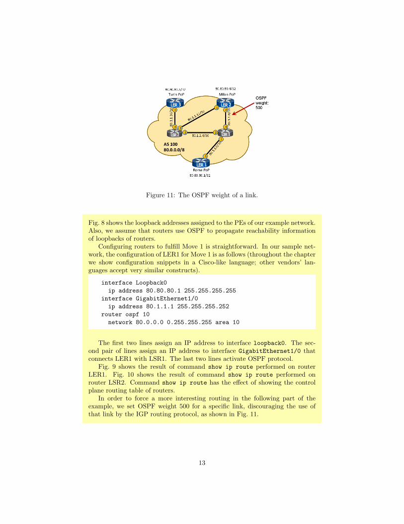
Figure 11: The OSPF weight of a link.
Fig. 8 shows the loopback addresses assigned to the PEs of our example network.Also, we assume that routers use OSPF to propagate reachability informationof loopbacks of routers.
Configuring routers to fulfill Move 1 is straightforward. In our sample net-work, the configuration of LER1 for Move 1 is as follows (throughout the chapterwe show configuration snippets in a Cisco-like language; other vendors’ lan-guages accept very similar constructs).
interface Loopback0
ip address 80.80.80.1 255.255.255.255
interface GigabitEthernet1/0
ip address 80.1.1.1 255.255.255.252
router ospf 10
network 80.0.0.0 0.255.255.255 area 10
The first two lines assign an IP address to interface loopback0. The sec-ond pair of lines assign an IP address to interface GigabitEthernet1/0 thatconnects LER1 with LSR1. The last two lines activate OSPF protocol.
Fig. 9 shows the result of command show ip route performed on routerLER1. Fig. 10 shows the result of command show ip route performed onrouter LSR2. Command show ip route has the effect of showing the controlplane routing table of routers.
In order to force a more interesting routing in the following part of theexample, we set OSPF weight 500 for a specific link, discouraging the use ofthat link by the IGP routing protocol, as shown in Fig. 11.
13

Figure 12: Use of BGP to distribute customer prefixes.
3.2 Move 2 – Use BGP to distribute customer prefixes
In order to distribute reachability information about customer prefixes, MPLSrelies on a variant of BGP called Multi-Protocol BGP (MP-BGP). PE routersestablish a full-mesh of iBGP peerings and each PE announces to all the otherPEs the customer prefixes that it can reach via the CE router it is connectedto. The Multi-Protocol extension to BGP is needed to introduce the conceptof the “customer” (i.e., the “L3VPN identifier”) which does not exist in plainBGP.
Compared with any ad-hoc signalling mechanism that could have been de-signed specifically for MPLS, the choice of using BGP has the advantage ofrelying on a well-known protocol and thus making the learning curve smootherfor practitioners. Moreover, BGP has built-in mechanisms (e.g., route reflec-tion) to be able to scale as the number of PE routers increases.
Fig. 12 shows an high-level illustration of how the BGP peerings with LER3and LER2 can be used by LER1 to announce customer prefixes.
Configuring MP-BGP peerings is very similar to configuring plain iBGP peer-ings. Consider the following snippet from the configuration of router LER1:
14

router bgp 100
neighbor 80.80.80.4 remote-as 100
neighbor 80.80.80.4 update-source Loopback0
neighbor 80.80.80.5 remote-as 100
neighbor 80.80.80.5 update-source Loopback0
!
address-family vpnv4
neighbor 80.80.80.4 activate
neighbor 80.80.80.5 activate
exit-address-family
The first line starts the BGP configuration and states that the router belongsto AS100. Observe that all the routers are supposed to belong to AutonomousSystem (AS) 100. This AS number will not be necessarily propagated outsidethe provider’s network and is only needed to establish peerings between PEs.
The following lines specify the BGP peerings. The presence of the “vpnv4”address family identifies LER2 and LER3 as MP-BGP neighbors of LER1.
3.3 Move 3 – Use MPLS encapsulation among PEs
Having performed Move 1 and Move 2, a PE router r is able to select the PErouter r′ that is connected to a given customer prefix (by Move 2). Also, ris able to forward IP packets to r′ (by Move 1). The only piece missing isan encapsulation mechanism to transport IP packets from r to r′. One suchencapsulation mechanism is MPLS: the PE router r encapsulates the IP packetby pushing two MPLS labels. The label at the top of the stack (outer label)is switched by P routers in order to deliver the packet to router r′. The labelat the bottom of the stack (inner label) is left untouched and it is used bythe egress PE r′ to identify the correct L3VPN. Observe that the inner labelis necessary because r and r′ could serve a variety of customers, and addressspaces might be overlapping. For instance, routers r and r′ could be serving twodistinct VPNs for two customers, both using addresses in the RFC 1918 space.
Let us briefly recap how a packet is delivered across an MPLS cloud. WhenPE router r receives a packet from a CE router, it picks the VPN identifierand the destination address and looks up to find which PE the packet shouldbe delivered to. In our running example, the PE router is r′. Then, r pushesthe VPN identifier as the inner MPLS label and pushes an outer label which isguaranteed to deliver the packet to r′. How does r pick this outer label?
The outer label that maps to router r′ is determined by the Label ForwardingInformation Base (LFIB) of r, which is the forwarding table for MPLS.
The task of distributing labels and maintaining the LFIB of label switch
15

routers is performed by the Label Distribution Protocol (LDP)2. In its simplestform, LDP is able to setup a Label Switch Path (LSP) from a PE to anotherby simply importing the nexthop from the IP data plane (remember Move 1)at each intermediate hop.
It is extremely simple to configure a router to fulfill Move 3, because the LDPprotocol can be safely run in the default configuration, and enabling MPLSencapsulation on specific interfaces is a single command. The configuration ofLER1 for Move 3 is as simple as the following.
mpls label protocol ldp
interface GigabitEthernet1/0
ip address 80.1.1.1 255.255.255.252
mpls ip
4 An Indepth View of MPLS VPNs
We have seen that the architecture of MPLS VPNs builds upon three buildingblocks: a working IP data plane that is capable of interconnecting the loopbackaddresses of PE routers, a BGP-based control plane to distribute reachabilityinformation about customer prefixes, and MPLS encapsulation among PEs.
While the first building blocks might seem straightforward at a first glance,there are a number of details which complicate the big picture but neverthelessare important in order to grasp the internals of MPLS VPNs.
4.1 IP Data Plane
IP connectivity between PE routers is easy to achieve using any suitable routingprotocol. However, while IP connectivity is enough for all P routers to find apath towards PE routers, it is not sufficient for the PE routers themselves, asthey are also responsible for pushing and popping labels. In fact, the PE dataplane must also fulfill the challenging objective to map a CE to its specificVPN. The difficulty of this task is due to the fact that a PE router might beattached to a number of CEs of different customers, and must ensure that eachCE is mapped to the correct VPN, even in presence of overlapping customers’address spaces. To accomplish this task, MPLS VPNs exploit a technique calledVirtual Routing and Forwarding (VRF) which allows a router to have multiple(virtual) routing tables, potentially a separate virtual routing table for eachnetwork interface (either physical or logical). With this technique, mapping aCE to the correct VPN is as easy as configuring the corresponding interfacewithin a specific VRF table.
2Alternative protocols such as RSVP and BGP can also serve the same purpose, but areout of the scope of this chapter.
16
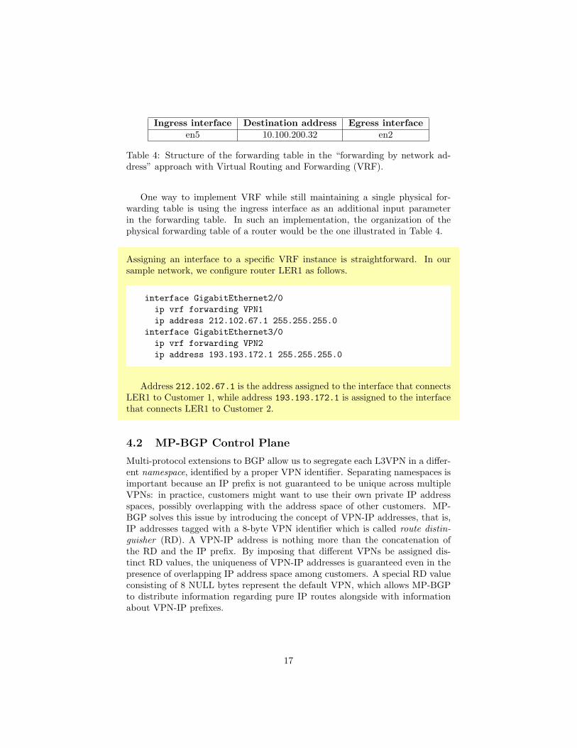
Ingress interface Destination address Egress interface
en5 10.100.200.32 en2
Table 4: Structure of the forwarding table in the “forwarding by network ad-dress” approach with Virtual Routing and Forwarding (VRF).
One way to implement VRF while still maintaining a single physical for-warding table is using the ingress interface as an additional input parameterin the forwarding table. In such an implementation, the organization of thephysical forwarding table of a router would be the one illustrated in Table 4.
Assigning an interface to a specific VRF instance is straightforward. In oursample network, we configure router LER1 as follows.
interface GigabitEthernet2/0
ip vrf forwarding VPN1
ip address 212.102.67.1 255.255.255.0
interface GigabitEthernet3/0
ip vrf forwarding VPN2
ip address 193.193.172.1 255.255.255.0
Address 212.102.67.1 is the address assigned to the interface that connectsLER1 to Customer 1, while address 193.193.172.1 is assigned to the interfacethat connects LER1 to Customer 2.
4.2 MP-BGP Control Plane
Multi-protocol extensions to BGP allow us to segregate each L3VPN in a differ-ent namespace, identified by a proper VPN identifier. Separating namespaces isimportant because an IP prefix is not guaranteed to be unique across multipleVPNs: in practice, customers might want to use their own private IP addressspaces, possibly overlapping with the address space of other customers. MP-BGP solves this issue by introducing the concept of VPN-IP addresses, that is,IP addresses tagged with a 8-byte VPN identifier which is called route distin-
guisher (RD). A VPN-IP address is nothing more than the concatenation ofthe RD and the IP prefix. By imposing that different VPNs be assigned dis-tinct RD values, the uniqueness of VPN-IP addresses is guaranteed even in thepresence of overlapping IP address space among customers. A special RD valueconsisting of 8 NULL bytes represent the default VPN, which allows MP-BGPto distribute information regarding pure IP routes alongside with informationabout VPN-IP prefixes.
17

Figure 13: How MP-BGP can distribute per-VPN reachability information.
It is easy to assign an RD value to a single VRF instance:
ip vrf VPN1
rd 100:11
ip vrf VPN2
rd 100:22
Fig. 13 shows the output of command show ip bgp vpnv4 all on routerLER1. This command has the same effect of show ip bgp but it shows therouting entries related to IPv4 VPNs. In this case the output puts in evidencethat LER1 knows two prefixes. Namely, it knows 212.102.68.0 with Route Dis-tinguisher 100:11 and 193.192.173.0 with Route Distinguisher 100:22.
Tagging IP prefixes with a VPN identifier is an easy solution, but it is sub-optimal in a specific use case which has seen increasing popularity recently: theso-called extranets. In its simple definition, an extranet is simply a connectionbetween two different VPNs that are guaranteed to have non-overlapping IPaddress spaces. A realistic example might be a specific site of one customerthat needs to connect to another specific site of another customer. A naive im-plementation of extranets would define an ad-hoc VPN and assign it a new RDvalue. However, this solution is undesirable because it creates multiple VPNsthat have duplicate entries, yielding a waste of router memory (to store theentries) and a waste of router’s CPU time (to process update messages that areidentical but for the RD value).
In order to overcome such limitations, MPLS decouples the concept of routedistinguisher, which is used to segregate the address space in multiple names-paces, from the concept of route target (RT) which is another tag that is used to
18
control which routes are imported in a given VPN and, similarly, which routesare exported from a given VPN. The route target is transported by MP-BGPby means of extended communities. More precisely, by exporting a route from aVPN we attach a user-defined RT community to all VPN-IP prefixes belongingto that VPN. On the other hand, by importing a given RT into a VPN we acceptthat every route having that RT value will be visible from the devices in thatVPN.
Each VRF instance can be configured to import or export routes labelled witha specific Route Target value. In our simple example, assuming that no ex-tranet connectivity is required between Customer 1 and Customer 2, each VRFinstance can simply import a single RT value, as the following configurationsnippet of LER1 shows:
ip vrf VPN1
rd 100:11
route-target export 100:1000
route-target import 100:1000
ip vrf VPN2
rd 100:22
route-target export 100:2000
route-target import 100:2000
This means that all the prefixes of VPN1 announced via MP-BGP by LER1to any other PE are tagged with RT 100:1000. Also, any prefix that is tagged100:1000 and is announced to LER1 via MP-BGP is imported into the VRF ofVPN1. The configuration for VPN2 is similar.
Route Targets provide network operators with the flexibility of leaking specificroutes into specific VRF instances, easing the deployment of extranets. RouteTargets are transported in MP-BGP messages as extended BGP communities.For this reason, the configuration of MP-BGP peers needs to specify that thepeer supports extended communities (which are disabled by default).
router bgp 100
address-family vpnv4
neighbor 80.80.80.4 activate
neighbor 80.80.80.4 send-community both
neighbor 80.80.80.5 activate
neighbor 80.80.80.5 send-community both
exit-address-family
19

Figure 14: An MP-BGP signaling packet captured over the network.
To better understand the interplay between MP-BGP and the Route Targets,let us give a look at the content of an MP-BGP packet captured in our network(see Fig. 14). Observe how the route target in the blue frame is contained inthe extended communities.
The announcements tells to the MP-BGP peer receiving it that the packetsthat will be received with the inner MPLS label 24 (red frame in the picture) willrefer to the specified route target and the specified route distinguisher (greenframe in the picture).
4.3 MPLS Control and Data Plane
The task of MPLS control plane is simply to establish Label Switched Paths(LSPs) between the loopback addresses of PE routers. LDP is in charge ofpopulating and maintaining routers’ LFIBs that implement the LSPs. In itsmost popular distribution mode, called unsolicited downstream, LDP works inthe following way. Each router creates a label for locally originated prefixes (e.g.,the loopback address). The binding between a label and a locally originatedprefix is called a local binding. By contrast, a remote binding is a bindingbetween a label and a remotely originated prefix. Each router starts flooding itslocal bindings. When a neighboring router receives a binding for prefix p1 andlabel l1 on interface i1, it looks up its IP forwarding table to check whether theadvertised prefix is routed on interface i1. If this is the case, it picks anotherlabel l2 and starts announcing a binding for p1 and l2. Meanwhile, it updatesits LFIB with the tuple < l2, l1, p1, i1 >. This means that when a packet arrivesthat is labelled l2, the LFIB will swap l2 with l1 and deliver it via interface
20

Figure 15: The MPLS forwarding table of LER1.
Figure 16: The MPLS forwarding table of LSR1.
i1. This assumes per-router label scope, which is the default for most routervendors. In per-interface label scope, the router can simply advertise differentlabels for each interface, and enrich the LFIB accordingly.
Regarding MPLS data plane, we have already seen that the ingress PE routerlooks up to find the loopback address of the egress PE router, looks up its LFIBto select the outer label, and then encapsulate the received IP packet by pushingthe inner and the outer MPLS labels. The packet is then label-switched acrossthe MPLS network to the egress PE router using the bindings found in the LFIBof each router. As an optimization, the penultimate router, i.e., the router thatreceives a local binding from the egress PE, can pop the outer label, in sucha way that the egress PE router only receives the inner label and thereforeperforms a single lookup in its LFIB.
21

Figure 17: The MPLS forwarding table of LSR2.
Figure 18: An IP packet originated by the Rome site of Customer 1 reaches thePE router called LER1.
Figs. 15, 16, and 17 show the MPLS forwarding tables of some routers of ournetwork.
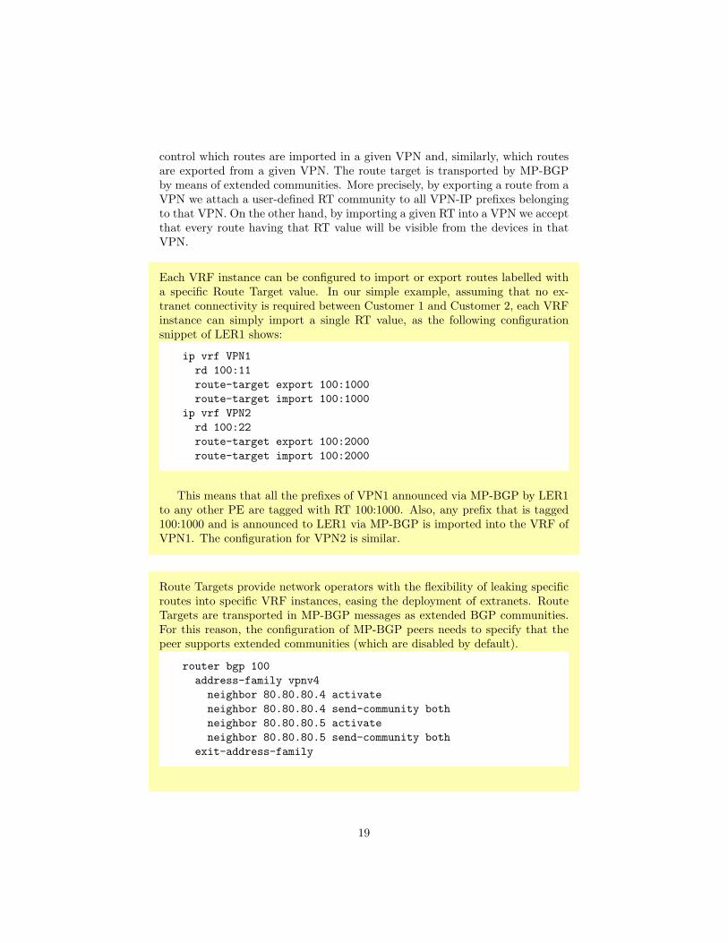
Figs. 18–23 illustrate the travel of a packet through our network.First, Fig. 18 shows what happens when an IP packet originated by the Rome
site of Customer 1 reaches the PE called LER1. Namely, it is encapsulated intoan MPLS packet with two labels and then sent to LSR1. The inner label (yellow)identifies the RT while the outer label (red) is the label used for the forwardingprocess.
Second (Fig. 19), the MPLS packet reaches LSR1, its outer red label is
22

Figure 19: An MPLS packet reaches the P router called LSR1.
Figure 20: An MPLS packet reaches the P router called LSR2.
Figure 21: An MPLS packet traveling to PE router LER2.
23
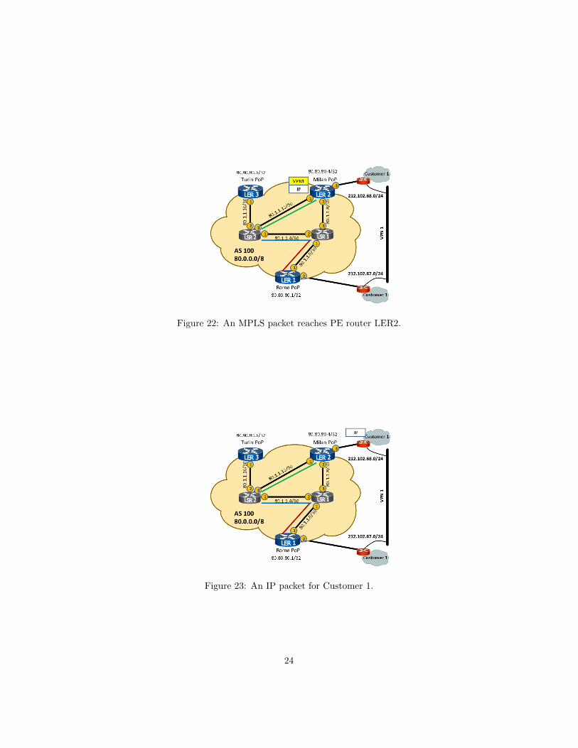
Figure 22: An MPLS packet reaches PE router LER2.
Figure 23: An IP packet for Customer 1.
24
replaced with a blue label, and the packet is forwarded to LSR2.Third (Figs. 20 and 21), the MPLS packet reaches LSR2. LDP makes LSR2
aware that it is the penultimate hop in the LSP. For this reason, LSR2 simplypops the outer label and forwards the packet to LER2.
Fourth (Fig. 22), the MPLS packet reaches LER2. LER2 notices that thereis only one MPLS label (which used to be the inner label), so the packet ismeant to be forwarded via IP in one of the VPNs that LER2 serves. LER2 usesthe RT label to identify the VRF instance, then looks up the IP destinationaddress in the VRF forwarding table.
Fifth (Fig. 23), the IP packet is delivered to its final destination.
5 Advanced Topics
In this section we give more technical details about dynamic routing and con-necting to the Internet, advanced usage of Route Targets, ToS, TTL, and MTU.
5.1 Dynamic Routing and Connecting to the Internet
So far we have not yet discussed how the PE router can learn the prefixes thatare served by its directly attached CE router. Of course, it is trivial to configurestatic routes on the PE, however this creates an undesirable coupling betweenthe provider and the customer: whenever the customer wants to add a differentIP subnet, it has to bother the provider to configure static routes before thatIP subnet is reachable from other customer sites in the same VPN.
The solution is to have the CE and the PE establish an eBGP peering wherethe CE announces its local networks, while the PE announces all the networksthat it learns in the same VPN. Observe that the, contrary to the MP-BGPpeerings among PEs, peerings between CEs and PEs are pure eBGP peering:the CE does not know anything about VPNs and route distinguishers. It isthe MP-BGP process on the PE router that takes care of processing the reach-ability information learned from the CE and updating the VPN reachabilityinformation accordingly.
A BGP peering between the CE and the PE also allows a CE in a VPNto announce a default route, causing all other sites in the same VPN to routeInternet traffic via that CE router. This might be an advanced is the customer’spolicy is to have Internet traffic passing through a centralized checkpoint (e.g.,a firewall or a proxy). However, this is not the only way to connect a VPN tothe Internet. For example, a PE might be configured to forward natively all thepackets from a CE which do not match any VPN route. Alternatively, the de-fault route might be given its own route target, and whenever a VPN site needsInternet access the PE simply imports that route target in the correspondingVPN routing table. We refer the reader to [2] for a discussion of alternatives toget Internet access within a VPN.
25

Figure 24: A configuration where a single customer has four sites: Site 2, 3, and4 are only allowed to exchange traffic with Site 1 in Rome.
In our sample network, our goal is to most common way to inject routeseBGP-learned routes in MP-BGP, tagging them with the correct RD value. Inorder to do this, it suffices to configure an eBGP peering in the context of aVRF instance, as the following configuration snippet of LER1 shows.
router bgp 100
address-family ipv4 vrf VPN1
neighbor 212.102.67.2 remote-as 65001
exit-address-family
!
address-family ipv4 vrf VPN2
neighbor 193.192.172.2 remote-as 65002
exit-address-family
5.2 Designing Complex VPNs
Sometimes more sophisticated configurations are needed. For example we mighthave a VPN where not all pairs of sites are allowed to exchange packets. A typi-cal situation is the so called hub-and-spoke configuration, where a customer hasa main site and several peripheral sites and the peripheral sites can communicateonly through the main site.
How to do this is illustrated in the following example.
26

A suitable use of Route Distinguishers and Route Targets allows sophisticatedconfigurations like the one shown in Fig. 24.
Suppose we choose the following Route Distinguishers for the four sites,where Rome is the main site and Turin, Milan, and Naples are the peripheralsites:
Turin: RD 100:1
Milan: RD 100:2
Rome: RD 100:3
Naples: RD 100:4
We can split the customer VPN into three VPNs. VPN1 is used to connectTurin with Rome, VPN2 is used to connect Milan with Rome, and VPN3 isused to connect Naples with Rome.
For each VPN we define a distinct Route Target:
VPN1: 100:1000
VPN2: 100:2000
VPN3: 100:3000
The configuration of peripheral sites, like for example Turin, is as follows:
ip vrf siteTurin
rd 100:1
route-target import 100:1000
route target export 100:1000
Rome’s PE configuration (the hub) is as follows:
ip vrf siteRome
rd 100:3
route-target import 100:1000
route target export 100:1000
route-target import 100:2000
route target export 100:2000
route-target import 100:3000
route target export 100:3000
In this way Rome imports all the Route Targets and exports all the RouteTargets and is hence able to communicate with all sites. On the other hand aperipheral site like Turin imports and exports Route targets only wrt to Romeand hence is able to communicate with Rome only.
27

5.3 ToS, TTL, and MTU
Whenever encapsulation of IP packets happens, there are three main questionsthat arise:
1. what happens to the ToS / DSCP information in the IP header that thecustomer might have set in order to properly prioritize traffic?
2. what happens to the TTL field in the IP header and how does encapsula-tion cope with forwarding loops?
3. how does encapsulation affect MTU for upper layer protocols?
Luckily, MPLS has an easy answer for the first two questions. Recall fromFig. 6 that MPLS has dedicated fields for ToS and TTL. When the ingress PErouter receives an IP packet from the CE router, it simply copies the valuesToS and TTL in the MPLS header. More precisely, a push operation impliescopying ToS and TTL from the IP header to the MPLS header. Conversely, apop operation implies copying the TTL value from the MPLS header back to theIP header. This way, the TTL continues to serve as a hop count3 even withinthe MPLS network, and P routers can honor the quality of service parametersrelated to the ToS field.
Regarding the third question, since an MPLS label takes 4 bytes and the PErouter pushes two of them, the MTU within the MPLS network should be atleast 8 bytes larger than the MTU that the CE is aware of. Given that modernOSes tend to perform path MTU discovery by default, MTU is becoming lessof an issue for MPLS deployments. Rewriting the MSS TCP options at the PErouter is also a common solution, even though it does not support UDP traffic.
6 Wrap-up and Conclusions
After having entered the details of MPLS VPNs, we are able to discuss theextent to which the goals that we stated in Section 1.2 are met.
By using Route Distinguishers and label stacks within the provider cloud,customers can retain their IP address plan and the traffic belonging to differentcustomers is properly segregated. Since MPLS is capable of transporting QoSinformation from the IP header, quality of service can also be guaranteed. More-over, the configuration of CE routers is completely unaware of MPLS-specificdetails.
Providers are able to keep the configuration in the core of the network ex-tremely simple and scalable: in fact, the configuration of P routers does notdepend on the number of deployed VPNs. Since the backbone is only con-cerned with transporting packets from a PE to another, the forwarding table of
3Observe that when the TTL in the MPLS header reaches 0 (e.g. in a traceroute), a Prouter does not know how to send the corresponding ICMP error back to the sender, becauseit lacks information about VPNs. A naive yet effective solution is to generate the ICMPpacket and label-switch it to the egress PE anyway. The egress PE (which has informationabout VPNs) will then send the ICMP packet back to the sender.
28

P routers only contains one entry for each loopback address, which makes for-warding performance independent of the number of VPNs. Configuring a newVPN implies modifying the configuration of the PE routers that are directlyconnected to the customer’s sites. Moreover, such a configuration boils downto assigning a unique RD and RT and establishing eBGP peerings with the CErouters.
Acknowledgments
We would like to thank Mario Cola and Massimo Rimondini for their help andfriendship.
References
[1] L. Andersson, I. Minei, and B. Thomas. LDP Specification. RFC 5036,2007.
[2] E.Rosen and Y. Rekhter. BGP/MPLS IP Virtual Private Networks (VPNs).RFC 4364, 2006.
[3] E.Rosen, A. Viswanathan, and R. Callon. Multiprotocol Label SwitchingArchitecture. RFC 3031, 2001.
29