designing the ares i crew launch vehicle upper stage ... · the ares [ team consists ofthe range...
TRANSCRIPT

Designing the Ares I Crew Launch VehicleUpper Stage Element and Integrating the Stack
at NASA's Marshall Space Flight Center
Garry Lyles, Associate Director for Technical ManagementNeil E. Otte, Ares Chief Engineer
Engineering DirectorateNASA Marshall Space Flight Center
.Huntsville, AL 35812
Abstract
Fielding an integrated launch vehicle system entails many challenges, not the least ofwhich is the fact thatit has been over 30 years since the United States has developed a human-rated vehicle - the venerable SpaceShuttle. Over time, whole generations of rocket scientists have passed through the aerospace commun ity without theopportunity to perform such exacting, demanding, and rewarding work. However, with almost 50 years ofexperience leading the design, development, and end-to-end systems engineering and integration of complex launchvehicles, NASA's Marshall Space Flight Center offers the in-house talent - both junior- and senior-level personnel- to shape a new national asset to meet the requirements for safe, reliable, and affordable space explorationsolutions.' These personnel are housed primarily in Marshall's Engineering Directorate and are matrixed into theprograms and projects that reside at the rocket center. Fortunately, many Apollo era and Shuttle engineers, as well asthose who gained valuable hands-on experience in the 1990s by conducting technology demonstrator projects suchas the Delta-Clipper Experimental Advanced, X-33, X-34, and X-37, as well as the short-lived Orbital Space Plane,work closely with industry partners to advance the nation's strategic capability for human access to space. Currently,only three spacefaring nations have this distinction, including the United States, Russia, and, more recently, China.The U.S. National Space Policy of2006 directs that NASA provide the means to travel to space, and the NASAAppropriations Act of2005 provided the initial funding to begin in earnest to replace the Shuttle after theInternational Space Station construction is complete in 20 IO? These and other strategic goals and objectives aredocumented in NASA's 2006 Strategic Plan.3
In 2005, a team of NASA aerospace experts conducted the Exploration Systems Architecture Study, whichrecommended a two-vehicle approach to America's next space transportation system for missions to theInternational Space Station in the next decade and to explore the Moon and establish an outpost around the 2020timeframe.4 Based on this extensive study, NASA selected the Ares I crew launch vehicle configuration and theheavy-lift Ares V cargo launch vehicle (fig 1). This paper will give an overview of NASA 's approach to integratingthe Ares I vehicle stack using capabilities and assets that are resident in Marshall's Engineering Directorate, workingin partnership with other NASA Centers and the U.S. aerospace industry. It also will provide top-level details on theprogress of the in-house design of the Ares I vehicle's upper stage element.
I. Vehicle Stack Integration
The Ares I is an in-line rocket configuration, with a 5-segment reusable solid rocket booster first stage andan upper stage powered by a J-2X engine, capable of putting approximately 52,000 pounds into orbit. Next decade,the Orion crew exploration vehicle will first deliver crew and limited cargo to the International Space Station.Toward the end of the next decade, the Orion and crew will rendezvous and dock with the Lunar Lander carried bythe Ares V Earth departure stage. This combination will take astronauts to lunar orbit, where they will descend to theMoon in the Lunar Lander to explore 4 bill ion years of geological history and scout potential resources. Orion willawait in orbit for the crew to return in the Lander's ascent stage; after transferring, they will return to Earth in Orion,for a landing on water or on Earth. This space transportation architecture leverages the knowledge and experiencegained from tried-and-true systems such as the Saturn V and Shuttle, while leveraging modern design tools,manufacturing processes, operational concepts, and systems engineering standards and practices (fig. 2).
https://ntrs.nasa.gov/search.jsp?R=20080036836 2018-07-26T18:37:46+00:00Z
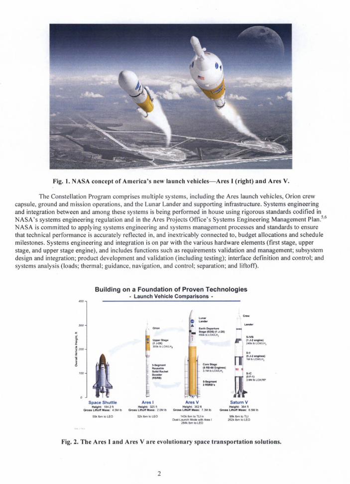
Fig. 1. NASA concept of America's new launch vehicles-Ares I (right) and Ares V.
The Constellation Program comprises mUltiple systems, including the Ares launch vehicles, Orion crewcapsule, ground and mission operations, and the Lunar Lander and supporting infrastructure. Systems engineeringand integration between and among these systems is being performed in house using rigorous standards codified inNASA's systems engineering regulation and in the Ares Projects Office's Systems Engineering Management Plan.5
,6
NASA is committed to applying systems engineering and systems management processes and standards to ensurethat technical performance is accurately reflected in, and inextricably connected to, budget allocations and schedulemilestones. Systems engineering and integration is on par with the various hardware elements (first stage, upperstage, and upper stage engine), and includes functions such as requirements validation and management; subsystemdesign and integration; product development and validation (including testing); interface definition and control; andsystems analysis (loads; thermal; guidance, navigation, and control; separation; and liftoff).
Building on a Foundation of Proven Technologies- Launch Vehicle Comparisons -
400
5-1115J·2I1ng1nes'1M lbLOXllH,
,,",VB(1J·2~lne)
240k lb lOXllH,
CoreS~
(5 R5-11 Er9nul3'MblO~
"".........2 RSRS'.
Orion
""-,ReusableSoHd RocketBoost.r(RSRB)
Upper Stage
• (1 J-VC)305lIlblOXJLH,
'00
300
Space ShuttleHeight: 1804.2 ft
Gro.. Liftoff Mu.: 4.5M Ib
Ares IHeight; 325 ft
Gloss Liftoff Mus: 2 OM Ib
Ares VHeight: 362 It
Gf"o.. liftoff M•••: 7.3M Ib
Saturn VHeight: 364l ft
Gro•• liftoff M...: 8.5M Ib
55k Ibm 10 lEO 52k Ibm 10 lEO ,43k Ibm to rUin0u81.l1U'1Ch Mode WIth Ares I
284k Ibm 10 lEO
99k Ibm 10 Ttl262k Ibm 10 LEO
Fig. 2. The Aloes I and Ares V are evolutionary space transportation solutions.
2
The Ares [ team consists of the range of engineering and business disciplines that come together formallyand informally in working groups, integrated product teams, and governing councils and boards. In this way,decision-making is handled at the lowest possible level in most cases. As a testament to this systems engineeringnetwork, which includes the Chief Engineers and Safety and Mission Assurance representatives assigned to theproject, in October 2007, the Ares team completed the second major milestone in the integrated vehicle's path tofielding - the System Definition Review - followed by an integrated vehicle technical interchange meeting, whichuncovered several dynamic and weight challenges now being addressed by focus teams studying various options forresolution. The previous milestone - the System Requirements Review - was completed in November 2006. Thisreview was focused on requirements validation and verification, and risk identification and mitigation, as well asbaselining the reference vehicle design from which to continue systems engineering work.
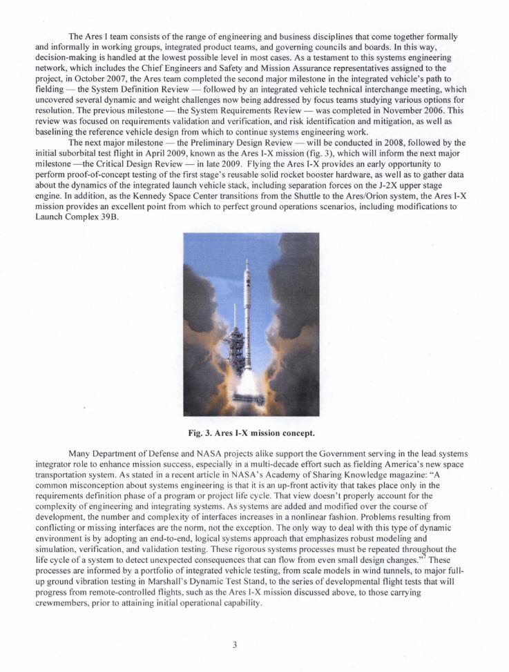
The next major milestone - the Preliminary Design Review - will be conducted in 2008, followed by theinitial suborbital test flight in April 2009, known as the Ares [-X mission (fig. 3), which will inform the next majormilestone -the Critical Design Review - in late 2009. Flying the Ares [-X provides an early opportunity toperform proof-of-concept testing of the first stage's reusable solid rocket booster hardware, as well as to gather dataabout the dynamics of the integrated launch vehicle stack, including separation forces on the J-2X upper stageengine. [n addition, as the Kennedy Space Center transitions from the Shuttle to the Ares/Orion system, the Ares [-Xmission provides an excellent point from which to perfect ground operations scenarios, including modifications toLaunch Complex 39B.
Fig. 3. Ares I-X mission concept.
Many Department of Defense and NASA projects alike support the Government serving in the lead systemsintegrator role to enhance mission success, especially in a multi-decade effort such as fielding America's new spacetransportation system. As stated in a recent article in NASA's Academy of Sharing Knowledge magazine: "Acommon misconception about systems engineering is that it is an up-front activity that takes place only in therequirements definition phase ofa program or project life cycle. That view doesn't properly account for thecomplexity of engineering and integrating systems. As systems are added and modified over the course ofdevelopment, the number and complexity of interfaces increases in a nonlinear fashion. Problems resulting fromconflicting or missing interfaces are the norm, not the exception. The only way to deal with this type of dynamicenvironment is by adopting an end-to-end, logical systems approach that emphasizes robust modeling andsimulation, verification, and validation testing. These rigorous systems processes must be repeated throughout thelife cycle of a system to detect unexpected consequences that can flow from even small design changes.,,7 Theseprocesses are informed by a portfolio of integrated vehicle testing, from scale models in wind tunnels, to major fullup ground vibration testing in Marshall's Dynamic Test Stand, to the series of developmental flight tests that willprogress from remote-controlled flights, such as the Ares [-X mission discussed above, to those carryingcrewmembers, prior to attaining initial operational capability.
3

Systems engineering and integration builds and bridges communication channels between projectmanagement and technical implementation teams, and within the various technical working groups where launchvehicle design, analysis, and testing are performed. It provides a framework for risk reduction and mission successbuilt on the foundation of principles and practices that position hardware and software in a collaborativeenvironment where government and contractor interests are united behind a common agenda.
II. Upper Stage Design
Whereas the ESAS suggested evolv"ing proven technologies, for example the 5-segment reusable solidrocket booster, where possible, it also recommended a clean-sheet design upper stage powered by an upper stageengine such as the Space Shuttle Main Engine (SSME). Subsequent trade studies found that developing the J-2Xengine for expendable use would be more cost effective than revamping the SSME for a throw-away application. Inshort, the upper stage is a new system, rather than a modification of an existing one. This approach allows engineersto fully incorporate state-of-the-art materials, processes, and hardware; adapt to vehicle configuration changes;standardize replacement parts; and build the upper stage to evolve with technological advances.
The Ares I upper stage is an aluminum-lithium alloy, self-supporting cylindrical structure that is 84-feetlong and 18-feet in diameter. This second stage will provide the guidance, navigation, and control, while the J-2Xupper stage engine will provide the thrust and propulsive impulse required for the second phase of the Ares I ascentflight after the first stage separates from the launch vehicle (fig. 4). The upper stage includes the main propulsionsystem, thrust vector control, avionics and software, reaction control system for roll and attitude control, and theseparation system required to perform the first stage separation. It also holds the liquid oxygen/liquid hydrogentanks for the J-2X engine operation. Most of the avionics will be housed in an instrument unit, which provides themechanical and electrical interfaces between the Ares I and the Orion.
Fig. 4. A concept drawing of the Ares I upper stage, which will transport the Orion crew capsule to orbit.
The upper stage design and development team includes hundreds of civil servant and contract employeeswho provide support services, such as assembling one of the largest friction-stir welding machines to test materialsand processes, as well as other members who create the designs, select the components, and conduct the tests to helpmake the second phase of the journey as safe, reliable, and cost-effective as possible. While an in-house team isdesigning the upper stage, it will be manufactured by the Boeing Company, which was selected in a competitiveprocurement process, using lean practices at NASA's Michoud Assembly Facility. This is a similar arrangement tothe Saturn and Space Shuttle vehicles. Using NASA's design, Boeing is responsible for producing a ground testarticle, three flight test units, and six production flight units to support the flight manifest through 2016. Theproduction contract was awarded in August 2007. The upper stage element's System Definition Review wasconducted in October 2007, and a variety of subsystem tests and a series of integrated main propulsion test articleand ground vibration testing are being planned to validate computer modeling and simulation. The upper stagePreliminary Design Review is slated for 2008.
4

References
I. NASA Constellation Architecture Requ irements Document, CxP 0000 1,2005.
2. U.S. National Space Policy, 2006, http://www.ostp.gov/
3. 2006 NASA Strategic Plan, NP-2006-02-423-HQ.
4. NASA Exploration Systems Architecture Study, Final Report, Technical Manual 2005-214062, November
2005, www.sti.nasa.gov
5. NASA Systems Engineering Processes and Requirements, NASA Procedure and Regulation 7123.1A,
March 26, 2007.
6. Ares Projects Office Systems Engineering Management Plan, CxP 72018, Oct 4, 2006.
7. Stephen Kapurch, NASA Academy of Sharing Knowledge, Spring 2007, p. 37.
5